Creating a Keyplan - Generic Annotation Family · PDF fileCreating a Keyplan - Generic...
18
Creating a Keyplan - Generic Annotation Family In this tutorial, you use a generic annotation family to create a keyplan symbol that can be used on multiple sheets in a project. You export a building plan to use as the basis for the keyplan geometry. You create a keyplan annotation with 2 family types. Depending on the type selected, the corresponding wing is shaded and labeled in the annotation, as shown: 8 173
Transcript of Creating a Keyplan - Generic Annotation Family · PDF fileCreating a Keyplan - Generic...

Creating a Keyplan -
Generic Annotation
Family
In this tutorial, you use a generic annotation family to create a keyplan symbol that can be used on multiple sheets in aproject.
You export a building plan to use as the basis for the keyplan geometry.
You create a keyplan annotation with 2 family types. Depending on the type selected, the corresponding wing is shadedand labeled in the annotation, as shown:
8
173

Skills used in this tutorial:
n Exporting a building plan as a DWG file
n Importing a DWG file to use as the basis for a keyplan annotation
n Creating annotation geometry
n Defining object styles
n Adding filled regions
n Adding parameters to control keyplan shading and labelling
n Adding the keyplan to a project sheet
Creating the Keyplan Geometry
In this exercise, you create the geometry for the keyplan by importing a DWG file and tracing the outline
of the building plan. You add object styles to the family, and create filled regions to shade the 2 sections of
the keyplan.
Export the plan of the building to a DWG file
1 Click File menu ä Open.
2 In the left pane of the Open dialog, click Training Files, and open Metric\m_Dependent_Views.rvt.
3 Zoom to fit (ZF) the Level 2 floor plan in the window.
174 | Chapter 8 Creating a Keyplan - Generic Annotation Family
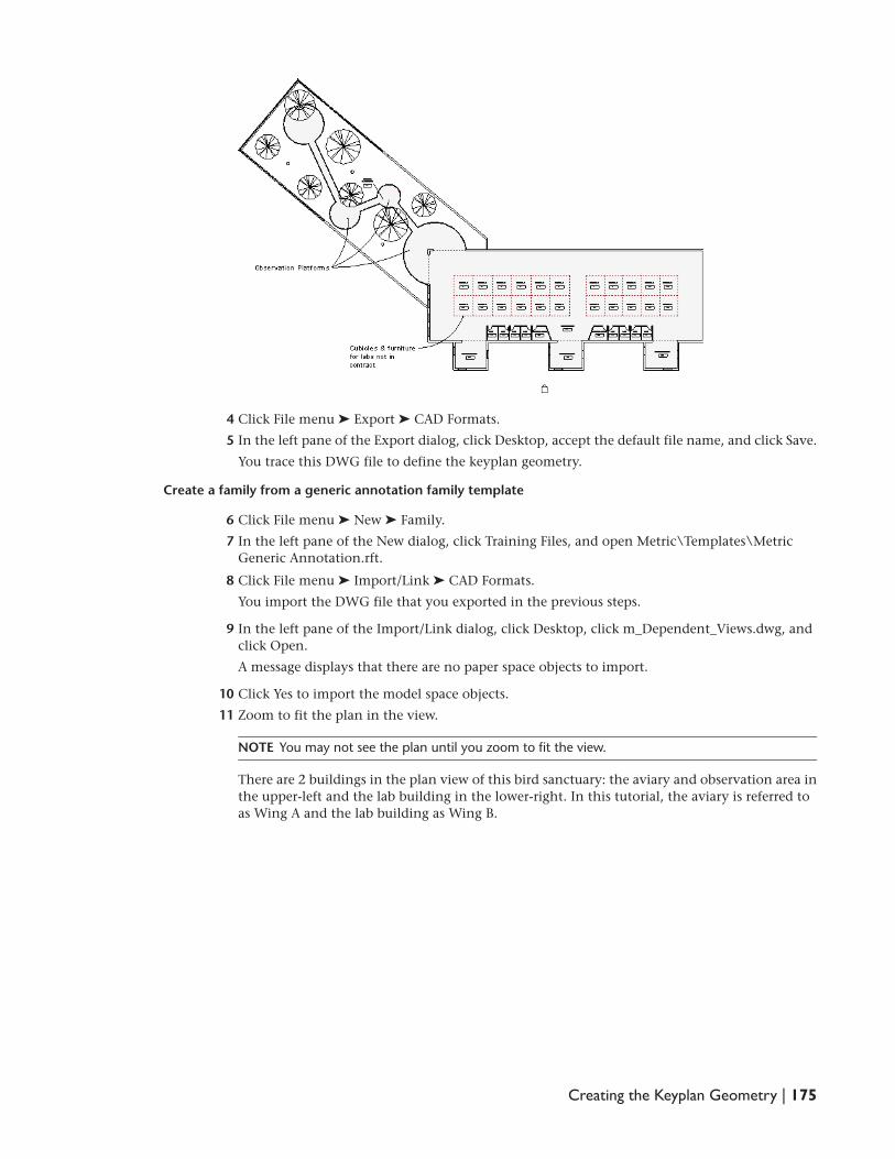
4 Click File menu ä Export ä CAD Formats.
5 In the left pane of the Export dialog, click Desktop, accept the default file name, and click Save.
You trace this DWG file to define the keyplan geometry.
Create a family from a generic annotation family template
6 Click File menu ä New ä Family.
7 In the left pane of the New dialog, click Training Files, and open Metric\Templates\Metric
Generic Annotation.rft.
8 Click File menu ä Import/Link ä CAD Formats.
You import the DWG file that you exported in the previous steps.
9 In the left pane of the Import/Link dialog, click Desktop, click m_Dependent_Views.dwg, and
click Open.
A message displays that there are no paper space objects to import.
10 Click Yes to import the model space objects.
11 Zoom to fit the plan in the view.
NOTE You may not see the plan until you zoom to fit the view.
There are 2 buildings in the plan view of this bird sanctuary: the aviary and observation area in
the upper-left and the lab building in the lower-right. In this tutorial, the aviary is referred to
as Wing A and the lab building as Wing B.
Creating the Keyplan Geometry | 175

12 Click File menu ä Save As.
13 In the left pane of the Save As dialog use the scroll button, click Training Files, and save the file
as \Metric\Families\Annotations\Keyplan.
The family file is saved automatically with the .rfa extension.
Resize the plan for a keyplan
You use the Resize tool to make the plan the required size (printed size) for the keyplan. The keyplan will
be used on sheets in Revit Architecture projects, so it will have no scaling applied.
14 In the drawing area, select the imported geometry.
15 On the Edit toolbar, click (Resize).
16 Zoom in to the far right area of Wing A (near where the wings connect).
176 | Chapter 8 Creating a Keyplan - Generic Annotation Family
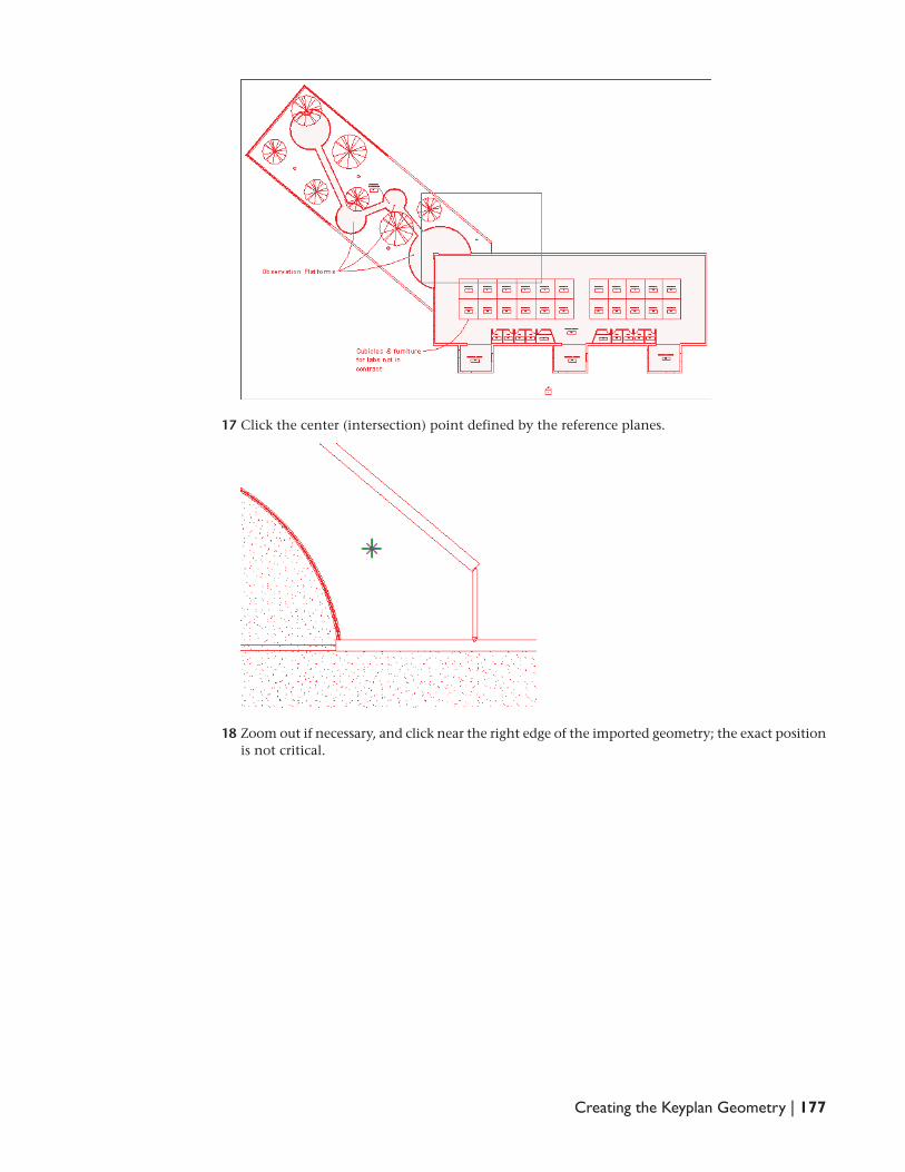
17 Click the center (intersection) point defined by the reference planes.
18 Zoom out if necessary, and click near the right edge of the imported geometry; the exact position
is not critical.
Creating the Keyplan Geometry | 177

19 Enter 50 mm, and press ENTER.
Because you are resizing from the center point, this value is 1/2 the size of the desired printing
size of 100 mm. The imported geometry will be approximately 100 mm from the left extents of
the geometry to the right extents of the geometry.
20 Zoom to fit the geometry into the view.
178 | Chapter 8 Creating a Keyplan - Generic Annotation Family

Trace the outline of the plan
21 Zoom in to the intersection of the reference planes.
22 On the View toolbar, click (toggles Thin Lines).
23 Zoom in to the upper-left corner of the model, as shown:
24 On the Design Bar, click Lines.
25 On the Options Bar, click (Draw), and select Chain.
Creating the Keyplan Geometry | 179

26 Select the upper endpoint.
27 Select the lower-left endpoint.
28 Continue to draw lines counterclockwise to trace the outline of the plan. (Zoom out as needed.)
29 On the Design Bar, click Modify.
After you trace the outline of the plan, you can delete the imported DWG geometry.
30 Select the imported DWG, and press DELETE.
180 | Chapter 8 Creating a Keyplan - Generic Annotation Family
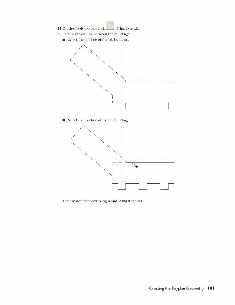
31 On the Tools toolbar, click (Trim/Extend).
32 Extend the outline between the buildings:
n Select the left line of the lab building.
n Select the top line of the lab building.
The division between Wing A and Wing B is clear.
Creating the Keyplan Geometry | 181
Add object styles to the family for lineweights/linetypes
33 Click Settings menu ä Objects Styles.
34 Define a dashed line for the match line:
n In the Object Styles dialog, under Modify Subcategories, click New.
n In the New Subcategory dialog, for Name, enter Dashed Line, and click OK.
n For Dashed Line, under Line Weight Projection, select 4, and for Line Pattern, select Dash.
35 Define a thick line for the keyplan outline:
n In the Object Styles dialog, under Modify Subcategories, click New.
n In the New Subcategory dialog, for Name, enter Thick Line, and click OK.
n For Thick Line, under Line Weight Projection, select 5.
36 Click OK.
Draw lines representing the match line of the plan
37 On the Design Bar, click Lines.
38 In the Type Selector, select Dashed Line.
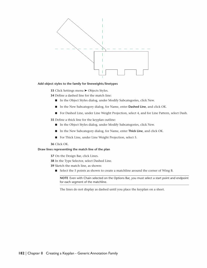
39 Sketch the match line, as shown:
n Select the 5 points as shown to create a matchline around the corner of Wing B.
NOTE Even with Chain selected on the Options Bar, you must select a start point and endpoint
for each segment of the matchline.
The lines do not display as dashed until you place the keyplan on a sheet.
182 | Chapter 8 Creating a Keyplan - Generic Annotation Family
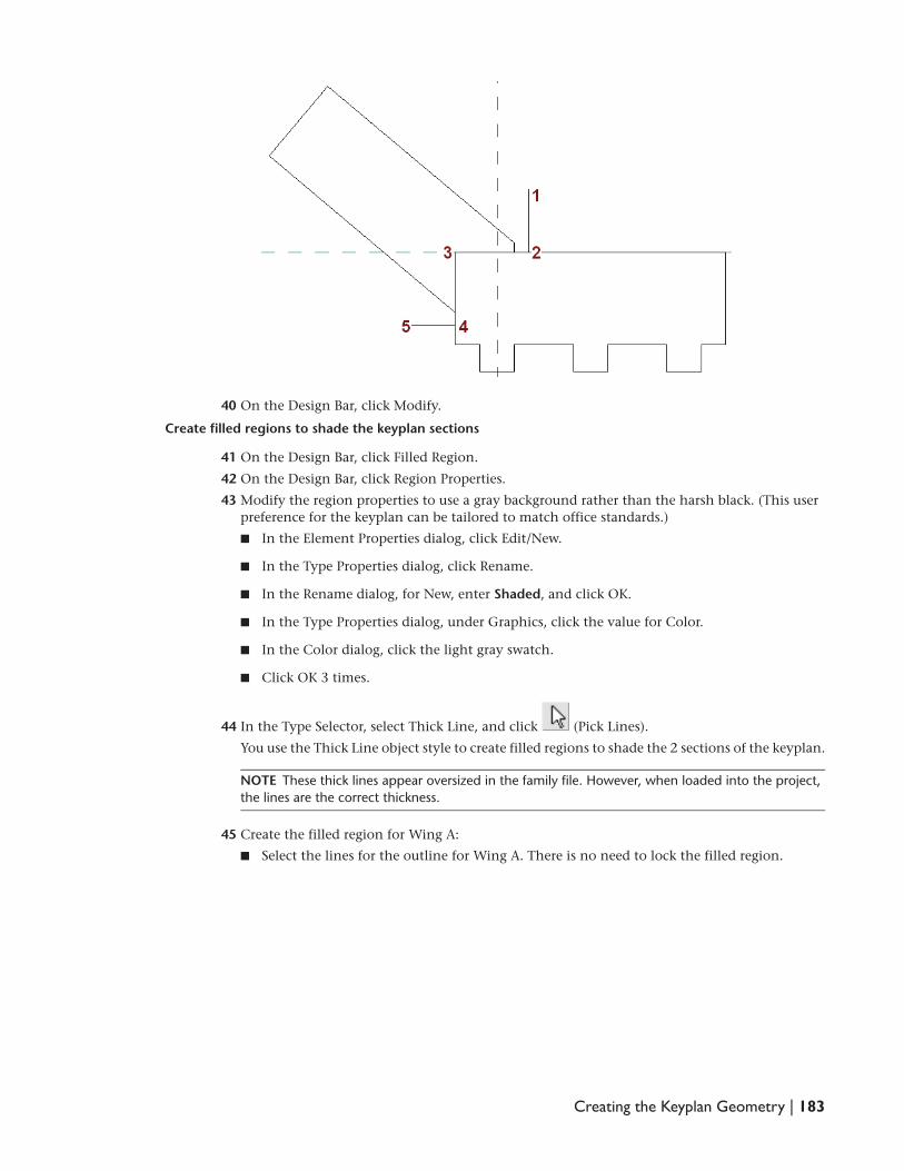
40 On the Design Bar, click Modify.
Create filled regions to shade the keyplan sections
41 On the Design Bar, click Filled Region.
42 On the Design Bar, click Region Properties.
43 Modify the region properties to use a gray background rather than the harsh black. (This user
preference for the keyplan can be tailored to match office standards.)
n In the Element Properties dialog, click Edit/New.
n In the Type Properties dialog, click Rename.
n In the Rename dialog, for New, enter Shaded, and click OK.
n In the Type Properties dialog, under Graphics, click the value for Color.
n In the Color dialog, click the light gray swatch.
n Click OK 3 times.
44 In the Type Selector, select Thick Line, and click (Pick Lines).
You use the Thick Line object style to create filled regions to shade the 2 sections of the keyplan.
NOTE These thick lines appear oversized in the family file. However, when loaded into the project,
the lines are the correct thickness.
45 Create the filled region for Wing A:
n Select the lines for the outline for Wing A. There is no need to lock the filled region.
Creating the Keyplan Geometry | 183

n On the Tools toolbar, click (Trim/Extend), and trim the lines to clean up the outline,
as shown:
n On the Design Bar, click Finish Sketch. Click as needed to manage display of the lines.
184 | Chapter 8 Creating a Keyplan - Generic Annotation Family
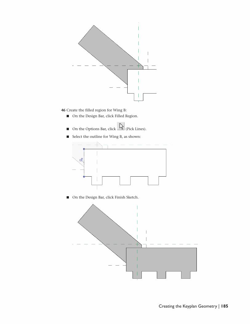
46 Create the filled region for Wing B:
n On the Design Bar, click Filled Region.
n On the Options Bar, click (Pick Lines).
n Select the outline for Wing B, as shown:
n On the Design Bar, click Finish Sketch.
Creating the Keyplan Geometry | 185

47 Click File menu ä Save.
48 Proceed to the next exercise, Add Parameters to Control Keyplan Visibility on page 186.
Add Parameters to Control Keyplan Visibility
In this exercise, you create 2 family types: 1 type shows wing A shaded and labeled; the other type shows
wing B shaded and labeled. You then create a sheet in a Revit Architecture project, and add the 2 keyplan
types to the sheet.
Define 2 family types
1 On the Design Bar, click Family Types.
2 In the Family Types dialog, under Family Types, click New.
3 In the Name dialog, enter Wing A, and click OK.
4 Using the same method, create a family type named Wing B.
Create Yes/No parameters for Wing A and Wing B
5 In the Family Types dialog, under Parameters, click Add.
You create a Yes/No parameter for each wing. You then associate these parameters with the
visibility of the filled regions and the text labels.
6 In the Parameter Properties dialog, under Parameter Data, for Name, enter Wing A, for Type of
Parameter, select Yes/No, and click OK.
7 Using the same method, create a yes/no parameter for Wing B.
Specify the visibility for each type
8 In the Family Types dialog, for Name, verify that family type Wing B is selected.
9 Under Other, clear the Value for Wing A.
10 Under Name, select Wing A, and clear the Value for Wing B.
11 Click OK.
Assign the yes/no parameter to the visibility of the filled regions
12 In the drawing area, select Wing A, and click (Element Properties).
13 In the Element Properties dialog, for Visible, click .
14 In the Associate Family Parameter dialog, select Wing A, and click OK twice.
15 Using the same method, assign the Wing B parameter to the visibility for Wing B.
186 | Chapter 8 Creating a Keyplan - Generic Annotation Family

16 On the Design Bar, click Modify.
Create a text label for the keyplan
17 On the Design Bar, click Text, and click (Element Properties).
18 In the Element Properties dialog, click Edit/New.
You create a text type. The size of the text label for a keyplan is typically determined by office
standard text sizes/fonts.
19 In the Type Properties dialog, click Duplicate.
20 For Name, enter 5 mm, and click OK.
21 In the Type Properties dialog, under Text, for Text Size, enter 5 mm.
22 Click OK twice.
23 Click in the lower left area of the drawing area, and enter Key Plan -.
24 On the Design Bar, click Modify.
25 In the drawing area, select the new text box.
26 On the Edit toolbar, click (Move Copies).
Add Parameters to Control Keyplan Visibility | 187

27 Click the bottom left corner of the text box for the start point, and click to the right of the
existing text box to place the copy.
This second text box will be connected to the visibility parameters and will contain text specific
to each family type (that is, Wing A or Wing B). You create 2 copies of the second text box, one
copy for each of the 2 family types.
28 Edit the second text box to read Wing A.
29 On the Design Bar, click Modify.
30 Select the Wing A text, and click (Element Properties).
31 In the Element Properties dialog, for Visible, click .
32 In the Associate Family Parameter dialog, select Wing A.
33 Click OK twice.
34 Create a Wing B text box:
n Create a copy of the Wing A text box.
n Select the copy, and change the text to Wing B.
n With the Wing B text box still selected, click (Element Properties).
n In the Element Properties dialog, for Visible, click .
Notice that = displays on the button because the visibility is already associated with Wing
A.
n In the Associate Family Parameter dialog, select Wing B.
n Click OK twice.
n Drag the Wing B text box so that it is positioned directly over the Wing A text box.
35 On the Design Bar, click Modify.
36 Select the notes in the template file, and press DELETE.
188 | Chapter 8 Creating a Keyplan - Generic Annotation Family

37 Click File menu ä Save.
38 On the Design Bar, click Load into Projects.
39 If necessary, in the Load into Projects dialog, select m_Dependent_Views.rvt, and click OK.
The m_Dependent_Views project opens and the keyplan family is loaded into the project.
Create a sheet for the keyplan
40 In the Project Browser, right-click Sheets (all), and click New Sheet.
41 In the Select a Titleblock dialog, select the default titleblock, and click OK.
Add the generic annotation to the sheet
42 On the Drafting tab of the Design Bar, click Symbol.
43 Click in the upper-right corner of the sheet.
44 Click to place a second instance of the annotation below the first so the 2 types can be tested
and compared.
45 On the Design Bar, click Modify.
46 Select the second instance of the annotation, and in the Type Selector, select Keyplan : Wing
B.
Add Parameters to Control Keyplan Visibility | 189
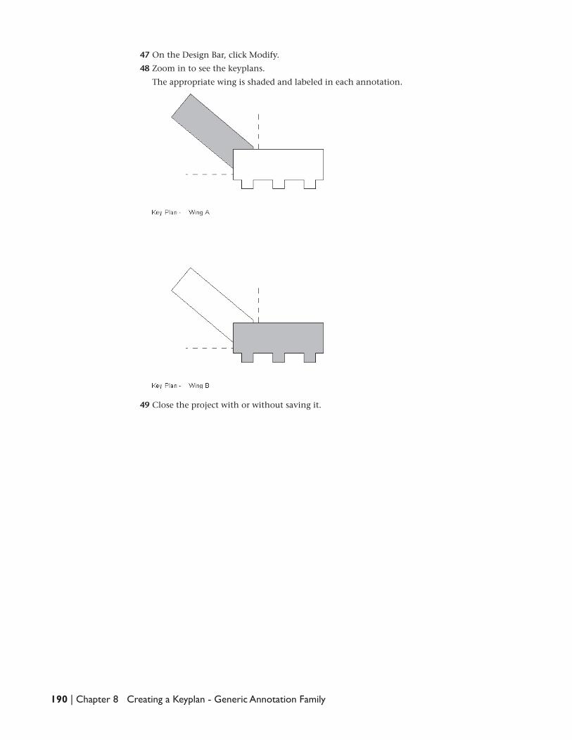
47 On the Design Bar, click Modify.
48 Zoom in to see the keyplans.
The appropriate wing is shaded and labeled in each annotation.
49 Close the project with or without saving it.
190 | Chapter 8 Creating a Keyplan - Generic Annotation Family