
CRAWLER EXCAVATOR CX210B-CX230B-CX240B SERVICE MANUAL …€¦ · · 2017-06-01CRAWLER EXCAVATOR...
25
CRAWLER EXCAVATOR CX210B-CX230B-CX240B SERVICE MANUAL TABLE OF CONTENTS DIVISION/SECTION SECTION N° REFERENCE N° 1 GENERAL INFORMATION Safety, general information and standard torque data .....................................1001 7-27691EN General specifications and special torque setting............................................1002 SC210B1002-0EN 2 ENGINE Removal and installation of the engine ............................................................2000 SM210B2000-0EN Radiator and oil-cooler .....................................................................................2001 SM210B2001-0EN Engine specifications ............................................................................................. * Disassembly and assembly of the engine .............................................................. * 3 FUEL SYSTEM Fuel tank ..........................................................................................................3001 SM160B3001-0EN Fuel engine system ................................................................................................ * 4 ELECTRICAL SYSTEM Electrical system, electrical and electronic troubleshooting .............................4001 SC210B4001-1EN Electrical equipment and electrical circuit diagrams ........................................4020 SC210B4020-0EN 5 UNDERCARRIAGE Removal and installation of tracks ...................................................................5001 SM160B5001-0EN Rollers .............................................................................................................5003 SM160B5003-0EN Sprocket ...........................................................................................................5004 SM160B5004-0EN Idler wheel and tension shock absorber ..........................................................5005 SM160B5005-0EN 6 DRIVE TRAIN Drive motor and final drive transmission removal and installation ...................6001 SM160B6001-0EN Drive motor and final drive transmission disassembly and assembly ..............6002 SM160B6002-0EN Swing reduction gear, removal and installation ................................................6003 SM160B6003-0EN Swing reduction gear, disassembly and assembly (CX210B - CX230B) .........6004 SM210B6004-0EN Swing reduction gear, disassembly and assembly (CX240B) ..........................6004 SM240B6004-0EN 7 UNDERCARRIAGE HYDRAULICS 8 UPPERSTRUCTURE HYDRAULICS Depressurising and decontaminating the hydraulic system, use of the vacuum pump and bleeding the components ..............................................8000 SM160B8000-0EN Specifications, troubleshooting, checks and hydraulic pressure settings.........8001 SC210B8001-2EN Hydraulic reservoir removal and installation ...................................................8002 SM160B8002-0EN Main and hydraulic pilot pumps, removal and installation ..............................8003 SM210B8003-0EN Main hydraulic control valve, removal and installation ....................................8004 SM210B8004-0EN Attachment cylinders, removal and installation ...............................................8005 SM160B8005-0EN Hydraulic swivel, removal and installation .......................................................8006 SM160B8006-0EN Pilot blocs, removal and installation .................................................................8007 SM160B8007-0EN Swing motor, removal and installation..............................................................8008 SM160B8008-0EN Main hydraulic pump, disassembly and assembly ...........................................8010 SM210B8010-0EN Main hydraulic pump, disassembly and assembly (CX210B NLC) ..................8010 SM210BNLC8010-0EN Hand control levers, disassembly and assembly .............................................8013 SM160B8013-0EN Foot control levers, disassembly and assembly ...............................................8014 SM160B8014-0EN Caution valve, disassembly and assembly.......................................................8016 SM160B8016-0EN Swing motor, disassembly and assembly (CX210B - CX230B) .......................8019 SM160B8019-0EN Swing motor, disassembly and assembly (CX240B)........................................8019 SM240B8019-0EN Hydraulic functions...........................................................................................8020 SC210B8020-1EN Hydraulic component functions ........................................................................8030 SC210B8030-0EN
Transcript of CRAWLER EXCAVATOR CX210B-CX230B-CX240B SERVICE MANUAL …€¦ · · 2017-06-01CRAWLER EXCAVATOR...
CRAWLER EXCAVATOR CX210B-CX230B-CX240BSERVICE MANUAL
TABLE OF CONTENTSDIVISION/SECTION SECTION N° REFERENCE N°
1 GENERAL INFORMATIONSafety, general information and standard torque data .....................................1001 7-27691ENGeneral specifications and special torque setting............................................1002 SC210B1002-0EN
2 ENGINERemoval and installation of the engine ............................................................2000 SM210B2000-0ENRadiator and oil-cooler.....................................................................................2001 SM210B2001-0ENEngine specifications ............................................................................................. *Disassembly and assembly of the engine.............................................................. *
3 FUEL SYSTEMFuel tank ..........................................................................................................3001 SM160B3001-0ENFuel engine system................................................................................................ *
4 ELECTRICAL SYSTEMElectrical system, electrical and electronic troubleshooting.............................4001 SC210B4001-1ENElectrical equipment and electrical circuit diagrams ........................................4020 SC210B4020-0EN
5 UNDERCARRIAGERemoval and installation of tracks ...................................................................5001 SM160B5001-0ENRollers .............................................................................................................5003 SM160B5003-0ENSprocket ...........................................................................................................5004 SM160B5004-0ENIdler wheel and tension shock absorber ..........................................................5005 SM160B5005-0EN
6 DRIVE TRAINDrive motor and final drive transmission removal and installation ...................6001 SM160B6001-0ENDrive motor and final drive transmission disassembly and assembly ..............6002 SM160B6002-0ENSwing reduction gear, removal and installation................................................6003 SM160B6003-0ENSwing reduction gear, disassembly and assembly (CX210B - CX230B) .........6004 SM210B6004-0ENSwing reduction gear, disassembly and assembly (CX240B)..........................6004 SM240B6004-0EN
7 UNDERCARRIAGE HYDRAULICS
8 UPPERSTRUCTURE HYDRAULICSDepressurising and decontaminating the hydraulic system, use of the
vacuum pump and bleeding the components ..............................................8000 SM160B8000-0ENSpecifications, troubleshooting, checks and hydraulic pressure settings.........8001 SC210B8001-2ENHydraulic reservoir removal and installation ...................................................8002 SM160B8002-0ENMain and hydraulic pilot pumps, removal and installation ..............................8003 SM210B8003-0ENMain hydraulic control valve, removal and installation ....................................8004 SM210B8004-0ENAttachment cylinders, removal and installation ...............................................8005 SM160B8005-0ENHydraulic swivel, removal and installation .......................................................8006 SM160B8006-0ENPilot blocs, removal and installation .................................................................8007 SM160B8007-0ENSwing motor, removal and installation..............................................................8008 SM160B8008-0ENMain hydraulic pump, disassembly and assembly ...........................................8010 SM210B8010-0ENMain hydraulic pump, disassembly and assembly (CX210B NLC) ..................8010 SM210BNLC8010-0ENHand control levers, disassembly and assembly .............................................8013 SM160B8013-0ENFoot control levers, disassembly and assembly ...............................................8014 SM160B8014-0ENCaution valve, disassembly and assembly.......................................................8016 SM160B8016-0ENSwing motor, disassembly and assembly (CX210B - CX230B) .......................8019 SM160B8019-0ENSwing motor, disassembly and assembly (CX240B)........................................8019 SM240B8019-0ENHydraulic functions...........................................................................................8020 SC210B8020-1ENHydraulic component functions........................................................................8030 SC210B8030-0EN

Lep SM210BTOC-0EN Issued 05-07
DIVISION/SECTION SECTION N° REFERENCE N°
9 UPPERSTRUCTUREQuick coupler..................................................................................................... 9000 SM160B9000-0ENUpperstructure, turntable and counterweight..................................................... 9002 SM160B9002-0ENBoom, dipper and bucket ................................................................................... 9003 SM160B9003-0ENSeat, removal and installation............................................................................ 9004 SM160B9004-0ENCab and cab equipment..................................................................................... 9005 SM160B9005-0ENAir conditioner functions and troubleshooting.................................................... 9006 SC210B9006-0ENLarge size hydraulic schematics CX210B-CX230B .........................................Pocket 87598349ALarge size hydraulic schematics CX240B........................................................Pocket 87600987ALarge size electrical schematics ......................................................................Pocket 87598355A
* Consult the Engine Service Manual
NOTE: CNH Company reserves the r ight to make changes in the specifica tion and design of the machine without prior notice and without incurring any obliga-tion to modify units previously sold.
The description of the models shown in this manual has been made in accord-ance with the technical specifications known as of the date of design of this document.

CNH Lep 7-27691EN
1001
SAFETY, GENERAL INFORMATIONAND TORQUE SPECIFICATIONS
Section
1001
1001-2
Lep 7-27691EN Issued 02-06
TABLE OF CONTENTSGENERAL INFORMATION .......................................................................................................................................3
SAFETY.....................................................................................................................................................................4
STANDARD TORQUE DATA FOR CAP SCREWS AND NUTS...............................................................................6
WARNING : This symbol is used in this manual to indicate important safety messages. Whenever you seethis symbol, carefully read the message that follows, as there is a risk of serious injury.!

1001-3
Lep 7-27691EN Issued 02-06
GENERAL INFORMATIONCleanningClean all metal par ts except bear ings, in a suitab lecleaning so lvent or b y ste am clea ning. Do not usecaustic sod a for st eam clean ing. After clea ning, dryand put o il on al l pa rts. Clea n o il p assages withcompressed air. Clean bearings in a suitable cleaningsolvent, dry th e be arings completely an d pu t oil onthe bearings.
InspectionCheck a ll parts whe n th e pa rts ar e disassemb led.Replace a ll pa rts t hat h ave wear o r d amage. Smallscoring or g rooves can be r emoved wit h a ho ne o rcrocus clot h. Com plete a visual in spection forindications of w ear, p itting an d the r eplacement o fparts necessary to prevent early failures.
BearingsCheck b earings f or easy actio n. If be arings ha ve aloose f it or ro ugh act ion r eplace t he bea ring. Washbearings with a suitable cleaning solvent and permitto air dr y. DO NO T DR Y BEARIN GS WITHCOMPRESSED AIR.
Needle bearingsBefore you pr ess nee dle bearings in a bore alwaysremove any metal protrusions in the bore or edge ofthe bore. Before you press bearings into position putpetroleum jelly on the inside and outside diameter ofthe bearings.
GearsCheck all gears for wear and damage. Replace gearsthat have wear or damage.
Oil seals, O-rings and gasketsAlways install new oil seals, O-rings and gaskets. Putpetroleum jelly on seals and O-rings.
ShaftsCheck all shaf ts t hat have w ear or dam age. Ch eckthe bearing a nd oil seal surfaces of t he sha fts f ordamage.
Service partsAlways install gen uine Case ser vice par ts. Whenordering refer to the Parts Catalog for the correct partnumber of t he g enuine Case r eplacement ite ms.Failures due to the use of other than genuine Casereplacement parts are not covered by warranty.
LubricationOnly use t he o ils and lubr icants spe cified in t heOperator’s or Service Ma nuals. Failures du e to th euse o f no n-specified o ils an d lub ricants are notcovered by warranty.

1001-4
Lep 7-27691EN Issued 02-06
SAFETY
This symbol means ATTENTION! BECOME ALERT! YOURSAFETY IS INVOLVED. The message that follows thesymbol contains important information about safety. Carefullyread the message. Make sure you fully understand thecauses of possible injury or death.
!
To prevent injury always follow the Warning, Cautionand Danger notes in t his section and throughout themanual.
Put the warning tag shown below on the key for thekeyswitch w hen ser vicing or repairing the machine .One warning t ag is supplied with ea ch m achine.Additional tags Part Number 331-4614 are availablefrom your service parts supplier
.
WARNING: Read the operator’s manual tofamiliarize yourself with the correct controlfunctions.
!
WARNING: Operate the machine andequipment controls from the seat positiononly. Any other method could result inserious injury.
!
WARNING: This is a one man machine, noriders allowed. !
WARNING: Before starting engine, studyOperator’s Manual safety messages. Readall safety signs on machine. Clear the area ofother persons. Learn and practice safe useof controls before operating.It is your responsibility to understand andfol low manufacturers instruct ions onmachine operation, service and to observepertinent laws and regulations. Operator’sand Service Manuals may be obtained fromyour Case dealer.
!
WARNING: If you wear clothing that is tooloose or do not use the correct safetyequipment for your job, you can be injured.Always wear clothing that will not catch onobjects. Extra safety equipment that can berequired includes hard hat, safety shoes, earprotection, eye or face protection, heavygloves and reflector clothing.
!
WARNING: When working in the area of thefan belt with the engine running, avoid looseclothing if possible, and use extreme caution.
!
WARNING: When doing checks and testson the equipment hydraulics, follow theprocedures as they are written. DO NOTchange the procedure.
!
WARNING: When putting the hydrauliccylinders on this machine through thenecessary cycles to check operation or toremove air from a circuit, make sure allpeople are out of the way.
!
1001-5
Lep 7-27691EN Issued 02-06
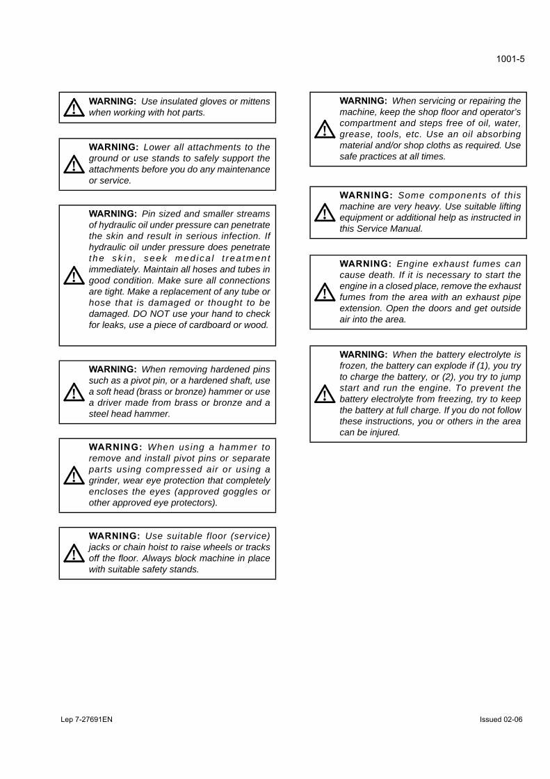
WARNING: Use insulated gloves or mittenswhen working with hot parts.!
WARNING: Lower all attachments to theground or use stands to safely support theattachments before you do any maintenanceor service.
!
WARNING: Pin sized and smaller streamsof hydraulic oil under pressure can penetratethe skin and result in serious infection. Ifhydraulic oil under pressure does penetratethe sk in , seek med ica l t rea tmen timmediately. Maintain all hoses and tubes ingood condition. Make sure all connectionsare tight. Make a replacement of any tube orhose that is damaged or thought to bedamaged. DO NOT use your hand to checkfor leaks, use a piece of cardboard or wood.
!
WARNING: When removing hardened pinssuch as a pivot pin, or a hardened shaft, usea soft head (brass or bronze) hammer or usea driver made from brass or bronze and asteel head hammer.
!
WARNING: When using a hammer toremove and install pivot pins or separateparts using compressed air or using agrinder, wear eye protection that completelyencloses the eyes (approved goggles orother approved eye protectors).
!
WARNING: Use suitable floor (service)jacks or chain hoist to raise wheels or tracksoff the floor. Always block machine in placewith suitable safety stands.
!
WARNING: When servicing or repairing themachine, keep the shop floor and operator’scompartment and steps free of oil, water,grease, tools, etc. Use an oil absorbingmaterial and/or shop cloths as required. Usesafe practices at all times.
!
WARNING: Some components of thismachine are very heavy. Use suitable liftingequipment or additional help as instructed inthis Service Manual.
!
WARNING: Engine exhaust fumes cancause death. If it is necessary to start theengine in a closed place, remove the exhaustfumes from the area with an exhaust pipeextension. Open the doors and get outsideair into the area.
!
WARNING: When the battery electrolyte isfrozen, the battery can explode if (1), you tryto charge the battery, or (2), you try to jumpstart and run the engine. To prevent thebattery electrolyte from freezing, try to keepthe battery at full charge. If you do not followthese instructions, you or others in the areacan be injured.
!

1001-6
Lep 7-27691EN Issued 02-06
STANDARD TORQUE DATA FOR CAP SCREWS AND NUTSTightening of cap screws, nutsTighten alternately so that tightening torque can be applied evenly. The numbers in the figure below indicate theorder of tightening.
JS00481A
Cap screws which have had Loctite used (white residue remains after removal) should be cleaned with loght oil orsuitable cleaning solvent and dr ied. Apply 2- 3 drops of Loctite to the thread portion o f the cap screw and thentighten.
Torque tableTighten cap screws and nuts according to the table below if there are no other special instructions.
Cap Screw Name Size (Size) M6 M8 M10 M12 M14 M16 M18 M20
Cap Screw
Spanner[mm] 10 13 17 19 22 24 27 30
[in.] 0.39 0.51 0.67 0.75 0.87 0.95 1.06 1.18
Tighteningtorque
[Nm] 6.9 19.6 39.2 58.8 98.1 156.9 196.1 294.2
[lb-ft] 5.1 14.5 28.9 43.4 72.3 115.7 144.6 217
Socket Head Cap Screw
Spanner[mm] 5 6 8 10 12 14 14 17
[in.] 0.20 0.24 0.32 0.39 0.47 0.55 0.55 0.67
Tightening torque
[Nm] 8.8 21.6 42.1 78.5 117.7 176.5 245.2 343.2
[lb-ft] 6.5 15.9 31.1 57.9 86.9 130.2 181 253.2

CNH Lep SC210B1002-0EN
1002
SPECIFICATIONS
AND SPECIAL TORQUE SETTINGS
Section
1002

Lep SC160B1002-0EN Issued 02-07
1002-2
TABLE OF CONTENTS
TYPE, SERIAL NUMBERAND YEAR OF MANUFACTURE OF THE MACHINE..................................................................................................... 3
Machine ....................................................................................................................................................................... 3
Engine.......................................................................................................................................................................... 3
Serial numbers of the components .............................................................................................................................. 3
FLUIDS AND LUBRICANTS ............................................................................................................................................ 4
Hydraulic fluid .............................................................................................................................................................. 4
Transmission component oil ........................................................................................................................................ 4
Grease ......................................................................................................................................................................... 4
Engine Oil .................................................................................................................................................................... 5
Engine fuel, maintenance of fuel filters and fuel storage ............................................................................................. 6
Anti-freeze/Anti-corrosion............................................................................................................................................. 8
Environment ................................................................................................................................................................. 8
Plastic and resin parts.................................................................................................................................................. 8
SPECIFICATIONS ........................................................................................................................................................... 9
Main data ..................................................................................................................................................................... 9
Performance ................................................................................................................................................................ 9
Complete machine dimensions.................................................................................................................................. 10
Main body dimensions ............................................................................................................................................... 12
Engine........................................................................................................................................................................ 13
Cooling system .......................................................................................................................................................... 13
Capacity of coolant and lubricants ............................................................................................................................. 13
Hydraulic oil filter........................................................................................................................................................ 14
Fuel filter .................................................................................................................................................................... 14
Operating devices ...................................................................................................................................................... 14
Hydraulic system........................................................................................................................................................ 15
Swing unit .................................................................................................................................................................. 18
Travel lower body....................................................................................................................................................... 19
Work Unit ................................................................................................................................................................... 20
Digging force (ISO 6015) ........................................................................................................................................... 29
COMPONENT WEIGHT................................................................................................................................................. 30
Major component weight ............................................................................................................................................ 30
Other component weight ............................................................................................................................................ 32
SPECIAL TORQUE SETTINGS..................................................................................................................................... 34
MACHINE OVERALL DIMENSIONS ............................................................................................................................. 38
WARNING: This symbol is used in this manual to indicate important safety messages. Whenever you see thissymbol, carefully read the message which follows. Your safety depends on it.!
Lep SC210B1002-0EN Issued 02-07
1002-3
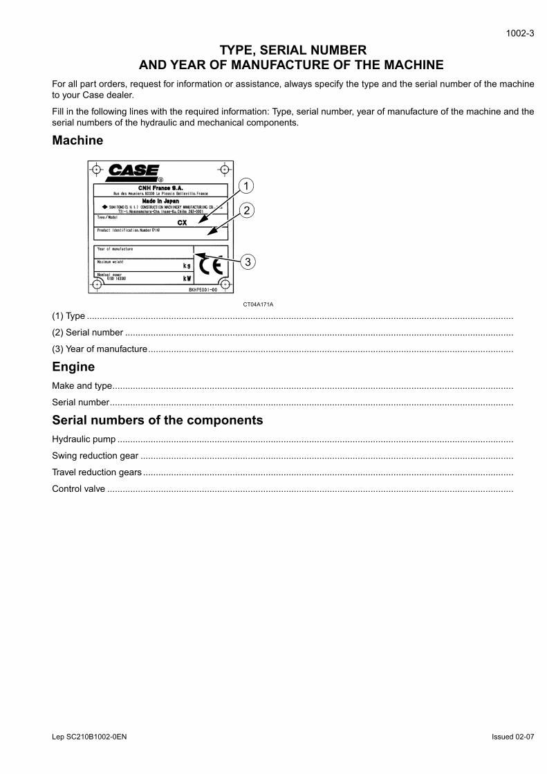
TYPE, SERIAL NUMBERAND YEAR OF MANUFACTURE OF THE MACHINE
For all part orders, request for information or assistance, always specify the type and the serial number of the machineto your Case dealer.
Fill in the following lines with the required information: Type, serial number, year of manufacture of the machine and theserial numbers of the hydraulic and mechanical components.
Machine
CT04A171A
(1) Type .......................................................................................................................................................................
(2) Serial number ........................................................................................................................................................
(3) Year of manufacture...............................................................................................................................................
EngineMake and type.............................................................................................................................................................
Serial number..............................................................................................................................................................
Serial numbers of the componentsHydraulic pump ...........................................................................................................................................................
Swing reduction gear ..................................................................................................................................................
Travel reduction gears .................................................................................................................................................
Control valve ...............................................................................................................................................................
1
3
2
Lep SC210B1002-0EN Issued 02-07
1002-4
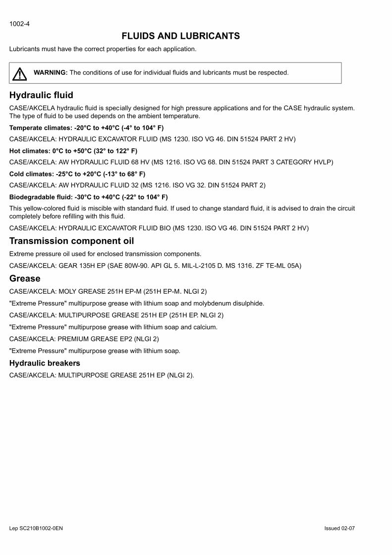
FLUIDS AND LUBRICANTS Lubricants must have the correct properties for each application.
Hydraulic fluidCASE/AKCELA hydraulic fluid is specially designed for high pressure applications and for the CASE hydraulic system.The type of fluid to be used depends on the ambient temperature.
Temperate climates: -20°C to +40°C (-4° to 104° F)CASE/AKCELA: HYDRAULIC EXCAVATOR FLUID (MS 1230. ISO VG 46. DIN 51524 PART 2 HV)
Hot climates: 0°C to +50°C (32° to 122° F)CASE/AKCELA: AW HYDRAULIC FLUID 68 HV (MS 1216. ISO VG 68. DIN 51524 PART 3 CATEGORY HVLP)
Cold climates: -25°C to +20°C (-13° to 68° F)CASE/AKCELA: AW HYDRAULIC FLUID 32 (MS 1216. ISO VG 32. DIN 51524 PART 2)
Biodegradable fluid: -30°C to +40°C (-22° to 104° F)This yellow-colored fluid is miscible with standard fluid. If used to change standard fluid, it is advised to drain the circuitcompletely before refilling with this fluid.
CASE/AKCELA: HYDRAULIC EXCAVATOR FLUID BIO (MS 1230. ISO VG 46. DIN 51524 PART 2 HV)
Transmission component oilExtreme pressure oil used for enclosed transmission components.
CASE/AKCELA: GEAR 135H EP (SAE 80W-90. API GL 5. MIL-L-2105 D. MS 1316. ZF TE-ML 05A)
GreaseCASE/AKCELA: MOLY GREASE 251H EP-M (251H EP-M. NLGI 2)
"Extreme Pressure" multipurpose grease with lithium soap and molybdenum disulphide.
CASE/AKCELA: MULTIPURPOSE GREASE 251H EP (251H EP. NLGI 2)
"Extreme Pressure" multipurpose grease with lithium soap and calcium.
CASE/AKCELA: PREMIUM GREASE EP2 (NLGI 2)
"Extreme Pressure" multipurpose grease with lithium soap.
Hydraulic breakersCASE/AKCELA: MULTIPURPOSE GREASE 251H EP (NLGI 2).
WARNING: The conditions of use for individual fluids and lubricants must be respected.!

Lep SC210B1002-0EN Issued 02-07
1002-5
Engine OilTHE CASE/AKCELA No. 1 engine oil is re commendedfor your engine. Th is o il ensures p roper lubr ication ofyour engine for all operating conditions.
If the CASE/AKCELA Multigrade "No. 1 EN GINE OIL"cannot be obtained, use the oil corresponding to one ofthe following categories: ACEA E7. API CI-4.
CP02N001
Oil viscosity / Oil range
CT02M001
1) With mineral base
(2) With semi-synthetic base
(3) With synthetic base
33
1
22
Lep SC210B1002-0EN Issued 02-07
1002-6
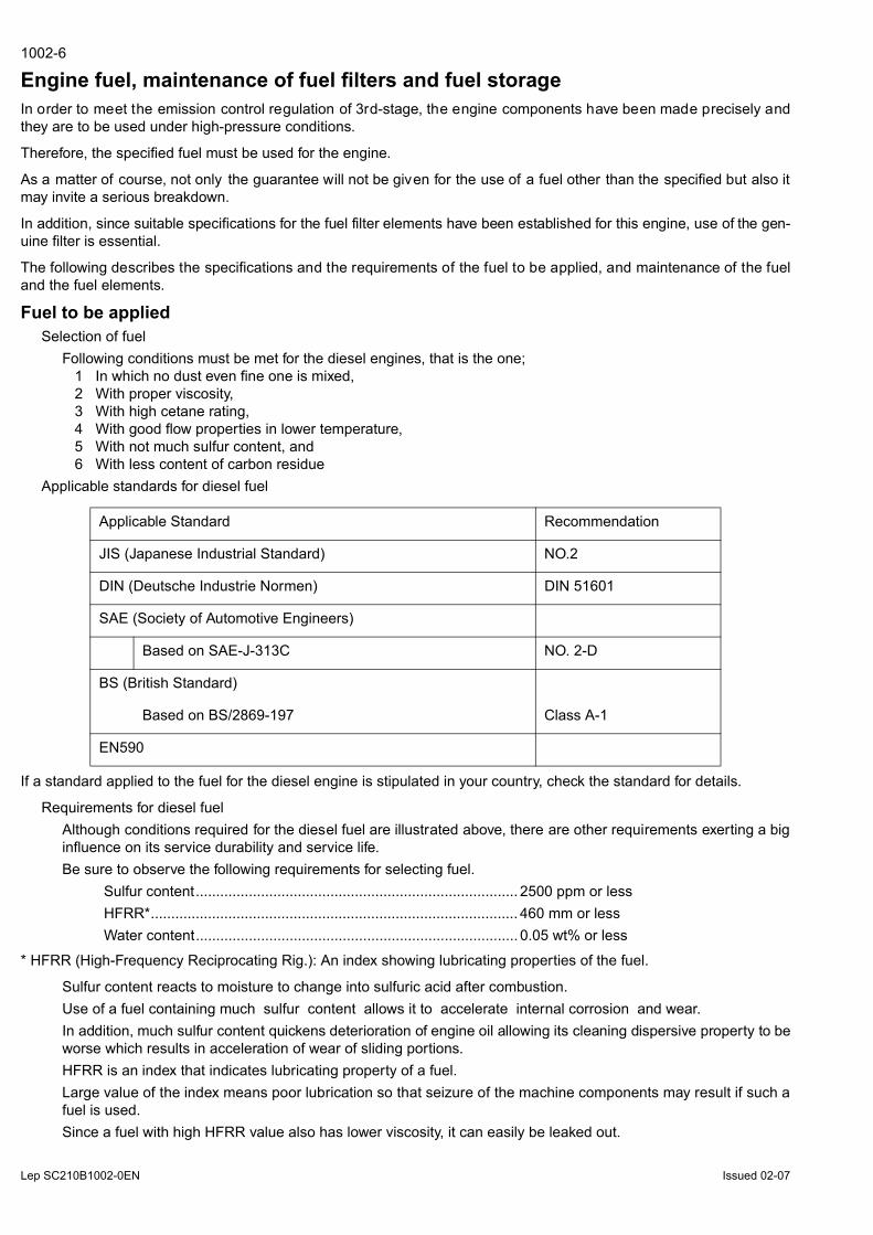
Engine fuel, maintenance of fuel filters and fuel storageIn order to meet the emission control regulation of 3rd-stage, the engine components have been made precisely andthey are to be used under high-pressure conditions.
Therefore, the specified fuel must be used for the engine.
As a matter of course, not only the guarantee will not be given for the use of a fuel other than the specified but also itmay invite a serious breakdown.
In addition, since suitable specifications for the fuel filter elements have been established for this engine, use of the gen-uine filter is essential.
The following describes the specifications and the requirements of the fuel to be applied, and maintenance of the fueland the fuel elements.
Fuel to be appliedSelection of fuel
Following conditions must be met for the diesel engines, that is the one;1 In which no dust even fine one is mixed,2 With proper viscosity,3 With high cetane rating,4 With good flow properties in lower temperature,5 With not much sulfur content, and6 With less content of carbon residue
Applicable standards for diesel fuel
If a standard applied to the fuel for the diesel engine is stipulated in your country, check the standard for details.
Requirements for diesel fuelAlthough conditions required for the diesel fuel are illustrated above, there are other requirements exerting a biginfluence on its service durability and service life.Be sure to observe the following requirements for selecting fuel.
Sulfur content............................................................................... 2500 ppm or lessHFRR*.......................................................................................... 460 mm or lessWater content............................................................................... 0.05 wt% or less
* HFRR (High-Frequency Reciprocating Rig.): An index showing lubricating properties of the fuel.
Sulfur content reacts to moisture to change into sulfuric acid after combustion.Use of a fuel containing much sulfur content allows it to accelerate internal corrosion and wear.In addition, much sulfur content quickens deterioration of engine oil allowing its cleaning dispersive property to beworse which results in acceleration of wear of sliding portions.HFRR is an index that indicates lubricating property of a fuel.Large value of the index means poor lubrication so that seizure of the machine components may result if such afuel is used.Since a fuel with high HFRR value also has lower viscosity, it can easily be leaked out.
Applicable Standard Recommendation
JIS (Japanese Industrial Standard) NO.2
DIN (Deutsche Industrie Normen) DIN 51601
SAE (Society of Automotive Engineers)
Based on SAE-J-313C NO. 2-D
BS (British Standard)
Based on BS/2869-197 Class A-1
EN590
Lep SC210B1002-0EN Issued 02-07
1002-7
If the fuel is mixed with the engine oil, the oil is diluted to deteriorate its lubricating property resulting in accelera-tion of wear.Water content allows inside of the fuel tank to rust which in turn blocking the fuel line and the fuel filter.
IMPORTANT : In cold weather, fill the fuel tank at the end of the day's work, in order to prevent the formation of conden-sation.
This may also cause wear and seizure of the machine components.If atmospheric temperature goes below the freezing point, moisture content in the fuel forms fine particle of iceallowing the fuel line to be clogged.
IMPORTANT : Obtain table of analysis for the fuel you are using from the fuel supplier to confirm that it meets the crite-ria described above.
IMPORTANT : If a fuel which does not meet the specifications and the requirements for the diesel engine, function andperformance of the engine will not be delivered. In addition, never use such a fuel because a breakdown of the engineor an accident may be invited.
Guarantee will not be given to a breakdown caused by the use of a improper fuel.Some fuels are used with engine oil or additives mixed together with diesel engine fuel.In this case, do not use these fuels because damage to the engine may result as the fuel has been contaminated.It is natural that the emission control regulation of 3rd-stage will not be cleared in case where a fuel that does notmeet the specifications and the requirements is used.Use the specified fuel for compliance of the exhaust gas control.
IMPORTANT : It you use diesel fuel which contains much sulfur content more than 2500 ppm, be sure to fol- low theitems below for the engine oil selection and maintenance of engine parts. Guarantee will not be given to breakdownscaused by not to follow these items.
1 Selection of engine oilUse API grade CF-4 or JASO grade DH-1.
2 Exchange the engine oil and engine oil f ilter element by the periodical interval reported on t he Operator’sManual.3 Inspect and exchange the EGR (*)parts and fuel injector parts of engine every 3000 hour of use.
* EGR: Exhaust Gas Recircultion
Maintenance of fuel filtersBe sure to use the genuine fuel filters.
The fuel injection system is precisely constructed and the genuine filter employs finer mesh than conventional fil-ters to improve protection of machine equipment.If a filter with coarse mesh is used, foreign object passing through the filter enters into the engine so that machineequipment can wear out in a short period of time.
IMPORTANT : If a fuel filter other than the genuine filter is used, guaranty will not be applied to a fault caused by theuse of a wrong filter.
Two kinds of fuel filter, the pre-filter and the main filter, are mounted on the machine.Be sure to use the genuine fuel filters and replace them at the periodic intervals reported on the operator’s Man-ual.
IMPORTANT : Since the pre-filter also has a function of water separation, discharge water and sediment when the floatreaches lower part of the filter elements. CHECK EVERY DAY before to start the engine.
Time to replace filters may be advanced according to properties of the fuel being supplied.• Therefore, take measures to prevent dust or water from being entered in the fuel tank when sup- plying fuel.• When supplying fuel directly from a fuel drum can, leave the drum as it stands for a long period of time to supplyclean fuel standing above a precipitate.• If it is hard to leave the drum for a long period of time, install a fuel strainer and a water separator before the fueltank of the machine to supply clean fuel.
Water drain cock is provided on the bottom side of the fuel tank.• Drain water before starting the engine every morning.• In addition, remove the cover under the tank once a year to clean up inside of the tank.
Lep SC210B1002-0EN Issued 02-07
1002-8
Fuel storageLong sto rage can lead to t he accumulation of impurities and condensation in t he f uel. Engine trouble can often betraced to the presence of water in the fuel.
The storage tank must be placed outside and the temperature of the fuel should be kept as low as possible. Drain offwater and impurities regularly.
Anti-freeze/Anti-corrosionUse anti-freeze in all seasons to protect the cooling system from corrosion and all risk of freezing.
CASE/AKCELA: PREMIUM ANTI-FREEZE (MS 1710)
For areas where the temperature goes down to -38°C (-36.4°F), mix 50/50 with water.
IMPORTANT : Do not mix products of a different origin or brand. The same product must be used when topping up thesystem.
EnvironmentBefore carrying out a ny maintenance o peration on t his ma chine an d b efore disposing o f used f luids o r lubricants,always think of the environment. Never throw oil or fluid on the ground and never place it in leaking receptacles.
Contact your local ecological recycling centre or your CASE Dealer to obtain information on the correct method of dis-posing of these lubricants.
Plastic and resin partsWhen cleaning plastic parts, the console, the instrument panel, the indicators etc... avoid using petrol, kerosene, paintsolvents etc... Use only water, soap and a soft cloth.
The use of petrol, kerosene, paint solvents etc... causes discoloration, cracks or deformation of these parts.

Lep SC210B1002-0EN Issued 02-07
1002-9
SPECIFICATIONS Main dataModel name
CX210B (LC, NLC and LR type), CX230B (NLC type) and CX240B (LC, NLC and LR type) Hydraulic ExcavatorOperating weight
CX210B (standard boom, LC type)...............................................................................................21200 kg (46738 lbs)CX210B (articulated boom, LC type)............................................................................................21450 kg (47289 lbs)CX210B (standard boom, NLC type) ............................................................................................21350 kg (47069 lbs)CX210B (articulated boom, NLC type) .........................................................................................22200 kg (48943 lbs)CX210B (LR type).........................................................................................................................22300 kg (49163 lbs)CX230B (standard boom, NLC type) ............................................................................................22700 kg (50045 lbs)CX230B (articulated boom, NLC type) .........................................................................................23550 kg (51919 lbs)CX240B (LC type).........................................................................................................................24500 kg (54014 lbs)CX240B (NLC type) ......................................................................................................................24400 kg (53793 lbs)CX240B (LR type).........................................................................................................................28000 kg (61730 lbs)
Engine outputCX210B, CX230B ......................................................................................................................... 117.3 kW / 1800 rpmCX240B ........................................................................................................................................ 132.1 kW / 2000 rpm
PerformanceSwing speed
CX210B, CX230B ........................................................................................................................................11.5 Tr/min.CX240B .......................................................................................................................................................10.7 Tr/min.
Travel speedCX210B ...................................................................................................................... Low Speed 3.4 km/h (2.11 mph)CX230B ...................................................................................................................... Low Speed 3.2 km/h (1.99 mph)CX240B ...................................................................................................................... Low Speed 3.5 km/h (2.17 mph)CX210B ......................................................................................................................High Speed 5.6 km/h (3.48 mph)CX230B ......................................................................................................................High Speed 5.0 km/h (3.11 mph)CX240B ......................................................................................................................High Speed 5.5 km/h (3.42 mph)
Maximum drawbar pullCX210B, CX230B ..................................................................................................................... 189.2 kN (42533.85 lbf)CX240B ......................................................................................................................................... 201 kN (45186.6 lbf)
Grade ability ........................................................................................................................................................70% (35°)Ground pressure
CX210B (standard boom, LC, NLC type)...................................................... 43 kPa (600 mm (23.62 in) grouser shoe)CX210B (standard boom, LC type)............................................................... 37 kPa (700 mm (27.56 in) grouser shoe)CX210B (standard boom, LC type), CX210B (LR type) ............................... 36 kPa (800 mm (31.50 in) grouser shoe)CX210B (standard boom, NLC type) ............................................................ 53 kPa (500 mm (19.68 in) grouser shoe)CX210B (articulated boom, LC type)............................................................ 45 kPa (600 mm (23.62 in) grouser shoe)CX210B (articulated boom, NLC type) ......................................................... 55 kPa (500 mm (19.68 in) grouser shoe)CX210B (articulated boom, NLC type) ......................................................... 46 kPa (600 mm (23.62 in) grouser shoe)CX230B (standard boom) ............................................................................. 54 kPa (550 mm (21.65 in) grouser shoe)CX230B (articulated boom) .......................................................................... 56 kPa (550 mm (21.65 in) grouser shoe)CX240B (LC, NLC type)................................................................................ 48 kPa (600 mm (23.62 in) grouser shoe)CX240B (LC type)......................................................................................... 42 kPa (700 mm (27.56 in) grouser shoe)CX240B (LC type)......................................................................................... 37 kPa (800 mm (31.50 in) grouser shoe)CX240B (LR type)......................................................................................... 42 kPa (800 mm (31.50 in) grouser shoe)

Lep SC210B1002-0EN Issued 02-07
1002-10
Complete machine dimensions
CX210B (LC type, standard boom)Arm (dipper)
2940 mm(115.75 in)
1900 mm(74.80 in)
2400 mm(94.49 in)
Lenght (without attachment) 4955 mm(195.08 in)
4955 mm(195.08 in)
4955 mm(195.08 in)
Lenght (with attachment) 9400 mm(370.08 in)
9490 mm(373.62 in)
9480 mm(373.23 in)
Height (with attachment) 2970 mm(116.93 in)
3090 mm(121.65 in)
3190 mm(125.59 in)
CX210B (LC type, articulated boom)Arm (dipper)
2940 mm(115.75 in)
1900 mm(74.80 in)
2400 mm(94.49 in)
Lenght (without attachment) 4955 mm(195.08 in)
4955 mm(195.08 in)
4955 mm(195.08 in)
Lenght (with attachment) 9400 mm(370.08 in)
9470 mm(372.83 in)
9455 mm(372.24 in)
Height (with attachment) 2960 mm(116.53 in)
2960 mm(116.53 in)
3035 mm(119.49 in)
CX210B (NLC type, standard boom)Arm (dipper)
2940 mm(115.75 in)
1900 mm(74.80 in)
2400 mm(94.49 in)
Lenght (without attachment) 5055 mm(199.01 in)
5055 mm(199.01 in)
5055 mm(199.01 in)
Lenght (with attachment) 9500 mm(374.01 in)
9590 mm(377.56 in)
9590 mm(377.5 in)
Height (with attachment) 2990 mm(117.72 in)
3090 mm(121.65 in)
3200 mm(125.98 in)
CX210B (NLC type, articulated boom)Arm (dipper)
2940 mm(115.75 in)
1900 mm(74.80 in)
2400 mm(94.49 in)
Lenght (without attachment) 5055 mm(199.01 in)
5055 mm(199.01 in)
5055 mm(199.01 in)
Lenght (with attachment) 9500 mm(374.01 in)
9570 mm(376.77 in)
9560 mm(376.38 in)
Height (with attachment) 2990 mm(117.72 in)
2990 mm(117.72 in)
3035 mm(119.49 in)
CX210B (LR type)Arm (dipper)
6400 mm(251.97 in)
Lenght (without attachment) 4950 mm(194.88 in)
Lenght (with attachment) 12470 mm(490.94 in)
Height (with attachment) 3000 mm(118.11 in)

Lep SC210B1002-0EN Issued 02-07
1002-11
CX230B (Standard boom)Arm (dipper)
2940 mm(115.75 in)
1900 mm(74.80 in)
2400 mm(94.49 in)
Lenght (without attachment) 4945 mm(194.68 in)
4945 mm(194.68 in)
4945 mm(194.68 in)
Lenght (with attachment) 9490 mm(373.62 in)
9570 mm(376.77 in)
9580 mm(377.16 in)
Height (with attachment) 3020 mm(118.90 in)
3110 mm(122.44 in)
3200 mm(125.98 in)
CX230B (Articulated boom)Arm (dipper)
2940 mm(115.75 in)
1900 mm(74.80 in)
2400 mm(94.49 in)
Lenght (without attachment) 4945 mm(194.68 in)
4945 mm(194.68 in)
4945 mm(194.68 in)
Lenght (with attachment) 9495 mm(373.82 in)
9565 mm(376.57 in)
9560 mm(376.77 in)
Height (with attachment) 3020 mm(118.90 in)
3020 mm(118.90 in)
3045 mm(119.88 in)
CX240B (LC type)Arm (dipper)
3000 mm(118.11 in)
2500 mm(98.42 in)
3520 mm(138.58 in)
Lenght (without attachment) 5270 mm(207.48 in)
5270 mm(207.48 in)
5270 mm(207.48 in)
Lenght (with attachment) 9930 mm(390.94 in)
9980 mm(392.91 in)
9910 mm(390.16 in)
Height (with attachment) 3150 mm(124.02 in)
3310 mm(130.31 in)
3310 mm(130.31 in)
CX240B (NLC type)Arm (dipper)
3000 mm(118.11 in)
2500 mm(98.42 in)
3520 mm(138.58 in)
Lenght (without attachment) 5265 mm(207.28 in)
5265 mm(207.28 in)
5265 mm(207.28 in)
Lenght (with attachment) 9930 mm(390.94 in)
9980 mm(392.91 in)
9910 mm(390.16 in)
Height (with attachment) 3150 mm(124.02 in)
3310 mm(130.31 in)
3310 mm(130.31 in)
CX240B (LR type)Arm (dipper)
8000 mm(314.96 in)
Lenght (without attachment) 5265 mm(207.28 in)
Lenght (with attachment) 14380 mm(566.14 in)
Height (with attachment) 3130 mm(123.23 in)
Lep SC210B1002-0EN Issued 02-07
1002-12
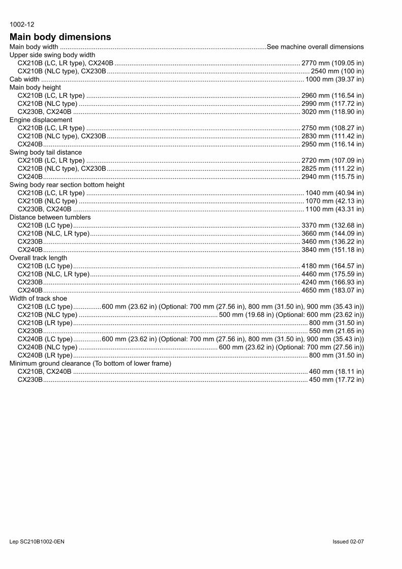
Main body dimensionsMain body width ..............................................................................................................See machine overall dimensionsUpper side swing body width
CX210B (LC, LR type), CX240B ................................................................................................... 2770 mm (109.05 in)CX210B (NLC type), CX230B............................................................................................................ 2540 mm (100 in)
Cab width ............................................................................................................................................ 1000 mm (39.37 in)Main body height
CX210B (LC, LR type) .................................................................................................................. 2960 mm (116.54 in)CX210B (NLC type) ...................................................................................................................... 2990 mm (117.72 in)CX230B, CX240B ......................................................................................................................... 3020 mm (118.90 in)
Engine displacementCX210B (LC, LR type) .................................................................................................................. 2750 mm (108.27 in)CX210B (NLC type), CX230B....................................................................................................... 2830 mm (111.42 in)CX240B......................................................................................................................................... 2950 mm (116.14 in)
Swing body tail distanceCX210B (LC, LR type) .................................................................................................................. 2720 mm (107.09 in)CX210B (NLC type), CX230B....................................................................................................... 2825 mm (111.22 in)CX240B......................................................................................................................................... 2940 mm (115.75 in)
Swing body rear section bottom heightCX210B (LC, LR type) .................................................................................................................... 1040 mm (40.94 in)CX210B (NLC type) ........................................................................................................................ 1070 mm (42.13 in)CX230B, CX240B ........................................................................................................................... 1100 mm (43.31 in)
Distance between tumblersCX210B (LC type) ......................................................................................................................... 3370 mm (132.68 in)CX210B (NLC, LR type)................................................................................................................ 3660 mm (144.09 in)CX230B......................................................................................................................................... 3460 mm (136.22 in)CX240B......................................................................................................................................... 3840 mm (151.18 in)
Overall track lengthCX210B (LC type) ......................................................................................................................... 4180 mm (164.57 in)CX210B (NLC, LR type)................................................................................................................ 4460 mm (175.59 in)CX230B......................................................................................................................................... 4240 mm (166.93 in)CX240B......................................................................................................................................... 4650 mm (183.07 in)
Width of track shoeCX210B (LC type) ...............600 mm (23.62 in) (Optional: 700 mm (27.56 in), 800 mm (31.50 in), 900 mm (35.43 in))CX210B (NLC type) .......................................................................... 500 mm (19.68 in) (Optional: 600 mm (23.62 in))CX210B (LR type) ............................................................................................................................. 800 mm (31.50 in)CX230B............................................................................................................................................. 550 mm (21.65 in)CX240B (LC type) ...............600 mm (23.62 in) (Optional: 700 mm (27.56 in), 800 mm (31.50 in), 900 mm (35.43 in))CX240B (NLC type) .......................................................................... 600 mm (23.62 in) (Optional: 700 mm (27.56 in))CX240B (LR type) ............................................................................................................................. 800 mm (31.50 in)
Minimum ground clearance (To bottom of lower frame)CX210B, CX240B ............................................................................................................................. 460 mm (18.11 in)CX230B............................................................................................................................................. 450 mm (17.72 in)

Lep SC210B1002-0EN Issued 02-07
1002-13
EngineName.......................................................................................................................................................... ISUZU, 4HK1XType: ........................................................4-cycle, water-cooled, overhead camshaft, vertical in-line, direct injection type............................................................................................................................... (electronic control), with turbocharger.No. of cylinders - bore x stroke.......................................................................... 4 - Ø115 mm x 125 mm (Ø4.53 x 4.92 in)Displacement ....................................................................................................................................... 5.193 L (1.372 gal)Compression ratio ........................................................................................................................................................17.5Rated output
CX210B, CX230B ....................................................................................................................... 117.3 kW / 1800 min-1
CX240B ...................................................................................................................................... 132.1 kW / 2000 min-1
Maximum torqueCX210B, CX230B ................................................................................................... 628 N.m (463.19 lb-ft) / 1500 min-1
CX240B .................................................................................................................. 636 N.m (469.09 lb-ft) / 1500 min-1
Engine dimensions (LxWxH).................................................................. 1020.4x829x1011.8 mm (40.17x32.64x39.83 in)Oil pan.......................................................................................................................................All direction 35°, inclinableOil pan capacity............................................... Maximum: 20.5 L (5.42 gal) Minimum: 13 L (3.43 gal) (excluding oil filter) Direction of rotation .............................................................................................................. Clockwise (as seen from fan)Starter, reduction type........................................................................................................................................24 V, 5 kWAlternator, AC type............................................................................................................................................. 24 V, 50 ABattery..................................................................................................................................................2 x 12V, 92 Ah/5 Hr
Cooling systemFan type ..........................................Ø 650 mm (25.59 in), suction type - 7 blades, plastic with belt mouth-type fan guidePulley ratio ................................................................................................................................................ 0.85 (reduction)Radiator
Fin type ...................................................................................................................................................................wavyFin pitch ............................................................................................................................................. 2.0 mm (0.078 in)
Oil coolerFin type ...................................................................................................................................................................wavyFin pitch ........................................................................................................................................... 1.75 mm (0.069 in)
Inter-coolerFin type ............................................................................................................................................... triangular straightFin pitch ........................................................................................................................................... 1.75 mm (0.069 in)
Fuel coolerFin type ...................................................................................................................................................................wavyFin pitch ............................................................................................................................................. 2.0 mm (0.078 in)
Coolant capacity.....................................................................................................................14 L (3.70 gal) (engine only)
Capacity of coolant and lubricantsCoolant
CX210B, CX230B ................................................................................................................................ 25.6 L (6.76 gal)CX240B ............................................................................................................................................... 25.2 L (6.66 gal)
Fuel ....................................................................................................................................................... 410 L (108.31 gal)Lubricant for engine ................................................................................................................................... 23.1 L (6.1 gal)Lubricant for travel reduction gear (per side) ............................................................................................. 5.0 L (1.32 gal)Lubricant for swing reduction gear (per side)
CX210B, CX230B .................................................................................................................................. 5.0 L (1.32 gal)CX240B ................................................................................................................................................. 9.7 L (2.56 gal)
Hydraulic oilCX210B, CX230B ............................................................................................................................... 240 L (63.40 gal)CX240B .............................................................................................................................................. 250 L (66.04 gal)
Capacity of hydraulic oil tank .................................................................................................................. 147 L (38.83 gal)
Lep SC210B1002-0EN Issued 02-07
1002-14
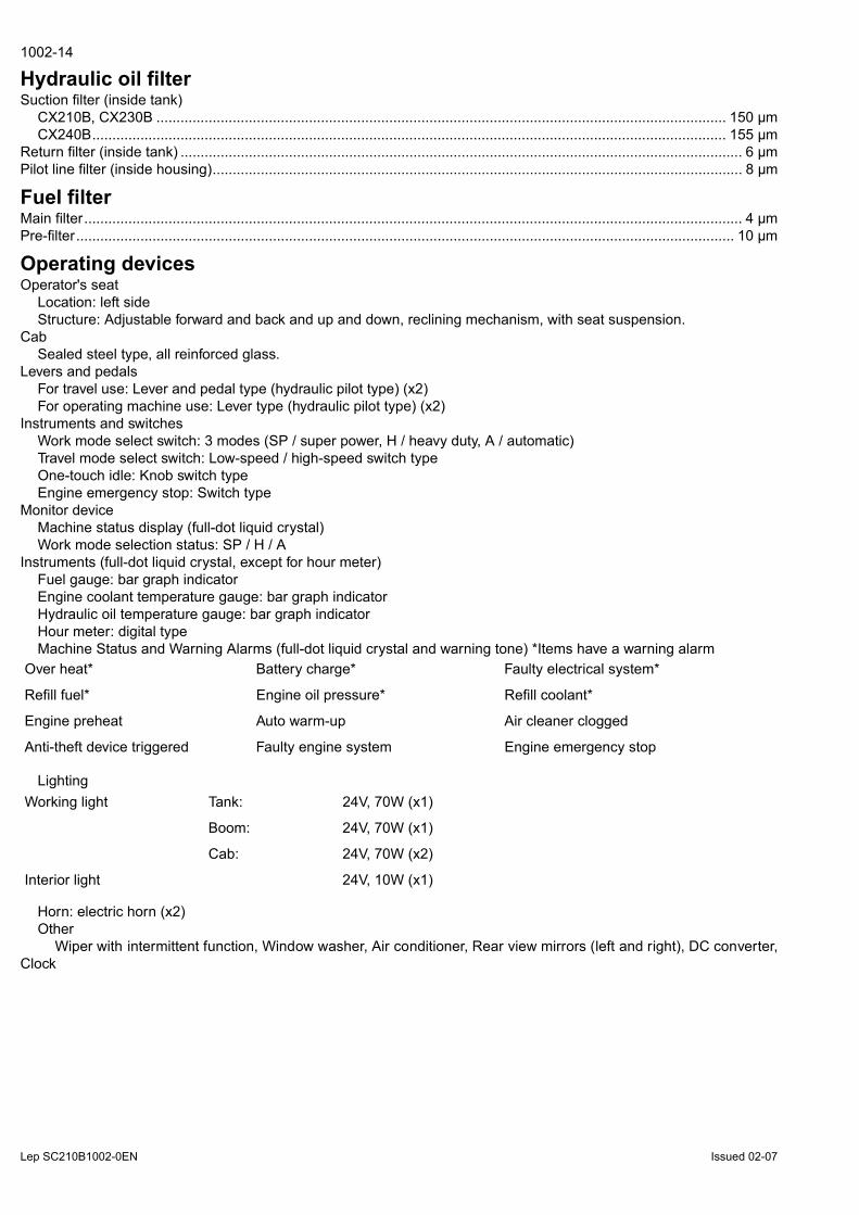
Hydraulic oil filterSuction filter (inside tank)
CX210B, CX230B .............................................................................................................................................. 150 µmCX240B.............................................................................................................................................................. 155 µm
Return filter (inside tank) ............................................................................................................................................ 6 µmPilot line filter (inside housing).................................................................................................................................... 8 µm
Fuel filterMain filter.................................................................................................................................................................... 4 µmPre-filter.................................................................................................................................................................... 10 µm
Operating devicesOperator's seat
Location: left sideStructure: Adjustable forward and back and up and down, reclining mechanism, with seat suspension.
CabSealed steel type, all reinforced glass.
Levers and pedalsFor travel use: Lever and pedal type (hydraulic pilot type) (x2)For operating machine use: Lever type (hydraulic pilot type) (x2)
Instruments and switchesWork mode select switch: 3 modes (SP / super power, H / heavy duty, A / automatic)Travel mode select switch: Low-speed / high-speed switch typeOne-touch idle: Knob switch typeEngine emergency stop: Switch type
Monitor deviceMachine status display (full-dot liquid crystal)Work mode selection status: SP / H / A
Instruments (full-dot liquid crystal, except for hour meter) Fuel gauge: bar graph indicatorEngine coolant temperature gauge: bar graph indicatorHydraulic oil temperature gauge: bar graph indicatorHour meter: digital typeMachine Status and Warning Alarms (full-dot liquid crystal and warning tone) *Items have a warning alarm
Lighting
Horn: electric horn (x2)Other
Wiper with intermittent function, Window washer, Air conditioner, Rear view mirrors (left and right), DC converter,Clock
Over heat* Battery charge* Faulty electrical system*
Refill fuel* Engine oil pressure* Refill coolant*
Engine preheat Auto warm-up Air cleaner clogged
Anti-theft device triggered Faulty engine system Engine emergency stop
Working light Tank: 24V, 70W (x1)
Boom: 24V, 70W (x1)
Cab: 24V, 70W (x2)
Interior light 24V, 10W (x1)

Lep SC210B1002-0EN Issued 02-07
1002-15
Hydraulic systemHydraulic pump drive system, directly coupled to the engine (no transmission)
Main pumpManufacturer .............................................................................................................................................. KawasakiPump type ..............................................................................................double variable displacement piston pumpDisplacement volume .................................................................................................118.5 cm3 (7.23 cu in) x 2 /revRated operating pressure.......................................................................................................... 34.3 MPa (4975 psi)Maximum operating pressure .................................................................................................... 36.8 MPa (5337 psi)Input revolution speed
CX210B, CX230B ................................................................................................................................1800 min-1CX240B................................................................................................................................................2000 min-1
Maximum discharge flowCX210B, CX230B ................................................................................. 211 L/min (55.74 gpm) x 2 at 1800 min-1
CX240B................................................................................................. 234 L/min (61.82 gpm) x 2 at 2000 min-1
Pilot pumpPump type ...............................................................................................................................................Gear pumpDisplacement volume .............................................................................................................10 cm3 (0.61 cu in)/revOperating pressure...................................................................................................................... 3.92 MPa (568 psi)Maximum flow
CX210B, CX230B .........................................................................................18 L/min (4.75 gpm) (at 1800 min-1)CX240B.........................................................................................................20 L/min (5.28 gpm) (at 2000 min-1)
Control methodHydraulic simultaneous constant output control.Maximum flow adjustment control through external commands (negative control).Setting horsepower adjustment control through external command current.
Control ValveModel; 4-spool section: integrated (1) or 5-spool section: integrated (1)Operation method: hydraulic pilot method: travel, swing and operating machine Maximum flow
CX210B, CX230B..........................................................................................213 L/min (52.27 gpm) (at 1800 min-1)CX240B .........................................................................................................237 L/min (62.61 gpm) (at 2000 min-1)
Main relief set pressure ...........................................standard; 34.3 MPa (4975 psi), power boost 36.8 MPa (5337 psi)Overload set pressure
CX210B (LR type).................................................................................................................................. bucket; 25.0 MPa (3626 psi).................................................................................................................................. arm in; 23.0 MPa (3336 psi)
CX240B (LR type).................................................................................................................................. bucket; 29.4 MPa (4264 psi)............................................................................................................................... arm in; 21.1.0 MPa (3060 psi)
All................................................................................................................ when boom down; 29.4 MPa (4264 psi).................................................................................................................................... other: 38.7 MPa (5613 psi)
Foot relief set pressure ............................................................................................................... 2.55 MPa (369.85 psi)Functions
Straight travel circuitBoom up / arm 2 pumps internal flowBoom and arm load holding circuitBoom-down regenerative circuitBucket-close regenerative circuitArm-in forced regenerative circuitSwing priority variable orifice (for arm operation)2 pumps flowVariable foot relief

Lep SC210B1002-0EN Issued 02-07
1002-16
Hydraulic CylindersBoom cylinder (x2)
CX210B, CX230BCylinder bore .........................................................................................................................Ø120 mm (Ø4.72 in)Rod diametre...........................................................................................................................Ø85 mm (Ø3.35 in)Maximum retracted lenghth .................................................................................................... 1753 mm (69.02 in)Stroke ..................................................................................................................................... 1255 mm (49.41 in)
CX240BCylinder bore .........................................................................................................................Ø130 mm (Ø5.12 in)Rod diametre...........................................................................................................................Ø90 mm (Ø3.54 in)Maximum retracted lenghth .................................................................................................... 1855 mm (73.03 in)Stroke ..................................................................................................................................... 1335 mm (52.56 in)
Articulated boom cylinderCX210B, CX230B
Cylinder bore .........................................................................................................................Ø150 mm (Ø5.90 in)Rod diametre.........................................................................................................................Ø100 mm (Ø3.94 in)Maximum retracted lenghth .................................................................................................... 1570 mm (61.81 in)Stroke ..................................................................................................................................... 1090 mm (42.91 in)
Arm (dipper) cylinderCX210B (LC, NLC type), CX230B
Cylinder bore .........................................................................................................................Ø140 mm (Ø5.51 in)Rod diametre.........................................................................................................................Ø100 mm (Ø3.94 in)Maximum retracted lenghth .................................................................................................... 2020 mm (79.53 in)Stroke ..................................................................................................................................... 1460 mm (57.48 in)
CX210B (LR type)Cylinder bore .........................................................................................................................Ø145 mm (Ø5.71 in)Rod diametre.........................................................................................................................Ø105 mm (Ø4.13 in)Maximum retracted lenghth .................................................................................................... 2205 mm (86.81 in)Stroke ..................................................................................................................................... 1627 mm (64.05 in)
CX240B (LC, NLC type)Cylinder bore .........................................................................................................................Ø145 mm (Ø5.71 in)Rod diametre.........................................................................................................................Ø105 mm (Ø4.13 in)Maximum retracted lenghth .................................................................................................... 2240 mm (88.19 in)Stroke ..................................................................................................................................... 1660 mm (65.35 in)
CX240B (LR type)Cylinder bore .........................................................................................................................Ø150 mm (Ø5.90 in)Rod diametre.........................................................................................................................Ø105 mm (Ø4.13 in)Maximum retracted lenghth .................................................................................................... 2425 mm (95.47 in)Stroke ..................................................................................................................................... 1737 mm (68.39 in)
Bucket cylinderCX210B (LC, NLC type), CX230B
Cylinder bore .........................................................................................................................Ø120 mm (Ø4.72 in)Rod diametre...........................................................................................................................Ø85 mm (Ø3.35 in)Maximum retracted lenghth .................................................................................................... 1565 mm (61.61 in)Stroke ..................................................................................................................................... 1010 mm (39.76 in)
CX240B (LC, NLC type)Cylinder bore .........................................................................................................................Ø130 mm (Ø5.12 in)Rod diametre...........................................................................................................................Ø90 mm (Ø3.54 in)Maximum retracted lenghth .................................................................................................... 1635 mm (64.37 in)Stroke ..................................................................................................................................... 1070 mm (42.13 in)
CX210B (LR type), CX240B (LR type)Cylinder bore ...........................................................................................................................Ø95 mm (Ø3.74 in)Rod diametre...........................................................................................................................Ø65 mm (Ø2.56 in)Maximum retracted lenghth .................................................................................................... 1373 mm (54.05 in)Stroke ....................................................................................................................................... 881 mm (34.68 in)

BUY NOW Then Instant Download
the Complete Manual
Thank you very much!


