
CRANE MODERNIZATION – WHY AND HOW? · corrosion. Fatigue cracks however do occur along the way as...
27
PORT K Crane Modernisation-TOCASIA1998 v.2 Page 1 of 27 CRANE MODERNIZATION – WHY AND HOW? Presented at TOCASIA 1998 by Peter M. Darley – Technical Director & Jimmy Liang – Marketing Director 1.0 Introduction Crane modernisation refers to an exercise in which a crane is modified, refurbished or upgraded for the purpose of achieving improved productivity, increased reliability and safety, enhanced maintainability, or of overcoming difficulty in procuring obsolete spare parts. The scope of modernisation could include structural dimensional changes, mechanical system upgrades or electrical and drive control upgrades. This paper is written basically with reference to container handling cranes including the quay side cranes, rubber tyre gantry crane (RTGs) and rail mounted gantry cranes (RMGs) For the sake of differentiating between minor improvement and major upgrading exercises, we define a major crane upgrade as a job that carries a value of USD 400,000 and above. Such a value could conceivably cover a basic crane drive retrofit (without replacing the DC motors) or a span change or a main hoist drive train upgrade (such as replacement of gear boxes, brakes, couplings, rope reeving system, etc). 1.1 Crane Age Profile in Middle East / Indian Sub-Continent There are now close to 200 quay cranes operating in the Middle East / Indian Sub-continent region. The age profiles of these cranes are as follows: Year pre-1976 1976-80 1981-85 Post 1985 Total (units) Number in operation 9 35 34 118 196 Number requiring major upgrade 9 (at 100% of population ) 25 (at 70%) 17 (at 50%) 11 (at 10%) 62 Crane age profile data are extracted from “Containerization International Crane Age Profile” From the above table, an estimated 62 units of quay cranes are deemed to require some kind of major upgrade. Of course, if one takes into account minor upgrades such as change of operator cabin / console or change of drum brake to disc brake, then the number of cranes will be considerably larger than the 62 units estimated above.
Transcript of CRANE MODERNIZATION – WHY AND HOW? · corrosion. Fatigue cracks however do occur along the way as...

PORT K
Crane Modernisation-TOCASIA1998 v.2 Page 1 of 27
CRANE MODERNIZATION – WHY AND HOW? Presented at TOCASIA 1998 by Peter M. Darley – Technical Director & Jimmy Liang – Marketing Director 1.0 Introduction Crane modernisation refers to an exercise in which a crane is modified, refurbished or upgraded for the purpose of achieving improved productivity, increased reliability and safety, enhanced maintainability, or of overcoming difficulty in procuring obsolete spare parts. The scope of modernisation could include structural dimensional changes, mechanical system upgrades or electrical and drive control upgrades. This paper is written basically with reference to container handling cranes including the quay side cranes, rubber tyre gantry crane (RTGs) and rail mounted gantry cranes (RMGs) For the sake of differentiating between minor improvement and major upgrading exercises, we define a major crane upgrade as a job that carries a value of USD 400,000 and above. Such a value could conceivably cover a basic crane drive retrofit (without replacing the DC motors) or a span change or a main hoist drive train upgrade (such as replacement of gear boxes, brakes, couplings, rope reeving system, etc). 1.1 Crane Age Profile in Middle East / Indian Sub-Continent There are now close to 200 quay cranes operating in the Middle East / Indian Sub-continent region. The age profiles of these cranes are as follows: Year pre-1976 1976-80 1981-85 Post 1985
Total
(units)Number in operation
9 35 34 118 196
Number requiring major upgrade
9 (at 100% of population )
25 (at 70%)
17 (at 50%)
11 (at 10%)
62
Crane age profile data are extracted from “Containerization International Crane Age Profile” From the above table, an estimated 62 units of quay cranes are deemed to require some kind of major upgrade. Of course, if one takes into account minor upgrades such as change of operator cabin / console or change of drum brake to disc brake, then the number of cranes will be considerably larger than the 62 units estimated above.
PORT K
Crane Modernisation-TOCASIA1998 v.2 Page 2 of 27
1.2 Problems Associated with Crane Aging The economic life of a container quay crane is normally taken as twenty years. This is very commonly taken as the maximum depreciation or amortisation period. The actual life of a quay side container crane, in common with other large port cranes, is of course much more than this. Major hub ports around the World need to keep abreast of changing requirements of size of crane in line with the ever-increasing size of Container vessels. Other ports with navigation or other factors limiting the size of vessels, have no need to change the dimensional specifications of their cranes. Structural life of a container crane is easily in excess of 30 years, and could be 40 or more years, if the crane structures had been properly designed, maintained and protected against corrosion. Fatigue cracks however do occur along the way as the crane ages. In most cases, such fatigue cracks could be made good with proper failure analysis and repair method. However, to keep a Container Crane in efficient and economical working order for this period requires some consideration of the economic life of the major components. 1.2.1 Obsolescence The heart of a Container Quay Crane is the drive control system. The economic life of the drive control system is about 15 years figure. The technology, performance standards and reliability of drive control systems are continually evolving. After 15 years, changing technology and diminishing spare parts support makes the overall performance of the drive less than satisfactory to the user in comparison to what is available with new equipment. Less availability means less revenue and higher operating costs; more reliability means more revenue. 1.2.2 Availability of spare parts Availability of spare parts after 10-15 years is a particular problem. For example, because of rapidly developing technology in the field of electronic components, original or compatible printed circuit boards and their components may simply no longer be obtainable after this amount of time. Not all manufacturers will support availability of spare parts for their products for such a long period. Then crane downtime becomes a very serious economic factor. This is a very common problem that experienced users will recognise.
1.2.3 Operating Performance Operating performance should not be ignored either. Many older cranes are running with 35 m/min full load hoist speed as against 60 -70 m/min of newer cranes. Further, such cranes were designed without much consideration to proper ergonomics and operator comfort. Access to the cabin can be difficult and dangerous, operator cabin may not be

PORT K
Crane Modernisation-TOCASIA1998 v.2 Page 3 of 27
ergonomically designed. A few extra containers per hour (that may come with an upgrade) in average performance means more earning power. 1.2.4 Safety Safety is another issue. Older cranes were normally designed with less mechanical and electrical protection simply because the demand were less stringent in those times. For example, older main hoist systems have only one set of drum brake assembly instead of two sets of more reliable disc brakes commonly found in newer ones. Modern programmable logic controllers (PLC’s) and drive systems have built-in detection and interlocks which could prohibit many unsafe operation. No business can afford to stand still and watch its performance gradually reduce. What should the user do? The market price for a new crane is in the order of US $ 5 to 6 millions with a lead time of 14 to 18 months. If the original crane is still the right size and in the right place, a drive system upgrade, is an economically attractive and much faster solution to the dilemma. The idea of a Mid Life Upgrade for expensive capital equipment is not new. As well as installing the latest technology with lower operating costs and greater reliability, the performance and productivity of the crane can be significantly improved.

PORT K
Crane Modernisation-TOCASIA1998 v.2 Page 4 of 27
2.0 Modernization of Structural and Mechanical Systems 2.1 Structural Modifications / Geometry Changes In general major structural modifications to container cranes can be accomplished in much less time and cost than replacement with a new crane. The normal gestation period for a new crane, at 14-18 months is considerably longer than the 3-6 month gestation period for major structural alterations. 2.1.1 Boom Job - Outreach change Before entering the discussion on outreach change, perhaps the fundamental unit of container crane outreach, Panamax, should be clarified. The definition of Panamax is quite clear as applied to a container vessel. As applied to a container crane it should translate to an outreach of around 36 metres after allowance of the normal 2.5-3.5 m distance from seaside crane rail to quay fender face and adverse vessel list. However, "Containerisation International" in it's last market review quotes the following definitions:-
Outreach Standard Panamax 36 – 44m Post Panamax 44 – 48m Extra Post Panamax 48m and greater
The feasibility of change in outreach depends very much on the reserve factors built into the structure original design and wheel load capacity of the quay. When planning such a modification, various increases are possible, ranging from one, two or three container widths, each container width being 8 ft. A three container wide increase from a 36m Panamax outreach will increase boom weight by about 20% and load moment due to trolley, headblock and spreader will also increase by 20%.
Increased loads of this level will probably require considerable structural reinforcement and attendant increase in weight. The resultant modifications will tend to increase wheel loads, particularly on the seaside rail. It is technically possible to increase the number of bogie wheels to maintain wheel loads at the original figure. Additional ballast, applied in the correct place may be used to adjust stability and wheel loads. The effect of outreach change to load re-distribution will be less on wider rail gauge cranes.
Outreach changes have effects on boom hoist mechanisms. In cases of small incremental increase the boom hoist gear will probably be able to cope with extra weight, larger increases may entail upgrading of the boom hoist drive and/or reeving system.
The feasibility of an outreach modification depends on too many variables to make any general conclusion apart from the fact that it is likely to be expensive. However, compared with the cost and delivery time of a new crane, it may still be commercially viable.
PORT K
Crane Modernisation-TOCASIA1998 v.2 Page 5 of 27
2.1.2 Height Increase Increase of height of older cranes is often a feasible procedure. Older Panamax cranes with lift heights less than the preferred norm of around 27m lift height above rail can be economically raised to this level. Cranes of the late 1960’s and early 1970’s vintage normally would not have sufficient height to cope with even new feeder vessels. Height increase ranging from 3 m to 6.5 m had been carried out on such cranes.
Height increase involves modification to the leg structure to raise the height of the crane plus attendant changes to the hoist drum and hoist rope to accommodate the increased lift. 2.1.3 Span Changes Changes of rail span are often required when cranes are relocated from one terminal to another. The wide variety of rail gauges, seaside versus landside rail height differences, and rail types existent in terminals around the world requires some structural and mechanical modifications to adapt cranes to new locations. This can even be required when relocating a crane from one quay to another within the same port. Many terminals when opening new quays or quay extensions have opted for larger rail gauges to suit larger outreach cranes.
Crane span changes can be performed relatively quickly and economically by experienced specialist companies. Typically, the process can be completed in less than three months including design time. On-site work can be completed in less than two weeks. The process involves:- a) Design of modification and planning of procedure. Consideration of crane structure,
quay structure and method of support during modification process. b) Thorough design and structural analysis of modified crane to relevant stability and
structural design codes using finite element analysis c) Manufacture of any new fabricated structural elements and temporary support
structures. d) Mobilisation of parts and equipment to site.
e) Modification on site. f) Test and recommissioning.

PORT K
Crane Modernisation-TOCASIA1998 v.2 Page 6 of 27
Hitachi Crane in Sealand, Kaohsiung before Span Change (24.38 metres)
Hitachi Crane in Surabaya, Indonesia after Span Change (18 metres)

PORT K
Crane Modernisation-TOCASIA1998 v.2 Page 7 of 27
2.2 Brakes - General Brakes are a critical mechanism on the crane as it is directly in the line of force of the load. Brake failure often leads to catastrophic consequences. Hence, it is appropriate to discuss this subject at some length. Modern cranes use disc brakes on all functions because of the greater efficiency and emergency stopping power of disc brakes. The rotational speed and energy absorption of disc brakes is far higher than for drum brakes. Also lower lining wear rates and auto adjustment of disc brakes means less maintenance and greater safety. Electro-hydraulic thruster brake actuation gives much smoother brake operation without the mechanical shocks and electrical voltage transients of DC solenoid actuators. The high inrush current and voltage transient on spring return place great stress on the electrical components of the DC solenoid actuator system. This results in high maintenance costs and poorer reliability in comparison with an electro-hydraulic thruster actuator system. Total brake system changes from DC Solenoid drum brakes to electro-hydraulic thruster disc brake are viable and can be justified on the grounds of greater safety and economy of operation.
Electro-Hydraulic Thruster Disc Brake

PORT K
Crane Modernisation-TOCASIA1998 v.2 Page 8 of 27
2.2.1 Boom Hoist Brakes The latest generation hoist brake configuration is now being applied to the less arduous demands of boom hoist, where previous practice was to mount caliper or band brake on the rope drum as drum type shoe brake were not regarded as reliable enough on the motor output shaft. Although a boom hoist is much slower and less demanding than a main hoist, if the drive and brakes fail, the result can obviously be catastrophic. A double disc brake fitted to the high speed motor shaft is preferred instead of the current practice of emergency band or caliper brakes on the boom hoist winch. These are equipped with an automatic centering device to ensure equal wear for both pads as well as an automatic wear adjustment to ensure constant clearance gaps between the pads and the disc. Many spring applied boom hoist brakes in service are not equipped with automatic wear compensation. Automatic wear compensation is essential in spring applied brakes to avoid reduction of spring force as the linings wear. However, "brake are only as safe as the servicing and maintenance performed." Features such as these can reduce the maintenance requirements. 2.2.2 Gantry Travel Brakes Gantry travel brakes on many cranes are of the enclosed motor mounted multi plate disc brake type. These have very limited energy absorption capabilities in comparison with a separate caliper disc brake. Motor mounted brakes, being enclosed, suffer from poor heat dissipation and limited access to check adjustment and lining wear. One of the hazards of port crane operation is the effect of wind pressure on the crane structure. This is an important design consideration, both in terms of the structure and mechanisms to withstand the wind loads and for the crane operator to be able to take whatever precautions may be necessary. To be protected against wind gusts, even within the in-service wind speed limits, tile crane equipment, such as long travel wheel brakes, must be in good working order. Container crane accidents have been caused by the effect of strong gusts of wind (such as microburst) during normal operation. This problem has been reported quite frequently in the ports in Middle East. Cranes have been known to collapse as 'result of serious run-away accidents where the cantilever of the crane has collided with a ship's structure or the crane has simply overrun its track. In many cases the motor integrated disc brakes (sometimes these are multiple disc brakes, sometimes not) used to control gantry travel are not heavy duty brakes. New electronic control technology means that motor speeds can reach between 2000 and 3000 rpm. But conventional integral brakes alone, without motor power, are unable to absorb reliably the kinetic energy of a modern container quay crane moving at maximum speed, to say nothing of excess long travel speeds in a "run away" situation. Brake performance will quickly degrade as this type of light duty brake reaches its temperature limit. In many cases, storm

PORT K
Crane Modernisation-TOCASIA1998 v.2 Page 9 of 27
brakes (rail clamp devices) have been installed to compensate for this poor brake performance, but is this arrangement effective in real emergencies? Many types of rail clamp are not automatic, and require timely manual intervention to prevent a disaster. In practice, in many incidents, the crane has started moving out of control when the rail clamps were not engaged, and the primary motor brakes were subsequently found to be ineffective due to wear or poor adjustment. In practice, it often transpires that the rail clamp is a secondary braking device used to supplement an unreliable primary braking device. The heavy-duty, thruster-operated disc brake for gantry-installation on container cranes is a superior solution. A suitably selected disc brake can bring a gantry crane to a complete standstill in 25m/s following-wind conditions. The following picture shows thruster operated disc brakes installed in place of motor integrated disc brakes.
Gantry Thruster Disc Brake
The ability of this disc brake to stop the crane from full speed without the use of a motor can always be tested and confirmed at the time of commissioning. Vertically-installed disc brakes can be used on vertical axis flange-mounted motors as well as on horizontal axis motors. 2.2.3 Drive Couplings The problem with conventional gear couplings is that OEMs frequently cannot exercise proper quality control since they may be sourced by purchasing agents from a wide range of suppliers purely on a price basis. To check the condition of the gear teeth, the unit has to be dismantled, which is impractical. One recent case of a hoist failure leading to a container drop, which was ultimately traced to misalignment within the coupling. Flexible Rubber buffer couplings could be installed in place of gear couplings. Torque is
PORT K
Crane Modernisation-TOCASIA1998 v.2 Page 10 of 27
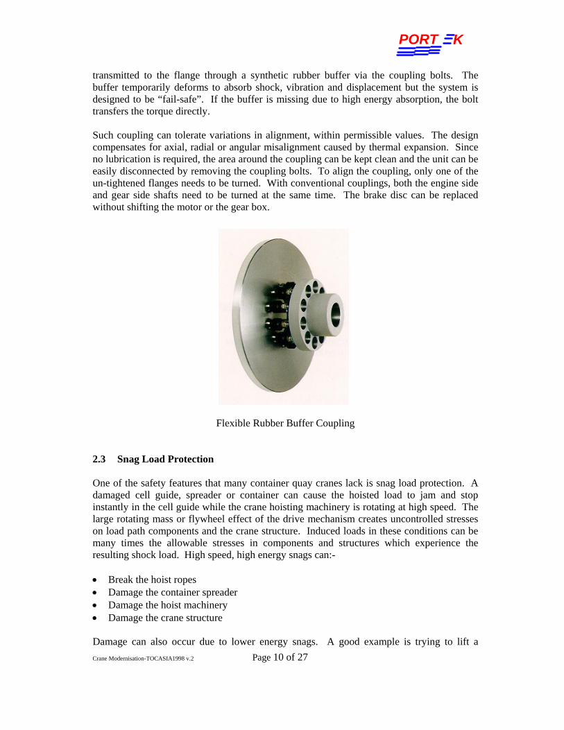
transmitted to the flange through a synthetic rubber buffer via the coupling bolts. The buffer temporarily deforms to absorb shock, vibration and displacement but the system is designed to be “fail-safe”. If the buffer is missing due to high energy absorption, the bolt transfers the torque directly. Such coupling can tolerate variations in alignment, within permissible values. The design compensates for axial, radial or angular misalignment caused by thermal expansion. Since no lubrication is required, the area around the coupling can be kept clean and the unit can be easily disconnected by removing the coupling bolts. To align the coupling, only one of the un-tightened flanges needs to be turned. With conventional couplings, both the engine side and gear side shafts need to be turned at the same time. The brake disc can be replaced without shifting the motor or the gear box.
Flexible Rubber Buffer Coupling
2.3 Snag Load Protection One of the safety features that many container quay cranes lack is snag load protection. A damaged cell guide, spreader or container can cause the hoisted load to jam and stop instantly in the cell guide while the crane hoisting machinery is rotating at high speed. The large rotating mass or flywheel effect of the drive mechanism creates uncontrolled stresses on load path components and the crane structure. Induced loads in these conditions can be many times the allowable stresses in components and structures which experience the resulting shock load. High speed, high energy snags can:- • Break the hoist ropes • Damage the container spreader • Damage the hoist machinery • Damage the crane structure Damage can also occur due to lower energy snags. A good example is trying to lift a
PORT K
Crane Modernisation-TOCASIA1998 v.2 Page 11 of 27
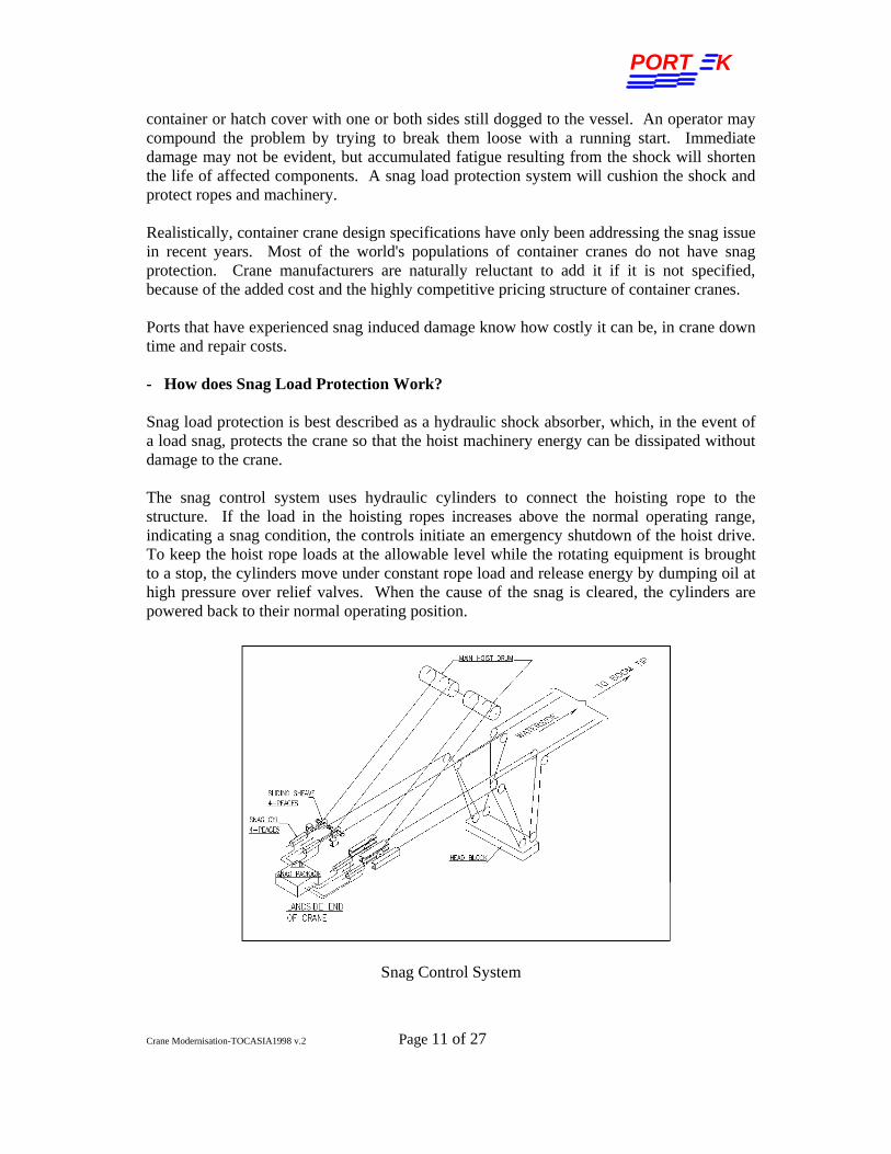
container or hatch cover with one or both sides still dogged to the vessel. An operator may compound the problem by trying to break them loose with a running start. Immediate damage may not be evident, but accumulated fatigue resulting from the shock will shorten the life of affected components. A snag load protection system will cushion the shock and protect ropes and machinery. Realistically, container crane design specifications have only been addressing the snag issue in recent years. Most of the world's populations of container cranes do not have snag protection. Crane manufacturers are naturally reluctant to add it if it is not specified, because of the added cost and the highly competitive pricing structure of container cranes. Ports that have experienced snag induced damage know how costly it can be, in crane down time and repair costs. - How does Snag Load Protection Work? Snag load protection is best described as a hydraulic shock absorber, which, in the event of a load snag, protects the crane so that the hoist machinery energy can be dissipated without damage to the crane. The snag control system uses hydraulic cylinders to connect the hoisting rope to the structure. If the load in the hoisting ropes increases above the normal operating range, indicating a snag condition, the controls initiate an emergency shutdown of the hoist drive. To keep the hoist rope loads at the allowable level while the rotating equipment is brought to a stop, the cylinders move under constant rope load and release energy by dumping oil at high pressure over relief valves. When the cause of the snag is cleared, the cylinders are powered back to their normal operating position.
Snag Control System

PORT K
Crane Modernisation-TOCASIA1998 v.2 Page 12 of 27
Snag load protection can be fitted to existing cranes. In order to complete a retrofit, it is necessary to conduct the following program:- • Engineering site visit to review the crane dynamics and snag protection requirements. • Design and detail installation of snag protection machinery. • Manufacture snag protection machinery and deliver to site. • Site modification of crane to accept snag protection machinery and installation of
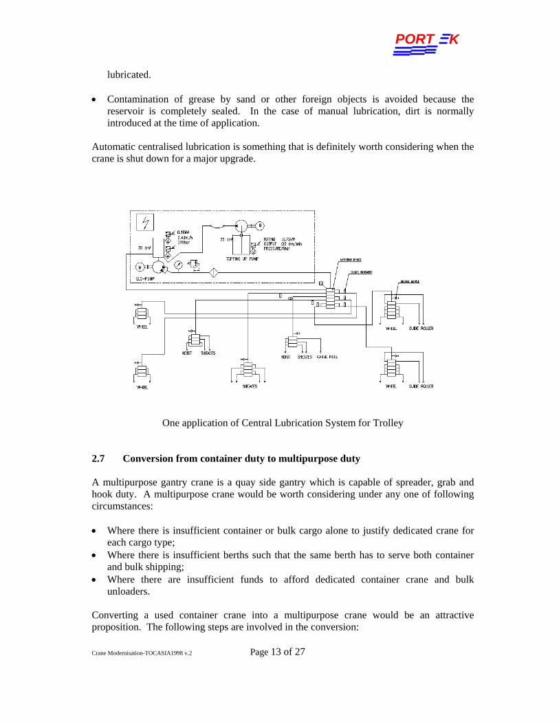
equipment and control modifications. • Testing and commissioning of new snag protection system. 2.4 Elevator Surprisingly, many container cranes still exist without elevators. Ease of access and safety are much improved for operators and technicians by the installation of an elevator. Hence, efficiency of personnel is much improved. Normally, crane elevators have rack and pinion PLC controlled drive and fail-safe brake. Multiple landing stations can be provided for intermediate stops at portal beam, for access to such things as main power cable reel, operator cabin level, and finally machinery house level. 2.5 Spreader interchangeability Most terminals have cranes of different brands and specifications which were acquired over a period of years. Such cranes normally come with different headblocks and spreaders which are often not interchangeable. At a rather modest cost, it is possible to modify the headblocks and spreaders so as to enable any of the spreaders to be used on any one of those cranes. Benefits of such interchangeability are: • considerable savings from not having to keep a large number of spare spreaders • crane downtime owing to non-availability of spreaders is now reduced The work scope involved in this exercise normally include some structural modification to the headblock / spreaders combination and necessary changes to the electrical wiring and controls. Time required is about 1 to 2 weeks per crane set. 2.6 Automatic Centralised lubrication Automatic centralised lubrication automatically delivers the correct amount of lubricant at the correct time intervals to the correct location. Several such systems can be fitted to a crane, with one for the machinery house, one for the trolley and two for the gantry systems. A common problem encountered by ports in desert conditions is the high sand content in the atmosphere. Furthermore, such sand has a high silica content which is both abrasive and corrosive. Centralised/ automatic lubrication systems can help to prevent ingress of sand by simply ensuring that the complete lubrication system is sealed. Centralised lubrication delivers the following benefits: • Prolongs the life of the machineries by ensuring that moving parts are constantly
PORT K
Crane Modernisation-TOCASIA1998 v.2 Page 13 of 27
lubricated. • Contamination of grease by sand or other foreign objects is avoided because the
reservoir is completely sealed. In the case of manual lubrication, dirt is normally introduced at the time of application.
Automatic centralised lubrication is something that is definitely worth considering when the crane is shut down for a major upgrade.
One application of Central Lubrication System for Trolley 2.7 Conversion from container duty to multipurpose duty A multipurpose gantry crane is a quay side gantry which is capable of spreader, grab and hook duty. A multipurpose crane would be worth considering under any one of following circumstances: • Where there is insufficient container or bulk cargo alone to justify dedicated crane for
each cargo type; • Where there is insufficient berths such that the same berth has to serve both container
and bulk shipping; • Where there are insufficient funds to afford dedicated container crane and bulk
unloaders. Converting a used container crane into a multipurpose crane would be an attractive proposition. The following steps are involved in the conversion:
PORT K
Crane Modernisation-TOCASIA1998 v.2 Page 14 of 27
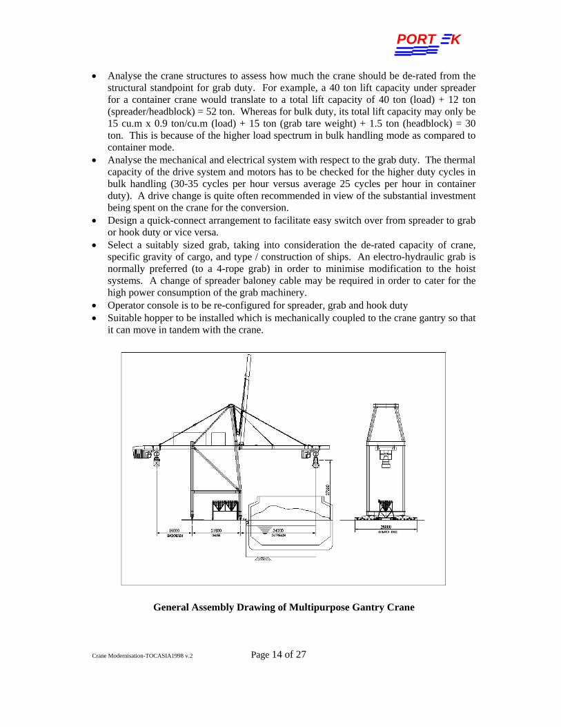
• Analyse the crane structures to assess how much the crane should be de-rated from the structural standpoint for grab duty. For example, a 40 ton lift capacity under spreader for a container crane would translate to a total lift capacity of 40 ton (load) + 12 ton (spreader/headblock) = 52 ton. Whereas for bulk duty, its total lift capacity may only be 15 cu.m x 0.9 ton/cu.m (load) + 15 ton (grab tare weight) + 1.5 ton (headblock) = 30 ton. This is because of the higher load spectrum in bulk handling mode as compared to container mode.
• Analyse the mechanical and electrical system with respect to the grab duty. The thermal capacity of the drive system and motors has to be checked for the higher duty cycles in bulk handling (30-35 cycles per hour versus average 25 cycles per hour in container duty). A drive change is quite often recommended in view of the substantial investment being spent on the crane for the conversion.
• Design a quick-connect arrangement to facilitate easy switch over from spreader to grab or hook duty or vice versa.
• Select a suitably sized grab, taking into consideration the de-rated capacity of crane, specific gravity of cargo, and type / construction of ships. An electro-hydraulic grab is normally preferred (to a 4-rope grab) in order to minimise modification to the hoist systems. A change of spreader baloney cable may be required in order to cater for the high power consumption of the grab machinery.
• Operator console is to be re-configured for spreader, grab and hook duty • Suitable hopper to be installed which is mechanically coupled to the crane gantry so that
it can move in tandem with the crane.
General Assembly Drawing of Multipurpose Gantry Crane

PORT K
Crane Modernisation-TOCASIA1998 v.2 Page 15 of 27
2.8 Budgetary Estimates (at 1998 prices) Price estimates of some major and minor upgrades
Modification Estimates (USD) Span Change 250k to 350k Height Change 500k Outreach Change 500k Elevator 100k Drum Brake to Disc Brake (Hoist) 20k Motor mounted Brake to Disc Brake (Gantry) 8 sets per crane
35k
Snag Load Protection 150k to 250k Centralised Lubrication – 5 sets per Crane 110k Spreader/Headblock Interchangeability 5k to 10k Conversion from container duty or multipurpose duty including drive change and hopper
1,100k

PORT K
Crane Modernisation-TOCASIA1998 v.2 Page 16 of 27
3.0 Modernization of Crane Electrical System Electrical system modernization or retrofit has been driven by the desire for improvement in reliability, productivity and safety, by the need to get away from obsolete systems no longer supported by manufacturers, and occasionally by crane relocation which may necessitate change of power supply and other upgrades. In this part of the paper, the following issues are discussed in relation to electrical system retrofit: • DC variable speed drive with Motor-Generator Ward Leonard (1900’s technology) • DC variable speed drive based on SCR converter (thyristor) with analog or hybrid
control technology (1960’s technology) • Digital DC drive and PLC (programmable logic controller) electronic components
which are more than 10 to 15 years old and face problems of poor parts availability and high maintenance cost.
• Recent emergence of AC inverter drives requiring less maintenance and smaller transformer or generator than DC drives.
• Need for higher crane speed leading to bigger motors and new drive system • Crane Management System (CMS) provides better diagnostics and reduces downtime • Advanced data communication technology allows Remote Crane Management System
(RCMS) for faster troubleshooting • Performance Improvement through automation to optimize the travel control and speed
pattern • New EC (European Community)safety standard for PLC and crane control system • Crane relocation from one port to another requiring modification to power supply
system • Wear and tear of operator cabin equipment leading to replacement with new and
ergonomically designed cabin and cabin equipment. 3.1 Drive System Retrofitting A typical drive system retrofitting comprises AC source modification, new hoist/gantry, trolley/boom drive panels, new master PLC controller, remote input and output modules for logic control, drive coordination and interfacing with external peripherals. Depending on the condition of the equipment, it may or may not be necessary to replace the DC motors and auxiliary components such as power distribution and motor control center panels, lighting, air-conditioning, warning systems, limit switches, operator chair and consoles, etc. A point to note with regards to the strong ultra-violet radiation encountered in the desert condition is that no wiring should be exposed, but should be shielded from the sunlight either in a conduit or concealed in one way or another. For that matter, any rubber or plastic materials tend to degrade rather rapidly when exposed to the strong sunlight.

PORT K
Crane Modernisation-TOCASIA1998 v.2 Page 17 of 27
3.1.1 Converting Ward Leonard Motor-Generator Set To DC SCR Drive Older generation cranes utilize variable speed DC drive motor excited by DC generator connected in the classical Ward Leonard configuration for container/cargo handling. From 1960’s to early 1980’s which saw the introduction of solid state SCR generator field exciter, the basic Ward Leonard configuration and performance criteria had changed very little. DC Drive System: The state-of-the-art DC drive system today is an integrated digitally based variable speed drive with other digital equipment including programmable logic controller, remote input and output modules, and personal computer via Local Area Network (LAN). The DC generators and its driving AC induction motor are no longer needed for the DC SCR armature supply drive. DC Motor: In many cases of crane drive retrofit, the existing DC drive motors (hoist, trolley, gantry and boom) can be given an overhaul and reused in the system to minimize the cost. Drive Isolation Transformer: A new drive isolation transformer is needed for most of the shore-powered cranes and for some of the diesel-generator powered cranes. This is so in order to build up an AC source for meeting the voltage requirement of the existing motors and the new DC drives. The advantages of installing the isolation transformer, even in cases where they are not strictly needed, includes: • Isolation of the drive from destructive and hazardous line-to-ground overvoltages
especially in some shore-powered systems; • The extra line impedance of the transformer reduces fault current levels. Hence,
reduced flash hazard and less drive damage from various fault conditions; • AC line disturbance is reduced by use of the transformer, improving the odds against
trouble with other equipment from line notching and harmonics caused by the SCR drives;
• Provision of a high resistance neutral grounding of the secondary of the transformer improves continuity of operation owing to higher tolerance of the drive system against the first ground fault, hence preventing shut down of the drive.
Control Voltage Transformer: A new control voltage bus formed by installing a ferroresonant power conditioner with filtered outputs and surge protection, provides a constant voltage to protect all downstream critical electronic equipment, such as PLC and I/O devices. The control voltage transformer can tolerate 15 to 20% voltage dips and maintain the output voltage within 5% of the nominal voltage. This is an extremely important feature in diesel-powered cranes and in some shore-powered crane.

PORT K
Crane Modernisation-TOCASIA1998 v.2 Page 18 of 27
3.1.2 DC Drive or AC Drive DC drive is a natural choice for most of the drive system retrofit because quite often, the existing DC motors can simply be overhauled and reused. The rapid growth of AC inverter drive in container cranes is mainly driven by expected lower maintenance cost of the AC motors, possible obsolescence of DC drive and the fast improving AC drive technology pushing it to the high KW range. When comparing the total cost of AC and DC drive systems including motors, the price difference is fairly small for micro, low-end to midrange drives (up to 200KW). However, the gap widens considerably in favor of DC system (up to 800KW) especially for high-end quayside crane main hoist and boom hoist drives and motors. Although it is generally believed that for the high KW range, costs may turn in favour of AC inverter in future. Since leading drive manufacturers are now focusing on AC inverter drive technology, we believe that AC inverter drive is going to become a standard in near future. In addition to its obvious advantage of lower motor maintenance, AC drive system operates at higher power factor, and hence reduces the total KVA demand, thus allowing the use of smaller transformer or smaller generator for diesel-powered crane. In addition, less harmonics are transmitted. On the other hand, current AC inverter drive/motor system suffers the disadvantage in that it develops torque slower than DC system owing to the sharing of drive between two different motions on a “First-Come, First-Served” basis. For example, hoist and gantry motions normally share one single drive unit such that starting the hoist motion from “zero” joystick position, a time lag of 1 to 3 seconds may be experience. However, depending on the users’ operation, these time lags may not be that significant In deciding to go for one or the other system (AC or DC) for drive retrofit, one should consider the economic cost versus the technical benefit trade-off. 3.1.3 Crane Control System Architecture When considering a crane drive retrofit, be it replacing an old Ward Leonard Motor Generator system or a DC SCR drive (analog or digital), it is important to give due consideration to the system architecture so that a well planned and truly integrated control system is achieved to facilitate accuracy, reliability, serviceability and to support future expansion. We have seen some crane control system suffering from a lack of centralized control, cluttered by many different proprietary communication protocols and interfaces, thus giving rise to slow response in signal processing of crane control functions. The newly retrofitted control system must adapt open system architecture with industry standard networking. The architecture must be simplified, the control centralized, and communication interfaces minimized. The DC or AC drives controller, crane master controller PLC and remote I/O should communicate on a common LAN to optimize system response times. This centralized approach allows all crane control application software to reside in the master controller PLC so that the status of all I/O and other crane peripheral

PORT K
Crane Modernisation-TOCASIA1998 v.2 Page 19 of 27
devices can be monitored by the master controller PLC. With an additional Ethernet network, the CMS and the remote CMS computer, or even other automation controller and sensor can be easily added on to the system. 3.1.4 A Case Study A new private terminal, Banten Port in West Java, has a 10 year-old disused container crane which is now required to be modified into a multipurpose crane capable of handling bulk, container and general cargo. Portek carried out a crane survey and found that the existing Ward Leonard control system was beyond repair due to some inherent system design defects and lack of maintenance. We considered and decided against the option of replacing the analogue excitation control sub-system with a new digital one supplied by the drive manufacturer. This is because there is no cost advantage in doing so. Furthermore, from our experience, any non-standard component, such as the digital field exciter, would be difficult in attracting technical support from the drive manufacturer. Portek was subsequently awarded the contract for the conversion to multipurpose duty and in addition to design, supply and install a new crane drive control system. Our objective is to provide a state-of-the-art fully digital DC SCR drive system but retaining the use of the existing Diesel-Alternator power supply, DC motors, auxiliary motor controls where possible. The DC generators were dismantled and discarded. The drive system architecture was completely reconfigured with the following major new components: • Drive Isolation Transformer and Control Power Transformer • Main Hoist / Gantry GE DV300 Drive Panel • Trolley / Boom GE DV300 Drive Panel • Master Controller GE Series 90-30 PLC Panel • Pumpback Control and Resistor Banks • Air-conditioned Electrical House • Cab/Spreader/Grab Panel • Operator Chair and Console The whole project including engineering, manufacturing, major mechanical repairs was completed in less than 5 months. In November 1998, the crane was successfully commissioned and sent for operation. Today the crane plays a critical role in the port operation. In this case, the drive system upgrade has given the crane a new lease of life and enable it to take on the more strenuous duty of bulk unloading.

PORT K
Crane Modernisation-TOCASIA1998 v.2 Page 20 of 27
Power Supply Configuration Before Retrofitting (Simplified)
Power Supply Configuration After Retrofitting (Simplified)

PORT K
Crane Modernisation-TOCASIA1998 v.2 Page 21 of 27
Control System Architecture
3.2 Modification of PLC System Product life cycles of electronic components are getting shorter and shorter. Although the physical life span of PLC products are much longer, their market life cycles are indeed rather short. Such market life cycles have gone from 10-15 years to 5-10 years and even to 3-5 years. This is due to the rapid rate of technological development and products get obsolete sooner than later. In general, these digital printed circuit boards are not repairable in case of card failure. A lot of crane users have been facing difficulty in obtaining these spare parts within 5 to 10 years from discontinuation of a product. The cost of replacing any printed circuit board becomes so high that it is often better to replace the entire PLC system with a new one. Secondly, older PLC systems have little capacity for expansion which may be needed as a result of modification to the crane. In addition, when crane user is considering increase of productivity by adding CMS or automation function, a new PLC system is essential for ensuring system compatibility and for achieving a centralized hardware platform. Further more, the modification of PLC system will invariably improve the safety standard of crane control system and the crane as a whole. New standards of safety have emerged for PLCs, such as the software development standard IEC1131-1. Replacing old PLC system will give user the chance to comply with this new standard by utilizing proven hardware and appropriate programming software. This would include features such as
PORT K
Crane Modernisation-TOCASIA1998 v.2 Page 22 of 27
hardwired safety circuits for emergency stops, structured software with function blocks and other safety controls to monitor the proper operation of the PLC. 3.3 Crane Management System (CMS) and Remote Crane Management System
(RCMS) As mentioned in section 3.1.3, open system architecture with centralized control and industry networking is an essential environment for connecting a CMS and RCMS computer. A CMS retrofit package with MS Windows 95 or NT platform can enhance crane diagnostics and enable faults to be rectified very quickly, thus minimizing crane downtime. Quite often, introduction of CMS may require change of PLC system as well. The function of a typical CMS includes: • Crane Condition Monitoring displaying the current operating status of the crane via
graphic and text object animation • Fault Diagnostics provides active alarm and historical alarm/event with help information • Operation Log generating crane production reports and charts • Preventive Maintenance allowing on-line configuration, monitoring, warning and
tracking of preventive maintenance activities • PLC programming tool By adding an Ethernet network either via Fiber Optic communication for cranes equipped with fiber optic composite cable or via RF Ethernet communication, Remote CMS can be realised such that crane data can be transmitted to and displayed in a remote maintenance or administration building. 3.4 Higher productivity through Speed Increase Crane cycle time particularly has a major impact on overall productivity of a quay side container crane. Increase of hoist and trolley speeds can be considered along with a crane drive/motor upgrade. However, such speed increase can only effected within the limits imposed by the mechanical and structural systems of the crane. Older cranes often do have some reserves in their design, which could tolerate acceleration and speed increase. Use of disc brakes (which have much lower polar moment of inertia than drum brakes) and newer / lighter spreaders may further allow the crane to accommodate small increase in hoist speed. In general, small speed change of up to 10% may be tolerated by the structural / mechanical systems. More meaningful speed change would be in the region of 20%, in which case the entire drive train (gear box, brakes, couplings and rope reeving) may have to be upgraded as well. 3.5 Performance Improvement by partial Automation If the crane already has an advance control system architecture with capacity for expansion, it is feasible to look into implementing partial automation to optimize load trajectory. This may be attempted in the case of quayside container crane or some bulk unloaders. For RTGs, the cost / benefits trade-off is certainly not in favour of any automation. On the other hand, rail mounted gantry cranes (RMGs) would quite readily lend themselves to semi- or
PORT K
Crane Modernisation-TOCASIA1998 v.2 Page 23 of 27
partial automation. 3.6 Modification of Power Supply System Many older cranes are still diesel powered. Such cranes are more costly to maintain, have lower availability, present a dirty environment to work in and are more prone to fires. Changing them to cable reel shore power supply is a very tempting proposition which many users will find hard not to consider if they have adequate shore power. Crane relocation is another situation which often requires a change of power supply either from cable reel shore power to diesel power or vice versa. Converting diesel power to cable reel shore power is an easier and more straightforward modification and generally costs less. While converting shore power to diesel power requires the provision of large regenerative power absorption resistor banks, diesel fuel storage and delivery system and controls, hence a more costly exercise. When installing a new cable reeling power supply system, it is advisable to adopt the composite power cable which incorporates fibre optics cores. A separate optical coupler residing in the collector box of the cable reel serves to connect the optical fibre between moving parts. 3.7 Cable reel for spreader cable Development in digital communication in the harsh spreader environment has now enabled all signals between the spreader and the crane to be transmitted via only two unshielded cores of a standard spreader cable. A small diameter spreader cable with 12 cores or less is now more than sufficient to transmit power and signals between the crane and spreader. A cable reel can be positioned in the trolley to keep the spreader cable tensioned at all times. This would be particularly advantageous in preventing cable getting damaged as when it falls out of cable basket owing to high wind or high trolley acceleration. 3.8 Improved Operator Cabin During the life of a container crane it should be expected that the operator cabin would be replaced in entirety due to wear and tear, deterioration from corrosion and complaints from operator for want of better comfort. To put it another way, the operator cabin wears out before the crane. Operator’s immediate working environment is an important contributor to operator efficiency and productivity. A modified operator cabin shall be designed with the best ergonomics so as to create a natural sitting condition, to enable an operator to look down at the load without losing comfort of sitting and leaning against back rest for lumbar support. Just try sitting in the crane cabin for a couple of hours, shuttling to and for at 210 m/min, and you will quickly appreciate the importance of a well-designed operator cabin. The operator console shall be ergonomically laid out and equipped with reliable joystick controller and other operator devices for the safe operation of crane. In most of the drive

PORT K
Crane Modernisation-TOCASIA1998 v.2 Page 24 of 27
system retrofitting project, the joystick controllers have to be compatible with the new digital drive control system for faster response. The operator chair should be capable of various angles of adjustment and should incorporate a V-cut in the seat to help reduce operator fatigue and improve visibility.
Ergonomically Designed Operator Chair
3.9 Budgetary Estimates (at 1998 prices) The table below shows estimated cost for various electrical systems retrofitting work scope including installation and commissioning: MODIFICATION CRANE TYPE ESTIMATES
(USD) Drive System Retrofit without motor QC 450k Drive System Retrofit without motor RTG 150k Drive System (AC or DC) Retrofit with new motor QC 600k Drive System (AC or DC) Retrofit with new motor RTG 300k PLC System Modification with CMS QC 80k PLC System Modification with CMS RTG 70k Conversion from diesel power to cable reel shore power QC 90k Conversion from shore power to diesel power QC 280k Improved Operator Cabin QC 60k
Price premium may be added depending on location and other factors.
PORT K
Crane Modernisation-TOCASIA1998 v.2 Page 25 of 27
4.0 General Comments 4.1 Not Forgetting “Time Is Of the Essence” In any crane modernization exercise, due consideration has to be given to the length of time during which the crane will have to be shut down and immobilized on the quay. Shutting down the crane could pose some inconvenience and possible disruption to the usual flow of traffic on the quay. However, it is possible to keep the crane shut down time to the minimum with careful planning and scheduling, proper job execution and working longer hours each day. Selection of experienced and competent contractors who are able to perform under strict time limits is key to a successful crane upgrade. Most of the major upgrades described above (whether mechanical, structural or electrical work) would require at most 4 to 5 weeks of crane shut down for the actual on-site work. The total contract period for an upgrade will of course be longer owing to time required for engineering, equipment procurement, etc. A drive retrofit contract would be in the region of 5 to 7 months whereas a structural upgrade contract would be in the region of 3 to 4 months. 4.2 Procurement Procedures Having decided on a major crane upgrade, there are several commonly practiced procedures by which an owner can go about awarding the job to the right party. 4.2.1 Turnkey Design and Build Contract The owner pre-qualifies several experienced and competent contractors with known design and contracting capabilities. After consultation with such contractors prior to issuing formal inquiry, the owner would have developed a good idea of what is technically feasible and economically viable, and he then goes on to finalise the performance specification. Through a process of private negotiation or formal bidding, proposals are evaluated and contracts awarded accordingly. The advantage with this method is that there is only a single party to deal with. The contractor assumes total responsibility including design and project responsibility. Attractive prices could often be obtained. This method would work well especially if contractors are reputable and have a known track record for such work, and are personally known to the owners such that any unclear areas in the contract could be settled through compromise in a spirit of give and take. 4.2.2 Appoint separate Consultant and Contractor Where there is no competent contractor available, the owner could appoint a Consultant specialised in this field of work to draw up detailed specification. Such specification could state clearly “the ends and the means” of the upgrading exercise, giving details of the final performance criteria as well as the method of achieving those criteria. In this case the Consultant bears the design responsibility, while the contractor just have to carry out the work scope drawn up by the Consultant. The expertise resides largely with the Consultant.

PORT K
Crane Modernisation-TOCASIA1998 v.2 Page 26 of 27
The advantage of this arrangement is that the Consultant will compensate for the owner’s lack of knowledge in this field and relieve the owner of the many tasks associated with seeing the project through. The disadvantage is that total costs may be higher since the owner has to pay both the Consultant and Contractor. In addition, it may difficult to find suitable Consultant with competence in this area. 4.2.3 Appoint Original Crane Manufacturer While this has the advantage that the original crane manufacturer may have all necessary data which will put them in a good position to carry out structural modification work, many crane manufacturers are not used to nor are they equipped to carry out extensive on-site work. They lack the motivation to pursue relatively small jobs like this, and consequently they may not be competitive in their quotation. In any case, most old cranes are long out of their warranty period, and are no longer supported by the crane manufacturers in terms of spare parts and technical back up. So crane owners really should not have any reservation in going to any third party contractors.

PORT K
Crane Modernisation-TOCASIA1998 v.2 Page 27 of 27
5.0 CONCLUSION - Can your old crane rise to the occasion? In the foregoing, we have dealt with the technical as well as the commercial aspects of crane upgrade and retrofit. Whether or not to go for a crane upgrade is essentially a business decision. For an owner to decide in favour of crane upgrade, he must be convinced that the resulting benefits would outweigh the costs, or in other words, he must get his payback within a reasonable period of time say 3 to 5 years. This is in fact very probable if one can cite the findings in a paper entitled “Crane Prices – Boom, Bust or Bonanza” presented in TOC 98 Antwerp in which was mentioned that a one percent improvement in crane availability would result in revenue gain of USD 219,000 per crane per year. Advances in the medical science has not only prolonged man’s life, but also greatly improved his quality of life. Performance enhancing drugs such as the Viagra has shown us that manhood can be restored and life can still be enjoyable despite the onset of age. Similarly, there is nothing like having a boom job and a drive change to give your old crane a new lease of life so that it will rise to the occasion every time. One no longer needs to lament about “The spirit is willing, but the flesh is weak”!! For further information regarding the contact of this article, please contact: Portek International Limited Portek Systems & Equipment Pte Ltd 20 Harbour Drive, #02-01, PSA Vista, Singapore 117612 Tel: (65) 68731114 Fax: (65) 68732224 Email: [email protected] Internet address: http://www.portek.com


![OPTIMIZATION AND FATIGUE ANALYSISOF A CRANE HOOK …fatigue life contour plots of crane hook using Ansys Workbench and Ansys nCode DesignLife. ... A Gopichand. Et al. [16] studied](https://static.fdocuments.us/doc/165x107/5e2a3a1363a9812dd90d6d8e/optimization-and-fatigue-analysisof-a-crane-hook-fatigue-life-contour-plots-of-crane.jpg)