Crane Fly Lite - Model Flying, the online home of RCM&E ... 6mm x 6mm x 200mm Triangular Section...
25
Crane Fly Lite Crane Fly Lite A Tom Wright Design Rev 1.1a 1 Crane Fly Lite A Tom Wright Design
Transcript of Crane Fly Lite - Model Flying, the online home of RCM&E ... 6mm x 6mm x 200mm Triangular Section...

Crane Fly Lite
Crane Fly Lite A Tom Wright Design Rev 1.1a
1
Crane Fly Lite
A Tom Wright Design

Crane Fly Lite
Crane Fly Lite A Tom Wright Design Rev 1.1a
2
Contents
Introduction ................................................................................................................................................... 3
Acknowledgements ....................................................................................................................................... 3
Parts List ........................................................................................................................................................ 4
Specification .................................................................................................................................................. 5
Fuselage Construction ................................................................................................................................... 6
Tail Support ................................................................................................................................................... 7
Rudder Control Arm ...................................................................................................................................... 8
Rudder ........................................................................................................................................................... 8
Fin .................................................................................................................................................................. 8
Tail-Plane ...................................................................................................................................................... 9
Elevator ......................................................................................................................................................... 9
Mast Top ...................................................................................................................................................... 10
Fitting the Mast............................................................................................................................................ 10
Roll Control Arm ......................................................................................................................................... 11
Variant 1 .................................................................................................................................................. 11
Variant 2 .................................................................................................................................................. 12
Delta Plate ................................................................................................................................................... 13
Undercarriage .............................................................................................................................................. 14
Tailskid ........................................................................................................................................................ 14
Servo Mounting ........................................................................................................................................... 15
Rudder and Elevator Servo ...................................................................................................................... 15
Roll Control Installation and Servo ......................................................................................................... 15
Rotor Blade Construction ............................................................................................................................ 16
Blade Root Re-enforcement .................................................................................................................... 17
Blade Balancing ........................................................................................................................................... 18
Blade Covering ............................................................................................................................................ 18
Rotor Blade Installation ............................................................................................................................... 18
Initial Setup ................................................................................................................................................. 19
Trimming and pre-maiden checks ............................................................................................................... 19
First Flight ................................................................................................................................................... 20
Drawings...................................................................................................................................................... 22
Balsa Parts (6mm) ................................................................................................................................... 22
Balsa Parts (3mm) ................................................................................................................................... 23
Glass Fibre Parts ...................................................................................................................................... 24
Piano Wire Parts ...................................................................................................................................... 25

Crane Fly Lite Introduction
Crane Fly Lite A Tom Wright Design Rev 1.1a
3
Introduction
Thank you for taking time to download the Crane Fly Lite Autogyro build details, but be warned this
fascinating offshoot of our hobby can be very addictive and often challenging, as applying certain aspects of
fixed wing intuition may sometimes not produce the desired results. Over the years many have dabbled and
given up on Autogyros because the machines were too demanding to fly without experiencing frequent
mishaps resulting in long repair sessions, and uncertainty about what went wrong.
The Crane Fly Lite is designed specifically to maximise the chances of early and on-going success, if the
model is built to plan, flown, and trimmed in accordance with the suggestions within this document. A single
rotor Autogyro will probably never be a suitable project for a novice pilot but this design endeavours to
make success feasible for “A” standard pilots onwards, and is equally suitable for very experienced pilots
wishing to get started with what is often referred to as the “dark art”.
The Crane Fly Lite is an attempt to lift the dark veil and is the result of many hundreds of hours work in
collaboration with experts in various associated fields who have given their time and energy freely to enable
me to complete the project and make it available to all model enthusiasts.
The design is subject to copyright so any recipient intending to use it for commercial gain must contact me in
writing beforehand.
Constructors are asked to kindly post on the modelflying.co.uk or rcgroups.com autogyro forums, whenever
possible, photos, videos, or text as the build progresses, and of course the outcome in terms of flight success.
But most importantly do ask questions particularly if you are new to Autogyros.
Good Rotations.
Tom.
Acknowledgements
The Crane Fly Lite concept was developed after many hours flying conventionally configured Autogyros and
during this time taking note of the control characteristics that presented the greatest challenge to pilots flying
single rotor machines for the first time.
During the development process other enthusiasts, some with professional qualifications in related
disciplines, took interest and began to provide input to the project, so it would be remiss of me not to extend
a thanks in recognition of the many hours work freely given to enable the project to become available to all
wanting to get started with an Autogyro project for the first time, or indeed for RC pilots who may have not
succeeded first time around.
My thanks and appreciation goes to:
Giovanna My Partner
Malcolm Hancock For applying his Technical drawing and three dimensional CAD skills;
mechanical engineering advice and test flying the clone prototype.
“Mickey” Nowell For help and advice, in respect to aerodynamics and rotary physics.
Dave Mellor For volunteering as a novice pilot flight assessor and providing great
encouragement throughout the project.
All the RCM&E forum guys who have provided feedback from PDF previews.
The Lads at the field Including Pete, Fred, Stuart, Richard, Mark, Richard and Peter for input after
flying the model.
Stuart Eggerton HD video and flight assessments.
And last but not least;
Rich Harris For originally inspiring my interest in Autogyros.

Crane Fly Lite Parts List
Crane Fly Lite A Tom Wright Design Rev 1.1a
4
Parts List
Part Description Quantity Used on Web
Link
Balsa 3mm x 75mm x 900mm 1 Med Sheet All Tail/Fin Parts
Balsa 6mm x 75mm x 900mm 1 Soft Sheet Fuselage Cabin
Balsa 5mm x 75mm x 900mm 1 Hard Sheet Rotor blades
Balsa 5mm x 19mm x 900mm 2 Trailing
Edge
Rotor blades
Balsa 6mm x 6mm x 200mm Triangular
Section
Tail/Fin Support
Spruce 6.5mm x 12.5mm x
920mm
1 Strip Boom/Mast/Roll
Control Arm
G10/FR4 Glass Fibre
Sheet
0.4mm (1/64") 300mm x
150mm
Various Coolwind
G10/FR4 Glass Fibre
Sheet
0.8mm (1/32") 110mm x
110mm
Delta Plate Coolwind
CNC cut GF Parts and
Delta plate
All GF Parts +
Delta Plate
Coolwind
Servo 3.7g mini man 2 Elevator/Rudder Giant
Shark
Servo Tower Pro MG90 1 Roll Control Giant
Shark
Motor Emax BL1812 (1800kV
140W)
1 Giant
Shark
Prop DD7040 GWS Style EP
Prop 7x4
1 Giant
Shark
ESC 20A or higher with BEC 1 Giant
Shark
2mm Gold Connector
pairs
3 pairs Motor/ESC
Connection
LiPo Battery 1000mAh 3S 20C 1 Giant
Shark
Receiver 3 or more
Channels
1
Blue Wonder Motor
Mount
1 Rotor Bearing
Holder
Giant
Shark
Flange Bearing 3x8x4 - (F693zz) 2 Rotor Bearing Coolwind
Servo Extension Lead 500mm Ultra Light Type 2 min length 350mm Giant
Shark
Y-Lead 100mm 1 short as possible Giant
Shark
Piano Wire 18 SWG - (1.2mm) 3 lengths Blades, Rudder Arm, Tail Skid,
Elevator/Rudder
Piano Wire 12 SWG - (2.5mm) 1 length Undercarriage
Push Rod 2mm 85mm long Roll control
Crane Fly Lite Parts List
Crane Fly Lite A Tom Wright Design Rev 1.1a
5
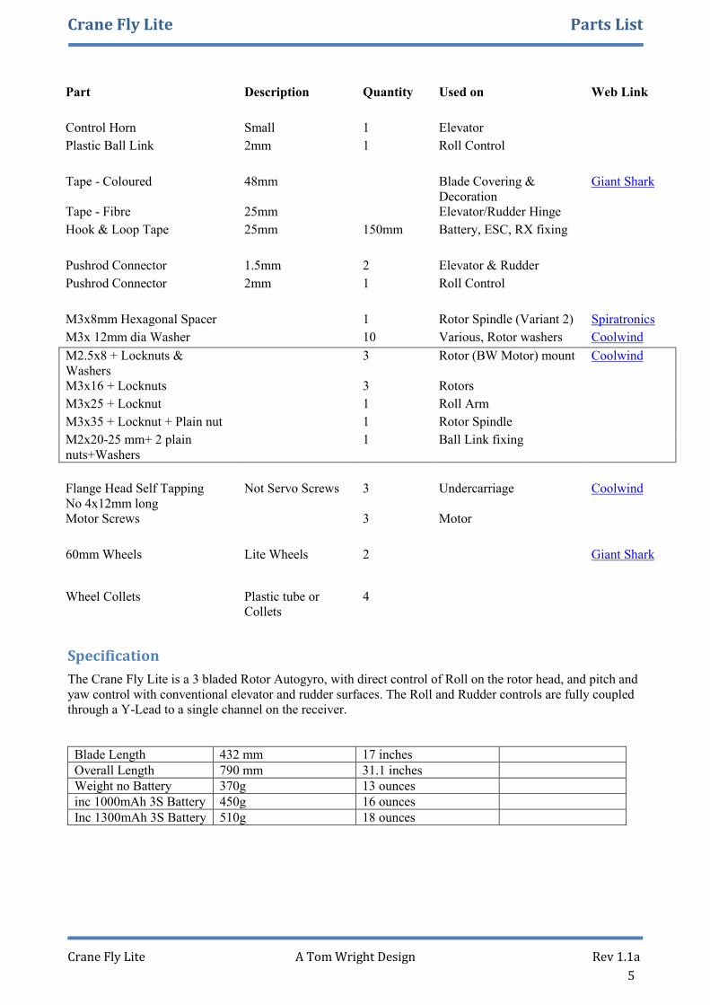
Part Description Quantity Used on Web Link
Control Horn Small 1 Elevator
Plastic Ball Link 2mm 1 Roll Control
Tape - Coloured 48mm Blade Covering &
Decoration
Giant Shark
Tape - Fibre 25mm Elevator/Rudder Hinge
Hook & Loop Tape 25mm 150mm Battery, ESC, RX fixing
Pushrod Connector 1.5mm 2 Elevator & Rudder
Pushrod Connector 2mm 1 Roll Control
M3x8mm Hexagonal Spacer 1 Rotor Spindle (Variant 2) Spiratronics
M3x 12mm dia Washer 10 Various, Rotor washers Coolwind
M2.5x8 + Locknuts &
Washers
3 Rotor (BW Motor) mount Coolwind
M3x16 + Locknuts 3 Rotors
M3x25 + Locknut 1 Roll Arm
M3x35 + Locknut + Plain nut 1 Rotor Spindle
M2x20-25 mm+ 2 plain
nuts+Washers
1 Ball Link fixing
Flange Head Self Tapping
No 4x12mm long
Not Servo Screws 3 Undercarriage Coolwind
Motor Screws 3 Motor
60mm Wheels Lite Wheels 2 Giant Shark
Wheel Collets Plastic tube or
Collets
4
Specification
The Crane Fly Lite is a 3 bladed Rotor Autogyro, with direct control of Roll on the rotor head, and pitch and
yaw control with conventional elevator and rudder surfaces. The Roll and Rudder controls are fully coupled
through a Y-Lead to a single channel on the receiver.
Blade Length 432 mm 17 inches
Overall Length 790 mm 31.1 inches
Weight no Battery 370g 13 ounces
inc 1000mAh 3S Battery 450g 16 ounces
Inc 1300mAh 3S Battery 510g 18 ounces

Crane Fly Lite Fuselage Construction
Crane Fly Lite A Tom Wright Design Rev 1.1a
6
Fuselage Construction
The Crane Fly Lite Fuselage is constructed from 6mm balsa sheet mounted on a Spruce boom and re-
enforced with Glass fibre sheet for the Motor mount, undercarriage mount and tail-plane assembly.
The boom is made from a single piece of 6.5 x 12.5mm Spruce strip, 700mm
long.
Prepare the Spruce strip by drilling a 1.5mm hole in the narrow face at an angle
of 45 degrees and 10mm in from the end in readiness for fitting the tail-skid at a
later stage of construction.
The fuselage floor is made from 6mm balsa 330mm x 50mm with the last 50mm
of the floor tapered down to the boom width.
Glue the Spruce Boom onto the balsa fuselage floor ensuring that the tail-skid
hole is at the back and on the bottom and that the spruce boom is centred on the
balsa floor.
Cut and prepare the 6mm fuselage sides and formers as detailed in the drawings.
Test fit the fuselage parts to the
floor/boom assembly. The fuselage sides
have built-in motor down-thrust and mast
tilt angles of 5 degrees, so it will be
necessary to trim the bottom of the
firewall, bottom of the rear former and
the inside of the boom slots to ensure
they sit at the required 5 degree angle.
When satisfied with the fit, cyno the
fuselage parts in place
Trim the front edge of the fuselage floor so it is flush
with the firewall.
Pre-drill the holes in the fibreglass firewall to fit your
chosen motor, with the motor centre at 18mm from the
top edge.
The motor mounting holes should be sized to match the
self-tapping screws which will attached the motor
A 5mm clearance hole for the motor shaft, and a similar
sized hole for the motor wiring are also required.
Glue the fibreglass firewall in place.

Crane Fly Lite Fuselage Construction
Crane Fly Lite A Tom Wright Design Rev 1.1a
7
On the underside of the fuselage
add the Undercarriage Mount,
Cable exit plate and a 25mm wide
piece of Velcro for holding the
battery in place.
Note that the holes in the
undercarriage mount are pilot
holes for the self-tapping
undercarriage screws.
Cut away the balsa inside the
cable exit plate
On the inside of the fuselage add two small GF re-
enforcement plates for the front two undercarrirage
screws to bite into, strengthening the undercarriage
mounting.
Tail Support
Finally add the 40 x 50mm GF tail plane support plate and its two supporting 50mm long balsa 6mm triangle
section pieces. Glue these securely in place.
The Fuselage assembly can now be put to one side whilst the tail-plane components are constructed

Crane Fly Lite Tail Construction
Crane Fly Lite A Tom Wright Design Rev 1.1a
8
Rudder Control Arm
The Rudder control arm is constructed from a 90mm
length of 1.2mm diameter piano wire. The two
angled sections each being 20mm long and the
centre section is 50mm long.
The wire can easily be bent by using pliers.
Ensure the bent arms are at 90 degrees to each other
On the lower 20mm section glue the three glass fibre
parts and attach a small (1.5mm) control rod clamp.
Rudder
The Rudder is constructed from medium hardness 3mm balsa, 124x32mm with a decorative rounded top
corner and an angled cut-off at the base to allow for elevator movement.
The rudder is hinged with a tape hinge on its left-
hand side. The edge of the rudder which will
mate with the fin needs to be sanded to a 35
degree angle to allow Rudder movement.
On the right-hand side of the Rudder at the bottom, carve a slot to
accept the previously bent control arm. The horizontal section of
the cut out should be 23mm from the lowest edge of the Rudder.
Cyno the control arm in place and then re-enforce the side with a
glass fibre plate.
Fin
The fin is constructed from a single piece of medium hardness 3mm balsa,
132x69mm, with a leading edge slope designed to minimize the chances of blade
strikes during heavy arrivals.
Shape the Fin as shown on the template/drawing page and attach the Rudder to it
using a piece of 25mm wide fibre tape as a hinge.
Crane Fly Lite Tail Construction
Crane Fly Lite A Tom Wright Design Rev 1.1a
9
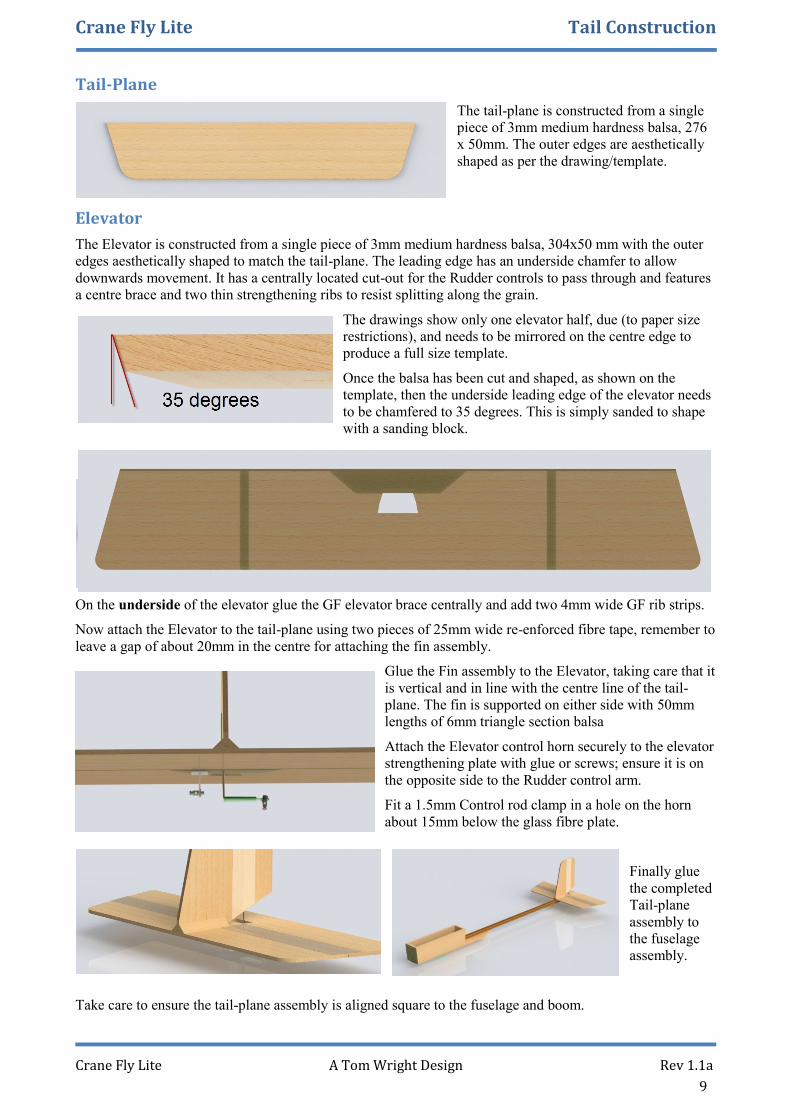
Tail-Plane
The tail-plane is constructed from a single
piece of 3mm medium hardness balsa, 276
x 50mm. The outer edges are aesthetically
shaped as per the drawing/template.
Elevator
The Elevator is constructed from a single piece of 3mm medium hardness balsa, 304x50 mm with the outer
edges aesthetically shaped to match the tail-plane. The leading edge has an underside chamfer to allow
downwards movement. It has a centrally located cut-out for the Rudder controls to pass through and features
a centre brace and two thin strengthening ribs to resist splitting along the grain.
The drawings show only one elevator half, due (to paper size
restrictions), and needs to be mirrored on the centre edge to
produce a full size template.
Once the balsa has been cut and shaped, as shown on the
template, then the underside leading edge of the elevator needs
to be chamfered to 35 degrees. This is simply sanded to shape
with a sanding block.
On the underside of the elevator glue the GF elevator brace centrally and add two 4mm wide GF rib strips.
Now attach the Elevator to the tail-plane using two pieces of 25mm wide re-enforced fibre tape, remember to
leave a gap of about 20mm in the centre for attaching the fin assembly.
Glue the Fin assembly to the Elevator, taking care that it
is vertical and in line with the centre line of the tail-
plane. The fin is supported on either side with 50mm
lengths of 6mm triangle section balsa
Attach the Elevator control horn securely to the elevator
strengthening plate with glue or screws; ensure it is on
the opposite side to the Rudder control arm.
Fit a 1.5mm Control rod clamp in a hole on the horn
about 15mm below the glass fibre plate.
Finally glue
the completed
Tail-plane
assembly to
the fuselage
assembly.
Take care to ensure the tail-plane assembly is aligned square to the fuselage and boom.

Crane Fly Lite Mast and Rotor Control Arm Construction
Crane Fly Lite A Tom Wright Design Rev 1.1a
10
Mast Top
The mast is constructed from a straight length of 6.5 x 12.5mm spruce - 148mm in length.
The first task is to clad the top of the mast in GF sheeting.
Use the mast as a gude to mark out the width of the GF parts.
These are then cut with scissors and glued in place with cyno
Three sides at the top of the mast need to be clad in GF
as shown in the picture
Then a 3mm hole is drilled 6mm from the top in the
centre of the narrow face.
Care needs to be taken to ensure that the hole is drilled
square to the mast as this forms the pivot point for the
Autogyro’s roll control. The use of a pillar drill is
highly recommended for this task.
Fitting the Mast
The mast is required to tilt 5 degrees backwards when fitted to the model. This angle is built-into the
fuselage box construction, however, the base of the mast needs to be trimmed so that it sits neatly on the
boom.
Shape the bottom of the mast
by removing 1mm from the
back edge. This will create
the required 5 degree angle.
The completed Mast can then
be glued to the rear former
and boom and then re-
enforced with the two
fibreglass plates shown on
the drawings/template pages.
These also have the 5 degree
angle built-in to them.
Glue the Servo mounting
plate to the mast 55mm from
the top.

Crane Fly Lite Mast and Rotor Control Arm Construction
Crane Fly Lite A Tom Wright Design Rev 1.1a
11
Roll Control Arm
The Rotor Control Arm is offered in two different variants, both are functionally identical but offer the
builder a choice of construction methods dependant on the parts or tools they have available.
The Control arm is mounted on the mast with an M3x25mm screw with large washers on both sides and an
M3 locknut.
Variant 1
This variant uses an M3x30mm socket head cap screw as the rotor pivot.
An M3 die may be required to extend the threaded section by 2mm.
Construction
The Rotor control arm is constructed from a 50mm length of 6.5x12.5 spruce.
First drill the fixing hole for a 2mm ball link connector. This is a 2mm hole in the
narrow face of the spruce, located 5mm in from the end.
Clad the opposite end of the spruce in GF sheet in a similar fashion to
the mast top. Ensure you use the same thickness GF as on the mast.
Four pieces of GF are required; two 12.5mm square and two 6.5mm x
25mm. These are easily cut-out with scissors
Now drill a 3mm hole through the control arm at the centre of the
12.5mm square GF cladding. Again this needs to be square, so use a
pillar drill to ensure accuracy.
Finally cut and glue the side plates over the clad control arm. The two
holes in the side plates need to be aligned accurately. This can be
achieved by temporarily bolting them to the mast top with an M3
screw whilst the glue on the control arm sets.
The rotor bolt (M3x30mm) is inserted from the underside of the arm.
Note that unthreaded shank of the bolt will protrude through the top
surface of the control arm.
M3x12mm washers are used as packing to cover the unthreaded shank
and allow a plain nut to tighten down on the control arm face, locking
the rotor bolt in place.
The exposed threaded shaft needs to be long enough to fully accept
the Rotor bearing, its housing and a locknut (see assembly in next
section). If this is not the case, due to tolerances on your parts, then
the threaded section of the screw will need to be extended to allow
satisfactory assembly. An M3 die will be required to do this. If you
have used a hardened M3 screw then the dies generally available on
the hobby market may not be strong enough to cut the extra thread and variant 2 of the design should be
considered.

Crane Fly Lite Mast and Rotor Control Arm Construction
Crane Fly Lite A Tom Wright Design Rev 1.1a
12
Variant 2
This variant uses an M3x30mm socket head cap screw which screws into an M3x8mm
hexagonal spacer glued into the spruce arm. The rotor bearings run on the unthreaded
part of the screw.
Construction
The Rotor control arm is constructed from a 50mm length of 6.5x12.5 spruce.
First drill the fixing hole for a 2mm ball link connector. This is a 2mm hole in the
narrow face of the spruce, located 5mm in from the end.
Then drill a 5.5mm hole for the hexagonal spacer.
The spacer should be a tight fit in the hole, generally 5.5mm
is fine for the metric spacers; for other types measure the
maximum distance across the spacer and use the next
smaller drill size. The length of the spacer is not critical, but
it should not protrude greater than 3mm from the underside
of the control rod, to allow adequate clearance from the
mast when assembled.
Tap the spacer through the hole, apply some medium cyno and tap it back in the hole until the top of the
spacer is level with the top of the control arm.
Now drill a 3mm hole in a 12.5mm square piece of GF and glue it
over the top of spacer to provide additional resistance to pull
through of the spacer under load.
Next add a similar size GF piece on the underside with a hole in it
to clear the protruding spacer.
Add the two side GF spacer plates, and the two GF Control arm
pivot side plates. The two holes in the side plates need to be
aligned accurately. This can be achieved by temporarily bolting
them to the mast top with an M3 screw whilst the glue on the
control arm sets.
The completed control arm assembly
Crane Fly Lite Delta Plate Construction
Crane Fly Lite A Tom Wright Design Rev 1.1a
13
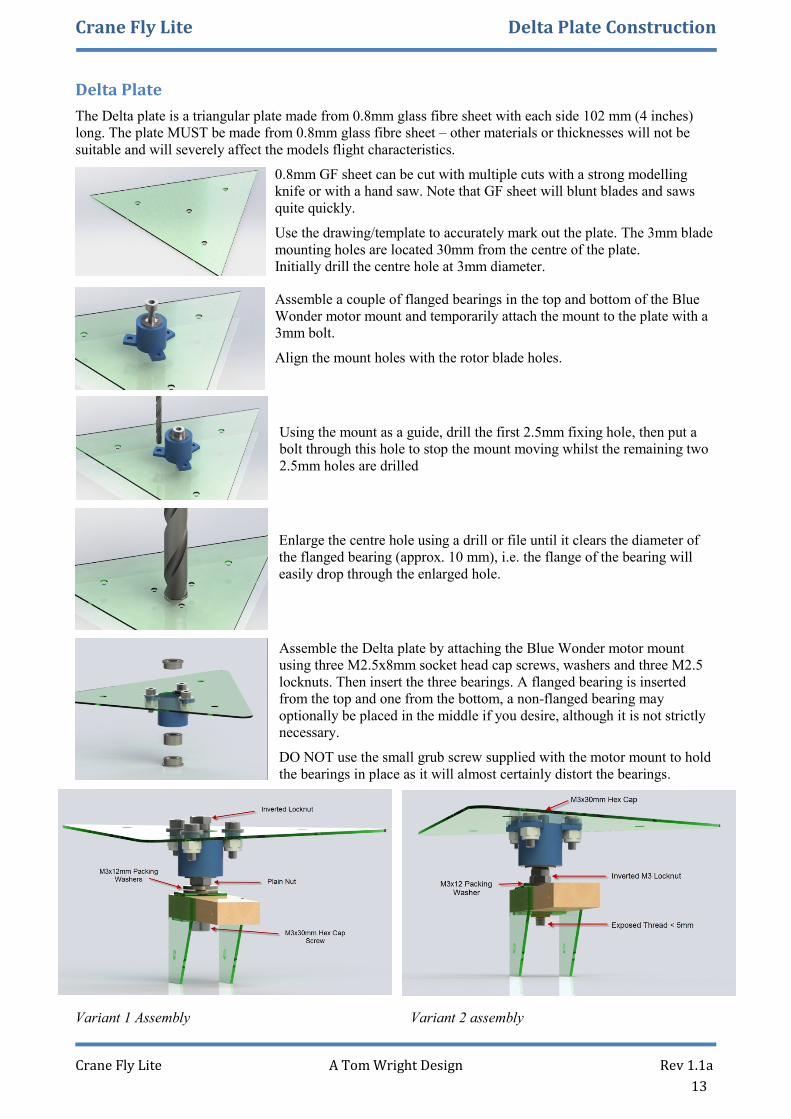
Delta Plate
The Delta plate is a triangular plate made from 0.8mm glass fibre sheet with each side 102 mm (4 inches)
long. The plate MUST be made from 0.8mm glass fibre sheet – other materials or thicknesses will not be
suitable and will severely affect the models flight characteristics.
0.8mm GF sheet can be cut with multiple cuts with a strong modelling
knife or with a hand saw. Note that GF sheet will blunt blades and saws
quite quickly.
Use the drawing/template to accurately mark out the plate. The 3mm blade
mounting holes are located 30mm from the centre of the plate.
Initially drill the centre hole at 3mm diameter.
Assemble a couple of flanged bearings in the top and bottom of the Blue
Wonder motor mount and temporarily attach the mount to the plate with a
3mm bolt.
Align the mount holes with the rotor blade holes.
Using the mount as a guide, drill the first 2.5mm fixing hole, then put a
bolt through this hole to stop the mount moving whilst the remaining two
2.5mm holes are drilled
Enlarge the centre hole using a drill or file until it clears the diameter of
the flanged bearing (approx. 10 mm), i.e. the flange of the bearing will
easily drop through the enlarged hole.
Assemble the Delta plate by attaching the Blue Wonder motor mount
using three M2.5x8mm socket head cap screws, washers and three M2.5
locknuts. Then insert the three bearings. A flanged bearing is inserted
from the top and one from the bottom, a non-flanged bearing may
optionally be placed in the middle if you desire, although it is not strictly
necessary.
DO NOT use the small grub screw supplied with the motor mount to hold
the bearings in place as it will almost certainly distort the bearings.
Variant 1 Assembly Variant 2 assembly

Crane Fly Lite Undercarriage Construction
Crane Fly Lite A Tom Wright Design Rev 1.1a
14
Undercarriage
The undercarriage is constructed from a 480mm length of 2.5mm diameter (12SWG) piano wire which is
bent to shape using a hammer and vice. It is attached to the model on the undercarriage mount by three
Flange headed steel self-tapping screws. No 4x12mm. The undercarriage is held in place by its built-in
spring tension against the three screws.
The undercarriage is designed to take reasonable impact during a landing and to spring off in the event of a
heavy arrival. It is not designed for ROG as the model is normally hand launched.
Construction
Take the 480mm length of piano wire and make a tight bend at the
centre to form a Vee shape. You are aiming for an angle of around 30
degrees.
Then place the Vee into a vice, holding about 40mm in the vice. Bend
the protruding legs forward and outward with a hammer or other tools,
until the forward rake of the legs is around 15-20 degrees and the gait
is around 300mm. These are not critical dimensions, but the
undercarriage needs to be wide to prevent tip-over when the model
lands.
Finally bend the ends outwards to form the two axles about 20mm
long. These should be in-line with each other. Final adjustments to the
stance of the undercarriage should then be made until it is similar to
the drawings provided.
Add the Wheels, secured with wheel collets or short sections of plastic
tube held in place with cyno.
The undercarriage is attached to the model using No4 A2 Stainless steel
flanged self-tapping Screws.
Please note that these are NOT servo screws, which are very soft and
unsuitable. If sourcing them, or an equivalent, proves difficult then M3
screws with a washer and nut may be substituted.
Tailskid
The tailskid is made from a short length of 1.2mm piano
wire.
Using a pair of pliers, make a small loop at one end of the
wire, then glue the Tailskid into the hole at the rear of the
boom.

Crane Fly Lite Servo Mounting
Crane Fly Lite A Tom Wright Design Rev 1.1a
15
Servo Mounting
All the servos on the model are fixed to the model using medium cyno.
Firstly, remove any labels from the servo side faces where cyno will be used. Roughen up the plastic surface
with abrasive paper, apply a small amount of medium cyno and hold the servo in place until the cyno cures.
Curing will take longer than the time the manufacturer states for the curing time as there is little or no
moisture in the faces being mated to kick off the curing process. Be patient.
Rudder and Elevator Servo
The Rudder and elevator are controlled by two small 3.7g
servos. These are glued either side of the boom, at the rear,
25mm from the leading edge of the tail-plane assembly.
The servos are connected to the Rudder
and elevator by 1.2mm diameter piano-
wire rods, with Z-bends at the servo and
small rod clamps on the control surfaces
Note that the Elevator is set for 2-4mm
down trim at neutral
Roll Control Installation and Servo
The Roll control arm is first attached to the mast using an M3x25mm Hex Cap screw and locknut, with large
washers under the screw head and locknut.
Do not over tighten the locknut, the roll
control arm should be free to move without
binding, but tight enough to minimise any slop
in the arm.
An MG90 metal gear servo, or similar, is then
glued to the GF plate on the mast.
A 2mm ball link and an 85 mm long x2mm
push rod, then connects the servo to the
control arm. Ensure the ball link is secure but
free to move.
The Control Arm should be set at 90 degrees
to the Mast with the servo in its neutral
position.
Crane Fly Lite Rotor Blade Installation
Crane Fly Lite A Tom Wright Design Rev 1.1a
16
The Crane Fly Lite Rotor blades are 432 mm (17 inches) long with a 45mm chord and shaped to an Aquila
section. They are a simple and easy construction of balsa weighted on the leading edge with piano wire and
re-enforced at the root with glass fibre sheeting. A small amount of negative incidence to aid spin up is
provided by a piece of 0.4mm shim material.
Although three blades are required it is recommended that you make a spare one using balsa from the same
sheet.
The target weight for each blade is under 25 grams with the FG fitted and the blade covered; with all four
blades being of equal weight. Careful selection of the wood blanks will make achieving this easier and
reduce the need for adding additional weight during the balancing process.
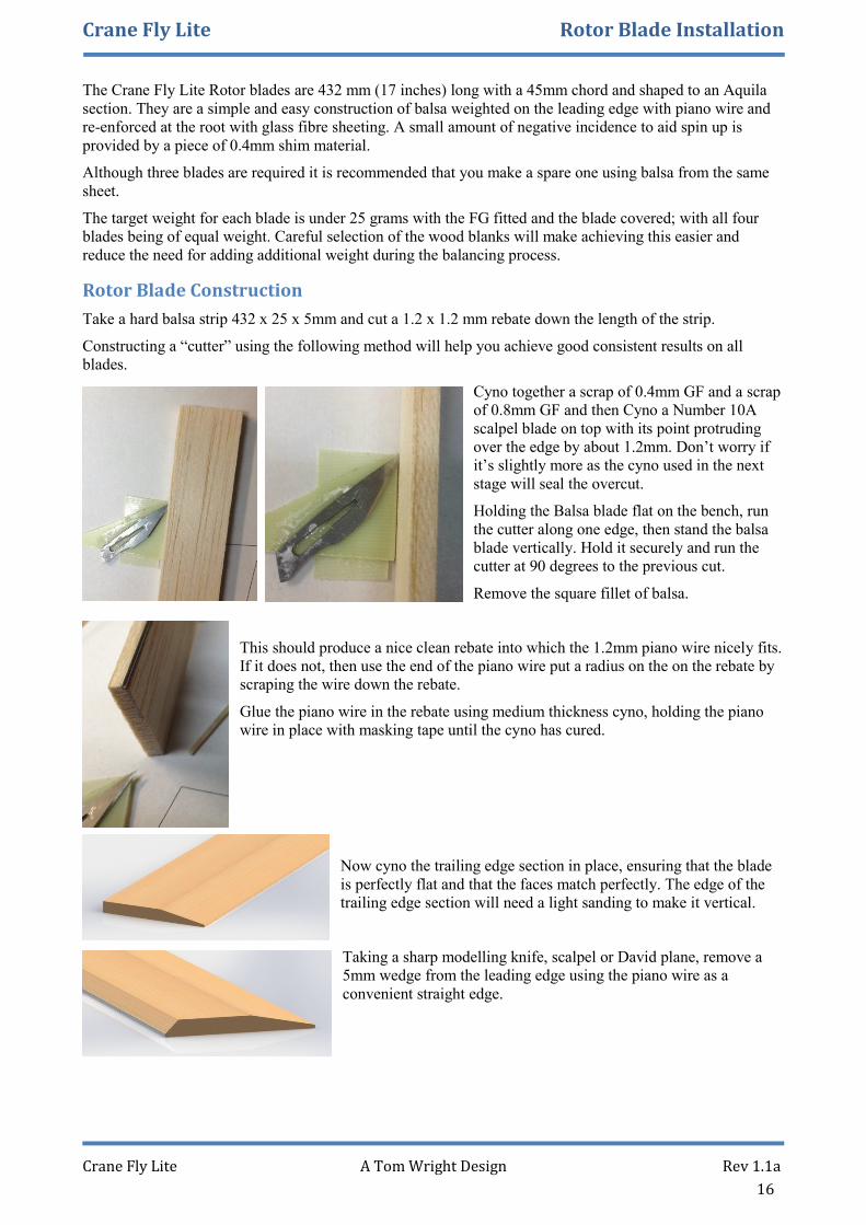
Rotor Blade Construction
Take a hard balsa strip 432 x 25 x 5mm and cut a 1.2 x 1.2 mm rebate down the length of the strip.
Constructing a “cutter” using the following method will help you achieve good consistent results on all
blades.
Cyno together a scrap of 0.4mm GF and a scrap
of 0.8mm GF and then Cyno a Number 10A
scalpel blade on top with its point protruding
over the edge by about 1.2mm. Don’t worry if
it’s slightly more as the cyno used in the next
stage will seal the overcut.
Holding the Balsa blade flat on the bench, run
the cutter along one edge, then stand the balsa
blade vertically. Hold it securely and run the
cutter at 90 degrees to the previous cut.
Remove the square fillet of balsa.
This should produce a nice clean rebate into which the 1.2mm piano wire nicely fits.
If it does not, then use the end of the piano wire put a radius on the on the rebate by
scraping the wire down the rebate.
Glue the piano wire in the rebate using medium thickness cyno, holding the piano
wire in place with masking tape until the cyno has cured.
Now cyno the trailing edge section in place, ensuring that the blade
is perfectly flat and that the faces match perfectly. The edge of the
trailing edge section will need a light sanding to make it vertical.
Taking a sharp modelling knife, scalpel or David plane, remove a
5mm wedge from the leading edge using the piano wire as a
convenient straight edge.

Crane Fly Lite Rotor Blade Installation
Crane Fly Lite A Tom Wright Design Rev 1.1a
17
Then using a long sanding block sand the rotor to give the section shown in the photo below.
Note that the trailing edge is thinned down to
1mm and that the maximum thickness is 5mm
at about 25% chord.
Shaping the blades is NOT a difficult task. Start by reducing the trailing edge thickness to 1mm, by holding
the sanding block flat against the top surface of the Trailing edge section taking the same amount of wood
off the whole width of it. Then round off the leading edge and gently blend the top surface to give the desired
section.
Blade Root Re-enforcement
Remember that the blades turn anti-clockwise, so with the blades
pointing away from you and the leading edge on the left-hand side
then the blade root is closest to you.
On the top of the blade, at the root, draw a line at the one third chord
position from the leading edge. Use this line to position and glue the
topside GF re-enforcement centrally over the line.
Now attach the underside GF re-enforcement, so that the square edge
of the re-enforcement is towards the leading edge as shown in the
picture below.
Trim the trailing edge to shape
(approx. 50 mm off cut) and drill the
3mm fixing hole as vertical as
possible through the blade from the
top surface. (Use a pillar drill if
available).
Shims
Finally add the small 0.4mm GF
shim piece on the underside 4mm
from the hole centre towards the
trailing edge.
This completes the rotor Blade Construction.

Crane Fly Lite Rotor Blade Installation
Crane Fly Lite A Tom Wright Design Rev 1.1a
18
Blade Balancing
The final task is to balance the blades. The closer in weight and
balance the better, as this reduces vibration when the blades are
spinning.
Chord-wise Balance
Checking and adjusting the blade balance chord-wise is not
necessary on such light blades with a wire leading edge. The weight
of the piano wire leading edge pretty much guarantees it will be in a
good position.
Length-wise Balance
Using a sensitive digital weigh-scale (resolution of 0.1g or better), weigh all the blades accurately. On each
blade write its weight (in pencil) on the GF.
Tape a round pencil or a 300mm length of 6mm dowel to your bench. You will use this to lay the blades
across it like a child’s See-Saw to find the length-wise balance positions.
Lay the heaviest blade on the See-Saw and find the point where it balances.
Lay another blade next to it, and adjust its balance point by adding weight (tape or PVA glue) close
to the Root or Tip until it balances at the same point (or with 2mm) as the heavy blade.
Repeat this process for all blades using your original heavy blade as a reference.
Weigh all the blades again, and write their weights on the GF. (rub out the old pencil mark)
The (new) heaviest blade becomes your reference blade.
Add weight (tape) to the lighter blades at their balance points to bring them up to the same weight as
your reference blade.
You should now have a complete set of blades all with the same weights and the same balance points.
Blade Covering
The blades can now be covered, sealing in the balance
weights, using a lightweight coloured self-adhesive tape and
fibre tape on the leading edge.
Note the sequence of applying the covering. This ensures that
the edges of the tape are not exposed to the oncoming wind.
Rotor Blade Installation
The Rotor blades can now be installed on the Model. Double
check that you have added the 0.4mm shims towards the rear
edge of the blades.
The Rotors are attached using M3x 16mm Hex Cap screws
with large 10-12mm diameter M3 washers all secured with
M3 Locknuts.
The tightening of the bolts needs to be done carefully, as the rotors need to be free enough to be able to move
in spin-up and find their own positions using centrifugal force, but tight enough so that they do not move
when the model is held up at an angle during initial spin-up.
Crane Fly Lite Flight Notes
Crane Fly Lite A Tom Wright Design Rev 1.1a
19
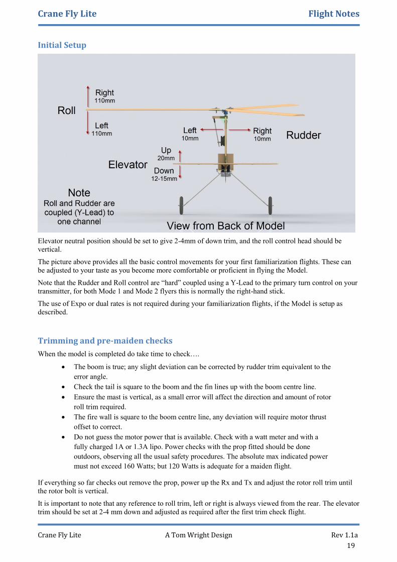
Initial Setup
Elevator neutral position should be set to give 2-4mm of down trim, and the roll control head should be
vertical.
The picture above provides all the basic control movements for your first familiarization flights. These can
be adjusted to your taste as you become more comfortable or proficient in flying the Model.
Note that the Rudder and Roll control are “hard” coupled using a Y-Lead to the primary turn control on your
transmitter, for both Mode 1 and Mode 2 flyers this is normally the right-hand stick.
The use of Expo or dual rates is not required during your familiarization flights, if the Model is setup as
described.
Trimming and pre-maiden checks
When the model is completed do take time to check….
The boom is true; any slight deviation can be corrected by rudder trim equivalent to the
error angle.
Check the tail is square to the boom and the fin lines up with the boom centre line.
Ensure the mast is vertical, as a small error will affect the direction and amount of rotor
roll trim required.
The fire wall is square to the boom centre line, any deviation will require motor thrust
offset to correct.
Do not guess the motor power that is available. Check with a watt meter and with a
fully charged 1A or 1.3A lipo. Power checks with the prop fitted should be done
outdoors, observing all the usual safety procedures. The absolute max indicated power
must not exceed 160 Watts; but 120 Watts is adequate for a maiden flight.
If everything so far checks out remove the prop, power up the Rx and Tx and adjust the rotor roll trim until
the rotor bolt is vertical.
It is important to note that any reference to roll trim, left or right is always viewed from the rear. The elevator
trim should be set at 2-4 mm down and adjusted as required after the first trim check flight.
Crane Fly Lite Flight Notes
Crane Fly Lite A Tom Wright Design Rev 1.1a
20
Next ensure the rotor spins freely and the retaining nut is secure, use thread lock if necessary. If the delta
plate has been made accurately and the simple blade balancing procedure has been carried out, the rotors
should spin up readily after a hand start and a walk forward with the model held back at least 45 degrees.
If any vibration is present, or spin up is not smooth and progressive then you could have the rotors bolted
down too tightly, if this is the case there could be insufficient force to overcome the bolt tension which will
not allow the blades to find their natural position after reaching operating speed. A little practice getting the
blade bolt tensions reasonably equal and yet sufficient to hold the blades in place during the hand start and
run up to speed will ensure the most efficient vibration free performance.
Practice walking forward with the model held well back, and ensuring the blades are a safe distance from
your head! Get used to the sound and feel of the rotor reaching operating speed or as its better known
autorotation. If a swishing sound cannot be heard then attempting a launch will result in a quick turn to the
left into the deck. If everything checks out fine read though the next section that covers the suggested
procedure for the first flight attempt.
First Flight
When the model is built and set up to plan, and everything is carefully checked, the last thing to do is rush to
the field and attempt a full power launch. At this point it’s worth saying that this model is only intended for
hand launching and is designed to be flown with the rudder coupled with roll. By far the best way of
achieving success is to look at the possibility of getting a properly experienced Auto gyro pilot to help out
with the maiden and monitor your first few solo attempts. There are also regular Auto gyro events crammed
with knowledgeable and experienced pilots who will be willing to help out.
When arriving at the field check the wind conditions and aim for a light breeze 2-5 mph, should give easy
spin up for hand launch. Next check the position of the sun relative to the into wind heading, this is
important as glare from the side or directly in front of the operating area will make disorientation far more
likely. If the wind is direction is steady try and identify a distant object as an into wind reference point, or if
the wind is light and variable check every time before each flight. It all sounds like simple common sense but
it's surprising how often things get forgotten in the heat of the moment.
Next consider the safety of onlookers or club mates, I have seen a first attempt resulting in a 180 degree turn
back towards the pilot and onlookers so consider all the possibilities and select a safe area. If a helper is hand
launching for you make sure they have had time to familiarize themselves with the feel of the model and the
sound of the rotors at auto rotation, also make absolutely sure that the model is held well clear of the helpers
head, and away from others.
Give the rotors a turn by hand and hold the model well up with the rotors angled at 45 degrees, or more, to
the oncoming wind, Identifying the sound when the rotors are up to speed is very important, if you are not
sure never attempt a launch. Rotors will normally make a swishing sound as they reach speed and you should
be able to feel an upward pull equal to the models weight.
If the model has been set up and trimmed correctly the first real flight should mainly involve gentle roll
inputs and manipulation of throttle and elevator, but the first thing to establish is the amount of power
required to get away, and the amount of forward push needed. If the model is held vertically and power
progressively applied you will feel the model getting lighter note the throttle position as a guide to the launch
power setting. As for the amount of "bung" energy required this should not be excessive or too feeble, lighter
models are capable of rising from your hand into a breeze with an appropriate power setting but for first
attempts a firm “bung” with the rotors up to speed and at a slightly nose up attitude should do the trick.
This is where the fun starts as some quick assessments need to be made with measured control inputs applied
to keep things in order. If the model is climbing straight ahead at a fairly high power setting then it will soon
get to a distance were the first turn will be too fast and too far away, so as soon as a safety height of 30-50 ft
is reached start by progressively reducing throttle, and lowering the nose to the point where the model is
maintaining height and travelling at a nice steady speed equivalent to a slow cruise, unless you are a very
confident pilot, at this stage, trimming via the Tx will cause an unwanted distraction, so if the model is still
fast hold a little up in and re adjust power, and if possible land straight ahead by reducing power
progressively and using the elevator to flare as terra firma approaches. Should the landing be less than
perfect then give the model a good check over before a further attempt is made.

Crane Fly Lite Flight Notes
Crane Fly Lite A Tom Wright Design Rev 1.1a
21
It is likely that the first attempt will involve some use of roll and pitch trim correction; if this is applied to
coarsely while the model is tearing about at speed then you will be lucky to recover the model. These early
sorties should be all about establishing a steady low cruise speed, and establishing if trim adjustments are
needed to avoid holding in roll or pitch on sticks. When correct trim settings have been established don't
expect to be flying hands off while chatting to mates, full concentration and focus will be needed throughout
all early flights to avoid disorientation.
If you find the model climbing out ok but pulling left or right, hold on the sticks, then progressively reduce
the power and land. A model out of trim in roll, or pitch is very difficult to fly particularly for a first Auto
gyro flight.
Excessive speed and distance away from the pilot are the first major factors that determine success or failure,
add in glare, and distraction, to set up the ideal conditions for unrepeatable utterances, and a damaged model.
Good sun glasses and a distraction free environment are as important as controlling speed.
Many pilots prefer a left hand circuit direction, if this is you, then start by only making turns to the left and
trimming the model for a gentle left turn; this idea should greatly help with orientation as the model should
always be turning left. Just a slight nudge on the stick should produce a bank, if the control input is too
course the bank angle should be restricted by short applications of opposite stick but be careful not to over
control or let the nose drop. Very gentle turns can be achieved without use of elevator but initiating a bank
and then neutralizing the stick while applying back stick and a touch more power should get you around ok.
If you are finding the first minute in the air stressful reduce power progressively and land to take stock of
what may be needed for a more relaxed flight.
This may to some seem hard work but believe me when I say; flying these machines can be very easy indeed
it's just a matter of developing an instinctive feel, and a little practice. Most pilots find that maintaining
orientation is a problem during early flights and later if over confidence creeps in.
Keeping the model reasonably close in, at a steady speed, helps with control and orientation, as does the old
method of standing side on to the direction of flight.
Maintaining focus on one part of the model also seems to help, I tend to follow the tail but a well-defined
part of the decor can also be used is a focal point. Many employ bright contrasting colours, but the
effectiveness does depend on the light conditions, and the viewing angle between the pilot and model.

205
50
85°
85°
4.4
Fuselage Base
2 Reguired
HALF SCALE
51x37mm
Fusalage Side
Firewall
Rear Former
A4
SHEET 1 OF 4
6mm (1/4")Balsa PartsSCALE:1:1
37
6.50
Cable ExitCutout addedduringconstruction
50
50
6.50
330
38 18
4
5
51

3mm BalsaFin
3mm BalsaTail-Plane
ElevatorOnly half shownElevator is built inone piecePlease Mirrorthis drawing
Rudder
See Construction notesfor details of carvedRudder Control Arm slot
32
124
13
BB
Elevator304 x 50 mm
50
69
77°
132
10
50
276
SECTION B-B
SHEET 2 OF 4
3mm (1/8")Balsa Parts

R30
Mast Side
Rotor Blade Upper
Rotor Blade ShimRotor Blade Lower
Rotor Blade Parts
Firewall
2 of each requiredControl Arm Components
PlateRudder Control Arm
Rudder Components
Rudder
2 off requiredMast Support
2 off
Mast Components
2required
SHEET 3 OF 4
Glass Fibre Parts A4
SCALE:1:1
3
10
12
25 30
38
72°
30
5
MastServo Mount
35
35
12.50
25
6.50
47.90
4
3
25
12.5 25
6.50
30
6.50
Delta Plate MUST beDelta Plate MUST beDelta Plate MUST beDelta Plate MUST bemade from 0.8mm (1/32")made from 0.8mm (1/32")made from 0.8mm (1/32")made from 0.8mm (1/32")
Glass Fibre SheetGlass Fibre SheetGlass Fibre SheetGlass Fibre Sheet
102
50
56.5
18
2
Elevator Brace & Rib
12
68
43°
27
30
15
Mast Top
40
50
85°
TailplaneSupport
50
40
Undercarriage Mount
18
48
60
40 12.5

Leg length 175 mmAxle length 20 mmTotal Wire length 480 mm
Piano Wire diameter 2.5 mm
Tailskid, Elevator & Ruddercontrol rods - all 1.2mm
Shown Full size
Wire PartsSHEET 4 OF 4
Side View1/2 Scale
20 degreeraked forward
1/2 Scale3D View
Undercarriage
Front View1/2 Scale
320
Top View bend DetailActual Size