CRANE BS&U supporting the Building Services Industry · CRANE BS&U supporting the Building Services...
40
1 Andy Lucas Technical Development Manager CRANE BS&U CRANE BS&U supporting the Building Services Industry
Transcript of CRANE BS&U supporting the Building Services Industry · CRANE BS&U supporting the Building Services...
1Andy LucasTechnical Development Manager CRANE BS&U
CRANE BS&U supporting the Building Services
Industry

2
Crane Co founded in 1855 by Richard Teller Crane who made the following resolution -
“I am resolved to conduct my business in the strictest honesty and fairness; to avoid all deception and trickery; to deal fairly with both customers and competitors; to be liberal and just towards employees; and to put my whole mind upon the business”
Crane Limited founded in Ipswich in 1919
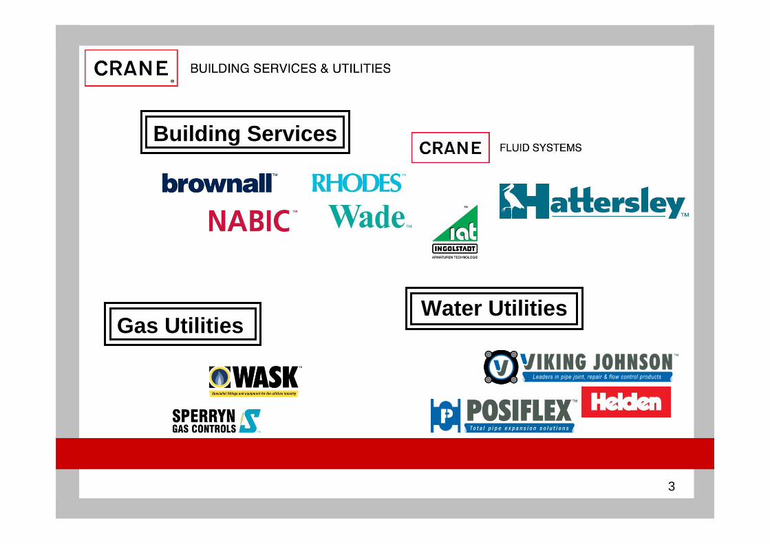
Crane Building Services & Utilities created 2009
3
Building Services
Water UtilitiesGas Utilities
4
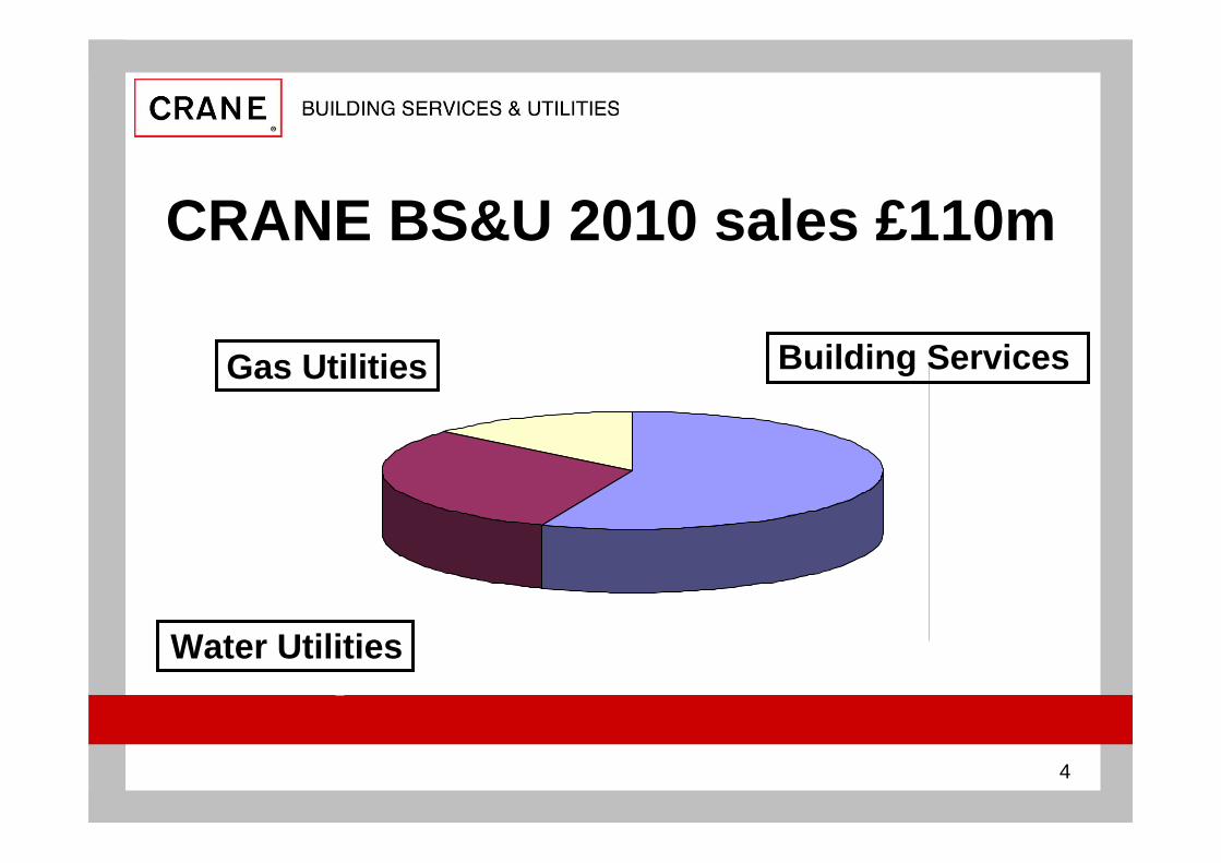
CRANE BS&U 2010 sales £110m
Gas Utilities Building Services
Water Utilities

5
industry organisations
• CIBSE
• SoHPE
• BSRIA
• CSA

6Andy LucasTechnical Development Manager CRANE BS&U
CIBSE approved CPD
Introduction to Safety Valves
7
An introduction to Safety Valves
To give an understanding of Safety Valves used in Building Services including
• sizing • installation• maintenance
Title
Objective

8
What are they?
Safety Valves
Definition (PED)
PED
Standard
Pressure Equipment Directive 97/23/EC • the regulation covering safety valves in Europe• safety valves are classified PED category IV
EN ISO 4126 - joint European & ISO standard
BS6759 – valve manufactured to BS6759 are deemed to comply with EN ISO 4126 if no design changes
‘a valve which automatically, without the assistance of any energy other than that of the fluid concerned, discharges a quantity of the fluid so as to prevent a predetermined safe pressure being exceeded, and which is designed to reclose and prevent further flow of fluid after normal pressure conditions of service have been restored’

9
Safety Valves
Safety valves, as the name implies, have a specific function
to protect equipment & personnel
EN ISO 4126 only refers to safety valves & covers
• safety valves
• relief valves
• pressure relief valves
• safety relief valves
What are they?

10
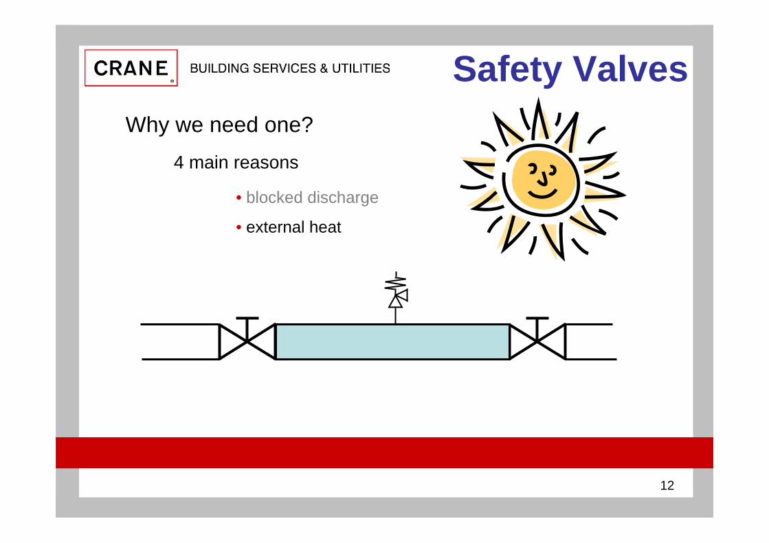
Safety ValvesWhy we need one?
• blocked discharge
• external heat
• thermal expansion
• failure of pipeline component, ie control valve
4 main reasons

11
Safety ValvesWhy we need one?
• blocked discharge
4 main reasons
safety valve
no flow
12
Safety ValvesWhy we need one?
• blocked discharge
• external heat
4 main reasons

13
Safety ValvesWhy we need one?
• blocked discharge
• external heat
• thermal expansion
4 main reasons

14
Safety ValvesWhy we need one?
• blocked discharge
• external heat
• thermal expansion
• failure of pipeline component, ie control valve
4 main reasons
no flow

15
Safety ValvesTerminology
Set pressure the pressure at which the valves starts to open measured at valve inlet normally 1.1 x working pressure or working pressure + 0.7 bar for water whichever is the greater
Overpressure pressure at which valve has to achieve its full discharge capacity normally set pressure +10%
Accumulation pressure increase over the maximum working pressure of the system during discharge through the safety valve

16
Safety ValvesOperating states
1. Equilibrium
2. Fully open
3. Fully closed
there are 3 operating states for safety valves
17
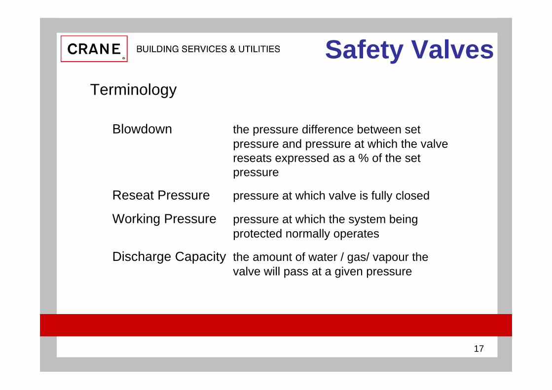
Safety ValvesTerminology
Blowdown the pressure difference between set pressure and pressure at which the valve reseats expressed as a % of the set pressure
Reseat Pressure pressure at which valve is fully closed
Working Pressure pressure at which the system being protected normally operates
Discharge Capacity the amount of water / gas/ vapour the valve will pass at a given pressure

18
Safety ValvesEquilibrium
forces acting to close are in equilibrium (balance) with the forces acting to open and the seat & disc are just in contact
defined in EN ISO 4126 as the Set Pressure
this is the point when flow is about to start
in practice flow commences as the equilibrium point is reached
P system
P spring
P system = P spring

19
Safety ValvesFully open
the position the valve must achieve to pass its rated capacity at its specified overpressure
note - this is not the Set Pressure
different designs of valve have different relationship between flow & pressure
some designs have a rapid increase in flow for a small increase in pressure -others offer a gradual increase
P system + overpressure
P spring
P system + overpressure = P spring

20
Safety ValvesFully closed
the position when the valve has re-seated ie fully closed - nil leakage
the difference between the re-seat pressure & set pressure is often referred to as the Blowdown Pressure
the blowdown pressure will depend on valve design, the faster the flow increases on opening the lower the blowdown pressure is P system
P spring
P re-seat = P system - blowdown

21
Safety ValvesDirect Spring Safety Valve
within Building Services the Direct Spring Safety valve is generally used
the spring is pre-compressed to apply force downwards on the disc holding it onto the seat to maintain a pressure seal
if the system pressure increases the spring force is exceeded & flow commences

22
Safety ValvesDirect Spring Safety Valve
seat
disc
stem
adjustereasing lever
spring
body
bonnetDirect Spring
with easing lever

23
Safety ValvesDirect Spring Safety Valve
seat
disc
stem
adjuster
topworks enclosure
spring
body
bonnet
Direct Spring with topworks enclosure
lock nut

24
Safety ValvesCombined Pressure & Temperature
Direct Spring Safety Valve with temperature funtion
the spring is pre-compressed to apply force downwards on the disc holding it onto the seat to maintain a pressure seal
if the system pressure or temperature increases the spring force is exceeded & flow commences temperature
sensor

25
Safety Valves
seat
disc
stem
adjustereasing lever
spring
body
bonnetDirect Spring Combined Pressure & Temperature
with easing lever
Combined Pressure & Temperature
temperature sensor

26
Safety ValvesSizing
sizing affects how a Safety Valve performs
correct sizing of Safety Valves is important
• undersize valves may not relieve sufficient quantity of system media to prevent pressure build-up
• oversized valves will partially lift at set pressure & then re-seat so could cause ‘chattering’ of the disc damaging the seat / disc surfaces

27
Safety ValvesSizing
requirements for sizing Safety Valves are
What is the application
What is the set pressure
What is the discharge capacity required
28
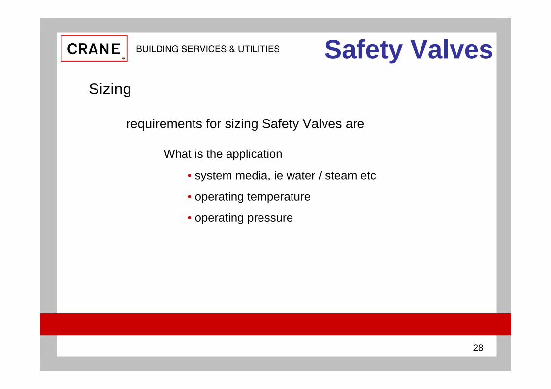
Safety ValvesSizing
requirements for sizing Safety Valves are
What is the application
• system media, ie water / steam etc
• operating temperature
• operating pressure

29
Safety ValvesSizing
requirements for sizing Safety Valves are
What is the application
What is the set pressure
• the pressure at which the valves starts to open measured at valve inlet
normally 1.1 x working pressure or
working pressure + 0.7 bar for water whichever is the greater

30
Safety ValvesSizing
requirements for sizing Safety Valves are
What is the application
What is the set pressure
What is the discharge capacity required
• the amount of water / gas / vapour required to discharge at a given pressure

31
Safety ValvesInstallation
installed position of the Safety Valve affects how the Safety Valve performs
mount vertically
avoiding
• long pipework runs to Safety Valves
• valves between system & Safety Valve
• fittings / bend between Safety Valve and system
• installation near to pipework lateral connections
• inverted outlet

32
Safety ValvesInstallation
• long pipework runs to Safety Valves
pipework losses between protected system & Safety
Valve should not be greater than 3% of maximum
discharged capacity pressure

33
Safety ValvesInstallation
• long pipework runs
• valves between system & Safety Valve
under no circumstances should valves be installed between safety Valve &
protected system
34
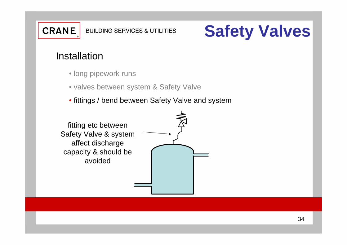
Safety ValvesInstallation
• long pipework runs
• valves between system & Safety Valve
• fittings / bend between Safety Valve and system
fitting etc between Safety Valve & system
affect discharge capacity & should be
avoided

35
Safety ValvesInstallation
• long pipework runs
• valves between system & Safety Valve
• fittings / bend between Safety Valve and system
• installation near to pipework lateral connections
flow into lateral pipework affects system
pressure at Safety Valve inlet
36
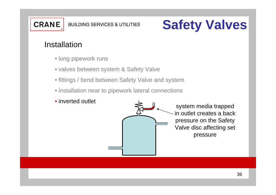
Safety ValvesInstallation
• long pipework runs
• valves between system & Safety Valve
• fittings / bend between Safety Valve and system
• installation near to pipework lateral connections
• inverted outletsystem media trapped in outlet creates a back pressure on the Safety Valve disc affecting set
pressure
37
Safety ValvesMaintenance
regular maintenance ensures
• Safety Valve will work when required
• life of valve
• system is correctly protected from over pressure
• compliance with insurance company requirements
38
Safety ValvesMaintenance
• the mechanical operation should be checked at three monthlyintervals by manually operating the easing lever
see installation instructions supplied with valve • to avoid unnecessary strain on the easing gear, the valve should
be under a pressure of not less than 75% of its set pressure• where arduous conditions of service exist, more frequent testing
may be required
It is the responsibility of the user to establish the frequency of manual testing
maintenance regime should include

39
Safety ValvesMaintenance
before removing the valve, steps should be taken to ensure that the system has been de-pressured
the set pressure of Safety Valves should be checked every twelve months
• this can be carried out in situ
• usually difficult on site as gauges need to be calibrated and system pressure needs to be varied to check set pressure
• by removal of the Safety Valve to a test facility

40Andy LucasTechnical Development Manager CRANE BS&U
CIBSE approved
Introduction to Safety Valves