CraftSmart Test Access Point (TAP) Box · and access of the fiber - to determine feeder and drop...
17
CraftSmart ® Test Access Point (TAP) Box Installation Manual ______________________________________________________ Manual 020016 REV A - Sept 2018
Transcript of CraftSmart Test Access Point (TAP) Box · and access of the fiber - to determine feeder and drop...

CraftSmart® Test Access Point (TAP) BoxInstallation Manual ______________________________________________________
Manual 020016 REV A - Sept 2018

Direct: 763.476.6866 • National: 800.422.2537 • www.SeeClearfield.com • [email protected] 2
CraftSmart® Test Access Point (TAP) BoxInstallation Manual _________________________________________________________
Manual 020016 REV A - Sept 2018
Table of ContentsApplication 3Description 3Technical Specifications 3TAP Box Assembly 4TAP Box Mounting 8Cable Entrance 10Grounding 11Strength Member Clamp 11Cable Routing 12Connector Cleaning Procedure 13Standard Warranty 16Proprietary Notice 17Technical Support 17

3
CraftSmart® Test Access Point (TAP) Box__________________________________________________________ Installation Manual
Direct: 763.476.6866 • National: 800.422.2537 • www.SeeClearfield.com • [email protected] Manual 020016 REV A - Sept 2018
Description
Application
Technical Specifications
The CraftSmart Test Access Point (TAP) Box gives the service provider an accessible exterior access point to test fiber integrity before it enters the customer premise. This solution allows the service provider the ability to identify potential issues in conductivity from outside of the customer premise location.
The CraftSmart TAP Box is a two part closure that will accommodate up to four fibers for test and access purposes. The base of the unit will allow up to four splices from the feeder cable to individual drops into the customer premise. Duplex SC adapters allow for installation of pre-terminated or field terminated fiber to be connectorized for test and access of the fiber - to determine feeder and drop issues.
Two grommeted in/out ports on the bottom of the unit provide easy installation of both feeder and drop cables. The unit is lockable to minimize customer tampering. There are grounding options available inside the TAP Box that will allow grounding of the feeder and drop cables. It also has built in access to exterior grounding built into the unit. Multiple mounting options are available to meet all applications. The TAP box is available with private labeling on thefront cover to easily identify service provider’s identification.
CraftSmart Test Access Point (TAP) BoxDimensions 7.3” H x 8.57” W x 1.67” D
Connector Availability/Capacity
Empty: No connectorOne dual SC/APC or SC/UPC; two dual SC/APC or SC/UPC; quad LC/UPC or LC/APC; two quad LC/UPC or LC/APC
Cable Support and Tie Off Options
Not included with TAP Box - MUST BE ORDERED SEPARATELY.TAP-GL-KIT (one clamp per kit) Strength member tie off kit for flat drop and dielectric cableTAP-ARM-GL-KIT (one clamp per kit) Ground lug bracket for armored cable - no strength member tie off
Splice Capacity FourCable Entrance/Exit One on each port (two total). If using FieldShield® Microduct, order one FS-CPLR-10MM-10MM-TAP per exit
Private Labeling Standard: comes with Clearfield® logo.Private labeling available (500 piece minimum). Contact Clearfield sales representative for details
Pre-terminated Feeder and Drop Cable Available: Please contact your Clearfield sales representative
Mounting OptionsWall Mount: StandardVinyl Siding Mount: TAP-VS-KITPole Mount: TAP-PM-KIT

Direct: 763.476.6866 • National: 800.422.2537 • www.SeeClearfield.com • [email protected] 4
CraftSmart® Test Access Point (TAP) BoxInstallation Manual _________________________________________________________
Manual 020016 REV A - Sept 2018
TAP Box Assembly
The Tap Box will arrive as shown. Remove the cover by sliding it off. Small parts will be contained inside, set them aside.
TAP Box will appear as shown. You will need a side cutters or pair of snips to remove the molded plastic pieces attached at the base of the box.
Clip at the spots highlighted.
Proceed to clipping the pieces from the molding spur. Pieces should include:
1. Large cable management retainers (Qty 4)2. Duplex SC adapter holder3. Bridge lances/cable tie downs (Qty 2)4. Small cable management retainers (Qty 4)
2 431
1.
2.
3.

5
CraftSmart® Test Access Point (TAP) Box__________________________________________________________ Installation Manual
Direct: 763.476.6866 • National: 800.422.2537 • www.SeeClearfield.com • [email protected] Manual 020016 REV A - Sept 2018
Install the 4 large cable management retainers (round peg) into the top outside posts.
Install the 4 small cable management retainers (square peg) into the lower inside posts.
4.
5.

Direct: 763.476.6866 • National: 800.422.2537 • www.SeeClearfield.com • [email protected] 6
CraftSmart® Test Access Point (TAP) BoxInstallation Manual _________________________________________________________
Manual 020016 REV A - Sept 2018
Using the supplied VHB tape, secure the two cable tie downs (bridge lances) into place inside the TAP Box. Tie down locations exist above and below the splicing area. These will be used to secure the cable before splicing.
Snap the splice tray cover into place. If you plan to splice inside the TAP Box later, the cover will protect the splices.
6.
7.

7
CraftSmart® Test Access Point (TAP) Box__________________________________________________________ Installation Manual
Direct: 763.476.6866 • National: 800.422.2537 • www.SeeClearfield.com • [email protected] Manual 020016 REV A - Sept 2018
Place the adpater into the holder, and install it into the TAP Box at the top.
Note: If you are not utilizing the lower adapter slot of the holder you may clip the piece to provide a path for cable to run underneath.
8.
Trim the black cable entrance plugs, separating them. Place them into the entrances of the TAP Box. These can be used to provide a weather seal around the cable. If utilizing microduct and a coupler (P/N FS-CPLR-10MM-10MM-TAP) to bring cable into the TAP these may not be used.
9.

Direct: 763.476.6866 • National: 800.422.2537 • www.SeeClearfield.com • [email protected] 8
CraftSmart® Test Access Point (TAP) BoxInstallation Manual _________________________________________________________
Manual 020016 REV A - Sept 2018
TAP Box Mounting
Wall Mount
The TAP Box can be mounted to a wall using standard hardware and the provided holes
Mounting holes
Vinyl Siding Mount
Siding clips (P/N TAP-VS-KIT) will be attached to the TAP Box with 2 barbed push fasteners per clip. TAP can then be hung from siding.

9
CraftSmart® Test Access Point (TAP) Box__________________________________________________________ Installation Manual
Direct: 763.476.6866 • National: 800.422.2537 • www.SeeClearfield.com • [email protected] Manual 020016 REV A - Sept 2018
Pole Mount
The Pole Mount Bracket (P/N TAP-PM-KIT) can be attached to many different types of surfaces. Once attached, the TAP box can be secured to the bracket with normal hardware and the 4 provided mounting holes.
4 x 4 Post
Tube Clamp - 3” Pipe U-Bolt - 3” Pipe
Sign Post

Direct: 763.476.6866 • National: 800.422.2537 • www.SeeClearfield.com • [email protected] 10
CraftSmart® Test Access Point (TAP) BoxInstallation Manual _________________________________________________________
Manual 020016 REV A - Sept 2018
Cable Entrance
The TAP Box accepts a pushable fiber quick connect coupler. The coupler can be zip tied into place and duct inserted into the coupler. Cable can then be fed through the duct and into the TAP Box.
If not utilizing a coupler, cut two perpendicular slits in the center of the black cable entrance plug, and feed the cable through the plug. Then wrap the cable with grommet tape (foam tape) below the plug and secure it into place on the TAP Box with a zip tie. Insert the plug into place on the TAP just above.

11
CraftSmart® Test Access Point (TAP) Box__________________________________________________________ Installation Manual
Direct: 763.476.6866 • National: 800.422.2537 • www.SeeClearfield.com • [email protected] Manual 020016 REV A - Sept 2018
Grounding
If utilizing armored cable, an optional ground lug bracket for armored cable is available (P/N TAP-ARM-GL-KIT). Ground per your local rules and practices
Strength Member Clamp
For dielectric cable and flat drop cables, a strength member clamp can be used (P/N TAP-GL-KIT).

Direct: 763.476.6866 • National: 800.422.2537 • www.SeeClearfield.com • [email protected] 12
CraftSmart® Test Access Point (TAP) BoxInstallation Manual _________________________________________________________
Manual 020016 REV A - Sept 2018
The TAP can be secured with either a lock or a security tab through the hole at the front of the box.
Cable Routing
Radius protected slack management allows cable to be safely stored as it transitions from the entry to the mating point
A cable exit is located at the bottom of the TAP Box which provides covered access to the inside of the building the box is mounted to.
Cable tie downs, attached via VHB tape, can be used to secure the fiber prior to splicing.
13
CraftSmart® Test Access Point (TAP) Box__________________________________________________________ Installation Manual
Direct: 763.476.6866 • National: 800.422.2537 • www.SeeClearfield.com • [email protected] Manual 020016 REV A - Sept 2018
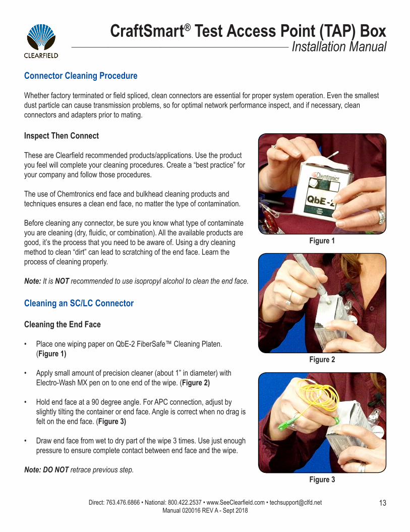
Inspect Then Connect These are Clearfield recommended products/applications. Use the product you feel will complete your cleaning procedures. Create a “best practice” for your company and follow those procedures.
The use of Chemtronics end face and bulkhead cleaning products and techniques ensures a clean end face, no matter the type of contamination.
Before cleaning any connector, be sure you know what type of contaminate you are cleaning (dry, fluidic, or combination). All the available products are good, it’s the process that you need to be aware of. Using a dry cleaning method to clean “dirt” can lead to scratching of the end face. Learn the process of cleaning properly.
Note: It is NOT recommended to use isopropyl alcohol to clean the end face.
Cleaning an SC/LC Connector
Cleaning the End Face
• Place one wiping paper on QbE-2 FiberSafe™ Cleaning Platen. (Figure 1)
• Apply small amount of precision cleaner (about 1” in diameter) with Electro-Wash MX pen on to one end of the wipe. (Figure 2)
• Hold end face at a 90 degree angle. For APC connection, adjust by slightly tilting the container or end face. Angle is correct when no drag is felt on the end face. (Figure 3)
• Draw end face from wet to dry part of the wipe 3 times. Use just enough pressure to ensure complete contact between end face and the wipe.
Note: DO NOT retrace previous step.
Figure 1
Figure 2
Figure 3
Connector Cleaning Procedure
Whether factory terminated or field spliced, clean connectors are essential for proper system operation. Even the smallest dust particle can cause transmission problems, so for optimal network performance inspect, and if necessary, clean connectors and adapters prior to mating.

Direct: 763.476.6866 • National: 800.422.2537 • www.SeeClearfield.com • [email protected] 14
CraftSmart® Test Access Point (TAP) BoxInstallation Manual _________________________________________________________
Manual 020016 REV A - Sept 2018
Cleaning the Ferrule
• Lightly moisten the fiber optic swab (2.5mm/38542F or 1.25mm/38040) by spotting a small amount (about 1”) of Electro-Wash PX or Electro-Wash MX pen onto the QbE. Hold the swab, 1 side down to the wetted area and hold for a count of 1-2-3-4-5. (Figure 4)
Figure 4
Figure 5
Figure 6
Cleaning the Mate Through an Adapter AND the Adapter Itself
• Lightly moisten the fiber optic swab (2.5mm/38542F or 1.25mm/38040) by spotting a small amount (about 1”) of Electro-Wash PX or Electro-Wash MX pen onto the QbE. Hold the tip of the swab onto the wetted area and hold for a count of 1-2-3-4-5.
• Insert the swab into the adapter to the connector, press lightly against the connector, twist 2-3 times, remove and discard.
• Dry with a second dry swab.
• Inspect, repeat cleaning if necessary, and test for signal strength.
• Use additional swabs to clean inside the actual adapter. Moisten swab, like above, and insert through hole and remove while twisting. (Figure 6)
• Insert swab into side of ferrule, wet side to the ceramic ferrule and circle around 2-3 times and remove. Turn swab to dry side and repeat. (Figure 5)

15
CraftSmart® Test Access Point (TAP) Box__________________________________________________________ Installation Manual
Direct: 763.476.6866 • National: 800.422.2537 • www.SeeClearfield.com • [email protected] Manual 020016 REV A - Sept 2018
Cleaning an MPO/MTP Connector
Female Connector
• Place one wiping paper on QbE-2 FiberSafe™ Cleaning Platen and apply small amount of precision cleaner (about 1” in diameter) with Electro-Wash MX pen on to one end of the wipe. (Figure 1)
Figure 1
Figure 2
Figure 3
• Hold end face at a 90 degree angle. For APC connection, adjust by slightly tilting the container or end face. Angle is correct when no drag is felt on the end face. (Figure 2)
Male Connector
• Lightly moisten one side of the fiber optic swab (CC505F) by spotting a small amount (about 1”) of Electro-Wash PX or Electro-Wash MX pen onto the QbE. Hold the swab, 1 side down to the wetted area and hold for a count of 1-2-3-4-5.
• Place swab, wet side down, at one end of connector end face and draw across in a diagonal sweep; i.e., from fiber 1 up and across to fiber 12. Turn swab over to dry and draw back from fiber 12 to fiber 1. (Figure 3)

Direct: 763.476.6866 • National: 800.422.2537 • www.SeeClearfield.com • [email protected] 16
CraftSmart® Test Access Point (TAP) BoxInstallation Manual _________________________________________________________
Manual 020016 REV A - Sept 2018
Standard WarrantyClearfield warrants to the original purchaser of the Product sold hereunder is free from defects in material and workmanship under normal use and service, subject to exceptions stated herein. Product purchased is warranted as follows: Clearfield designed and branded Products are warranted for three (3) years: Products manufactured by Clearfield to customer prints and/or specifications are warranted for one (1) year; and any Product Clear-field acquires from or through a third-party manufacturer or distributor and resells to Customer as the original customer will carry the manufacturer’s pass-through warranty, if any. In all cases, the warranty period commences on the date of shipment to the original purchaser.
Warranty Claim Procedure
If any Product purchased from Clearfield is found defective under the above warranty, the following basic procedure must be followed:
1. Customer must contact Clearfield and obtain a Return Materials Authorization2. Following authorization, the Customer ships the product-freight collect-to Clearfield’s manufacturing facility3. Clearfield shall repair or replace the defective Product at its sole option and discretion, and return the repaired or replacement Product to Cus-
tomer’s site, freight prepaid
Note: If the Product is not found to be defective by Clearfield, the product will be returned to the Customer and the customer billed for freight in both directions.
View our warranty policy here: https://www.seeclearfield.com/warranty.html
Limitations of Warranty
Correction of defects by repair or replacement, at the option of Clearfield Inc, shall constitute the exclusive sole remedy for a breach of this limited warranty. Clearfield shall not be liable under any circumstances for any special, consequential, incidental, punitive, or exemplary damages arising out of or in any way connected with the product or with agreement to sell product to buyer, including, but not limited to damages for lost profits, loss of use, or for any damages or sums paid by buyer to third parties. The foregoing limitation of liability shall apply whether the claim is based upon principles of contract, warranty, negligence or other tort, breach of statutory duty, principles of indemnity or contribution, the failure of any limited or exclusive remedy to achieve its essential purpose, or otherwise.
Clearfield will not be responsible for any labor or materials costs associated with installation or incorporation of Clearfield products at customer sites, including any costs of alteration, replacement or defective product, or any field repairs.
Other Limitations
Clearfield assumes no warranty liability regarding defects caused by:
1. Customer’s modification of Product, excepting installation activities described in Clearfield documentation2. Customer re-packaging of Product for shipment to third parties or destinations other than those originally shipped to by Clearfield, or any de-
fects suffered during shipping where the Product has been re-packaged3. Customer’s installation or maintenance, excepting activities described in and performed in accordance with Clearfield documentation4. Customer’s improper or negligent use or application of Product5. Other causes external to the Product, including but not limited to accidents, catastrophe, acts of God, government action, war, riot, strikes, civil
commotion, sovereign conduct, or the acts or conduct of any person or persons not party to or associated with Clearfield6. Environmental factors and weathering resulting in aging and damage not necessary or applicable to the function of the product

17
CraftSmart® Test Access Point (TAP) Box__________________________________________________________ Installation Manual
Direct: 763.476.6866 • National: 800.422.2537 • www.SeeClearfield.com • [email protected] Manual 020016 REV A - Sept 2018
Proprietary Notice
Information contained in this document is copyrighted by Clearfield, Inc. and may not be duplicated in full or part by any person without prior written approval of Clearfield, Inc.
Its purpose is to provide the user with adequately detailed documentation to efficiently install the equipment supplied. Every effort has been made to keep the information contained in this document current and accurate as of the date of publication or revision.
However, no guarantee is given or implied that the document is error free or that it is accurate with regard to any specification.
Technical Support
Clearfield, Inc. can be contacted for any issues that arise with the supplied product.
If you need to return the supplied product, you must contact the Clearfield, Inc. Customer Service Department to request a Returned Materials Authorization (RMA) number.
Clearfield, Inc.7050 Winnetka Ave NMinneapolis, MN 55428
Toll Free: 800.422.2537Phone: 763.476.6866Fax: 763.475.8457
Customer Support: [email protected] Support: [email protected]