Craftsman LT2000 Owner's Manual
60
Owner's Manual ICReFTSMeW,, I LAWN TRACTOR 17.0 HP, 42" Mower Electric Start 6 Speed Transaxle Model No. 917.273130 IMPORTANT: Read and follow all Safety Rules and Instructions before operating this equipment. For answers to your questions about this product, Call: 1-800-659-5917 Sears Craftsman Help Line 5 am - 5 prn, Mort - Sat Sears, Roebuck and Co., Hoffman Estates, IL 60179 U.S.A. Visit our Craftsman website:www.sears.comicraftsman
description
Craftsman LT2000 Owner Manual and parts list. Keep your Craftsman Lawn Tractor in tip-top condition with this manual.
Transcript of Craftsman LT2000 Owner's Manual

Owner's Manual
ICReFTSMeW,,ILAWN TRACTOR17.0 HP, 42" MowerElectric Start
6 Speed Transaxle
Model No.917.273130
IMPORTANT:Read and follow all SafetyRules and Instructionsbefore
operating this equipment.
For answers to your questions
about this product, Call:
1-800-659-5917Sears Craftsman Help Line5 am - 5 prn, Mort - Sat
Sears, Roebuck and Co., Hoffman Estates, IL 60179 U.S.A.Visit our Craftsman website:www.sears.comicraftsman
Jeff
Typewriter
deck pg 21

Warranty.................................................2 Maintenance.........................................17SafetyRules...........................................3 Serviceand Adjustments......................21ProductSpecifications............................6 Storage.................................................27AssemblyiPre-Operation........................8 Troubleshooting....................................28Operation..............................................11 RepairParts..........................................32MaintenanceSchedule.........................17 SearsService.........................BackCover
LIMITEDWARRANTYON CRAFTSMANRIDINGEQUIPMENTFortwo (2) years from the dateof purchase,if this CraftsmanRiding Equipmentismaintained,lubricatedand tuned upaccordingto the instructionsin the owner'smanual,Searswill repairor replacefree of chargeany parts that are foundto be defectiveinmaterialor workmanshipaccordingto the guidelinesof coveragelisted below.Searswillalso provide free labor for theseapplicablewarrantedparts for the two full years.Duringthe first 30 daysof purchase,there will be nochargesto service the product at yourhomefor issuescoveredby this warranty.(Seeexclusionsbelow). Foryourconve-nience, IN HOMEwarrantyservicewill still be availableafter the first 30 daysof pur-chase,but a trip chargewill apply.This chargewill be waived if the Craftsmanproductisdroppedoff at an authorizedSears location.Forthe nearestauthorizedSears location,pleasecall 1-800-4-MY-HOME®.This warrantyappliesonly while this productis withinthe UnitedStates.
ThisWarrantydoes notcover:• Expendableitemswhich becomeworn during normaluse, includingbutnot limitedto
blades,spark plugs,air cleaners,belts,and oil filters.• StandardMaintenanceServicing,oil changes, or tune-ups• Tire replacementor repaircausedby puncturesfrom outsideobjects,suchas nails,
thorns, stumps,or glass.• Repairsnecessarybecauseof operatorabuse, includingbut not limitedto,damage
causedby towingobjectsbeyondthe capabilityof the ridingequipment,impactingobjectsthat bendthe frameor crankshaft,or over-speedingthe engine.
• Repairsnecessarybecauseof operator negligence,includingbut not limitedto, elec-trical and mechanicaldamagecausedby improperstorage,failureto use the propergradeand amountof engineoil, failureto keepthe deckclear of flammabledebris,or failureto maintainthe equipmentaccordingto the instructionscontained in theowner'smanual.
• Engine (fuel system)cleaningor repairscausedbyfuel determinedto be contami-nated or oxidized(stale). Ingeneral,fuel shouldbe used within30 daysof its pur-chasedate.
• Normaldeteriorationand wear of the exteriorfinishes,or product label replacement.• Ridingequipmentusedfor commercialor rentalpurposes.LIMITEDWARRANTYON BATTERYForninety (90)days from dateof purchase, if any battery includedwith this ridingequip-mentprovesdefectivein materialor workmanshipand our testingdeterminesthe batterywill not holda charge,Searswill replacethe batteryat no charge. Duringthe first 30daysof purchase,therewill be no chargesto replacethe batteryat your HOME. Afterthe first 30 days,for yourconvenience,IN-HOMEwarrantyservicewill still be avail-able but a trip chargewill apply. This chargewill be waived if the Craftsmanproductisdroppedoff at an authorizedSears location.Forthe nearestauthorizedSears location,pleasecall 1-800-4-MY-HOME®.
This batterywarrantyappliesonly while this productis within the UnitedStates.
This warrantygivesyouspecific legal rights,and you mayalso haveother rights,whichvary,from state to state.
Sears, Roebuck and Co.,Dept.817WA, Hoffman Estates, IL 60179

IMPORTANT: This cutting machine is capable of amputating hands and feet and throw-ing objects. Failure to observe the following safety instructions could result in seriousinjury or death.
WARNING: In order to preventaccidental starting when setting up,transporting, adjusting or making repairs,always disconnect spark plug wire andplace wire where it cannot contact sparkplug.
WARNING: Do not coast down a
hill in neutral, you may lose control of thetractor.
_IbWARNING: Tow only the attach-
ments that are recommended by andcomply with specifications of the man-ufacturer of your tractor. Use commonsense when towing. Operate only at thelowest possible speed when on a slope.Too heavy of a load, while on a slope, isdangerous. Tires can lose traction withthe ground and cause you to lose controlof your tractor.
WARNING: Engine exhaust, someof its constituents, and certain vehiclecomponents contain or emit chemicalsknown to the State of California to causecancer and birth defects or other repro-ductive harm.
WARNING: Battery posts, terminalsand related accessories contain lead andlead compounds, chemicals known to theState of California to cause cancer andbirth defects or other reproductive harm.Wash hands after handling.
1.GENERAL OPERATION
• Read, understand, and follow all instruc-tions in the manual and on the machinebefore starting.
• Only allow responsible adults, who arefamiliar with the instructions, to operatethe machine.
• Clear the area of objects such as rocks,toys, wire, etc., which could be pickedup and thrown by the blade.
• Be sure the area is clear of other peoplebefore mowing. Stop machine if anyoneenters the area.
• Never carry passengers.• Do not mow in reverse unless abso-
lutely necessary. Always look down andbehind before and while backing.
• Be aware of the mower discharge direc-tion and do not point it at anyone. Donet operate the mower without eitherthe entire grass catcher or the guard inplace.
• Slow down before turning.• Never leave a running machine unat-
tended. Always turn off blades, setparking brake, stop engine, and removekeys before dismounting.
• Turn off blades when net mowing.• Stop engine before removing grass
catcher or unclogging chute.• Mow only in daylight or good artificial
light.• De net operate the machine while under
the influence of alcohol or drugs.• Watch for traffic when operating near or
crossing roadways.• Use extra care when loading or un-
loading the machine into a trailer ortruck.
• Data indicates that operators, age 60years and above, are involved in a largepercentage of riding mower-related in-juries. These operators should evaluatetheir ability to operate the riding mowersafely enough to protect themselves andothers from serious injury.
• Keep machine free of grass, leaves orother debris build-up which can touchhot exhaust / engine parts and burn. Donet allow the mower deck to plow leavesor other debris which can cause build-up to occur. Clean any oil or fuelspillage before operating or storing themachine. Allow machine to cool beforestorage.
11.SLOPE OPERATION
Slopes are a major factor related to loss-of-control and tipever accidents, which canresult in severe injury or death. All slopesrequire extra caution. If you cannot backup the slope or if you feel uneasy on it, donot mow it.
3

DO:• Mow up and down slopes, not across.• Remove obstacles such as rocks, tree
limbs, etc.• Watch for holes, ruts, or bumps. Un-
even terrain could overturn the machine.Tall grass can hide obstacles.
• Use slow speed. Choose a low gearso that you will not have to stop or shiftwhile on the slope.
• Follow the manufacturer's recommend-ations for wheel weights or counter-weights to improve stability.
• Use extra care with grass catchers orother attachments. These can changethe stability of the machine.
• Keep all movement on the slopes slewand gradual. Do not make suddenchanges in speed or direction.
• Avoid starting or stopping on a slope. Iftires lose traction, disengage the bladesand proceed slowly straight down theslope.
DO NOT:
• Do not turn on slopes unless neces-sary, and then, turn slowly and graduallydownhill, if possible.
• Do not mow near drop-offs, ditches,or embankments. The mower couldsuddenly turn over if a wheel is overthe edge of a cliff or ditch, or if an edgecaves in.
• Do notmow on wet grass. Reducedtraction could cause sliding.
• Do not try to stabilize the machine byputting your foot on the ground.
• Do not use grass catcher on steepslopes.
111.CHILDRENTragic accidents can occur if the operatoris not alert to the presence of children.Children are often attracted to the ma-chine and the mowing activity. Neveras-sume that children will remain where youlast saw them.• Keep children out of the mowing area
and under the watchful care of anotherresponsible adult.
• Be alert and turn machine off if childrenenter the area.
• Before and when backing, look behindand down for small children.
• Never carry children. They may fall offand be seriously injured or interfere withsafe machine operation.
• Never allow children to operate themachine.
• Use extra care when approaching blindcorners, shrubs, trees, or other objectsthat may obscure vision.
IV. SERVICE
• Use extra care in handling gasoline andother fuels. They are flammable andvapors are explosive.- Use only an approved container.- Never remove gas cap or add fuel
with the engine running. Allowengine to cool before refueling. Donot smoke.
- Never refuel the machine indoors.- Never store the machine or fuel
container inside where there is anopen flame, such as a water heater.
• Never run a machine inside a closedarea.
• Keep nuts and bolts, especially bladeattachment bolts, tight and keep equip-ment in good condition.
• Never tamper with safety devices.Check their proper operation regularly.
• Keep machine free of grass, leaves, orother debris build-up. Clean oil or fuelspillage. Allow machine to cool beforestoring.
• Stop and inspect the equipment if youstrike an object. Repair, if necessary,before restarting.
• Never make adjustments or repairs withthe engine running.
• Grass catcher components are subjectto wear, damage, and deterioration,which could expose moving parts orallow objects to be thrown. Frequentlycheck components and replace withmanufacturer's recommended parts,when necessary.
• Mower blades are sharp and can cut.Wrap the blade(s) or wear gloves, anduse extra caution when servicing them.
• Check brake operation frequently. Ad-just and service as required.
4

• Be sure the area is clear of other peoplebefore mowing. Stop machine Jfanyoneenters the area.
• Never carry passengers or childreneven with the blades off.
• Do not mow JRreverse unless abso-lutely necessary. Always look down andbehind before and while backing.
• Never carry children. They may fall offand be seriously injured or interfere withsafe machine operation.
• Keep children out of the mowing areaand under the watchful care of anotherresponsible adult.
• Be alert and turn machine off Jfchildrenenter the area.
• Before and when backing, look behindand down for small children.
• Mow up and down slopes (15 ° Max), notacross.
• Remove obstacles such as rocks, treelimbs, etc.
• Watch for holes, ruts, or bumps. Uneventerrain could overturn the machine. Tallgrass can hide obstacles.
• Use slow speed. Choose a low gearso that you will not have to stop or shiftwhile on the slope.
• Avoid starting or stopping on a slope. Iftires lose traction, disengage the bladesand proceed slowly straight down theslope.
• If machine stops while going uphill,disengage blades, shift into reverse andback down slowly.
• Do not turn on slopes unless necessary,and then, turn slowly and graduallydownhill, if possible.
5

PRODUCT SPECIFICATIONS
Gasoline 1.25Capacity and Unleaded andType: Regular
Oil Type SAE 10W30(above 32°F)
API-SF-SJ): SAE 5W-30(below 32°F
Oil Capacity: W/Filter: 4.0 PintsW/O Filter: 3.75 Pints
Spark Plug: Champion RC12YC(Gap: .040")
Ground Speed(MPH): Forward: 1st 1.2
2nd 1.53rd 2.44th 3.55th 4.86th 5.3
Reverse: 1.5
Tire Pressure: Front: 14 PSIRear: 10 PSI
Charging 15 Amps @ 3600RPMSystem:
Battery: AmpiHr: 28Min. CCA: 230Case Size: U1R
Blade Bolt Torque: 27-35 Ft. Lbs.
CONGRATULATIONS on your purchaseof a new tractor. It has been designed,engineered and manufactured to give you thebest possible dependability and performance.Should you experience any problem youcannot easily remedy, please contact a Searsor other qualified service center. We havecompetent, well4rained technicians and theproper tools to service or repair this tractor.Please read and retain this manual. Theinstructions will enable you to assembleand maintain your tractor properly. Alwaysobserve the "SAFETY RULES".
CUSTOMER RESPONSIBILITIES
• Read and observe the safety rules.• Follow a regular schedule in main-
taining, caring for and using your tractor.• Follow the instructions under "Mainte-
nance" and "Storage" sections of this_owner's manual.
WARNING: This tractor is equippedwith an internal combustion engine andshould not be used on or near any unim-proved forest-covered, brush-covered orgrass-covered land unless the engine'sexhaust system is equipped with a sparkarrester meeting applicable local or statelaws (if any). If a spark arrester is used, it
should be maintained in effective workingorder by the operator.In the state of California the above is re-quired by law (Section 4442 of the Califor-nia Public Resources Code). Other statesmay have similar laws. Federal laws applyon federal lands. A spark arrester for themuffler is available through your nearestSears service center (See REPAIR PARTSsection of this manual).
REPAIR PROTECTIONAGREEMENTS
Congratulations on making a smart pur-chase. Your new Craftsman@ product isdesigned and manufactured for years ofdependable operation. But like all prod-ucts, it may require repair from time totime. That's when having a Repair Protec-tion Agreement can save you money andaggravation.Purchase a Repair Protection Agreementnow and protect yourself from unexpectedhassle and expense.Here's what's included in the Agreement:• Expert service by our 12,000 profe-
sienal repair specialists.• Unlimited service and no charge for
parts and labor on all covered repairs.• Product replacement if your covered
product can't be fixed.• Discount of 10% from regular price of
service and service-related parts notcovered by the agreement; also, 10%off regular price of preventive mainte-nance check.
• Fast help by phone- phone supportfrom a Sears technician on productsrequiring in-home repair, plus conve-nient repair scheduling.
Once you purchase the Agreement, asimple phone call is all that it takes for youto schedule service. You can call anytimeday or night, or schedule a service ap-pointment online.Sears has over 12,000 professional repairspecialists, who have access to over 4.5million quality parts and accessories.That's the kind of professionalism you cancount on to help prolong the life of yournew purchase for years to come. Purchaseyour Repair Protection Agreement today!Some limitations and exclusions apply.For prices and additional informationcall 1-800-827-6655.
SEARS INSTALLATION SERVICE
For Sears professional installation of homeappliances, garage door openers, water
6 heaters, and other major home items, inthe U.S.A. call 1-800-4-MY-HOME®

Steering Wheel
SteeringWheel Insert
(1) Hex Bolt 1/4-28 x 1-1/4 @
(1) Locknut 1/4-28
Steering WheelAdapter
(1) Locknut 1/2-20
(1) Large Flat Washer
SteeringExtensionShaft
Seat
(1) Washer@ 17/32 x 1-3/16 x 12 Gauge
i_(1) Knob
Keys
(2) Keys
For Future Use
Slope Sheet Video Cassette
"-t
7
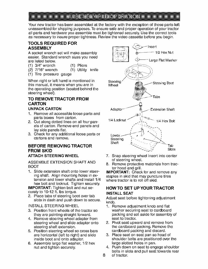
Your new tractor has been assembled at the factory with the exception of those parts leftunassembled for shipping purposes. To ensure safe and proper operation of your tractorall parts and hardware you assemble must be tightened securely. Use the correct toolsas necessary to insure proper tightness. Review the video cassette before you begin.
TOOLS REQUIRED FORASSEMBLY
A socket wrench set will make assemblyeasier. Standard wrench sizes you needare listed below.(1) 3/4" wrench (1) Pliers(2) 7/16"wrench (1) Utility knife(1) Tire pressure gauge
¢_-t Insert
_---_ -- ----_- 1/2 Hex Nut
C-_:;_--_ Large Flat Washer
When right or left hand is mentioned inthis manual, it means when you are inthe operating position (seated behind thesteering wheel).
TO REMOVE TRACTOR FROMCARTONUNPACK CARTON
1. Remove all accessible loose parts andparts boxes from carton.
2. Cut along dotted lines on all four pan-els of carton. Remove end panels andlay side panels flat.
3. Check for any additional loose parts orcartons and remove.
BEFORE REMOVING TRACTORFROM SKIDATTACH STEERING WHEEL
ASSEMBLE EXTENSION SHAFT ANDBOOT1. Slide extension shaft onto lower steer-
ing shaft. Align mounting holes in ex-tension and lower shafts and install 1/4hex bolt and Iocknut. Tighten securely.
IMPORTANT: Tighten bolt and nut se-curely to 10-12 ft. Ibs torque.2. Place Labs of steering boot over tab
slots in dash and push down to secure.
INSTALL STEERING WHEEL3. Position front wheels of the tractor so
they are pointing straight forward.4. Remove steering wheel adapter from
steering wheel and slide adapter ontosteering shaft extension.
5. Position steering wheel so cross barsare horizontal (left to right) and slideinside boot and onto adapter.
6. Assemble large flat washer, 1/2 hexnut and tighten securely.
Wheel g Boot
7. Snap steering wheel insert into centerof steering wheel.
8. Remove protective materials from trac-tor hood and grill.
IMPORTANT: Check for and remove anystaples in skid that may puncture tireswhere tractor is to roll off skid.
HOW TO SET UP YOUR TRACTORINSTALL SEAT
Adjust seat before tightening adjustmentknob.1. Remove adjustment knob and flat
washer securing seat to cardboardpacking and set aside for assembly ofseat to tractor.
2. Pivot seat upward and remove fromthe cardboard packing. Remove thecardboard packing and discard.
3. Place seat on seat pan so head ofshoulder bolts are positioned over thelarge slotted holes in pan.
4. Push down on seat to engage shoulderbolts in slots and pull seat towards rear
8 of tractor.

5. Pivotseat and pan forwardand as-sembleadjustmentknob and flatwasher loosely.Donot tighten.
6. Lowerseat into operatingpositionandsit in seat.
7. Slideseat until a comfortablepositionis reachedwhich allowsyou to pressclutch/brakepedalall the waydown.
8. Getoff seat withoutmoving its ad-justed position.
9. Raiseseat and tightenadjustmentknobsecurely.
Seat
Seat I
\
\
ShoulderBolts
Washer - _'_Flat
Adjustment Knob
CHECK BATTERY
1. Lift seat pan to raised position.NOTE: If this battery is put into serviceafter month and year indicated on label(label located between terminals) chargebattery for minimum of one hour at 6-10amps. (See "BATTERY" in Maintenancesection of this manual for charging instruc-tions).
_rminal
NOTE: You may now roll or drive yourtractor off the skid. Follow the appropriateinstruction below to remove the tractorfrom the skid.
TO ROLL TRACTOR OFF SKID (SeeOperation section for location andfunction of controls)1. Press lift lever plunger and raise
attachment lift lever to its highest po-sition.
2. Release parking brake by depressingclutch/brake pedal.
3. Place gearshift lever in neutral (N)position.
4. Roll tractor forward off skid.5. Remove banding holding deflector
shield up against tractor.TO DRIVE TRACTOR OFF SKID
(See Operation section for locationand function of controls)_il,WARNING: Before starting, read, un-derstand and follow all instructions in theOperation section of this manual. Be suretractor is in a well-ventilated area. Be surethe area in front of tractor is clear of otherpeople and objects.1. Be sure all the above assembly steps
have been completed.2. Check engine oil level and fill fuel tank
with gasoline.3. Sit on seat in operating position,
depress clutch/brake pedal and set theparking brake.
4. Place gear shift lever in neutral (N)position.
5. Press lift lever plunger and raiseattachment lift lever to its highest posi-tion.
6. Start the engine. After engine hasstarted, move throttle control to idleposition.
7. Depress clutch/brake pedal into full"BRAKE" position and hold. Movegearshift lever to 1st gear.
8. Slowly release clutch/brake pedal andslowly drive tractor off skid.
9. Apply brake to stop tractor, set park-ing brake and place gearshift lever inneutral position.
10.Turn ignition key to "STOP" position.Continue with the instructions that follow.
9

INSTALL MULCHER PLATE
(If previously removed)1. Raise and hold deflector shield in
upright position.2. Place front of mulcher plate over front
of mower deck opening and slide intoplace, as shown.
3. Hook front latch into hole on front ofmower deck.
4. Hook rear latch into hole on back ofmower deck.
DeflectorShielc
MulcherPlate
LatchHooks
_CAUTION: Do not remove deflectorshield from mower. Raise and hold shield
when attaching mulcher plate and allow itto rest on plate while in operation.
TO CONVERTTO BAGGING ORDISCHARGING
Simply remove mulcher plate and storein a safe place.Your mower is now readyfor discharging or installation of optionalgrass catcher accessory.NOTE: It is not necessary to changeblades. The mulcher blades are designedfor discharging and bagging also.
CHECKTIRE PRESSUREThe tires on your tractor were overinflatedat the factory for shipping purposes.Correct tire pressure is important for bestcutting performance.• Reduce tire pressure to PSI shown in
"PRODUCT SPECIFICATIONS" sectionof this manual.
CHECK DECK LEVELNESS
For best cutting results, mower hous-ing should be properly leveled. See"TO LEVEL MOWER HOUSING" in theService and Adjustments section of thismanual.
CHECK FOR PROPER POSITION OFALL BELTS
See the figures that are shown for replac-ing motion and mower blade drive beltsin the Service and Adjustments section ofthis manual. Verify that the belts are routedcorrectly.
CHECK BRAKE SYSTEM
After you learn how to operate your tractor,check to see that the brake is properlyadjusted. See "TO ADJUST BRAKE" in theService and Adjustments section of thismanual.
v" CHECKLISTBefore you operate and enjoy your newtractor, we wish to assure that you receivethe best performance and satisfaction fromthis Quality Product.Please review the following checklist:v" All assembly instructions have been
completed.v" No remaining loose parts in carton.J Battery is properly prepared and
charged. (Minimum 1 hour at 6 amps).v" Seat is adjusted comfortably and tight-
ened securely.v" All tires are properly inflated. (For ship-
ping purposes, the tires were overin-flared at the factory).
v" Be sure mower deck is properly leveledside-to-sideifront-to-rear for best cuttingresults. (Tires must be properly inflatedfor leveling).
v" Check mower and drive belts. Be surethey are routed properly around pulleysand inside all belt keepers.
v" Check wiring. See that all connectionsare still secure and wires are properlyclamped.
While learning how to use your tractor, payextra attention to the following importantitems:v" Engine oil is at proper level.J Fuel tank is filled with fresh, clean, regu-
lar unleaded gasoline.v" Become familiar with all controls - their
location and function. Operate thembefore you start the engine.
v" Be sure brake system is in safe oper-ating condition.
10
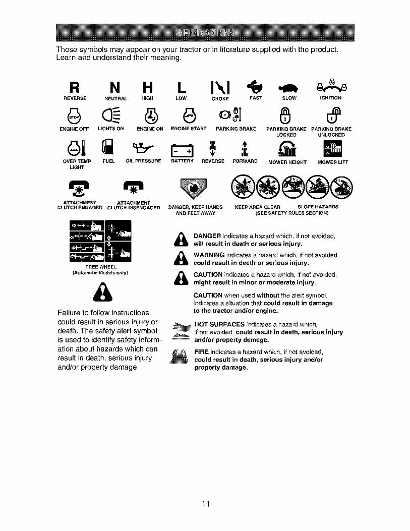
These symbols may appear on your tractor or in literature supplied with the product.Learn and understand their meaning.
R N H L I'.,IREVERSE NEUTRAL HIGH LOW CHOKE FAST SLOW IGNITION
ENGINE OFF LIGHTS ON ENGINE ON ENGINE START PARKING BRAKE PARKING BRAKE PARKING BRAKELOCKED UNLOCKED
OVER TEMP FUEL OIL PRESSURE BATTERY REVERSE FORWARD
LIGHT
ATTACHMENT ATTACHMENTCLUTCH ENGAGED CLUTCH DISENGAGED
FREE WHEEL{Automatic Models only)
MOWER HEIGHT MOWER LIFT
DANGER, KEEP HANDSAND FEET AWAY
KEEP AREA CLEAR SLOPE HAZARDS
(SEE SAFETY RULES SECTION)
&Failure to follow instructions
could result in serious injury or
death. The safety alert symbolis used to identify safety inform-ation about hazards which can
result in death, serious injury
and/or property damage.
&&&
DANGER indicates a hazard which, if not avoided,will result in death or serious injury.
WARNING indicates a hazard which, if not avoided,could result in death or serious injury.
CAUTION indicates a hazard which, if notavoided,might result in minor or moderate injury.
CAUTION when used without the alert symbol,indicates a situation that could result in damageto the tractor and/or engine.
_HOT SURFACES indicates a hazard which,if not avoided, could result in death, serious injuryand/or property damage.
FIRE indicatesa hazard which, if not avoided,could result in death, serious injury and/orproperty damage.
11

KNOW YOUR TRACTOR
READ THIS OWNER'S MANUAL AND SAFETY RULES BEFORE OPERATING YOURTRACTOR
Compare the illustrations with your tractor to familiarize yourself with the locations ofvarious controls and adjustments. Save this manual for future reference.
AttachmentClutch Lever
Light SwitchIgnition Switch Position
Lift LeverAmmeter ...... --. Plunger
ThrottletChoke AttachmentControl Lift Lever
Clutch/BrakePedaI "- ...... "
Heightustment
Indicator
Parking Brake Lever
Gearshift Lever
Our tractors conform to the safety standards of theAmerican National Standards Institute.
AMMETER - Indicates charging (+) ordischarging (-) of battery.ATTACHMENT CLUTCH LEVER - Usedto engage the mower blades, or other at-tachments mounted to your tractor.ATTACHMENT LIFT LEVER - Used toraise, lower, and adjust the mower deck orother attachments mounted to your tractor.CLUTCHtBRAKE PEDAL - Used fordeclutchJng and braking the tractor andstarting the engine.GEARSHIFT LEVER - Selects the speedand direction of tractor.
IGNITION SWITCH - Used for starting andstopping the engine.LIFT LEVER PLUNGER - Used to releaseattachment lift lever when changing itsposition.LIGHT SWITCH POSITION -Turns theheadlights on and off.PARKING BRAKE LEVER - Locks clutch/brake pedal into the brake position.THROTTLE/CHOKE CONTROL - Used
for starting and controlling engine speed.
12

The operation of any tractor can result in foreign objects thrown intothe eyes, which can result in severe eye damage. Always wear safetyglasses or eye shields while operating your tractor or performing anyadjustments or repairs. We recommend a wide vision safety mask overspectacles or standard safety glasses.
HOW TO USE YOURTRACTORTO SET PARKING BRAKE
Your tractor is equipped with an operatorpresence sensing switch. When engineis running, any attempt by the operatorto leave the seat without first setting theparking brake will shut off the engine.1. Depress clutch/brake pedal all the way
down and hold.2. Pull parking brake lever up and release
pressure from clutch/brake pedal.Pedal should remain in brake position.Make sure parking brake will hold trac-tor secure.
Attachment Clutch Lever"En Position
_nition Key
"Disengaged .... Brake"Position Position
STOPPING
MOWER BLADES -
• To stop mower blades, move attachmentclutch lever to disengaged position.
GROUND DRIVE -
• To stop ground drive, depress clutch/brake pedal all the way down.
• Move gearshift lever to neutral (N)position.
ENGINE -
• Move throttle control between half andfull speed (fast) position.
NOTE: Failure to move throttle controlbetween half and full speed (fast) posi-tion, before stopping, may cause engine to"backfire".• Turn ignition key to "STOP" position and
remove key. Always remove key whenleaving tractor to prevent unauthorizeduse.
• Never use choke to stop engine.
IMPORTANT: Leaving the ignition switchin any position other than "STOP" willcause the battery to discharge and godead.NOTE: Under certain conditions whentractor is standing idle with the enginerunning, hot engine exhaust gases maycause "browning" of grass. To eliminatethis possibility, always stop engine when_opping tractor on grass areas.
CAUTION: Always stop tractor com-pletely, as described above, before leavingthe operator's position.
TO USE THROTTLE CONTROL
Always operate engine at full throttle.• Operating engine at less than full
throttle reduces the battery chargingrate.
• Full throttle offers the best bagging andmower performance.
TO MOVE FORWARD AND BACKWARD
The direction and speed of movement iscontrolled by the gearshift lever.1. Start tractor with clutch/brake pedal
depressed and gearshift lever in neutral(N) position.
2. Move gearshift lever to desired po-sition.
3. Slowly release clutch/brake pedal tostart movement.
IMPORTANT: Bring tractor to a completestop before shifting or changing gears.Failure to do so will shorten the useful lifeof your transaxle.
TO ADJUST MOWER CUTTING HEIGHT
The position of the attachment lift leverdetermines the cutting height.• Grasp lift lever.• Press plunger with thumb and move
lever to desired position.The cutting height range is approxi-mately 1-1/2 to 4". The heights are mea-sured from the ground to the blade tip withthe engine not running. These heightsare approximate and may vary dependingupon soil conditions, height of grass andtypes of grass being mowed.
13

• The average lawn should be cut to ap-proximately 2-1/2 inches during the coolseason and to over 3 inches during hotmonths. For healthier and better look-ing lawns, mow often and after moder-ate growth.
• For best cutting performance, grassover 6 inches in height should bemowed twice. Make the first cut rela-tively high; the second to desired height.
TO ADJUST GAUGE WHEELS
Gauge wheels are properly adjustedwhen they are slightly off the ground whenmower is at the desired cutting height inoperating position. Gauge wheels thenkeep the deck in proper position to helpprevent scalping in most terrain conditions.NOTE: Adjust gauge wheels with tractoron a flat level surface.1. Adjust mower to desired cutting height
(See "TO ADJUST MOWER CUTTINGHEIGHT" in this section of manual).
2. With mower in desired height of cutposition, gauge wheels should beassembled so they are slightly off theground. Install gauge wheel in ap-propriate hole with shoulder bolt, 3/8washer, and 3/8-16 Iocknut and tightensecurely.
3. Repeat for opposite side, installinggauge wheel in same adjustment hole.
Gauge Wheel o_%Mounting \ ._f_-_ _
Locknut _'[41_ Y "_ _/ Shoulder
WasherGauge Wheel
TO OPERATE MOWER
Your tractor is equipped with an operatorpresence sensing switch. Any attemptby the operator to leave the seat with theengine running and the attachment clutchengaged will shut off the engine.1. Select desired height of cut.2. Start mower blades by engaging at-
tachment clutch control.TO STOP MOWER BLADES -_sengage attachment clutch control.
CAUTION: Do not operate the mowerwithout either the entire grass catcher,on mowers so equipped, or the deflectorshield in place.
AttachmentClutch Lever Attachernnt"Engaged" ghPosition Position
"Disengaged"Position
LowPosition
Shield
TO OPERATE ON HILLS
_,WARNING: Do not drive up or downhills with slopes greater than 15 ° and donot drive across any slope. Use the slopeguide at the back of this manual.• Choose the slowest speed before start-
ing up or down hills.• Avoid stopping or changing speed on
hills.• If slowing is necessary, move throttle
control lever to slower position.• If stopping is absolutely necessary, push
clutch/brake pedal quickly to brake posi-tion and engage parking brake.
• Move gearshift lever to 1st gear. Besure you have allowed room for tractorto roll slightly as you restart movement.
• To restart movement, slowly releaseparking brake and clutch/brake pedal.
• Make all turns slowly.
TO TRANSPORT
• Raise attachment lift to highest positionwith attachment lift control.
• When pushing or towing your tractor,be sure gearshift lever is in neutral (N)position.
• De not push or tow tractor at more thanfive (5) MPH.
NOTE: To protect hood from damagewhen transporting your tractor on a truckor a trailer, be sure hood is closed andsecured to tractor. Use an appropriatemeans of tying hood to tractor (rope, cord,etc.).
TOWING CARTS AND OTHER ATTACH-MENTS
Tow only the attachments that are recom-mended by and comply with specificationsof the manufacturer of your tractor. Usecommon sense when towing. Toe heavyof a load, while on a slope, is dangerous.Tires can lose traction with the ground andcause you to lose control of your tractor.
14

BEFORE STARTING THE ENGINECHECK ENGINE OIL LEVEL
The engine in your tractor has beenshipped, from the factory, already filledwith summer weight oil.1. Check engine oil with tractor on level
ground.2. Unthread and remove oil fill cap/
dipstick; wipe oil off. Reinsert thedipstick into the tube and rest oil fillcap on the tube. Do not thread the caponto the tube. Remove and read oillevel. If necessary, add oil until "FULl"mark on dipstick is reached. Do notoverfill.
° For cold weather operation you shouldchange oil for easier starting (See theoil viscosity chart in the Maintenancesection of this manual).
° To change engine oil, see the Mainte-nance section in this manual.
ADD GASOLINE
• Fill fuel tank to bottom of filler neck. Donot overfill. Use fresh, clean, regularunleaded gasoline with a minimum of87 octane. (Use of leaded gasoline willincrease carbon and lead oxide depositsand reduce valve life). Do not mix oilwith gasoline. Purchase fuel in quan-tities that can be used within 30 days toassure fuel freshness.
Ai:_CAUTION: Wipe off any spilled oil orfuel. Do not store, spill or use gasolinenear an open flame.IMPORTANT: When operating in temper-atures below32°F(0°C), use fresh, cleanwinter grade gasoline to help insure goodcold weather starting.
CAUTION: Alcohol blended fuels (calledgasohol or using ethanol or methanol) canattract moisture which leads to separa-tion and formation of acids during storage.Acidic gas can damage the fuel systemof an engine while in storage. To avoidengine problems, the fuel system shouldbe emptied before storage of 30 daysor longer. Drain the gas tank, start theengine and let it run until the fuel linesand carburetor are empty. Use fresh fuelnext season. See Storage Instructions foradditional information. Never use engineor carburetor cleaner products in the fueltank or permanent damage may occur.
TO START ENGINE
When starting the engine for the first timeor if the engine has run out of fuel, it willtake extra cranking time to move fuel fromthe tank to the engine.1. Sit on seat in operating position,
depress clutchtorake pedal and setparking brake.
2. Place gear shift lever in neutral (N)position.
3. Move attachment clutch to disengagedposition.
4. Move throttle control to choke position.NOTE: Before starting, read the warmand cold starting procedures below.5. Insert key into ignition and turn key
clockwise to start position and releasekey as soon as engine starts. Donot run starter continuously for morethan fifteen seconds per minute. If theengine does not start after severalattempts, move throttle control to fastposition, wait a few minutes and tryagain. If engine still does not start,move the throttle control back to thechoke position and retry.
WARM WEATHER STARTING (50 ° F andabove)
6. When engine starts, move the throttlecontrol to the fast position.
• The attachments and ground drive cannow be used. If the engine does notaccept the load, restart the engine andallow it to warm up for one minute usingthe choke as described above.
COLD WEATHER STARTING ( 50 ° F andbelow)6. When engine starts, leave throttle
control in choke position until enginewarms up and begins to run roughly.Once rough running begins, imme-diately move the throttle control to thefast position. Engine warm-up maytake from several seconds to severalminutes (the colder the temperature,the longer the warm-up).
* The attachments can also be used dur-ing the engine warm-up period.
NOTE: If at a high altitude (above 3000feet) or in cold temperatures (below 32 F)the carburetor fuel mixture may need tobe adjusted for best engine performance(see "TO ADJUST CARBURETOR" in theService and Adjustments section of thismanual).
15

MOWING TIPS
• Mower should be properly leveled forbest mowing performance. See "TOLEVEL MOWER HOUSING" in theService and Adjustments section of thismanual.
• The left hand side of mower should beused for trimming.
• Drive so that clippings are dischargedonto the area that has already beencut. Have the cut area to the right ofthe tractor. This will result in a moreeven distribution of clippings and moreuniform cutting.
• When mowing large areas, start byturning to the right so that clippings willdischarge away from shrubs, fences,driveways, etc. After one or two rounds,mow in the opposite direction makingleft hand turns until finished.
1
MULCHING MOWING TIPS
IMPORTANT: For best performance, keepmower housing free of built-up grass andtrash. Clean after each use.• The special mulching blade will recut
the grass clippings many times andreduce them in size so that as they fallonto the lawn they will disperse intothe grass and not be noticed. Also, themulched grass will biodegrade quicklyto provide nutrients for the lawn. Alwaysmulch with your highest engine (blade)speed as this will provide the best recut-ring action of the blades.
• Avoid cutting your lawn when it is wet.Wet grass tends to form clumps andinterferes with the mulching action. Thebest time to mow your lawn is the earlyafternoon. At this time the grass hasdried, the newly cut area will not beexposed to direct sunlight.
• For best results, adjust the mowercutting height so that the mower cutsoff only the top one-third of the grassblades. For extremely heavy grass, re-duce your width of cut on each pass andmow slowly.
• If grass is extremely tall, it should bemowed twice to reduce load and pos-sible fire hazard from dried clippings.Make first cut relatively high; the secondto the desired height.
• Do not mow grass when it is wet.Wet grass will plug mower and leaveundesirable clumps. Allow grass to drybefore mowing.
• Always operate engine at full throttlewhen mowing to assure better mowingperformance and proper discharge ofmaterial. Regulate ground speed byselecting a low enough gear to give themower cutting performance as well asthe quality of cut desired.
• When operating attachments, select aground speed that will suit the terrainand give best performance of the at-tachment being used.
MAX 1/3
• Certain types of grass and grassconditions may require that an area bemulched a second time to completelyhide the clippings. When doing a sec-ond cut, mow across (perpendicular) tothe first cut path.
• Change your cutting pattern from weekto week. Mow north to south one weekthen change to east to west the nextweek. This will help prevent matting andgraining of the lawn.
16

FILL IN DATESAsYooCO PLETEREGULAR SERVICE _%q_F- SERVICE_j_,_-_r_ .... DATES
Check Br_ke OperationCheck Tire Pressure _
Check Operator Presence andT Interlock Systems
R Check for Loose Fasteners _ _5
Sharpen/Replace Mower Blades _,_T Lubrication Chad"
0 Check B_ttery Level
R Clean Batteryand Terminals _Check Trans_le Cooling
Check V-Belt_
Check Engine Oil Level _
Change Engine Oil (with oil tilter) _1,2
E Change Engine Oil (without oil filter) _1,_
N Clean Air Filter _
G Clean Air Screen _2
Inspect Muffler/Spark Attester
E Replace Oil Filter (It equipped) _
Clean Engine Cooling Fins I_
Replace Spark Plug _
Replace Air Filter Paper Cartridge _z
Replace Fuel Fiffer
1 ChAnge more often when operating under a hoaV_' ICed or]r_ high _mbieot tornper_.ttore_
2 _er_]_ more often wher_ ope_tir_g in di_ or du_y ¢or_dition_.
3 R_pla_ blades morn3 oflen when mowing in _tndy soil.4 • Not required if equipped with rn_iotenance ¸tree b_ttery.5 • Tighten front axle pivot bolt to 35 ft. Ibm.rn_xirnum.
DO not _rtighten
GENERAL RECOMMENDATIONSThe warranty on this tractor does notcover items that have been subjected tooperator abuse or negligence. To receivefull value from the warranty, operatormust maintain tractor as instructed in thismanual.Some adjustments will need to be madeperiodically to properly maintain yourtractor.At least once a season, check to see ifyou should make any of the adjustmentsdescribed in the Service and Adjustmentssection of this manual.• At least once a year you should replace
the spark plug, clean or replace air filter,and check blades and belts for wear.A new spark plug and clean air filterassure proper air-fuel mixture and helpyour engine run better and last longer.
BEFORE EACH USE1. Check engine oil level.2. Check brake operation.3. Check tire pressure.4. Check operator presence and
interlock systems for proper operation.5. Check for loose fasteners.
LUBRICATION CHART
@ Spindle (_ SpindleZerk _ Zerk
I
@Front Wheel q @Front WheelBearing Bearing ZerkZerk
®En
_ -_ shift..... Pivots
@SAE 30 or 10w30 MOTOR OIL@GENERAL PURPOSE GREASE(#)REFER TO Maintenance "ENGINE _SECTION
IMPORTANT: Do not oil or grease thepivot points which have special nylonbearings. Viscous lubricants will attractdust and dirt that will shorten the life of theself-lubricating bearings. If you feel theymust be lubricated, use only a dry, pow-dered graphite type lubricant sparingly.
17

TRACTORAlways observe safety rules when per-forming any maintenance.BRAKE OPERATION
If tractor requires more than six (6) feetstopping distance at high speed Jn highestgear, then brake must be adjusted. (See"TO ADJUST BRAKE" in the Service andAdjustments section of this manual).TIRES
• Maintain proper air pressure in all tires(See "PRODUCT SPECIFICATIONS"section of this manual).
• Keep tires free of gasoline, oil, or insectcontrol chemicals which can harm rub-ber.
• Avoid stumps, stones, deep ruts, sharpobjects and other hazards that maycause tire damage.
NOTE: To seal tire punctures and preventflat tires due to slow leaks, tire sealantmay be purchased from your local partsdealer. Tire sealant also prevents tire dryrot and corrosion.OPERATOR PRESENCE SYSTEM
Be sure operator presence and interlocksystems are working properly. If your trac-tor does not function as described, repairthe problem immediately.• The engine should not start unless the
clutch/brake pedal is fully depressedand attachement clutch control is in thedisengaged position.
• When the engine is running, any at-tempt by the operator to leave the seatwithout first setting the parking brakeshould shut off the engine.
• When the engine is running and theattachment clutch is engaged, any at-tempt by the operator to leave the seatshould shut off the engine.
• The attachment clutch should never op-erate unless the operator is in the seat.
BLADE CAREFor best results mower blades must bekept sharp. Replace bent or damagedblades.
BLADE REMOVAL
1. Raise mower to highest position to al-low access to blades.
2. Remove blade bolt, lock washer andflat washer securing blade.
3. Install new or resharpened bladewith trailing edge up towards deck asshown.
IMPORTANT: To ensure proper assembly,center hole in blade must align with staron mandrel assembly.4. Reassemble blade bolt, lock washer
and flat washer in exact order asshown.
5. Tighten blade bolt securely (27-35 Ft.Lbs. torque).
IMPORTANT: Blade bolt is heat treated.If bolt needs replacing, replace only withapprove bolt shown in the Repair Parts.
Trailir ge Up Mandrel Assembly
Lock
TO SHARPEN BLADE
NOTE: We do not recommend sharp-ening blade - but if you do, be sure theblade is balanced.Care should be taken to keep the bladebalanced. An unbalanced blade will causeexcessive vibration and eventual damageto mower and engine.• The blade can be sharpened with a file
or on a grinding wheel. Do not attemptto sharpen while on the mower.
• To check blade balance, you will need a5/8" diameter steel bolt, pin, or a conebalancer. (When using a cone balancer,follow the instructions supplied withbalancer.)
NOTE: Do not use a nail for balancingblade. The lobes of the center hole mayappear to be centered, but are not.• Slide blade on to an unthreaded portion
of the steel bolt or pin and hold thebolt or pin parallel with the ground. Ifblade is balanced, it should remain in ahorizontal position. If either end of theblade moves downward, sharpen theheavy end until the blade is balanced.
5/8 _ Bolt orPin
Center Hole
18

BATTERY
Your tractor has a battery charging systemwhich is sufficient for normal use. How-ever, periodic charging of the battery withan automotive charger will extend its life.• Keep battery and terminals clean.• Keep battery bolts tight.• Keep small vent holes open.• Recharge at 6-10 amperes for 1 hour.NOTE: The original equipment battery onyour tractor is maintenance free. Do notattempt to open or remove caps or covers.Adding or checking level of electrolyte isnot necessary.
TO CLEAN BATTERY AND TERMINALS
Corrosion and dirt on the battery andterminals can cause the battery to "leak"power.1. Disconnect BLACK battery cable first
then RED battery cable and removebattery from tractor.
2. Rinse the battery with plain water anddry.
3. Clean terminals and battery cable endswith wire brush until bright.
4. Coat terminals with grease or petro-leum jelly.
5. Reinstall battery (See "REPLACINGBATTERY" in the SERVICE AND AD-
JUSTMENTS section of this manual).
TRANSAXLE COOLING
Keep transaxle free from build-up of dirtand chaff which can restrict cooling.
V-BELTSCheck V-belts for deterioration and wearafter 100 hours of operation and replaceif necessary. The belts are not adjustable.Replace belts if they begin to slip fromwear.
ENGINELUBRICATION
Only use high quality detergent oil ratedwith API service classification SF-SJ. Se-
lect the oil's SAE viscosity grade accord-ing to your expected operating tempera-ture.
Change the oil after every 50 hours of op-eration or at least once a year if the tractoris not used for 50 hours in one year.Check the crankcase oil level before start-
ing the engine and after each eight (8)hours of operation.
TO CHANGE ENGINE OIL
Determine temperature range expectedbefore oil change. All oil must meet APIservice classification SF-SJ.• Be sure tractor is on level surface.• Oil will drain more freely when warm.• Catch oil in a suitable container.1. Remove oil fill cap/dipstick. Be careful
not to allow dirt to enter the enginewhen changing oil.
2. Remove yellow cap from end of drainvalve and install the drain tube onto the
fitting.Oil Drain Valve
Closed and
Locked Position -Ia
Yellow Cap ---._
3. Unlock drain valve by pushing inwardslightly and turning counterclockwise.
4. To open, pull out on the drain valve.5. After oil has drained completely, close
and lock the drain valve by pushinginward and turning clockwise until thepin is in the locked position as shown.
6. Remove the drain tube and replace thecap onto to the end of the drain valve.
7. Refill engine with oil through oil fill dip-stick tube. Pour slowly. Do not overfill.For approximate capacity see "PROD-UCT SPECIFICATIONS" section of thismanual.
8. Use gauge on oil fill cap/dipstick forchecking level. Be sure dipstick cap istightened securely for accurate read-ing. Keep oil at "FULL' line on dipstick.
AIR FILTER
Your engine will not run properly using adirty air filter. Clean the foam pre-cleanerafter every 25 hours of operation or everyseason. Service paper cartridge every100 hours of operation or every season,whichever occurs first.Service air cleaner more often under dustyconditions.1. Remove knob and cover.
19

2. Remove wing nut and air cleaner frombase.
TO SERVICE PRE-CLEANER
3. Slide foam pre-cleaner off cartridge.4. Wash it in liquid detergent and water.5. Squeeze it dry in a clean cloth. Allow it
to dry.6. Saturate it in engine oil. Wrap it in
clean, absorbent cloth and squeeze toremove excess oil.
TO SERVICE CARTRIDGE
1. Replace a dirty, bent, or damagedcartridge.
NOTE: Do not wash the paper cartridgeor use pressurized air, as this will damagethe cartridge.2. Reinstall the pre-cleaner (cleaned and
oiled) over the paper cartridge.3. Reassemble air cleaner, wing nut,
cover and tighten knob securely.
Air Cleaner Cover Knob
Foam Pre- NutCleaner,
--RubberGrommet
Air
PaperCartridge
3ieanerBase
Fill Cap/Dipstick
CLEAN AIR SCREEN
Air screen must be kept free of dirt andchaff to prevent engine damage fromoverheating. Clean with a wire brush orcompressed air to remove dirt and stub-born dried gum fibers.
CLEAN AIR INTAKE/COOLING AREAS
To insure proper cooling, make sure thegrass screen, cooling fins, and other exter-nal surfaces of the engine are kept cleanat all times.Every 100 hours of operation (more oftenunder extremely dusty, dirty conditions),remove the blower housing and other cool-ing shrouds. Clean the cooling fins andexternal surfaces as necessary. Make surethe cooling shrouds are reinstalled.
NOTE: Operating the engine with ablocked grass screen, dirty or pluggedcooling fins, and/or cooling shroudsremoved will cause engine damage due tooverheating.ENGINE OIL FILTER
Replace the engine oil filter every seasonor every other oil change if the tractor isused more than 100 hours in one year.
MUFFLER
Inspect and replace corroded muffler andspark arrester (if equipped) as it could cre-ate a fire hazard and/or damage.SPARK PLUG(S)Replace spark plug(s) at the beginningof each mowing season or after every100 hours of operation, whichever occursfirst. Spark plug type and gap setting areshown in "PRODUCT SPECIFICATIONS"section of this manual.
IN-LINE FUEL FILTER
The fuel filter should be replaced onceeach season. If fuel filter becomes
clogged, obstructing fuel flow to carbu-retor, replacement is required.1. With engine cool, remove filter and
plug fuel line sections.2. Place new fuel filter in position in fuel
line with arrow pointing towards carbu-retor.
3. Be sure there are no fuel line leaks and
clamps are properly positioned.4. Immediately wipe up any spilled gaso-
line.
CLEANING
• Clean engine, battery, seat, finish, etc.of all foreign matter.
• Keep finished surfaces and wheels freeof all gasoline, oil, etc.
• Protect painted surfaces with auto-motive type wax.
We do not recommend using a gardenhose or pressure washer to clean yourtractor unless the engine and transmis-sion are covered to keep water out. Waterin engine or transmission will shorten theuseful life of your tractor. Use compressedair or a leaf blower to remove grass,leaves and trash from tractor and mower.
2O

_IL WARNING: TO AVOID SERIOUS INJURY, BEFORE PERFORMING ANY SER-VICE OR ADJUSTMENTS:
1. Depress clutch/brake pedal fully and set parking brake.2. Place gearshift lever Jn neutral (N) position.3. Place attachment clutch Jn "DISENGAGED" position.4. Turn ignition key to "STOP" and remove key.5. Make sure the blades and all moving parts have completely stopped.6. Disconnect spark plug wire from spark plug and place wire where it cannot
come in contact with plug.
TRACTORTO REMOVE MOWERMower will be easier to remove from theright side of tractor.1. Place attachment clutch in "DISEN-
GAGED" position.2. Move attachment lift lever forward to
lower mower to its lowest position.3. Roll belt off engine pulley.4. Remove small retainer spring, and
remove clutch spring off pulley bolt.5. Remove large retainer spring, slide
collar off and push housing guide outof bracket.
6. Disconnect anti-sway bar from chassisbracket by removing retainer spring.
7. Disconnect suspension arms from reardeck brackets by removing retainersprings.
8. Disconnect front links from deck byremoving retainer springs.
9. Raise lift lever to raise suspensionarms. Slide mower out from under trac-tor.
IMPORTANT: If an attachment other thanthe mower deck is to be mounted on thetractor, remove the front links and hookthe clutch spring Into square hole in frame.TO INSTALL MOWER
1. Raise attachment lift lever to its highestposition.
2. Slide mower under tractor with deflec-tor shield to right side of tractor.
3. Lower lift lever to its lowest position.4. Connect front links to mower deck and
secure with retainer springs.5. Connect suspension arms to rear
deck brackets and secure with retainer
springs.6. Connect anti-sway bar to chassis
bracket and secure with retainer spring.
Small Retainer Spring
Clutch 5
Small Retainer
Clutch
RetainerSpring
Anti-SwayBar
prings(Both Sides)
HousingGuide Large Retainer
Spring
21

7. Push clutch cable housing guide intobracket, slide collar onto guide andsecure with large retainer spring.
8. Place flat washer and clutch spring onidler pulley bolt and secure with smallretainer spring.
9. Install belt onto engine pulley.
TO LEVEL MOWER HOUSING
Adjust the mower while tractor is parkedon level ground or driveway. Make suretires are properly inflated (See "PROD-UCT SPECIFICATIONS" section of thismanual). If tires are over or underinflated,you will not properly adjust your mower.
SIDE-TO-SIDE ADJUSTMENT• Raise mower to its highest position.• At the midpoint of both sides of mower,
measure height from bottom edge ofmower to ground. Distance "A" on bothsides of mower should be the same orwithin 1/4" of each other.
• If adjustment is necessary, make adjust-ment on one side of mower only.
• To raise one side of mower, tighten liftlink adjustment nut on that side.
• To lower one side of mower, loosen liftlink adjustment nut on that side.
NOTE: Each full turn of adjustment nutwill change mower height about 1/8".• Recheck measurements after adjusting.
Bottom edge Bottom edge of
Check adjustment on right side of trac-tor. Measure distance "D" directly in frontand behind the mandrel at bottom edge ofmower housing as shown.• Before making any necessary adjust-
ments, check that both front links areequal in length.
• If links are not equal in length, adjustone link to same length as other link.
• To lower front of mower loosen nut "E"on both front links an equal number ofturns.
• When distance "D" is 1/8" to 1/2"lower at front than rear, tighten nuts "F"against trunnion on both front links.
• To raise front of mower, loosen nut "F"from trunnion on both front links. Tightennut "E" on both front links an equal num-ber of turns. The two front links mustremain equal in length.
• When distance "D" is 1/8" to 1/2" lowerat front than rear, tighten nut "F" againsttrunnion on both front links.
• Recheck side-to-side adjustment.
Both Front Links Should be EquaI in Length
__ Arm
Lift Link _--Adjustment Nut
FRONT-TO-BACK ADJUSTMENTIMPORTANT: Deck must be level side-toside. If the following front-to-back adjust-ment is necessary, be sure to adjust bothfront links equally so mower will stay levelside-to-side.To obtain the best cutting results, themower housing should be adjusted sothat the front is approximately 1/8" to 1/2"lower than the rear when the mower is inits highest position.
Front Links
22

TO REPLACE MOWER BLADE DRIVEBELT
The mower blade drive belt may be re-placed without tools. Park the tractor onlevel surface. Engage parking brake.
BELT REMOVAL -
1. Remove mower from tractor (See "TOREMOVE MOWER" in this section ofmanual).
2. Work belt off both mandrel pulleys andidler pulleys.
3. Pull belt away from mower.
BELT INSTALLATION -
1. Work belt around both mandrel pulleysand idler pulleys
2. Make sure belt is in all pulley groovesand inside all belt guides.
3. Install mower (See "To Install Mower" inthis section of this manual).
Mandrel
Mandrel /
Pulley
TO CHECK AND ADJUST BRAKE
Your tractor is equipped with an adjustablebrake system which is mounted on theright side of the transaxle.If tractor requires more than five (5) feet tostop at highest speed in highest gear on alevel, dry concrete or paved surface, thenbrake must be checked and adjusted.
TO CHECK BRAKE
1. Park tractor on a level, dry concrete orpaved surface, depress clutch/brakepedal all the way down and engageparking brake.
2. Place gear shift lever in neutral (N)position.
The rear wheels must lock and skid whenyou try to manually push the tractor for-ward. If the rear wheels rotate, the brakeneeds to be adjusted or the pads need tobe replaced.
TO ADJUST BRAKE
1. Depress clutch/brake pedal all the waydown and engage parking brake.
2. Measure distance between brake oper-ating arm and nut 'W' on brake rod.
3. If distance is other than 1-1/2", loosenjam nut and turn nut 'W' until distancebecomes 1-1/2". Retighten jam nutagainst nut "A".
4. Road test tractor for proper stoppingdistance as stated above. Readjustif necessary. If stopping distance isstill greater than five (5) feet in highestgear, further maintenance is neces-sary. Replace brake pads or contact aSears or other qualified service center.
With Parking Brake "Engaged"
"_ Nut "A_
3 Nut
_OperatingAim
TO REPLACE MOTION DRIVE BELT
Park the tractor on level surface. Engageparking brake. For assistance, there is abelt installation guide decal on bottom sideof left footrest.
BELT REMOVAL -
1. Remove mower (See ''TO REMOVEMOWER" in this section of manual).
NOTE: Observe entire motion drive beltand position of all belt guides and keepers.2. Remove belt from stationary idler and
clutching idler.3. Remove belt downward from around
engine pulley.4. Pull belt slack toward rear of tractor.
Remove belt upwards from transaxlepulley by deflecting belt keepers.
5. Remove belt from center span keeperand pull belt away from tractor.
BELT INSTALLATION -
1. Carefully work new belt down betweentransaxle belt keepers and onto theinput pulley.
2. Slide belt into the center span keeper.
23

3. Pull belt toward front of tractor and rollaround the top groove of engine pulley.
4. Install belt through stationary idler andclutching idler.
5. Make sure belt is in all pulley groovesand inside all belt guides and keepers.
6. Install mower (See "TO INSTALLMOWER" in this section of manual).
Pulley
Clutchi[lIdler
Stationa_Idler
Center Span ....Keeper
Pulley
TRANSAXLE GEAR SHIFT LEVER NEU-TRAL ADJUSTMENT
The transaxle should be in neutral whenthe gear shift lever is in neutral (N) (lockgate) position. The adjustment is presetat the factory; however, if adjustment isneeded, proceed as follows:1. Make sure transaxle is in neutral (N).NOTE: When the tractor rear wheels movefreely, the transaxle is in neutral.2. Loosen adjustment bolt in front of the
right rear wheel.3. Position the gear shift lever in the neu-
tral (N) position.4. Tighten adjustment bolt securely.NOTE: If additional clearance is neededto get to adjustment bolt, move mowerdeck height to the lowest position.
Gearshift Lever Neutral Lock Gate
Adjustment Bolt
TO ADJUST STEERING WHEEL ALIGN-MENT
If steering wheel crossbars are nothorizontal (left to right) when wheels arepositioned straight forward, remove steer-ing wheel and reassemble with crossbarshorizontal. Tighten securely.
FRONT WHEEL TOE-INtCAMBERThe front wheel toe-in and camber are notadjustable on your tractor. If damage hasoccurred to affect the front wheel toe-in orcamber, contact a Sears or other qualifiedservice center.
TO REMOVE WHEEL FOR REPAIRS
1. Block up axle securely.2. Remove axle cover, retaining ring and
washers to allow wheel removal (rearwheels have a square key - Do notlose).
3. Repair tire and reassemble.NOTE: On rear wheels only: aligngrooves in rear wheel hub and axle. Insertsquare key.4. Replace washers and snap retaining
ring securely in axle groove.5. Replace axle cover.NOTE: To seal tire punctures and preventflat tires due to slow leaks, purchase anduse tire sealant from Sears. Tire sealantalso prevents tire dry rot and corrosion.
Washers
RetainingRin
AxleCover
I
Square Key(RearWheel Only)
TO START ENGINE WITH AWEAK BAT-TERY
,_WARNING: Lead-acid batteries gen-erate explosive gases. Keep sparks, flameand smoking materials away from bat-teries. Always wear eye protection whenaround batteries.If your battery is too weak to start theengine, it should be recharged. (See "BAT-TERY" in the MAINTENANCE section ofthis manual).If '1umper cables" are used for emergencystarting, follow this procedure:IMPORTANT: Your tractor is equippedwith a 12 volt system. The other vehiclemust also be a 12 volt system. Do not useyour tractor battery to start other vehicles.
24

TO ATTACH JUMPER CABLES -1. Connect one end of the RED cable
to the POSITIVE (+) terminal of eachbattery(A-B), taking care not to shortagainst tractor chassis.
2. Connect one end of the BLACK cableto the NEGATIVE (-) terminal (C) offully charged battery.
3. Connect the other end of the BLACKcable (D) to good chassis ground,away from fuel tank and battery.
TO REMOVE CABLES, REVERSEORDER -1. BLACK cable first from chassis and
then from the fully charged battery.2. RED cable last from both batteries.
Weak or Dead Fully ChargedBattery Battery
REPLACING BATTERY_IILWARNING: Do not short battery ter-minals by allowing a wrench or any otherobject to contact both terminals at the sametime. Before connecting battery, removemetal bracelets, wristwatch bands, rings,etc.Positive terminal must be connected first toprevent sparking from accidental grounding.1. Lift seat pan to raised position.2. Disconnect BLACK battery cable first
then RED battery cable and carefullyremove battery from tractor.
3. Install new battery with terminals insame position as old battery.
4. First connect RED battery cable topositive (+) terminal with hex bolt andkeps nut as shown. Tighten securely.Slide terminal cover over terminal
5. Connect BLACK grounding cable tonegative (-) terminal with remaininghex bolt and keps nut. Tighten securely.
Terminal Cover Keps Nut
HexBolt
(Red)Cable Negative (Black)
Cable
TO REPLACE HEADLIGHT BULB
1. Raise hood.2. Pull bulb holder out of the hole in the
backside of the grill.3. Replace bulb in holder and push bulb
holder securely back into the hole inthe backside of the grill.
4. Close hood.INTERLOCKS AND RELAYS
Loose or damaged wiring may causeyour tractor to run poorly, stop running, orprevent it from starting.. Check wiring. See electrical wiring
diagram in the Repair Parts section.TO REPLACE FUSE
Replace with 20 amp automotive-typeplug-in fuse. The fuse holder is locatedbehind the dash.
TO REMOVE HOOD AND GRILL AS-SEMBLY
1. Raise hood.2. Unsnap headlight wire connector.3. Stand in front of tractor. Grasp hood at
sides, tilt toward engine and lift off oftractor.
4. When replacing hood, be sure to re-connect the headlight wire connector.
Headlight WireConnector
Seat
25

ENGINE
Maintenance, repair, or replacement ofthe emission control devices and systems,which are being done at the customers ex-pense, may be performed by any non-roadengine repair establishment or individual.Warranty repairs must be performed by anauthorized engine manufacturer's serviceoutlet.TO ADJUSTTHROTTLE CONTROLCABLE
The throttle control has been preset at thefactory and adjustment should not be nec-essary. Check adjustment as describedbelow before loosening cable. If adjust-ment is necessary, proceed as follows:1. With engine not running, move throttle
control lever from slow to choke posi-tion. Slowly move lever from choke tofast position.
2. Check to see if hole in throttle leverand hole in speed control bracket arealigned.
3. If holes are not aligned, loosen cableclamp screw and align the holes byinserting a pencil or a 1/4" drill bitthrough both holes.
4. Pull throttle cable up to remove slackand tighten cable clamp screw. Re-move alignment pencil or drill bit.
TO ADJUST CARBURETOR
The carburetor has been preset at thefactory and adjustment should not be nec-essary. However, minor adjustment maybe required to compensate for differencesin fuel, temperature, altitude or load. If thecarburetor does need adjustment, proceedas follows:In general, turning the adjusting needles in(clockwise) decreases the supply of fuel tothe engine giving a leaner fuel/air mixture.Turning the adjusting needles out (counter-clockwise) increases the supply of fuel tothe engine giving a richer fuel/air mixture.IMPORTANT: Damage to the needles andseats in carburetor may result if turned intoo tight.NOTE: The carburetor on this engine islow emission. It is equipped with an idlefuel adjusting needle with a limiter cap,which allows some adjustment within thelimits allowed by the cap. Do not attemptto remove the limiter cap. The limiter capcannot be removed without breaking theadjusting needle.1. Be sure you have a clean air filter and
the throttle control cable is adjustedproperly (see above).
2. Start engine and allow to warm for fiveminutes. Make adjustments with enginerunning and shift/motion control leverin neutral (N) position.
3. Idle speed setting - With throttle controllever in slow position, engine shouldidle at 1750 RPM. If engine idles tooslow or fast, turn idle speed adjustingscrew in or out until correct idle is at-tained.
4. Idle fuel needle setting - With throttlecontrol lever in slow position, turn idlefuel adjustment needle in (clockwise)until engine begins to die and then turnout (counterclockwise) until engineruns rough. Turn needle to a pointmidway between those two positions.
5. Recheck idle speed. Readjust if nec-essary.
ACCELERATION TEST -6. Move throttle control lever from slow
to fast position. If engine hesitates ordies, turn idle fuel adjusting needle out(counterclockwise) 1/8 turn. Repeattest and continue to adjust, if neces-sary, until engine accelerates smoothly.
High speed stop is factory adjusted. Donot adjust - damage may result.IMPORTANT: Never tamper with theengine governor, which is factory setfor proper engine speed. Overspeed-ing the engine above the factory highspeed setting can be dangerous. If youthink the engine-governed high speedneeds adjusting, contact a Sears or otherqualified service center, which has properequipment and experience to make anynecessary adjustments.
CableClamp __
Screw _[_-_Speed Co_rol _._.t:_;'LJBracket _lff_7" I
vet
Idle Speed
26

Immediately prepare your tractor for stor-age at the end of the season or if the trac-tor will not be used for 30 days or more._WARNING: Never store the tractor
with gasoline in the tank inside a buildingwhere fumes may reach an open flameor spark. Allow the engine to cool beforestoring in any enclosure.
TRACTORRemove mower from tractor for winterstorage. When mower is to be stored for aperiod of time, clean it thoroughly, removeall dirt, grease, leaves, etc. Store in aclean, dry area.1. Clean entire tractor (See "CLEANING"
in the Maintenance section of thismanual).
2. Inspect and replace belts, if necessary(See belt replacement instructions inthe Service and Adjustments section ofthis manual).
3. Lubricate as shown in the Maintenancesection of this manual.
4. Be sure that all nuts, bolts and screwsare securely fastened. Inspect movingparts for damage, breakage and wear.Replace if necessary.
5. Touch up all rusted or chipped paintsurfaces; sand lightly before painting.
BATTERY• Fully charge the battery for storage.• After a period of time in storage, battery
may require recharging.• To help prevent corrosion and power
leakage during long periods of storage,battery cables should be disconnectedand battery cleaned thoroughly (see "TOCLEAN BATTERY AND TERMINALS" inthe Maintenance section of this manual).
• After cleaning, leave cables discon-nected and place cables where theycannot come in contact with batteryterminals.
• If battery is removed from tractor forstorage, do not store battery directly onconcrete or damp surfaces.
ENGINEFUEL SYSTEM
IMPORTANT: It is important to preventgum deposits from forming in essentialfuel system parts such as carburetor, fuelhose, or tank during storage. Also, alcohol
blended fuels (called gasohol or usingethanol or methanol) can attract moisturewhich leads to separation and formation ofacids during storage. Acidic gas can dam-age the fuel system of an engine while instorage.• Empty the fuel tank by starting the en-
gine and letting it run until the fuel linesand carburetor are empty.
• Never use engine or carburetor cleanerproducts in the fuel tank or permanentdamage may occur.
• Use fresh fuel next season.NOTE: Fuel stabilizer is an acceptable
alternative in minimizing the formationof fuel gum deposits during storage.Add stabilizer to gasoline in fuel tankor storage container. Always follow themix ratio found on stabilizer container.
Run engine at least 10 minutes afteradding stabilizer to allow the stabilizerto reach the carburetor. Do not emptythe gas tank and carburetor if usingfuel stabilizer.
ENGINE OIL
Drain oil (with engine warm) and replacewith clean engine oil. (See "ENGINE" inthe Maintenance section of this manual).CYLINDER(S)1. Remove spark plug(s).2. Pour one ounce of oil through spark
plug hole(s) into cylinder(s).3. Turn ignition key to start position for a
few seconds to distribute oil.4. Replace with new spark plug(s).
OTHER
• Do not store gasoline from one seasonto another.
• Replace your gasoline can if your canstarts to rust. Rust and/or dirt in yourgasoline will cause problems.
• If possible, store your tractor indoorsand cover it to give protection from dustand dirt.
• Cover your tractor with a suitable pro-tective cover that does not retain mois-ture. Do not use plastic. Plastic cannotbreathe which allows condensation toform and will cause your tractor to rust.
IMPORTANT: Never cover tractor whileengine and exhaust areas are still warm.
27

TROUBLESHOOTING CHART
See appropriate section in manual unless directed to Sears service center
PROBLEM
Will not start
CAUSE
1. Out of fuel.2. Engine not "CHOKED"
properly.3. Engine flooded.
4. Bad spark plug.5. Dirty air filter.6. Dirty fuel filter.7 Water in fuel.
8. Loose or damaged wiring.9. Carburetor out of adjustment.
CORRECTION
1. Fill fuel tank.2. See "TO START ENGINE"
in Operation section.3. Wait several minutes
before attempting to start.4. Replace spark plug.5. Clean/replace air filter.6. Replace fuel filter.7. Empty fuel tank and
carburetor, refill tank withfresh gasoline and replacefuel filter.
8. Check all wiring.9. See "To Adjust Carburetor"
in Service and Adjustmentssection.
10. Engine valves out of 10. Contact a Sears or otheradjustment, qualified service center.
Hard to start 1.2.3.
Dirty air filter.Bad spark plug.Weak or dead battery.
4. Dirty fuel filter.5. Stale or dirty fuel.
6. Loose or damaged wiring.7. Carburetor out of adjustment.
8. Engine valves out ofadjustment.
1. Clean/replace air filter.2. Replace spark plug.3. Recharge or replace
battery.4. Replace fuel filter.5. Empty fuel tank and refill tank
with fresh, clean gasoline.6. Check all wiring.7. See "To Adjust Carburetor"
in Service and Adjustmentssection.
8. Contact a Sears or otherqualified service center.
Engine will not 1.turn over
2.
3.
4.5.6.7.
8.
9.
Clutch/brake pedal notdepressed.Attachment clutch isengaged.Weak or dead battery.
Blown fuse.Corroded battery terminals.Loose or damaged wiring.Faulty ignition switch.
Faulty solenoid or starter.
Faulty operator presenceswitch(es).
1. Depress clutch/brakepedal.
2. Disengage attachmentclutch.
3. Recharge or replacebattery.
4. Replace fuse.5. Clean battery terminals.6. Check all wiring.7. Check/replace ignition
switch.8. Check/replace solenoid or
starter.9. Contact a Sears or other
qualified service center.
Engine clicks butwill not start
1. Weak or dead battery.2. Corroded battery terminals.3. Loose or damaged wiring.4. Faulty solenoid or starter.
1. Recharge or replace battery.2. Clean battery terminals.3. Check all wiring.4. Check/replace solenoid or
starter.
28

TROUBLESHOOTING CHARTSee appropriate section in manual unless directed to Sears service center
PROBLEM
Loss of power
CAUSE CORRECTION
1. Cutting too much grass/toofast.
2. Throttle in "CHOKE"position.
3. Build-up of grass, leaves 3.and trash under mower.
4. Dirty air filter. 4.5. Low oil level/dirty oil. 5.6. Faulty spark plug. 6.
7. Dirty fuel filter. 7.8. Stale or dirty fuel. 8.
9. Water in fuel. 9.
10. Spark plug wire loose.
11. Dirty engine air screen/fins.12. Dirty/clogged muffler.13. Loose or damaged wiring.14. Carburetor out of
adjustment.
15. Engine valves out ofadjustment.
1. Raise cutting height position/reduce speed.
2. Adjust throttle control.
Clean underside of mowerhousing.Clean/replace air filter.Check oil level/change oil.Clean and regap or changespark plug.Replace fuel filter.Empty fuel tank and refill tankwith fresh, clean gasoline.Empty fuel tank and carbure-tor, refill tank with freshgasoline and replace fuelfilter.
10. Connect and tighten sparkplug wire.
11. Clean engine air screen/fine.12. Clean/replace muffler.13.Check all wiring.14. See "To Adjust Carburetor"
in Service and Adjustmentssection.
15.Contact a Sears or otherqualified service center.
Excessivevibration
Engine continuesto runwhen operatorleaves seat withwith attachmentclutch engaged
Poor cut - uneven
2. Bent blade mandrel.3. Loose/damaged part(s).
1. Worn, bent or loose blade. 1. Replace blade.Tighten blade bolt.
2. Replace blade mandrel.3. Tighten loose part(s).
Replace damaged parts.
1. Faulty operator-safetypresence control system.
Worn, bent or loose blade.
Mower deck not level.Buildup of grass, leaves,and trash under mower.Bent blade mandrel.Clogged mower deck ventholes from buildup ofgrass, leaves, and trasharound mandrels.
.
2.3.
4.5.
. Check wiring, switches andconnections. If notcontact a Sears or other
qualified service center.
1. Replace blade. Tightenblade bolt.
2. Level mower deck.3. Clean underside of mower
housing.4. Replace blade mandrel.5. Clean around mandrels to
open vent holes.
29

TROUBLESHOOTING CHART
See appropriate section in manual unless directed to Sears service center
PROBLEM CAUSE CORRECTION
Mower blades will 1. Obstruction in clutch 1. Remove obstruction.not rotate mechanism.
2. Worn/damaged mower 2. Replace mower drive belt.drive belt.
3. Frozen idler pulley. 3. Replace idler pulley.4. Frozen blade mandrel. 4. Replace blade mandrel.
Poor grass 1. Engine speed too slow.discharge
2. Travel speed too fast.3. Wet grass.
4. Mower deck not level.5. Low/uneven tire air
pressure.6. Worn, bent or loose blade.
7. Buildup of grass, leavesand trash under mower.
8. Mower drive belt worn.
9. Blades improperly installed.
10. Improper blades used.
11. Clogged mower deck ventholes from buildup of grass,leaves, and trash aroundmandrels.
Headlight(s) not 1.working 2.(if so equipped) 3.
4.
5.
Battery will not 1.charge 2.
3.
4.
1.Engine "backfires"when turningengine "OFF"
Switch is "OFF".
Bulb(s) or lamp(s) burned ouFaulty light switch.Loose or damaged wiring.
Blown fuse.
Bad battery cell(s).Poor cable connections.
Faulty regulator(if so equipped).Faulty alternator.
Engine throttle control notset at "SLOW" positionfor 30 seconds beforestopping engine.
1. Place throttle control in"FAST" position.
2. Shift to slower speed.3. Allow grass to dry before
mowing.4. Level mower deck.5. Check tires for proper air
pressure.6. Replace/sharpen blade.
Tighten blade bolt.7. Clean underside of mower
housing.8. Replace mower drive belt.9. Reinstall blades sharp edge
down.10. Replace with blades listed
in this manual.11. Clean around mandrels to
open vent holes.
1. Turn switch "ON".2. Replace bulb(s) or lamp(s).3. Check/replace light switch.4. Check wiring and connec-
tions.5. Replace fuse.
1. Replace battery.2. Check/clean all connec-
tions.3. Replace regulator.
4. Replace alternator.
. Move throttle control to"SLOW _'position and allowto idle for 30 seconds beforestopping engine.
3O

TRACTOR- - MODEL NUMBER 917.273130SCHEMATIC
BATTERY
FUSE
I
L
SEAT SWITCH(NOT OCCUPIED) I 8?" _ 88 i
OPERATOF_
STARTERBL_OK
I FUEL I
i LINE II
i I
I
I
FUEL SHUT-OFFSOLENOll3
iI _0 EQU[_PEL_
BLA_
SPARKPLUGGAP
(2 PLUGS ONq_lN CYL. ENGINES)
_E_
IGNITION SWITCH
POSITION SIRCUJ/ "I_IAKE"
OFF M-G+AI NONE
RUNiLIGHq B+A1 A2-L
RUN B+A1 NONE
_TART _- S - A_ NONE RELAY
NON-REMOVABLE REMOVABLECONNECTIONS CONNECTIONS
WIRING INSULATED CLIPSNOTE: IF WIRING INSULATED CUPS WERE REMOVED FORSERVICING OF UNIT_ THEY SHOULD BE REPLACED TOPROPERLY SECURE YOUR WIRING.
31

TRACTOR- - MODEL NUMBER 917.273130ELECTRICAL
I
I
I
'16
I
I
I
I
I
I
\
_Xxx
?
f
32

TRACTOR- - MODEL NUMBER 917.273130ELECTRICAL
KEY PARTNO, NO, DESCRIPTION
I 163465 Battery2 74760412 Bolt He;<Hd I/4-20unc × 3/48 176689 Box BatteryI6 176137 Switch Interlock21 183759 Harness Asm Light W/4152i22 4152J Bulb Light #115624 4799J Cable Battery 6 Ga 11" red25 I46147 Cable Battery 6 Ga w/16 wire red26 175I 58 Fuse27 73510400 Nut Keps He;< 1/4-20 Unc28 4207J Cable Ground 6 Ga 12" black29 160784 Switch Plunger Normal Op Olive30 175566 Switch Ign33 140403 Key Ign40 179722 Harness Ign41 7I 110408 Bolt BIk, Fin Hex I/4-20 Unc × 1/242 131563 Cover Terminal Red43 178861 Solenoid45 I22822X Ammeter Rectangular I5 Amp52 I41940 Protection Wire Loop81 109748X Relay Asm90 180449 Cover Terminal
NOTE: All component dimensions given in U. S.inches 1 inch = 25.4 mm
33

TRACTOR- - MODEL NUMBER 917.273130CHASSIS AND ENCLOSURES
261
208
34

TRACTOR- - MODEL NUMBER 917.273130CHASSIS AND ENCLOSURES
KEY PARTNO, NO, DESCRIPTION
1 174619 Chassis2 176554 Drawbar3 17060612 Screw 3/8-16 × 3/45 155272 Bumper Hood/Dash9 16&337X013 Dash10 STD533710 Bolt, Carriage 3/8-16 × I11 174996 Panel, Dash, LH.13 172105X010 Panel, Dash, R.H.14 17490608 Screw Thdrol 3/8- I6 x 1/217 185682X613 Hood Aasembly18 184921 Bumper Hood26 STD541437 Nut28 184247 Gdlle30 I75692X613 Fend/FtresI31 139976 Bracket, Fender Support37 17490508 Screw Thdrol 5/I6-18×I/238 175710 Pivot Bracket Aasembly_ Rear39 174714 Bracket Pivot Laser Lt58 150127 Duct Air Engine60 72140606 Bolt Rdhd Sqnk 3/8-16 Une × 3/464 I54798 Dash Lower STLT74 STD541437 Nut Crownlock 3/8016 Unc114 I58I 12 Keeper Belt Rear Lh $11P930115 17060620 Serew3/8-16x1-1/4142 I75702 Plate Reinforcement STLT143 I54966 Bracket Swaybar Chassis144 I75582 Bracket Pnt Footrest STLT145 I56524 Rod Pivot Chassis/Hood159 I55123X428 Cupholder Stlt Black166 171875 SerewHwhdHi-Lo#13-16x3/4206 170165 Bolt Shoulder 5/16-I8TT207 17670508 Screw Thdrol 5/I6-18 x I/2 Tytt208 I7670608 Screw Thdrol 3/8-I6 x 1/2209 17000612 Screw Hexwsh Thdr 3/8-16 × 3/421I 145212 Nut Hex Flange Lock212 184248 Insert Lens Reflective258 I84245X599 Lens Laser RH259 I84246X599 Lens Laser LH260 I84250X428 C_ver Lens Laser26I I84258X428 Insert Grille Laser- - 5479J Plug, Button
NOTE: All oomponent dimensions given in U, S,inches I inch = 25.4 mm
35
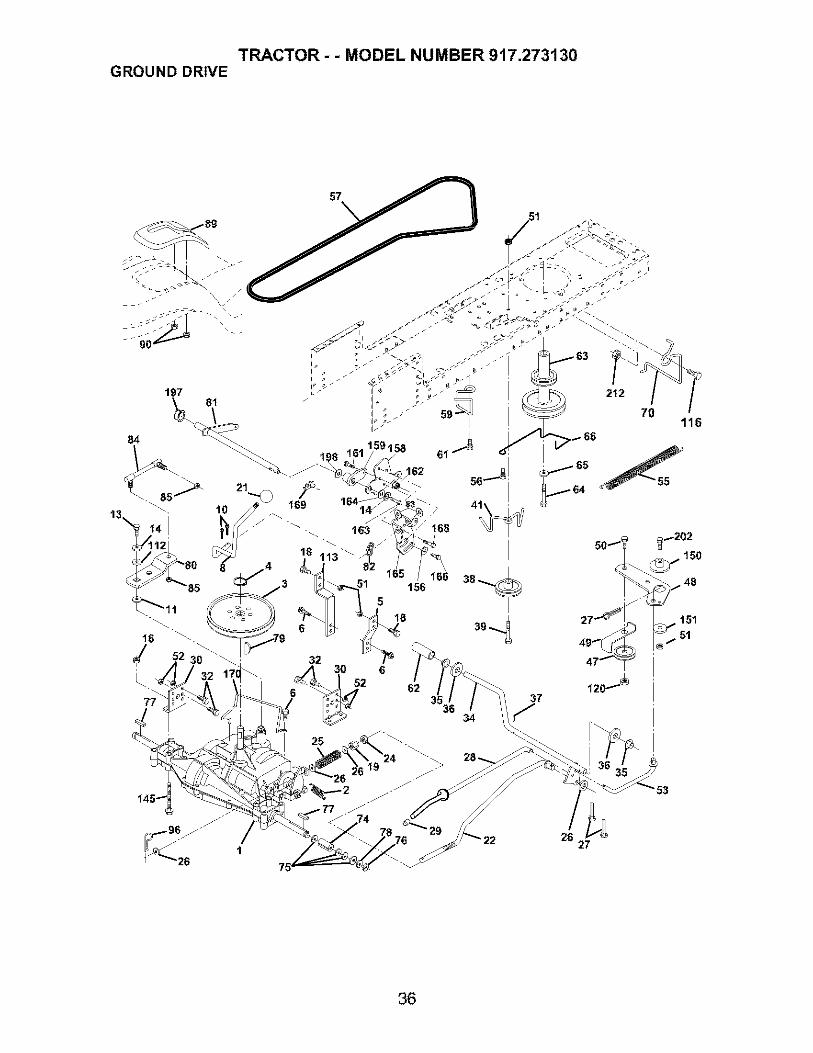
TRACTOR- - MODEL NUMBER 917.273130GROUND DRIVE
57
166156
35
34
47_ °_
37
2627
36
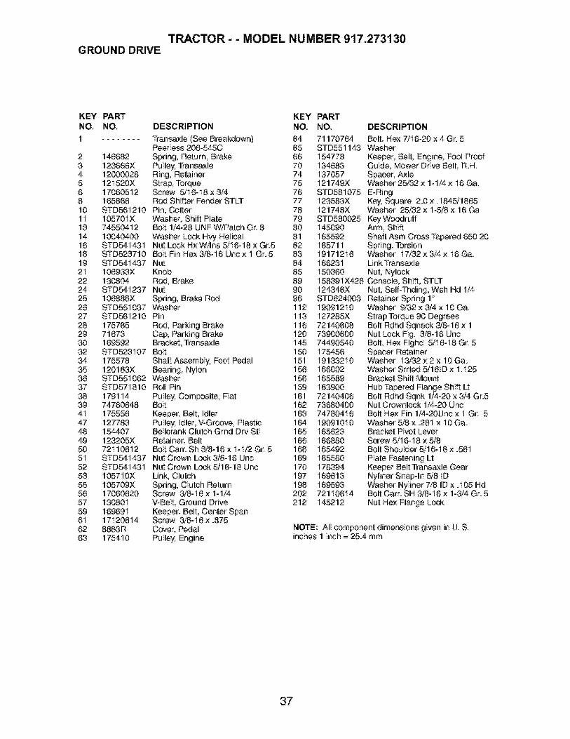
TRACTOR- - MODEL NUMBER 917.273130GROUND DRIVE
KEY PART KEYNO, NO, DESCRIPTION NO,
1 Transa;<le (See Breakdown) 64Peerless 208-545C 65
2 148682 Spring, Return, Brake 663 123668X Pulley. Transaxle 704 12000028 Ring, Retainer 745 121520X Strap, Torque 756 17060512 Screw 5/I8-I8x3/4 768 165868 Rod Shifter Fender STLT 7710 STD561210 Pin, C_tter 7811 10570IX Washer, Shift Plate 7913 74550412 Bolt 1/4-28 UNF W/Patch Gr. 8 8014 10040400 Washer Lock Hvy Helical 8118 STD541431 Nut Lock Hi<W/Ins 5/I6-18 ;<Gr.5 8218 STD523710 Bolt Fin Hex3i8-16 Unc;< 1 Gr.5 8319 STD541437 Nut 842I 108933X Knob 8522 130804 Rod, Brake 8924 STD541237 Nut 9025 108888X Spring, Brake Rod 9628 STD551037 Washer 11227 STD561210 Pin 11328 175765 Rod, Parking Brake 11829 71873 Cap, Parking Brake 12030 169592 Bracket, Transaxle 14532 STD523107 Bolt 15034 175578 Shaft AssembIz Foot Pedal 15I35 120183X Bearing Nylon 15638 STD551062 Washer 15837 STD571810 Roll Pin 15938 179114 Pulley. Composite, Fiat 16I39 74760648 Bolt 1624I 175558 Keeper, Belt, Idler 16947 127783 Pulley. Idler, V-Groove, PlasIic 16448 154407 Bellcrank Clutch Grod Dry Stl 16549 123205X Retainer, Belt 16850 72I 10612 Bolt Cam Sh 3/8-16 x I-I/2 Gr 5 1685I STD541437 Nut Crown Lock3/8-16 Unc 16952 STD541431 Nut Crown Lock 5/16-18 Uoc 17053 105710X Link, Clutch 19755 105709X Spring, Clutch Return 19856 17060620 Screw 3/8-I8;<1-1/4 20257 130801 V-Belt Ground Drive 21259 169691 Keeper, Belt, Center Span6I 17120614 Screw 3/8-I8;<.87562 8883R Cover, Pedal63 175410 Pulley. Engine
PARTNO, DESCRIPTION
71170764 Bolt Hex 7/I6-20 x 4 Gr. 5STD551143 Washer154778 Keeper, Belt, Engine, FOOlProof134683 Guide, Mower Drive Belt, R.H.137057 Spacer, AxleI21749X Washer 25/32 ;<1-1/4 ;< I6 Ga.
STD581075 E-RingI23583X Key. Square 2.0 ;< .I845/1885I21748X Washer 25/82 ;<1-5/8 ;<16 GaSTD580025 Key WoodruffI45090 Arm, ShiftI65592 Shaft Asm Cross Tapered 650 20I65711 Spring, Torsion19171218 Washer I7/32;<3/4;<I6Ga.166231 Link TransaxleI50360 Nut, Nylock15&39IX428 C_nsole, Shift, STLTI24346X Nut, Self-Toding, Wsh Hd 1/4STD824003 Retainer Spring 119091210I27285X721406087390060074490540175456191332101660021655891839007214040873680400747804181909101016562316688016549216558017839416981316959372110614145212
Washer 9/32 ;<3/4 x I 0 Ga.Strap Torque 90 DegreesBolt Rdod Sqneck 3/8-18 ;<1Nut Lock Fig. 3/8-16 UncBolt, Hex Flghd 5/I8-I8 Gr 5Spacer RetainerWasher I3/32 ;<2 x 10 Ga.Washer Srrted 5/181D ;<1I25Bracket Shift MountHub Tapered Flange Shift LtBolt Rdhd Sqnk 1/4-20 x 3/4 Gr.5Nut Crownlock 1/4-20 UncBolt He;<Fin 1/4-20Unc x 1 Gr 5Washer 5/8 x .281 x 10 Ga.Bracket Pivot LeverScrew 5/16-18 ;<5/8Bolt Shoulder 5/16-I 8 ;<.58IPlate Fastening LtKeeper Belt Transaxle GearNyliner Snap-In 5/8 IDWasher Nyliner 7/8 ID x .105 HdBolt Cam SH 3/8-I6 ;<1-3/4 Gr. 5Nut He;<Flange Lock
NOTE: All component dimensions given in U. S.inches 1 inch = 25.4 mm
37

TRACTOR- - MODEL NUMBER 917.273130STEERING ASSEMBLY
I
I _39
\ _ \ I _ _ _ /
29
_8
65
67 67
43
38

TRACTOR- - MODEL NUMBER 917.273130STEERING ASSEMBLY
KEY PARTNO, NO, DESCRIPTION
I234588I0III2I3I5I7282829303238373839404I424344485I548587887I8287889I
1723931898401898396266H121748X12000029175121STD55I 137739408001365I 814521218064 I126847X1913141817060612STD561210130465155099152927
184704)(428 Steering WheelAxle AasemblySpindle Assembly, LH.Spindle Assembly, R.H.Bearing Race, Thrust, HardenedWasher 25/32 x I-5/8 x I 8 Ga.Ring, KlipDraglinkWasher, LockNut Hex Jam Toplock I/2-20 UnfSpacer Bearing Axle FrontNut Hex Flange LockShaft Assembly, SteeringBushing, Link, DragWasher 13/32 x 7/8 x I 8 Ga.Screw 3/8-I6 x 3/4Pin CotterRod TieBushing, SteeringScrew
159948)(428 Insert, Steering Wheel19182411 Washer 9i16IDx I-1/2OD 1I Ga.STD541537 Nut Lock Center 3/8-24 Unf159945 Adaptor, Steering Wheel145054)(428 Boot, Steering Shaft121749X Washer 25/32 x I-I/4 x I8 Ga.180640 Extension Shaft Steering184948)(428 Cap, Spindle735404007113042016036772140618169827175146189835173966175118175553
Nut Crownlock I/4-28Bolt Hex I/4-28 UNF x I-I/4 Gr. 8Spacer Brace AxleBolt RDHD Sqnk 3/8-18x2-1/4Axle, BraceSteering Asm.Bracket Susp. Chassis FrontWasher Flat .781 x 1-I/2 x .14Bolt Shoulder 7/I6-20 UneClip Steering
NOTE: All component dimensions given in U.S. inches1 inch = 25.4 mm
39

TRACTOR- - MODEL NUMBER 917.273130ENGINE
2
_3
38
32_
31
105_
Sl14
_105
_37
4O
I
33
29
OPTIONAL EQUIPMENT
Spark Arrester I
4O

TRACTOR- - MODEL NUMBER 917.273130ENGINE
KEY PARTNO, NO, DESCRIPTION12
170548X505 Control, Throttle17720408 Screw, Hex Head, Thread
Cutting I/4-20× 1/23 Engine, (See Breakdown)
Kohler Model CV490-275084 174667 Muf|ler13 12-041-03 Gasket14 148458 Tube Drain Oil Easy18 STD551237 Washer23 189837 Shield BrniDbr Guard29 137180 Arrestor, Spark3I 184900 Tank, Fuel32 140527 Cap Assembly, Fuel Sears, Vented38 123487X Clamp, Hose37 137040 Line, Fuel38 181654 Plug Drain Oil Easy40 124028X Bushing, Snap, Fuel Line44 17870412 Screw, Hex Washer Head,
Thd., Roll. 1/4-20 x 3/445 17800812 Screw Hxwsh Thdr 3/8-I 8 × 3/448 19091416 Washer 9/32 × 7/8 × 16 Ga77 19101216 Washer 5/I6 × 3/4 × 16 Ga.80 74760508 Bolt Hex Hd 5/I6-18 Unc × 1/2101 M73030800 Nut Flange M8-1.25 Non-Lk Zinc105 17120616 Screw 3/8-I8 × 1
NOTE: All _mponent dimensions given in U.S. inchesI inch = 25.4 mm
41

TRACTOR- - MODEL NUMBER 917.273130SEAT ASSEMBLY
\\
\\\\
II
II
I
tl
12
I I
II
II
I I
5
/ 21
KEY PARTNO, NO, DESCRIPTION
I 160597 Seat2 160188 Bracket Pnt Pivot Seat (blk)3 7I 110616 Bolt Fin Hex 3/8-16unc X 14 19131610 Washer 13/32 X 3/4 X 10 Ga5 145006 Clip Push In Hinged6 STD541437 Nut He;<Lock w/Ins 3/6-I6 Unc7 12416IX Spring Seat Cprsn 2 250 BIk Zi6 17000616 Screw 3/6-I6 X 19 19131614 Washer 13/32 X 1X I4 GaI 0 160166 Pan Pnt Seat (blk)11 166369 Knob Seat Adj Wingnut
KEY PARTNO, NO, DESCRIPTION
12 121246;<13 I21248X14 7205041215 13430016 121250;<17 123976;<21 17165222 STD54143124 19171912
Bracket Pnt Mounting SwitchBushing Snap Bik Ny150 IdBolt Rdhd Sht Nk I/4-20x1-I/2Spacer Split 28 X 96 ZincSpring Cprsn 1 27 BIk PntNut Lock I/4 Lge Fig Gr 5 ZincBolt Shoulder 5/16-I 6 Unc-2ANut He;<Lock w/Ins 5/16-16Washer I7/32 X I-3/16 XI2Ga.
NOTE: All _mponent dimensions given in U.S.inches I inch = 25.4 mm
42

TRACTOR - - MODEL NUMBER 917.273130DECALS
9
16 2 I3 1013 6 3 1I
,I6
II
20
I5
12
KEY PARTNO, NO,
KEY PART
DESCRIPTION NO, NO,
1 156366 Decal, Oper. Instr. 13 1773532 I86443 Decal, Replacement 14 I603963 186280 Decal, Hood, R.H 15 1791284 186281 Decal, Hood, L.H. 16 1848425 I38047 Decal, Battery 17 I846436 133644 Decal, Customer Maintenance 18 1640657 177367 Decal, HP Engine 20 1495168 172331 Decal, Mower Srs - - I383119 186282 Decal, Fender, Craftsman - - I65600X42810 156439 Decal, Fender Danger - - I65799X42611 I86283 Decal, Hood Side - - I8498912 146046 Decal, V-Belt Drive Schematic - - 184990
DESCRIPTION
Decal Dash PanelDecal V-Belt SchematicDecal Deck B 42Decal Grille RHDecal Grille LHDecal Strg. WhlDecal Battery DngriPsn EngDecal Lift HandlePad Footrest LH STLTPad Footrest RH STLTOwner's Manual, EnglishOwner's Manual, Spanish
WHEELS & TIRES
2 _ 5,8
74,10
11
KEY PARTNO. NO, DESCRIPTION
1 591922 651393 I06222X4 599045 I06732X6246 278H7 9040H8 I06108X6249 I22082X10 7152J11 I04757X428-- 144334
Cap Value TireStem ValueTire FTs 15 X 6 0 - 6 ServiceTube Inner Front #35060Rim Asm 6"front White ServiceFitting GreaseBearing FlangeRim Asm 6"rear White ServiceTire R Ts 20 X I0-8 ServiceTube Rear 9 5 X 6 ServiceCap Axle BIk I 50 X 1 00Sealant, Tire (I0 oz. tube)
NOTE: All component dimensions given in U.S. inchesI inch = 25.4 mm
43

TRACTOR - - MODEL NUMBER 917.273130LIFT ASSEMBLY
7
5
13
4
3
2
65
19
13
13----o_32
13
1915
20
44

TRACTOR- - MODEL NUMBER 917.273130LIFT ASSEMBLY
KEY PARTNO, NO, DESCRIPTION
I I59460 Washer Asm Inner Spring W/Plunger2 I59471 Shaft Asm. Lift3 105767X Pin Groove4 12000002 E Ring #5133-625 19211621 Washer 21/32 × 1 ;(2I Ga.6 I20183X Bearing Nylong7 I25631X Grip Handle Fluted8 I22365X Button Plunger Read11 I39865 Link Asm Lilt L.H.I2 139866 Link Asm Lilt R.H.I3 STD624008 Retainer SpringI5 173288 Link FrontI6 73350800 Nut Jam He;( 1/2-I3 Une17 175689 Tru nnion BIk ZincI8 73800800 Nut Look wiWsh I/2-I3 UncI9 139868 Arm Suspension Mower20 163552 Retainer Spring31 I69865 Bearing, Pvt Lift32 73540600 Nut Crownloek 3/8-24
NOTE: All component dimensions given in U.S inches1 inch =254 mm
45

TRACTOR- - MODEL NUMBER 917.273130MOWER DECK
113 111 114
118 _
106/_ 102 193 105
56
\16
10 ...-.-_9_
18
29.18
119 F _117
21
2324
25
42 D ma[t-t-Vulh stl_ 3
46

TRACTOR- - MODEL NUMBER 917.273130MOWER DECK
KEY PART KEY PARTNO, NO, DESCRIPTION NO, NO, DESCRIPTION
1 1658922 STD5331073 1380174 1654605 STD8240086 1780248 8508579 STD55II3710 140298
1I
131415181819202I23242528272829303I323334383740444548485253545556
134149
139775
138971
137645128774110485X17449372140505132827159770STD541431177563105304X123713X110452X
Mower Deck Assembly, 42'BoltBracket Assembly, Sway Bar, FrontBracket Sway Bar 38/42" DeckRetainer SpringBar Sway DeckBolt, Hex 3/8-24 x 1.25 Gr. 8Washer, LockWasher, Hardened(The following blades are availa-ble)Blade, 42" MulehingStd(For mulching mowers only)Blade, 42" Mulching Premium(For better wear when mulching)Blade, 42" Hi-Litt(For bagging or discharing)Shaft AssembIz Mandrel, VentedHousing, Mandrel, VentedBearing Ball, MandrelStripper, Vented Mower DeckBolt, Carriage 5/I 6- I8 x 5/8Bolt, ShoulderBaffle, VortexNut Crownleck 5/16-I 8 UNCBracket, DeflectorCap, SleeveSpring, Torsion, DeflectorNut, Push
130968)(428 Shield, Deflector19111016131491173984129963153535178342STD533717131494STD55I 837STD541437140088STD824003137729133944139888184907178515155048165723
Washer 11/32 x 5/8 x 16 Ga.Rod HingeScrew Thdrol Washer HeadWasher, SpacerPulle_ MandrelNut, Toploek, FlangedBoltPulley. idler, FlatWasher 13/32 x I3/18 x 16Ga.Nut Crownleck 3/8-18 UNCGuard, Mandrel, LH.RetainerScrew, Thd. Roll 1/4-20x5/8Washer, HardenedBolt, Shoulder 5/I6-18 UNCArm Assembly, Pad, BrakeWasher, HardenedArm, IdlerSpacer, Retainer
59 141043 Guard, TUV Idler67 I84939 Knob Custom Oval68 144959 V-Belt92 STD541437 Nut10I 138420 Mulcher Cover102 71081010 Screw103 19061216 Washer #10104 STD551II0 Washer, Lock105 160793 Latch Assembly. Bagger108 2029J Nut, Weld1I I I79292 Bracket Gauge Wheel Lh112 I79293 Bracket Gauge Wheel Rh113 17080510 Screw 5/18-I8 Unc114 73510500 Nut Keps 5/I6-18 Unc118 4898H Bolt Shoulder117 I65746 Wheel Gauge Std118 73930600 Nut Centerlock 3/8-I8 Unc119 19121414 Washer 3/8 x 7/8 x 4 Ga.129 19131312 Washer I3/32 x 13/I6 x 12Ga.130 STD523710 Bolt, Fin Hex 3/8-16 UNC x 1 Gr 513I STD533710 Bolt, Rdhd Sqnk3/8-18UNCx1142 165890 Arm Spring Brake Mower143 157109 Bracket Arm idler 42_144 158834 Keeper Belt 42_Clutch Cable145 165888 Pulleyldler Flat148 I71977 Bolt Carriage idler147 131335 Spring Extension148 169022 Spring Return Idler149 I65898 Retainer Spring Yellow Zinc150 19091216 Washer 9/32 x 3/4 x I6 Ga.15I 169870 Bracket Clutch152 169878 Cable Clutch 42 In
153 I69674 Washer Flat 3/8 °Type B154 169675 Spring Retainer155 169671 Spring Retention Lever156 I69872 Spacer157 169869 Rod Clutch158 I7720408 Screw HexThd Cut I/4-20 x I/2159 72140614 Bolt Rdhd Sqn 3/8-18 Unc x 3/4184 19131410 Washer I3/32 x 7/8 x I0 Ga.
- - I30794 Mandrel Assembly(Includes Housing, Shaft andShaft Hardware Only - Pulley NotIncluded)
- - 169583 Replacement Mower, Complete(Std. Deck-Order separately mul-cher cover and guage wheelcomponents key nos. I01 - I06and II6- II8)
NOTE: All component dimensions given in U.S. inchesI inch = 254 mm
47

TRACTOR- - MODEL NUMBER 917.273130PEERLESS TRANSAXLE - - MODEL NUMBER 206-545C
157
47
35
13
!15
MODEL and SERIALI NUMBERSHERE
79
.51
52
2g35
157
,41A _"/
42A
34
KEYNO.
I234566A788AgI0I1I2I3I4I5I7I82021222525A2627282929A29B29C3031
31A32343535A3637383940
48

TRACTOR- - MODEL NUMBER 917.273130PEERLESS TRANSAXLE - - MODEL NUMBER 206-545C
PARTNO.
772147780086A770128776395776409778364778369778330792180792047784352784378778334778309778368778368778370786188786102792077A792078792079792073A792I 77792125792035788040780072780160780051780199780108780001
780195788083780194780193780197790075790007799021786026792076A
DESCRIPTION
Traasaxle CoverNeedle Bearing 5/8Traasaxle CaseCountershaftOutput ShaftSpur Gear (38 teeth)Spur Gear (I5 teeth)Spur Gear (I 1 teeth)Shilt KeyWoodruff Key #9Shilt _llarShilt Rod & ForkBevel Gear (30 teeth)Input Bevel Pinion (13 teeth)Bevel Gear (I3 teeth) (Include. 14)Bevel Pinion (I3 teeth) (Include. 13)Ring Gear (43 teeth)Drive PinSpacer 1.130 X .695Ball 5/16 ° diaSet Screw 3/8 - I6 x 3/8'Spring .3I 0 OD x .625 LScrew I/4 - 20 × 1-1/4'Screw I/4-20 × I-3/8 °Retaining Ring (pkg of 2)Retaining RingRetaining RingThrust Washer 627 ID x.031WThrust Washer 762 ID x.031WThrust Washer 762 ID x.031WAnti-Rotation Washer 632CupWasher 1.127 ID x 032WFlat Washer 750 ID x .056W(Use As Needed)Flat Washer .750 ID x .062WOil Seal 5/8'Bushing .563Flanged Bushing 5 / 8_ IDFlanged Bushing 75IBrake DiskBrake Pad PlateBrake Pad (pkg of 2)Dowel PinFlat Washer .312 ID x .059W
KEY PARTNO. NO. DESCRIPTION
4IA 790079 Brake Lever42 792073A Screw I/4 - 20 × 1-1/4'42A 792085A Screw I/4 - 20 × 2 I/443 792075 Locknut 5 / I6 - 2444 790025 Brake Pad Holder45 786066 Spacer 2625 × 1.046 786086 Brake Lever Bracket47 774690 A×le (I 1-15 / 16" Long)48 774691 A×le (I 6 - 1 / 2 long)49 778356 Spur Gear (29 teeth)50 778338 Spur Gear (27 teeth)5I 778354 Spur Gear (23 teeth)52 778352 Spur Gear (I9 teeth)53 778350 Spur Gear (I6 teeth)54 778346 Spur Gear (I5 teeth)56 778355 Spur Gear (I 1 teeth)57 778337 Spur Gear (I3 teeth)58 778353 Spur Gear (I7 teeth)59 778351 Spur Gear (21 teeth)60 778349 Spur Gear (24 teeth)6I 778345 Spur Gear (25 teeth)65 780189 Flat Washer .563 ID x .062W66 776422 Input Shaft67 776396 Shitter & Brake Shaft69 792I 70 Retaining Ring70 786187 Spacer .8907I 788069 Square Cut Ring7IB 788092 "0 Ring76 780090 Flat Washer 1.128 ID x .058W77 788078A Inverted Retaining Ring79 792144 Spring .430 OD x .5000 L82 778333 Bevel & Spur Gear (30 & 13 teeth)83 778338 Spur Gear (27 teeth)85 792154 Oil Fill Plug87 788089A Oil Seal 9/16 °150 788093A Liquid Gasket RTV Silicone157 788088A Oil Seal 3/4180 730229A Gear Oil 80W90900 794712 Replacement
MST - 206-545C Transa×le
NOTE: All component dimensions given in U.S. inches1 inch = 25.4 mm
49

TRACTOR- - MODEL NUMBER 917.273130KOHLER ENGINE-MODEL NUMBER CV490, TYPE NUMBER 27508
CYLINDER HEAD, VALVE AND BREATHER J
1
\
CRANKCASEJ
_3 22 1
_-_4
\
\
IO
5O

TRACTOR- - MODEL NUMBER 917.273130KOHLER ENGINE-MODEL NUMBER CV490, TYPE NUMBER 27508
CYLINDER H EADNALVFJBREATH ER CRANKCASE
KEY PART KEY PARTNO, NO, DESCRIPTION NO, NO, DESCRIPTION
1 25_351-01S Liften valve (2)2 12_755-94_S Kit, cylinder head (Includes
3417, Gaskets 12 041 014S(Qty. 2), 12 041 02-8, & 12041 0348)
3 12_411-03_S Rod, push (2)4 12_041410S Gasket, cylinder head5 12_017401S Valve, intake (Std.)
12_017402S Valve, intake (.25)6 12_016-01 S Valve. exhaust (Std.)
12-016-02 S Valve, exhaust (.25)7 25q 39-60-S Plug, allen hd. pipe 1/8"8 12_318436S Cylinder Head9 25_186-01uS Arm, rocker (2)10 12 599-03 S Pivot, rocker arm (2)11 M-640034-S Screw. hex. flange M6xl.0x34
2)12 12_089-01 S Spring, valve (2)13 12q73401_S Cap, valve spring (2)14 12_755-03_S Kit, retainer (2)15 12_468405_SWasher, plain 13/32"16 12q 12413_SSpacer, head bolt exhaust port17 12_086-15_S Screw, hex.flange
M10x1.5x81 (5)18 25_237414_SClamp, hose (2)19 12 326-03 S Hose, breather20 M-6450204S Screw. hex. flange
M6x1.0x20 (5)21 12 096-07_S Cover. valve w/nipple22 M-5450104S Screw. hex. flange
M5x0.Sx1023 12_018401S Retainer. breather reed24 12_402-02_S Reed, breather
1 12_032_03S Seal, crankshaft2 Block, cylinder (Use Short
Block 12 522 51)3 12 445_02-S Strap, lifting4 M-839025-S Screw, hex. flange
M8x1.25x255 24_380q3-S Dowel, locating (4)6 12_755 49 S Kit, camshaft (Includes 7,8)7 12_089_31S Spring, actuating8 12422_08_S Shim, camshaft (A.R.) blue
12-422_09_S Shim. camshaft (A.R.) red12422q0_S Shiml camshaft (A.R.) yellow12422q 1_S Shiml camshaft (A.R.) green12422q2-S Shim. camshaft (A.R.) gray12422q3 S Shiml camshaft (A.R.) black12422 07 S Shim, camshaft (A.R.) white
9 12_144 28 S Shaft, balance10 12_874_07_SPiston w/Ring Set (Std.)
(Includes 11,12)12-874 11S Piston w/Ring Set (.08)12-874 08_S Piston w/Ring Set (.25)12-874_09_S Piston w/Ring Set (.50)
11 12 018 02_S Retainer, piston pin (2)12 12q08 07 S Ring Set (Std.)
12q08 08_S Ring Set (.25)12q08 09 S Ring Set (.50)
13 12-067q 1_S Connecting Rod (Std.)12-067_06_S Connecting Rod (.25)
14 12-380 01_S Pin, governor regulating15 12 043 05 S Gea£ governor16 M-6310054S Washe£ plain 6 mm17 12q44 02-S Shaft, governor gear18 52q39-09 S Plug, cup19 12_755_64_SKit, gov. cross shaft w/clip
(Includes 23)20 X4254102_S Washe£ plain 1/4"21 1203201uS Seal, governor cross shaft22 M-631015-S Washe£ plain 6 mm23 12q54_05 S Clip, hitch pin
NOTE: All component dimensions given in U.S.inches 1 inch = 25.4 mm
51
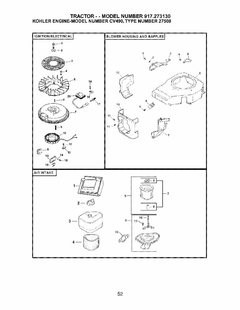
TRACTOR - - MODEL NUMBER 917.273130KOHLER ENGINE-MODEL NUMBER CV490,TYPE NUMBER 27508
IGNITION/ELECTRICAL]
--2
13 J4
BLOWER HOUSING AND BAFFLES 1
12 6
AIR INTAKE I
F_
7
'°112\
52

TRACTOR- - MODEL NUMBER 917.273130KOHLER ENGINE-MODEL NUMBER CV490,TYPE NUMBER 27508
IGNITION_ELECTRICALBLOWER HOUSING & BAFFLES
KEY PART KEY PARTNO, NO, DESCRIPTION NO, NO, DESCRIPTION
1 12_086-14_S Screw, hex. flangeM10x1.5×46
2 12_468-03 S Washer, plain 3/8"3 24q62-03 S Screen, grass4 25_086-47_S Bolt, shoulder M6x1.0x16 (4)5 12 157-06 S Fan6 X42_15-S Key7 12_025-15 S Flywheel8 12 155-09_S Connector9 M-548025-S Screw. hex. cap M5xO.Sx25 (2)10 12-065-09_S Stator -15 amp with stator
brake11 M-545020-S Screw. hex. flange
M5x0.Sx20 (2)12 12 154-06 S Clip, cable (2)13 41_403-09_S Regulator, rectifier - 15 amp14 X_22q1-S Washeq lock 1/4"15 M-639016-S Screw. hex.flange
M6x1.0xl 6 (2)16 236602-S Connector17 12q 32-02_S Spark Plug18 X_728 1-S Clip, cable (2)19 M-545010-S Screw, hex. flange
M5x0.Sxl 0 (2)20 12-584-04_S Module, ignition
NOT ILLUSTRATED12 176-44_S Harness, wiring24_518-12-S Lead, black (6" - 12 gauge-
insulated grip barrel eyeletterminals)
12_518-35_S Lead, white (36" _18 gaugefully insulated push on tab
and unineulatad socketterminals)
234
56789
1011
12
M-545010-S Screw. hex. flangeM5x0.Sxl0 (6)
24 468q0 S Washer, plain 1/4"12 146 07 S Plate, blower housingM-550010-S Screw. hex. flange
M5x0.8xl 024_096 05_S Cover. pinion12-027_76-S Housing, blower12_063q8-S Baffle, intak_ side25 154_02_S Clip, mounting (3)12_086 37_S Screw. captive washer
M5x0.Sx20 (3)12 063 20_S Baffle, cylinder headM-645016-S Screw, hex. flange
M6xl .Oxl 6 (2)12_063 lg_S Baffle, cylinder
NOT ILLUSTRATEDM-541050-8 Nut. hex.flange M5x0.6
AIR INTAKEtFILTRATION
KEY PARTNO, NO, DESCRIPTION
123456
789
12_261 01 S25341_03-S12-096 24_S12-083 _12-S12-100 08_S12_083 _10S
12-743 12_S12-032 11uS12_094_07_S
Duct, airKnob, air cleaner coverCover, air cleanerPreoleaneq elementWing NutKit, air cleaner element(Includes 5.7, 8)Filter, element (Includes 5, 8)Seal 17/16"Base, air cleaner (Includes11,12)
10 12-072 04-S Stud, mounting plateM6x1.0x75
11 12-086-01-S Screw, #10 HFLo threadforming (2)
13 12-041-02-S Gasket. air cleaner
NOT ILLUSTRATED12_113_53_S Decal, air cleaner
NOTE: All component dimensions given in U.S.inches 1 inch = 25.4 mm
53

TRACTOR- - MODEL NUMBER 917.273130KOHLER ENGINE-MODEL NUMBER CV490, TYPE NUMBER 27508
STARTING SYSTEM I
!L
0
I
m_
°-1
ENGINE CONTROLSJ
17
!
11
OIL PAN / LUBRICATION
_...._o
i
'II
0--4
@\
54

TRACTOR - - MODEL NUMBER 917.273130KOHLER ENGINE-MODEL NUMBER CV490, TYPE NUMBER 27508
STARTING SYSTEM ENGINE CONTROLS
KEY PART KEY PARTNO, NO, DESCRIPTION NO, NO,
M-839070-S Screw, hex. flangeMgx1.25x79 (2)
25-098-07 S Starter assembly (Includes 3-8)12-755-54-S Kit, drive end12-227-18-S Cap, drive end12-179-05 S Armature12-221-01-S Kit, brush & spring12-227-13 S Cap, commutator end12-211-01-S Bolt, he×. flange 1t4-29x4-5/8
(2)
2345678
OIL PAN,/LU B RICATION
KEY PARTNO, NO, DESCRIPTION
1 12u038-01S Dipstickassembly (Includes2-3)
2 25u755-13 S Kit, oil fill cap (Includes 3)3 12u153-03 S O-Ring, oil fill cap4 12q53-02 S O-Ring, upper oil fill tube5 12 123-04-S Tube, oil fill6 M-645025-S Screw. hex. flange M6×1.0×257 12-153-01 S O-Ring, lower oil fill tube8 25q62-07uS Screen, oil pickup9 12 096-03_S Cover. oil pickup screen19 M-545016-S Screw. hex.flange M5x0.Sx1611 25u462-09uS Valve, oil pressure relief12 52-059-02-S Filter. oil13 25q 39-57 S Plug, sq. hd. solid 3/8'*14 12u393-01 S Pump, oil15 12q53-06 S O-Ring, oil pump cover19 12 096-34 S Cover, oil pump17 M-545016-S Screw. hex.flange M5x0.Sx16
18 12 032-03 S _'eal, oil (RT.O. end)19 24u086-16 S Screw, hex.flange MSx1.25×45
01)29 24u086- 17uS Screw, hex. flange M8x1.25×4521 12q99-56 S Assembly, Pan, oil (Incl. 11,14-
17)
DESCRIPTION
1 12-979q 1uS Linkage, choke2 12-237-01 S Clamp, cable3 24 986_43_S Screw. hex. flange4 M-664029-S Screw, lobed socket
Mgxl.0x20 (2)5 12u539 10 S Control, speed assembly
(Includes 6u9)6 M-443025-S Screw, pan head M4xg.7x257 M-443029-S Screw. pan head M4xg.7x208 12_989q 1S Spring, choke (2)9 12_989 23_S Spring, choke return19 12-989-24 S Spring, governor11 12u755u83S Kit, governor lever (Includes
12-14)12 12q09 07 S Nut, hex flange 1/4-2913 52-211-04 S Bolt, 1/4u20xl "14 12u999u28-S Lever, governor15 25 158 08uS Bushing, throttle linkage19 12u979u10uSLinkage, throttle17 2515911uS Bushing, throttle linkage
NOTE: All component dimensions given in U.S.inches 1 inch = 25.4 mm
55

TRACTOR- - MODEL NUMBER 917.273130KOHLER ENGINE-MODEL NUMBER CV490, TYPE NUMBER 27508
CRANKSHAFT J
FUELSYSTEM I
EXHAUST ]
5
7
/
/
56

TRACTOR- - MODEL NUMBER 917.273130KOHLER ENGINE-MODEL NUMBER CV490, TYPE NUMBER 27508
FUEL SYSTEM
KEY PARTNO, NO, DESCRIPTION
1 M-641060-S Nut, hex. flange M6x1.0 (2)2 M-629116S Stud M6x1.0x116 (2)3 12-853-118-S Kit, carburetor wtgaeket
(Includes 4,5,6 qty 1Tie,cable 12-454-03-S. Terminal25 452-20 S)
4 12-041-02-S Gasket, aircleaner5 12-053-118 Carburetor assembly (For
information only notavailable separately)(Includes Kit, float 12-757-02-S Kit, carburetor repair12-757-03 S, Kit, solenoidrepair 12-757-33 S)
6 Gasket. carburetor (2)7 Deflector. heat8 Clamp. hose (2)9 Line, fuel 12q/4"10 Filter. fuel in line11 Clip cable
12_041-01 -S12_265_06-S25-237-14_S52_353-22_S25-050-03-S47-154-01-S
NOT ILLUSTRATED*M-561010 S Screw. thread forming
*X-22-11 -S12-757-02-S12-757-03-S12-041-01-S12-041-02-S12-041-05-S12-041-06-S12-032-06-S12-757-33-S12-041-06-S12-454-03-S25-452-20-S12-518-37-S
M5x0.Sxl 0Washer, lock 1/,$"Kit, floatKit, carburetor repairGasket, carburetorGasket, air cleanerGasket, bowlGasket, bowl screwSeal, solenoidKit, solenoid repairGasket, bowl screwTie cableTerminalLead, red, (37" _20 gauge -insulated socket anduninsulated socketterminals)
*attaches carburetor ground lead to curb baffle.
CRANKSHAFT
KEY PARTNO, NO, DESCRIPTION
1 12_014-57-S Crankshaft (Includes 2)2 25-139-27-S Plug, cup
EXHAUST
KEY PARTNO, NO, DESCRIPTION
1 25-072-04_S Stud, M8x1.25x33(2)2 12_041_03-S Gasket, exhaust manifold3 12_126-11_S Bracket muffler4 12-445-06-S Strap, lifting5 M-645025 S Screw. hex. flange M6xl.0x25
(2)
PA-27508 Replacement Engine12_522_51 Short Block12-755_93_S Gasket Set
NOTE: All component dimensions given in U.S.inches 1 inch = 25.4 mm
57

58

SUGGESTED GUIDE FOR SIGHTING SLOPES FOR SAFE OPERATION
_o
1. Fold this page along dotted line indicated above.2. Hold page before you so that its left edge is vertically parallel to a tree
trunk or other upright structure.3. Sight across the fold in the direction of hill slope you want to measure.4. Compare the angle of the fold with the slope of the hill.

Get it fixed, at your home or ours!
Your Home
For repair - in your home - of all major brand apphances,lawn and garden equipment, or heating and coohng systems,
no matter who made it, no matter who sold itt
For the replacement parts, accessories andowner's manuals that you need to do-it-yourself.
For Sears professional _nstallahon of home apphancesand items hke garage door openers and water heaters.
1-800-4-MY-HOME ® Anytime, day or night
(1-800-469-4663) (U S A and Canada)www.sears.com www.sears.ca
Our Home
For repair of carry-_n products hke vacuums, lawn equipment,and electronics, call or go on-hne for the nearest
Sears Parts and Repair Center.
1-800-488-1222 Anytime, dayor mgrTt (U S A only)
www.sears.com
To purchase a protection agreement (U S A )or maintenance agreement (Canada) on a product serwced by Sears
1-800-827-6655 (u S A) 1-800-361-6665 (Canada)
Para ped_rserv_c_ode reparac_Sna dom_c_ho,y para ordenar #ezas:
1-888-SU-HOGAR su(1-888-_t47_427)
Au Canada pour serv=ceen franqa=s:1-800-LE-FOYER Mc
(.1-800-533-6937)www sears ca
S /ARS®Sears, Roebuck ar_ C&
®Regtstered Tra,dema,rk/ _Tra,dernark / s _Serwce Ma,rk of Sea,rs, RoeL_uckand Co® Marca, Refltstra,da, t._Ma.rca de F_t0r_ca.,s _ Marca. de Serwcto de Sea,rs, Roe0uck arid Co.
_'-Marque de COlhlherce ,' _L,Ma,rque deposee de Sears Roebuck a,r_dCo
184989 Rev. 2 7.24.03 TRiMH Printed in U.S.A.