Crack Identification in Reinforced Concrete Beams · PDF fileUDC 539.4 Crack Identification in...
13
UDC 539.4 Crack Identification in Reinforced Concrete Beams Using ANSYS Software L. Dahmani, a A. Khennane, b and S. Kaci a a Mouloud Mammeri University, Tizi-Ouzou, Algeria b University of Southern Queensland, Toowoomba, Australia ÓÄÊ 539.4 Àíàëèç ðàçâèòèÿ òðåùèí â æåëåçîáåòîííûõ áàëêàõ ñ ïîìîùüþ ïðîãðàììû ANSYS Ë. Äàõìàíè à , À. Õåííàíå á , Ñ. Êàöè à à Óíèâåðñèòåò èì. Ìóëóäà Ìàììåðè, Òèçè-Óçó, Àëæèð á Óíèâåðñèòåò Þæíîãî Êâèíñëåíäà, Òóâóìáà, Àâñòðàëèÿ Ðàçðàáîòàíà òðåõìåðíàÿ íåëèíåéíàÿ êîíå÷íîýëåìåíòíàÿ ìîäåëü æåëåçîáåòîííîé áàëêè. Äëÿ ÷èñëåííîãî ìîäåëèðîâàíèÿ èñïîëüçîâàëñÿ ñòàíäàðòíûé êîíå÷íîýëåìåíòíûé ïàêåò ïðîãðàìì ANSYS 8.0. Ñ èñïîëüçîâàíèåì îáúåìíûõ êîíå÷íûõ ýëåìåíòîâ òèïà SOLID65 ðàçðóøåíèå áåòîíà ïðè ñæàòèè ìîäåëèðîâàëîñü ñ ïîìîùüþ àëãîðèòìà ïëàñòè÷íîñòè, òîãäà êàê åãî ðàñ- òðåñêèâàíèå â çîíå ðàñòÿæåíèÿ îïèñûâàëîñü íåëèíåéíîé ìîäåëüþ ìàòåðèàëà. Ó÷åò ñòàëü- íîãî àðìèðîâàíèÿ áàëêè ïðîèçâîäèòñÿ äëÿ ðàçëè÷íûõ îáúåìíûõ äîëåé ñòàëè â áåòîíå. Äëÿ áåòîííîé áàëêè áåç àðìèðîâàíèÿ ðåçóëüòàòû ðàñ÷åòîâ ñ ïîìîùüþ ïðîãðàììû ANSYS ñðàâíè- âàþòñÿ ñ àíàëèòè÷åñêèìè ðàñ÷åòàìè. Ïðè ýòîì ïîëó÷åíà èõ õîðîøàÿ ñõîäèìîñòü. Ïîêàçàíà ïðèìåíèìîñòü ìîäåëè äëÿ îöåíêè êðèòè÷åñêèõ çîí ðàñòðåñêèâàíèÿ, çàãðóçîê è ïåðåìåùåíèé â æåëåçîáåòîííûõ áàëêàõ ïðè ðàçëè÷íîãî ðîäà íàãðóæåíèè. Êëþ÷åâûå ñëîâà: íåëèíåéíîå êîíå÷íîýëåìåíòíîå ìîäåëèðîâàíèå, æåëåçî- áåòîííàÿ áàëêà, ïðîãðàììà ANSYS, òðåùèíû, ñòàòè÷åñêèé àíàëèç. Introduction. Concrete structural components require the understanding into the responses of these components to a variety of loadings. There are a number of methods for modeling the concrete structures through both analytical and numerical approaches [1, 2]. Finite element (FE) analysis is a numerical one widely applied to the concrete structures based on the use of the nonlinear behavior of materials. FEA provides a tool that can simulate and predict the responses of reinforced and prestressed concrete members. A number of commercial FE analysis codes are available, along with the advanced modules for complex analyses. The use of FEA has increased because of progressing knowledge and capability of computer package and hardware. Any attempts for engineering analyses can be done conveniently and fast using such versatile FE analysis packages. Nonlinear material models have been integrated in many of general purpose finite element codes, i.e., ABAQUS, ANSYS, STRAND7, or MSC.NASTRAN. Those nonlinear © L. DAHMANI, A. KHENNANE, S. KACI, 2010 ISSN 0556-171X. Ïðîáëåìû ïðî÷íîñòè, 2010, ¹ 2 141
Transcript of Crack Identification in Reinforced Concrete Beams · PDF fileUDC 539.4 Crack Identification in...
UDC 539.4
Crack Identification in Reinforced Concrete Beams Using ANSYS
Software
L. Dahmani,a
A. Khennane,b
and S. Kacia
a Mouloud Mammeri University, Tizi-Ouzou, Algeria
b University of Southern Queensland, Toowoomba, Australia
ÓÄÊ 539.4
Àíàëèç ðàçâèòèÿ òðåùèí â æåëåçîáåòîííûõ áàëêàõ ñ ïîìîùüþ
ïðîãðàììû ANSYS
Ë. Äàõìàíèà, À. Õåííàíå
á, Ñ. Êàöè
à
à Óíèâåðñèòåò èì. Ìóëóäà Ìàììåðè, Òèçè-Óçó, Àëæèð
á Óíèâåðñèòåò Þæíîãî Êâèíñëåíäà, Òóâóìáà, Àâñòðàëèÿ
Ðàçðàáîòàíà òðåõìåðíàÿ íåëèíåéíàÿ êîíå÷íîýëåìåíòíàÿ ìîäåëü æåëåçîáåòîííîé áàëêè. Äëÿ
÷èñëåííîãî ìîäåëèðîâàíèÿ èñïîëüçîâàëñÿ ñòàíäàðòíûé êîíå÷íîýëåìåíòíûé ïàêåò ïðîãðàìì
ANSYS 8.0. Ñ èñïîëüçîâàíèåì îáúåìíûõ êîíå÷íûõ ýëåìåíòîâ òèïà SOLID65 ðàçðóøåíèå
áåòîíà ïðè ñæàòèè ìîäåëèðîâàëîñü ñ ïîìîùüþ àëãîðèòìà ïëàñòè÷íîñòè, òîãäà êàê åãî ðàñ-
òðåñêèâàíèå â çîíå ðàñòÿæåíèÿ îïèñûâàëîñü íåëèíåéíîé ìîäåëüþ ìàòåðèàëà. Ó÷åò ñòàëü-
íîãî àðìèðîâàíèÿ áàëêè ïðîèçâîäèòñÿ äëÿ ðàçëè÷íûõ îáúåìíûõ äîëåé ñòàëè â áåòîíå. Äëÿ
áåòîííîé áàëêè áåç àðìèðîâàíèÿ ðåçóëüòàòû ðàñ÷åòîâ ñ ïîìîùüþ ïðîãðàììû ANSYS ñðàâíè-
âàþòñÿ ñ àíàëèòè÷åñêèìè ðàñ÷åòàìè. Ïðè ýòîì ïîëó÷åíà èõ õîðîøàÿ ñõîäèìîñòü. Ïîêàçàíà
ïðèìåíèìîñòü ìîäåëè äëÿ îöåíêè êðèòè÷åñêèõ çîí ðàñòðåñêèâàíèÿ, çàãðóçîê è ïåðåìåùåíèé â
æåëåçîáåòîííûõ áàëêàõ ïðè ðàçëè÷íîãî ðîäà íàãðóæåíèè.
Êëþ÷åâûå ñëîâà: íåëèíåéíîå êîíå÷íîýëåìåíòíîå ìîäåëèðîâàíèå, æåëåçî-
áåòîííàÿ áàëêà, ïðîãðàììà ANSYS, òðåùèíû, ñòàòè÷åñêèé àíàëèç.
Introduction. Concrete structural components require the understanding into
the responses of these components to a variety of loadings. There are a number of
methods for modeling the concrete structures through both analytical and numerical
approaches [1, 2]. Finite element (FE) analysis is a numerical one widely applied
to the concrete structures based on the use of the nonlinear behavior of materials.
FEA provides a tool that can simulate and predict the responses of reinforced and
prestressed concrete members. A number of commercial FE analysis codes are
available, along with the advanced modules for complex analyses. The use of FEA
has increased because of progressing knowledge and capability of computer
package and hardware. Any attempts for engineering analyses can be done
conveniently and fast using such versatile FE analysis packages. Nonlinear
material models have been integrated in many of general purpose finite element
codes, i.e., ABAQUS, ANSYS, STRAND7, or MSC.NASTRAN. Those nonlinear
© L. DAHMANI, A. KHENNANE, S. KACI, 2010
ISSN 0556-171X. Ïðîáëåìû ïðî÷íîñòè, 2010, ¹ 2 141
models play a vital role in nonlinear response analyses since each material
component tends to possess the complicated stress-strain behavior. Among those
packages, ANSYS [3] provides a three-dimensional element (SOLID65) with the
nonlinear model of brittle materials similar to the concrete materials. The element
features a smeared crack analogy for cracking in tension zones and a plasticity
algorithm to take into account the concrete crushing in compression zones. It is
eight-nodded solid isoparametric element with the integration points for the
cracking and crushing checks. The linear elastic behavior governs the analyses
until exceeding either the specified tensile or compressive strengths. Once the
principal stresses at the integration points reach the tensile or compressive strength,
the cracking or crushing of concrete elements can be formed. Then, the cracked or
crushed regions will form in perpendicular with the locally redistributed residual
stresses to the direction of principal stress. These require the nonlinear iterative
solution with high performance computer [4, 5].
1. Finite Element Modeling.
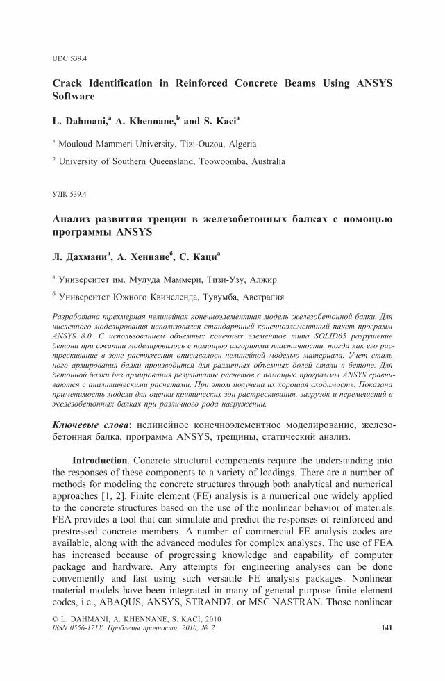
1.1. Reinforced Concrete. An eight-node solid element (SOLID65) was used
to model the concrete. The solid element has eight nodes with three degrees of
freedom at each node – translations in the nodal x , y , and z directions. The
element is capable of plastic deformation, cracking in three orthogonal directions,
and crushing. The geometry and node locations for this element type are shown in
Fig. 1.
1.2. Steel Reinforcement. To model concrete reinforcing, one of two methods
is usually followed. In the first method, the reinforcing is simulated as spar
elements with geometric properties similar to the original reinforcing (Fig. 2a).
These elements can directly be generated from the nodes in the model. This method
of discretization is useful in simple concrete models. The second idealization of steel
reinforcing is the smeared concrete element method (used in this paper). In this
case, the concrete and the reinforcing are discretized into elements with the same
geometrical boundaries and the effects of reinforcing are averaged within the
pertaining element (Fig. 2b). Cracks can also be idealized into either the discrete
type or the smeared type.
Since the SOLID65-3D concrete element simulates tension and compression
in reinforcing bars, the volumetric ratio of reinforcing steel to concrete along with
the direction of the steel had to be provided for each volume, in order for the
L. Dahmani, A. Khennane, and S. Kaci
142 ISSN 0556-171X. Ïðîáëåìû ïðî÷íîñòè, 2010, ¹ 2
Fig. 1. SOLID65: 3D reinforced concrete solid (ANSYS 8.0).

program to account for the reinforcing steel. The required steel properties include
density, modulus of elasticity, and Poisson’s ratio are shown in Table 1.
1.3. FE Model Input Data. For concrete, ANSYS requires input data for
material properties as follows: elastic modulus Eb , ultimate uniaxial compressive
strength f c , ultimate uniaxial tensile strength (modulus of rupture) f r , Poisson’s
ratio �, shear transfer coefficient �, and compressive uniaxial stress-strain
relationship for concrete. The shear transfer coefficient, �, represents conditions of
the crack face. The value of � t ranges from 0 to 1.0, with 0 representing a smooth
crack (complete loss of shear transfer) and 1.0 representing a rough crack (no loss
of shear transfer) (ANSYS 8.0). The value of � used in many studies of reinforced
concrete structures, however, varied between 0.2 and 0.5 [1, 2, 6]. A number of
preliminary analyses were attempted in this study with various values for the shear
transfer coefficient within this range, but convergence problems were encountered
at low loads with � less than 0.2. Therefore, the shear transfer coefficient used in
this study was equal to 0.3.
1.4. Failure Criteria for Concrete. The model is capable of predicting failure
for concrete materials. Both cracking and crushing failure modes are accounted for.
The two input strength parameters – i.e., ultimate uniaxial tensile and compressive
strengths – are needed to define a failure surface for the concrete. Consequently, a
criterion for failure of the concrete due to a multiaxial stress state can be calculated
[7, 8]. In a concrete element, cracking occurs when the principal tensile stress in
any direction lies outside the failure surface [1]. After cracking, the elastic modulus
of the concrete element is set to zero in the direction parallel to the principal tensile
stress direction. Crushing occurs when all principal stresses are compressive and
Crack Identification in the Reinforced Concrete Beam ...
ISSN 0556-171X. Ïðîáëåìû ïðî÷íîñòè, 2010, ¹ 2 143
T a b l e 1
Material Properties for ANSYS FE Model
Material Density
(kg/m3)
Modulus
of elasticity
(MPa)
Poison’s
ratio
Fc28
(MPa)
Ft 28
(MPa)
Fy
(MPa)
Concrete 2400 30,000 0.2 30 3 –
Reinforced
steel
7850 200,000 0.3 – – 240
a b
Fig. 2. Discrete vs. smeared element for concrete reinforcing.
lie outside the failure surface; subsequently, the elastic modulus is set to zero in all
directions [3], and the element effectively disappears.
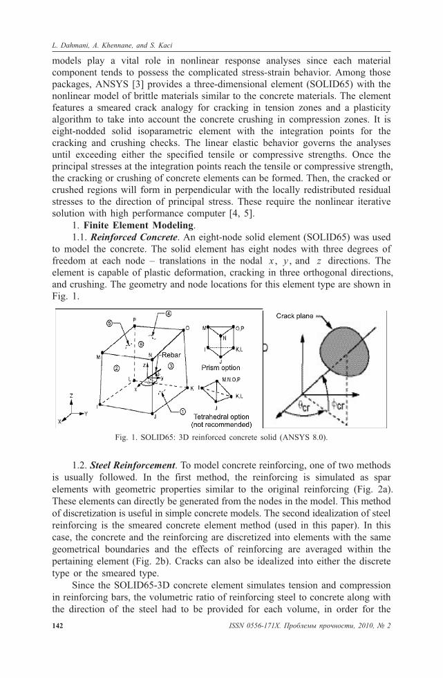
1.5. FE Discretization. As an initial step, a finite element analysis requires
meshing of the model (Fig. 3). In other words, the model is divided into a number
of small elements, and after loading, stress and strain are calculated at integration
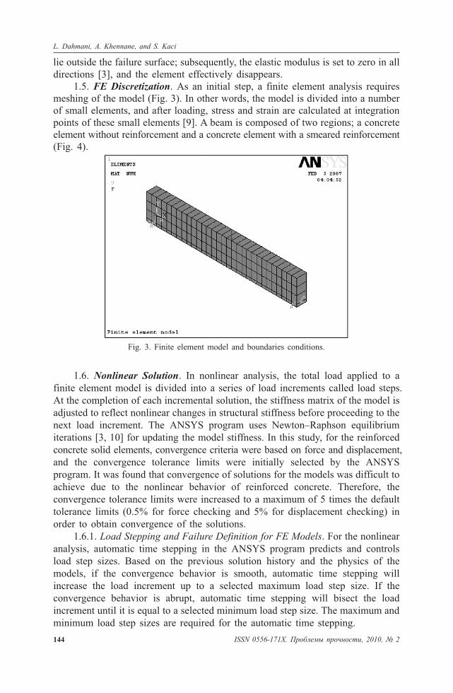
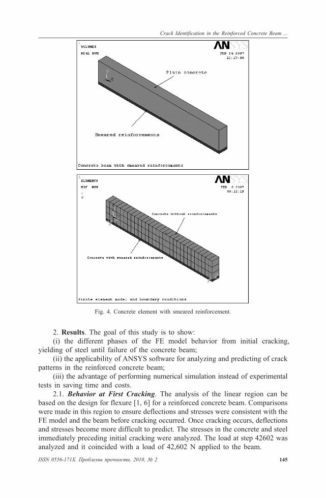
points of these small elements [9]. A beam is composed of two regions; a concrete
element without reinforcement and a concrete element with a smeared reinforcement
(Fig. 4).
1.6. Nonlinear Solution. In nonlinear analysis, the total load applied to a
finite element model is divided into a series of load increments called load steps.
At the completion of each incremental solution, the stiffness matrix of the model is
adjusted to reflect nonlinear changes in structural stiffness before proceeding to the
next load increment. The ANSYS program uses Newton–Raphson equilibrium
iterations [3, 10] for updating the model stiffness. In this study, for the reinforced
concrete solid elements, convergence criteria were based on force and displacement,
and the convergence tolerance limits were initially selected by the ANSYS
program. It was found that convergence of solutions for the models was difficult to
achieve due to the nonlinear behavior of reinforced concrete. Therefore, the
convergence tolerance limits were increased to a maximum of 5 times the default
tolerance limits (0.5% for force checking and 5% for displacement checking) in
order to obtain convergence of the solutions.
1.6.1. Load Stepping and Failure Definition for FE Models. For the nonlinear
analysis, automatic time stepping in the ANSYS program predicts and controls
load step sizes. Based on the previous solution history and the physics of the
models, if the convergence behavior is smooth, automatic time stepping will
increase the load increment up to a selected maximum load step size. If the
convergence behavior is abrupt, automatic time stepping will bisect the load
increment until it is equal to a selected minimum load step size. The maximum and
minimum load step sizes are required for the automatic time stepping.
144 ISSN 0556-171X. Ïðîáëåìû ïðî÷íîñòè, 2010, ¹ 2
L. Dahmani, A. Khennane, and S. Kaci
Fig. 3. Finite element model and boundaries conditions.
2. Results. The goal of this study is to show:
(i) the different phases of the FE model behavior from initial cracking,
yielding of steel until failure of the concrete beam;
(ii) the applicability of ANSYS software for analyzing and predicting of crack
patterns in the reinforced concrete beam;
(iii) the advantage of performing numerical simulation instead of experimental
tests in saving time and costs.
2.1. Behavior at First Cracking. The analysis of the linear region can be
based on the design for flexure [1, 6] for a reinforced concrete beam. Comparisons
were made in this region to ensure deflections and stresses were consistent with the
FE model and the beam before cracking occurred. Once cracking occurs, deflections
and stresses become more difficult to predict. The stresses in the concrete and steel
immediately preceding initial cracking were analyzed. The load at step 42602 was
analyzed and it coincided with a load of 42,602 N applied to the beam.
ISSN 0556-171X. Ïðîáëåìû ïðî÷íîñòè, 2010, ¹ 2 145
Crack Identification in the Reinforced Concrete Beam ...
Fig. 4. Concrete element with smeared reinforcement.
Calculations to obtain the concrete stress, steel stress and deflection of the
beam at a load of 42,602 N are given in Appendix. A comparison of values
obtained from the FE model and Appendix can be seen in Table 2. The maximums
exist in the constant-moment region of the beam during load application. This is
where we expect the maximums to occur. The results in Table 2 indicate that the
FE analysis of the beam prior to cracking is acceptable.
The cracking pattern(s) in the beam can be obtained using the Crack/Crushing
plot option in ANSYS. Vector Mode plots must be turned on to view the cracking
in the model. The initial cracking of the beam in the FE model corresponds to a
load of 42,602 N that induces stress just beyond the modulus of rupture of the
concrete (3.0 MPa) as shown in Table 2. This compares well with the load of
40,476 N calculated in Appendix.
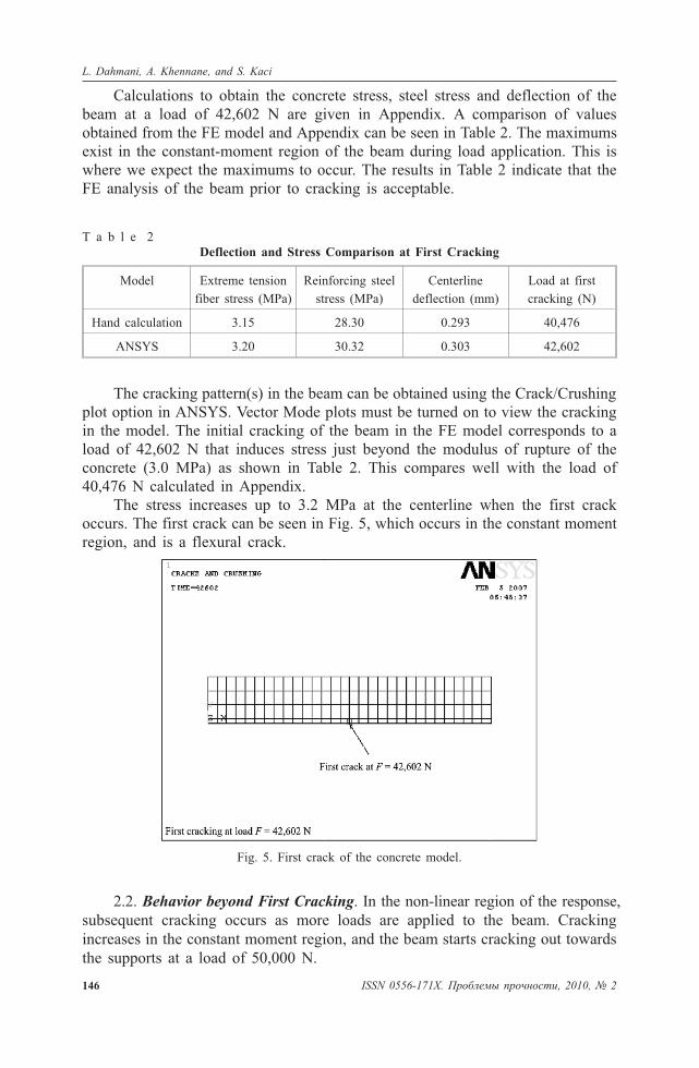
The stress increases up to 3.2 MPa at the centerline when the first crack
occurs. The first crack can be seen in Fig. 5, which occurs in the constant moment
region, and is a flexural crack.
2.2. Behavior beyond First Cracking. In the non-linear region of the response,
subsequent cracking occurs as more loads are applied to the beam. Cracking
increases in the constant moment region, and the beam starts cracking out towards
the supports at a load of 50,000 N.
146 ISSN 0556-171X. Ïðîáëåìû ïðî÷íîñòè, 2010, ¹ 2
L. Dahmani, A. Khennane, and S. Kaci
T a b l e 2
Deflection and Stress Comparison at First Cracking
Model Extreme tension
fiber stress (MPa)
Reinforcing steel
stress (MPa)
Centerline
deflection (mm)
Load at first
cracking (N)
Hand calculation 3.15 28.30 0.293 40,476
ANSYS 3.20 30.32 0.303 42,602
Fig. 5. First crack of the concrete model.
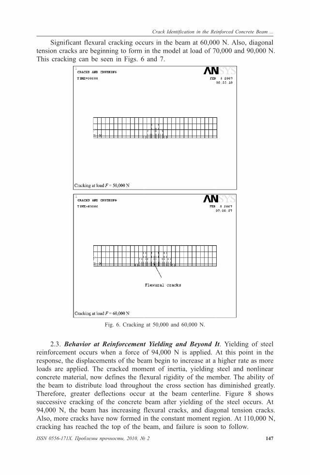
Significant flexural cracking occurs in the beam at 60,000 N. Also, diagonal
tension cracks are beginning to form in the model at load of 70,000 and 90,000 N.
This cracking can be seen in Figs. 6 and 7.
2.3. Behavior at Reinforcement Yielding and Beyond It. Yielding of steel
reinforcement occurs when a force of 94,000 N is applied. At this point in the
response, the displacements of the beam begin to increase at a higher rate as more
loads are applied. The cracked moment of inertia, yielding steel and nonlinear
concrete material, now defines the flexural rigidity of the member. The ability of
the beam to distribute load throughout the cross section has diminished greatly.
Therefore, greater deflections occur at the beam centerline. Figure 8 shows
successive cracking of the concrete beam after yielding of the steel occurs. At
94,000 N, the beam has increasing flexural cracks, and diagonal tension cracks.
Also, more cracks have now formed in the constant moment region. At 110,000 N,
cracking has reached the top of the beam, and failure is soon to follow.
ISSN 0556-171X. Ïðîáëåìû ïðî÷íîñòè, 2010, ¹ 2 147
Crack Identification in the Reinforced Concrete Beam ...
Fig. 6. Cracking at 50,000 and 60,000 N.

148 ISSN 0556-171X. Ïðîáëåìû ïðî÷íîñòè, 2010, ¹ 2
L. Dahmani, A. Khennane, and S. Kaci
Fig. 7. Further cracking at 70,000 and 90,000 N.
Fig. 8. Increased cracking after yielding of reinforcement.
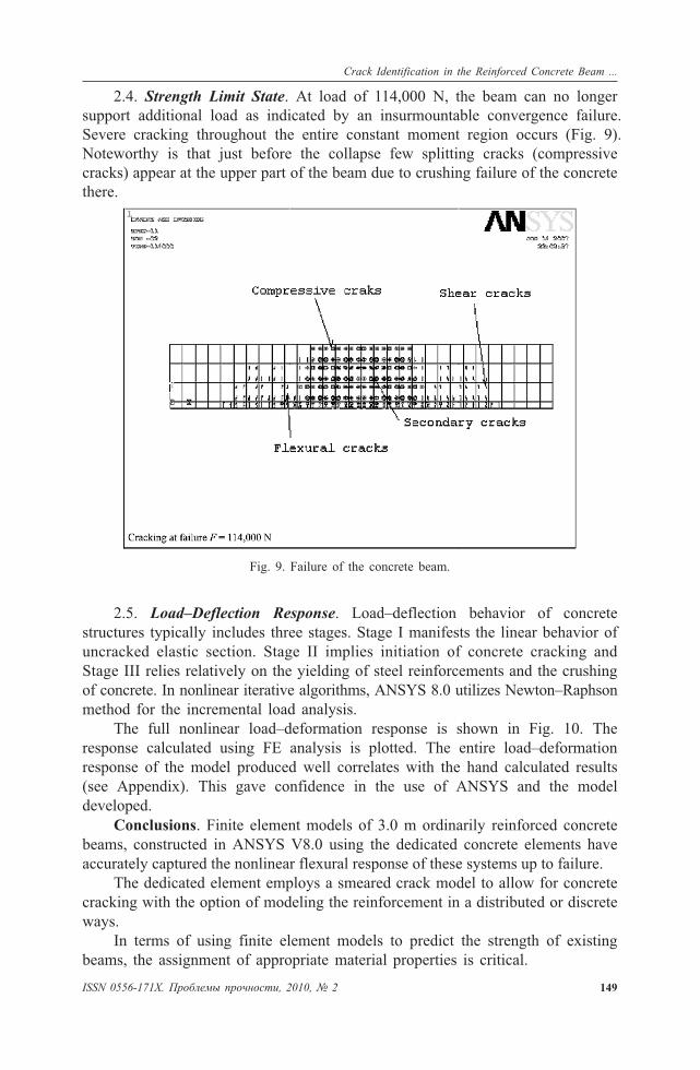
2.4. Strength Limit State. At load of 114,000 N, the beam can no longer
support additional load as indicated by an insurmountable convergence failure.
Severe cracking throughout the entire constant moment region occurs (Fig. 9).
Noteworthy is that just before the collapse few splitting cracks (compressive
cracks) appear at the upper part of the beam due to crushing failure of the concrete
there.
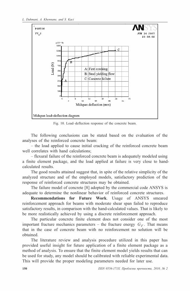
2.5. Load–Deflection Response. Load–deflection behavior of concrete
structures typically includes three stages. Stage I manifests the linear behavior of
uncracked elastic section. Stage II implies initiation of concrete cracking and
Stage III relies relatively on the yielding of steel reinforcements and the crushing
of concrete. In nonlinear iterative algorithms, ANSYS 8.0 utilizes Newton–Raphson
method for the incremental load analysis.
The full nonlinear load–deformation response is shown in Fig. 10. The
response calculated using FE analysis is plotted. The entire load–deformation
response of the model produced well correlates with the hand calculated results
(see Appendix). This gave confidence in the use of ANSYS and the model
developed.
Conclusions. Finite element models of 3.0 m ordinarily reinforced concrete
beams, constructed in ANSYS V8.0 using the dedicated concrete elements have
accurately captured the nonlinear flexural response of these systems up to failure.
The dedicated element employs a smeared crack model to allow for concrete
cracking with the option of modeling the reinforcement in a distributed or discrete
ways.
In terms of using finite element models to predict the strength of existing
beams, the assignment of appropriate material properties is critical.
ISSN 0556-171X. Ïðîáëåìû ïðî÷íîñòè, 2010, ¹ 2 149
Crack Identification in the Reinforced Concrete Beam ...
Fig. 9. Failure of the concrete beam.
The following conclusions can be stated based on the evaluation of the
analyses of the reinforced concrete beam:
– the load applied to cause initial cracking of the reinforced concrete beam
well correlates with hand calculations;
– flexural failure of the reinforced concrete beam is adequately modeled using
a finite element package, and the load applied at failure is very close to hand-
calculated results.
The good results attained suggest that, in spite of the relative simplicity of the
analyzed structure and of the employed models, satisfactory prediction of the
response of reinforced concrete structures may be obtained.
The failure model of concrete [8] adopted by the commercial code ANSYS is
adequate to determine the nonlinear behavior of reinforced concrete structures.
Recommendations for Future Work. Usage of ANSYS smeared
reinforcement approach for beams with moderate shear span failed to reproduce
satisfactory results, in comparison with the hand-calculated values. That is likely to
be more realistically achieved by using a discrete reinforcement approach.
The particular concrete finite element does not consider one of the most
important fracture mechanics parameters – the fracture energy GF . That means
that in the case of concrete beam with no reinforcement no solution will be
obtained.
The literature review and analysis procedure utilized in this paper has
provided useful insight for future application of a finite element package as a
method of analysis. To ensure that the finite element model yields results that can
be used for study, any model should be calibrated with reliable experimental data.
This will provide the proper modeling parameters needed for later use.
150 ISSN 0556-171X. Ïðîáëåìû ïðî÷íîñòè, 2010, ¹ 2
L. Dahmani, A. Khennane, and S. Kaci
Fig. 10. Load–deflection response of the concrete beam.
Appendix
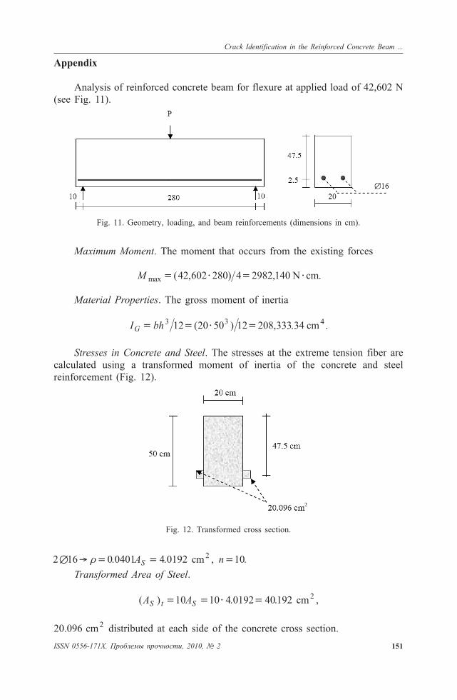
Analysis of reinforced concrete beam for flexure at applied load of 42,602 N
(see Fig. 11).
Maximum Moment. The moment that occurs from the existing forces
M max ( , ) ,� � �42 602 280 4 2982 140 N cm� .
Material Properties. The gross moment of inertia
I bhG � � � �3 312 20 50 12 208 333 34( ) , . cm4 .
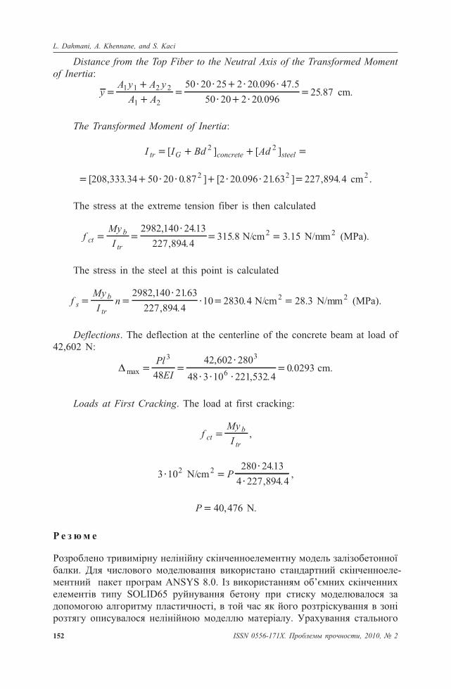
Stresses in Concrete and Steel. The stresses at the extreme tension fiber are
calculated using a transformed moment of inertia of the concrete and steel
reinforcement (Fig. 12).
2 16 0 0401 4 0192 2� � � �� . . ,AS cm n�10.
Transformed Area of Steel.
( ) . . ,A AS t S� � � �10 10 4 0192 40192 2cm
20.096 cm2 distributed at each side of the concrete cross section.
Fig. 11. Geometry, loading, and beam reinforcements (dimensions in cm).
Fig. 12. Transformed cross section.
ISSN 0556-171X. Ïðîáëåìû ïðî÷íîñòè, 2010, ¹ 2 151
Crack Identification in the Reinforced Concrete Beam ...
Distance from the Top Fiber to the Neutral Axis of the Transformed Moment
of Inertia:
yA y A y
A A�
�
� � � �
� �1 1 2 2
1 2
50 20 25 2 20 096 47 5
50 20 2 20
. .
.09625 87� . .cm
The Transformed Moment of Inertia:
I I Bd Adtr G concrete steel� �[ ] [ ]2 2
� � � � � �[ , . . ] [ . . ] ,208 333 34 50 20 0 87 2 20 096 2163 227 892 2 4 4 2. .cm
The stress at the extreme tension fiber is then calculated
fMy
Ictb
tr
� ��
�2982 140 2413
227 894 4315 8
, .
, .. N/cm2 � 3.15 N/mm2 (MPa).
The stress in the steel at this point is calculated
fMy
Ins
b
tr
� ��
� �2982 140 2163
227 894 410 2830 4
, .
, .. N/cm2 � 28.3 N/mm2 (MPa).
Deflections. The deflection at the centerline of the concrete beam at load of
42,602 N:
max
,
, ..� �
�
� � ��
Pl
EI
3 3
648
42 602 280
48 3 10 221 532 40 0293 cm.
Loads at First Cracking. The load at first cracking:
fMy
Ictb
tr
� ,
3 102� N/cm2 280 2413
4 227 894 4�
�
�P
.
, .,
P � 40 476, .N
Ð å ç þ ì å
Ðîçðîáëåíî òðèâèì³ðíó íåë³í³éíó ñê³í÷åííîåëåìåíòíó ìîäåëü çàë³çîáåòîííî¿
áàëêè. Äëÿ ÷èñëîâîãî ìîäåëþâàííÿ âèêîðèñòàíî ñòàíäàðòíèé ñê³í÷åííîåëå-
ìåíòíèé ïàêåò ïðîãðàì ANSYS 8.0. ²ç âèêîðèñòàííÿì îá’ºìíèõ ñê³í÷åííèõ
åëåìåíò³â òèïó SOLID65 ðóéíóâàííÿ áåòîíó ïðè ñòèñêó ìîäåëþâàëîñÿ çà
äîïîìîãîþ àëãîðèòìó ïëàñòè÷íîñò³, â òîé ÷àñ ÿê éîãî ðîçòð³ñêóâàííÿ â çîí³
ðîçòÿãó îïèñóâàëîñÿ íåë³í³éíîþ ìîäåëëþ ìàòåð³àëó. Óðàõóâàííÿ ñòàëüíîãî
152 ISSN 0556-171X. Ïðîáëåìû ïðî÷íîñòè, 2010, ¹ 2
L. Dahmani, A. Khennane, and S. Kaci

àðìóâàííÿ áàëêè ïðîâîäèëîñÿ äëÿ ð³çíèõ îá’ºìíèõ äîëåé ñòàë³ â áåòîí³. Äëÿ
áåòîííî¿ áàëêè áåç àðìóâàííÿ ðåçóëüòàòè ðîçðàõóíê³â çà äîïîìîãîþ ïðîãðà-
ìè ANSYS ïîð³âíþâàëèñÿ ç àíàë³òè÷íèìè ðîçðàõóíêàìè. Ïðè öüîìó îòðè-
ìàíî ¿õ õîðîøó çá³æí³ñòü. Ïîêàçàíî âèêîðèñòàííÿ ìîäåë³ äëÿ îö³íêè êðèòè÷-
íèõ çîí ðîçòð³ñêóâàííÿ, çàâàíòàæåíü ³ ïåðåì³ùåíü ó çàë³çîáåòîííèõ áàëêàõ çà
ð³çíîãî ðîäó íàâàíòàæåíü.
1. M. Y. H. Bangash, Concrete and Concrete Structures: Numerical Modeling
and Applications, Elsevier Science Publishers Ltd., London (1989).
2. Y. Hemmaty, “Modeling of the shear force transferred between cracks in
reinforced and fibre reinforced concrete structures,” in: Proc. of the ANSYS
Conf., Vol. 1, Pittsburgh, PA (1998).
3. ANSYS 8.0 Manual Set, ANSYS Inc., Canonsburg, PA (1998).
4. ANSYS Theory Reference, Seventh Edition, Swanson Analysis Systems (1998).
5. ANSYS – Engineering Analysis System. Theoretical Manual (for ANSYS
Revision 8.04), Swanson Analysis Systems (1998).
6. D. Kachlakev and T. Miller, FE Modeling of Reinforced Concrete Structures
Strengthened with FRP Lamiates, Final Report SPR 316, Oregon State
University (2001).
7. K. J. Willam, University of Colorado (Private communication) (1982).
8. K. J. William and E. D. Warnke, “Constitutive model for the triaxial behavior
of concrete,” in: Proc. of the Int. Association for Bridge and Structural
Engineering, ISMES, Bergamo (1975), Vol. 19, p. 174.
9. K. J. Bathe, Finite Element Procedures, Prentice-Hall Inc., New Jersey
(1996).
10. W. F. Chen and D. J. Han, Plasticity for Structural Engineers, Springer-
Verlag, New York (1988).
Received 12. 09. 2007
Crack Identification in the Reinforced Concrete Beam ...
ISSN 0556-171X. Ïðîáëåìû ïðî÷íîñòè, 2010, ¹ 2 153