CRAB-CAVITY BEAM DYNAMICS ISSUES FOR AN LHC UPGRADE cavities LHC... · 2008-07-24 · CRAB-CAVITY...
16
CRAB-CAVITY BEAM DYNAMICS ISSUES FOR AN LHC UPGRADE Yi-Peng Sun, Rogelio Tomas, Frank Zimmermann, AB/ABP group, CERN, Geneva Abstract Modern colliders bring into collision a large number of bunches per pulse or per turn to achieve a high luminosity. The long-range beam-beam effects arising from parasitic encounters at such colliders are mitigated by introducing a crossing angle. Under these conditions, crab cavities can be used to restore effective head-on collisions and thereby to increase the geometric luminosity. Crab cavities have been proposed for both linear and circular colliders. The crab cavities are rf cavities operated in a transverse dipole mode, which imparts on the beam particles a transverse kick that varies with the longitudinal position along the bunch. The use of crab cavities in the LHC may not only raise the luminosity, but it could also complicate the beam dynamics, e.g. crab cavities might not only cancel synchro-betatron resonances excited by the crossing angle but they could also excite new ones, they could reduce the dynamic aperture for off-momentum particles, they could degrade the collimation cleaning efficiency, and so on. In this note, we summarize the results of several preliminary studies of beam-dynamics challenges associated with crab cavities in the LHC. 1 Introduction The Large Hadron Collider (LHC), now being constructed at CERN (European Organization for Nuclear Research), will start beam commissioning in 2008. The LHC has four Interaction Points (IPs). Its design luminosity is 10 34 cm -2 s -1 at the two high-luminosity proton-proton experiments ATLAS (located at IP1) and CMS (located at IP5), with a centre-of-mass energy of 14 TeV [1]. Studies aimed to further raising the LHC luminosity are being carried out since 2001, from 2004 onwards jointly by the European CARE-HHH network and by US-LARP. These studies developed a roadmap for increasing the luminosity of LHC by a factor of 10 above its design value, to 10 35 cm -2 s -1 in the second half of the next decade. Recently, three upgrade scenarios have crystallized from various considerations. These three scenarios are called the early-separation (ES) scheme, the full crab crossing (FCC) scheme, and the Large-Piwinski angle (LPA) scheme [2]. For the ES and FCC approaches, crab cavities are an essential ingredient of the upgrade. As usual, the crab cavities will render the effective Piwinski angle equal to zero, and minimize the geometric luminosity loss which otherwise arises from the crossing angle. By contrast, the LPA scheme relies on a non-zero Piwinski angle. It could only make use of crab cavities if the latter do not restore the beam-beam tune shift to the value obtained for a head-on collision. The crab cavity gives rise to a z-dependent horizontal or vertical kick on the beam particles (depending in the crossing plane), as well as to a change in the longitudinal momentum (or energy). In MAD coordinates, the Hamiltonian to describe the “thin” crab cavity is [3] 1 3 sin ˆ x c x p V q H s s crab ⋅ ⎟ ⎠ ⎞ ⎜ ⎝ ⎛ + = ω φ (1) where, H crab denotes the Hamiltonian, V the crab-cavity voltage, q the particle charge, p s the momentum of particle, φ s the “synchronous” phase of the crab cavity rf wave, ω the angular frequency of the crab cavity, c the velocity of light, x 1 the horizontal coordinate (x) and x 3 the longitudinal coordinate (z), respectively. 1
Transcript of CRAB-CAVITY BEAM DYNAMICS ISSUES FOR AN LHC UPGRADE cavities LHC... · 2008-07-24 · CRAB-CAVITY...

CRAB-CAVITY BEAM DYNAMICS ISSUES FOR AN LHC UPGRADE
Yi-Peng Sun, Rogelio Tomas, Frank Zimmermann, AB/ABP group, CERN, Geneva
Abstract Modern colliders bring into collision a large number of bunches per pulse or per turn to achieve a high luminosity.
The long-range beam-beam effects arising from parasitic encounters at such colliders are mitigated by introducing a
crossing angle. Under these conditions, crab cavities can be used to restore effective head-on collisions and thereby to
increase the geometric luminosity. Crab cavities have been proposed for both linear and circular colliders. The crab
cavities are rf cavities operated in a transverse dipole mode, which imparts on the beam particles a transverse kick that
varies with the longitudinal position along the bunch. The use of crab cavities in the LHC may not only raise the
luminosity, but it could also complicate the beam dynamics, e.g. crab cavities might not only cancel synchro-betatron
resonances excited by the crossing angle but they could also excite new ones, they could reduce the dynamic aperture
for off-momentum particles, they could degrade the collimation cleaning efficiency, and so on. In this note, we
summarize the results of several preliminary studies of beam-dynamics challenges associated with crab cavities in the
LHC.
1 Introduction The Large Hadron Collider (LHC), now being constructed at CERN (European Organization for Nuclear
Research), will start beam commissioning in 2008. The LHC has four Interaction Points (IPs). Its design luminosity is
1034 cm-2s-1 at the two high-luminosity proton-proton experiments ATLAS (located at IP1) and CMS (located at IP5),
with a centre-of-mass energy of 14 TeV [1]. Studies aimed to further raising the LHC luminosity are being carried out
since 2001, from 2004 onwards jointly by the European CARE-HHH network and by US-LARP. These studies
developed a roadmap for increasing the luminosity of LHC by a factor of 10 above its design value, to 1035 cm-2s-1 in
the second half of the next decade. Recently, three upgrade scenarios have crystallized from various considerations.
These three scenarios are called the early-separation (ES) scheme, the full crab crossing (FCC) scheme, and the
Large-Piwinski angle (LPA) scheme [2]. For the ES and FCC approaches, crab cavities are an essential ingredient of the
upgrade. As usual, the crab cavities will render the effective Piwinski angle equal to zero, and minimize the geometric
luminosity loss which otherwise arises from the crossing angle. By contrast, the LPA scheme relies on a non-zero
Piwinski angle. It could only make use of crab cavities if the latter do not restore the beam-beam tune shift to the value
obtained for a head-on collision.
The crab cavity gives rise to a z-dependent horizontal or vertical kick on the beam particles (depending in the
crossing plane), as well as to a change in the longitudinal momentum (or energy). In MAD coordinates, the Hamiltonian
to describe the “thin” crab cavity is [3]
13sin
ˆx
cx
pVqH ss
crab ⋅⎟⎠⎞
⎜⎝⎛ +=
ωφ (1)
where, Hcrab denotes the Hamiltonian, V the crab-cavity voltage, q the particle charge, ps the momentum of particle, φs
the “synchronous” phase of the crab cavity rf wave, ω the angular frequency of the crab cavity, c the velocity of light, x1
the horizontal coordinate (x) and x3 the longitudinal coordinate (z), respectively.
1
The horizontal and longitudinal kicks from the crab cavity can be written as:
⎟⎠⎞
⎜⎝⎛ +−=
∂∂
−=Δcx
pVq
xHp s
s
crab 3
11 sin
ˆ ωφ (2)
13
33 cos
ˆx
ccx
pVq
xHp s
s
crab ⋅⎟⎠⎞
⎜⎝⎛⋅⎟
⎠⎞
⎜⎝⎛ +−=
∂∂
−=Δωωφ (3)
In circular colliders, crab cavities may be configured according to either one of two schemes, namely as “local” or
“global” crab cavities. In the local scheme, which corresponds to the original classical proposals of Palmer, Oide and
Yokoya, a pair of crab cavities is placed at both sides of one IP, with the phase advance between crab cavity and IP
optimized to be π/2 in the crossing plane; in that case, for each value of z the crab cavities act like a local bump and the
z-dependent closed orbit in the other parts of the ring is not affected. The voltage needed for the first crab cavity (to
“rotate” the bunch so as to be head-on at the interaction point) and for the second crab cavity (to rotate the bunch back)
can be calculated using the formulae (4) and (5) below [4]. For the global scheme, the crab cavity is located somewhere
around the ring, at a place which satisfies certain phase advance requirements which involve the total betatron tune in
addition to the phase advance from crab cavity to the IP; in the global case, the z-dependent closed orbit will be changed
all around the ring with crab cavity active, and the crab cavity voltage for the global scheme can be calculated from
formula (6) below [4]. The bunch will be “tilted” and the tilt will exhibit some kind of oscillation all around the ring
such that at the interaction point it will be head-on. The global scheme is the one which has actually been implemented
at KEKB [5].
The rf voltage required for the two local crab cavities installed around one IP are determined as
( )( )ϕββω
θΔ⋅⋅
⋅⋅=
sin2/tan
*1
crab
EcV (4)
1222 VRV ⋅−= (5)
where V1 denotes the voltage of the first crab cavity, V2 the voltage of the second crab cavity, E the particle energy, θ
the full crossing angle at the IP, β* the beta function at the IP, βcrab the beta function at the crab cavity location, and Δφ
the phase advance between the IP and the first crab cavity. Lastly, R22 signifies the (2,2) element of the optical transport
matrix from the first crab cavity to the second crab cavity.
The rf voltage for the global crab cavity is given by
( ) ( )( )Q
QEcVcrab
πϕπ
ββωθ
−Δ⋅
⋅
⋅⋅=
cossin22/tan
* (6)
where V designates the voltage of the global crab cavity, and Q the betatron tune.
In the following, we will study the beam dynamics associated with the presence of a crab cavity for two kinds of
LHC optics: the “nominal” LHC optics and the so-called “low-beta-max” optics [6]. Relevant parameters of these two
optics are listed in Table 1. Both optics are studied for a beam at top energy. If not specifically mentioned, the nominal
LHC optics and beam 1 are considered.
2

Table 1: Relevant parameters of the two LHC optics under study
parameter symbol nominal LHC optics low-beta-max optics
protons per bunch Nb [1011] 1.15 1.15
rms bunch length σz [cm] 7.55 7.55
rms energy spread σe [10-4] 1.1 1.1
beta function at IP1&5 β* [m] 0.55 0.25
emittance Ε [10-6 m] 3.75 3.75
full crossing angle θc [μrad] 285 381
horizontal beta function at s=0 βx [m] 41 40
vertical beta function at s=0 βy [m] 356 408
2 Horizontal crossing at IP5 In the LHC, the beams cross horizontally at IP5 and vertically at IP1. In this section we will consider the horizontal
crossing case at IP5 only. Both the global crab cavity scheme and the local crab cavity scheme will be studied. This
followed by some preliminary results of luminosity simulations with the code GUINEA-PIG and by a first assessment
of the impact of crab cavities on the performance of the collimation system. In Section 3 the case of a vertical crossing
at IP5 (for the real LHC the vertical crossing will be at IP1) will be examined. In all studies of this note, the starting
point of the LHC sequence will be IP3, and tracking is performed with the well known-code SixTrack, which is the
work horse of dynamic aperture studies at the LHC.
2.1 Global crab cavity for the nominal LHC optics
The location of the global crab cavity is selected to be upstream of IP5, outside D2, between Q4 and Q5. We
selected the location there as beams 1 and 2 have reached their full arc separation and for local crab cavity case, to be
studied afterwards, the phase advance to IP5 is near π/2 (the location of the global crab cavity is here taken to be the
same as the first cavity location of the local crab cavity case; in reality the global cavity would more likely be installed
in IR4 where the separation between the two beams is largest and cryogenics plus other needed infrastructure might be
more easily available). The longitudinal distance between the selected position and IP5 is around 170~171 m, and the
horizontal phase advance between IP5 and the global crab cavity is around 0.23~0.25. The detailed parameters of IP5
and of the crab cavity location are listed in Table 2. Using formulae (6), the voltage for an 800-MHz crab cavity is
calculated to be 11.9087 MV. For 400-MHz cavity, the voltage value needs to be doubled.
Table 2: Parameters at IP5 and at the location of the global crab cavity
Longitudinal S [m] βx [m] βy [m] Phase advance x Phase advance y
IP5 6664.6 0.55 0.55 15.4716 14.5941
crab cavity 6835.2 258 1547 15.7496 14.8553
Figure 1 shows the simulated longitudinal-horizontal bunch distribution at IP5 for three cases: with an 800-MHz
crab cavity (CC), for a 400-MHz crab cavity, and assuming a totally linear kick crab cavity RF slope. From this figure it
can be inferred that the linearity of the 400-MHz crab cavity is much better than that of the 800-MHz cavity. However,
3

the cavity size will be much larger for the 400-MHz cavity, which may make it difficult install such cavity on the beam
line in the LHC tunnel.
Figure 1: Bunch distribution at IP5 with global crab cavity
A sufficiently large dynamic aperture is important for achieving a good beam life time and a high integrated
luminosity. Here we track two twin particles over 100,000 turns in SixTrack, to determine the minimum dynamic
aperture. The beam-beam effect has not been taken into account. The initial relative momentum offset is set to 0.00027
(3/4 of the rf bucket; standard convention for all LHC dynamic-aperture studies). The results are shown in Fig. 2, which
demonstrates that the 800-MHz crab cavity provides for a better dynamic aperture than the 400-MHz cavity. However,
this need not always be true. A comparison of different cases will be shown in the following sections.
Figure 2: Dynamic aperture for the nominal LHC optics
4

For the purpose of our study, 168 BPMs are placed in the nominal LHC optics sequence file with equal physical
separation between successive BPM elements. Then one particle with zero initial horizontal and vertical offset, and with
energy offsets equal to 1, 2, 3 sigma are tracked for 1000 turns respectively. The horizontal peak to peak orbit is
extracted from each set of BPM data and plotted in Figs. 3, 4 and 5. Comparing these three cases it shows that the
400-MHz global crab cavity introduces the largest disturbance of the horizontal orbit, while the 800-MHz case is much
improved. The impact on the collimation system will be preliminarily analyzed in the following sections. The
performances of the global crab cavity and the local crab cavity scheme will also be compared later.
Figure 3: Horizontal peak-to-peak orbit for the nominal LHC optics without crab cavity for various momentum offsets
Figure 4: Horizontal peak-to-peak orbit for the nominal LHC optics with an 800-MHz global crab cavity for various
initial momentum offsets
5

Figure 5: Horizontal peak-to-peak orbit for the nominal LHC optics with a 400-MHz global crab cavity for various
initial momentum offsets
In Figure 5, there are two peaks, in IR5 (the first peak) and in IR1 (the second peak). They are due to the closed
orbit disturbance induced by the crab cavities and the physics behind remains to be studied in detail.
Synchrobetatron resonances are caused by different transverse beam-beam forces at different longitudinal positions
(synchrotron oscillation modulation) in the colliding bunches, an effect which is introduced by the transverse crossing
angle at IP [7]. It was suggested that crab cavities could eliminate this kind of resonance for circular colliders. (It was
also predicted – long ago - that crab-cavities could restore an effective head-on collision at the IP for both linear
colliders [8] and circular colliders [9].) Here, without beam-beam effects, we simply compute the FFT of simulated
BPM data by using the SUSSIX code, to obtain the spectrum shown in Fig. 6. A particle is tracked for 10,000 turns to
minimize the influence of noise on the FFT results. Both the horizontal initial offset and the longitudinal initial offset
are set to be one sigma. A detailed complementary study including beam-beam force is still ongoing. Three cases will
be compared, namely only the “head-on” beam-beam effects with a crossing angle, the beam beam effects plus a crab
cavity, and only crab cavity without beam-beam. We expect to see that for the case with beam-beam effects plus crab
cavity the synchrobetatron resonance strength is the lowest.
Figure 6: Comparison of synchrobetatron sidebands with two different global crab cavities and without any crab cavity
for the nominal LHC optics; no beam-beam effects are included
6

To render the comparison without beam-beam effect clearer, in Fig. 6 the frequency of the 800-MHz global crab
cavity case was shifted downward by -0.0005 tune units, and that for the 400-MHz case by -0.001 tune units. In Fig. 6 it
can be seen that the fractional part of the horizontal tune is equal to 0.31 from the FFT, and the fractional part of the
vertical tune equals 0.32, which are just the official tunes for the nominal LHC optics at top energy. Also, the
amplitudes of the synchrobetatron resonances are larger with crab cavity than for the case with no crab cavity,
especially considering higher order sidebands, which represent synchrobetatron resonances excited by the crab cavity.
These resonances are generated because the crab cavity exerts a z-dependent horizontal kick on the particles, which is
similar to the beam-beam crossing effect at the IP (and which should partially cancel the latter).
2.2 Local crab cavity for nominal LHC optics
For the local crab cavities, the location of the first crab cavity is chosen at exactly the same place as for the global
crab cavity. We recall that this location is found upstream of IP5, outside D2, and between Q4 and Q5. The second crab
cavity is placed symmetrically at the other side of the IP5. Relevant parameters are listed in Table 3.
Table 3 Parameters at IP5 and at local crab cavities
Longitudinal S [m] βx [m] βy [m] Phase advance x Phase advance y
Crab cavity 1 6493.9 1523 255 15.2225 14.3283
IP5 6664.6 0.55 0.55 15.4716 14.5941
Crab cavity 2 6835.2 258 1547 15.7496 14.8553
Applying formulae (4) and (5), and also using the transfer matrix from crab cavity 1 to crab cavity 2, the 800-MHz
cavity voltages are calculated to be 5.1051 MV and 2.6751 MV for the two cavities, respectively. Similar to Fig. 1, the
simulated longitudinal-horizontal bunch distribution for the local crab cavity case is benchmarked with the linear kick
model, in Fig. 7. Again the 400-MHz case clearly reveals a better linearity. Following the same analysis procedures as
in Section 2.1, here we simply present the results for the dynamic aperture, for the horizontal peak-to-peak orbit, and for
synchrobetatron sidebands, in Figs. 8, 9 and 10, respectively.
Figure 7: Bunch distribution at IP5 with local crab cavities
7

Figure 8: Dynamic aperture for the nominal LHC optics with local crab cavities
Figure 9: Horizontal peak-to-peak orbit for the nominal LHC optics with local crab cavities operating at 800 MHz (left)
or 400 MHz (right).
Figure 10: Comparison of synchrobetatron sidebands for the nominal LHC optics with local crab cavities
8

For the local crab cavity case, the dynamic aperture is much better than for the global crab cavities, at maximum
1~2 sigma degradation compared to the case without crab cavity. Figure 9 confirms that local crab cavities do not affect
the closed orbit around the ring. Figure 10 shows more clearly that the amplitude of each sideband for these three cases
is almost the same, which is different from the situation in Fig. 6 (the frequency shift added for plotting purposes is the
same as in Figure 6).
2.3 Global crab cavity for the low-beta-max optics
For the low-beta-max optics, the crab cavities are placed at similar locations as for the nominal LHC optics, and
the results we get are indeed also quite similar to the corresponding results for the nominal LHC optics. So we only
briefly introduce the exact location of crab cavity and the other associated parameters. The location of the global crab
cavity is selected to be upstream of IP5, outside D2, and between Q4 and Q5. The detailed parameters of IP5 and of the
crab cavity location are listed in Table 4. Using formulae (6), the voltage for 800-MHz crab cavity is calculated to be
9.468 MV.
Table 4: Parameters at IP5 and at the location of the global crab cavity for the low-beta-max optics
longitudinal S [m] βx [m] βy [m] phase advance x phase advance y
IP5 6664.6 0.25 0.25 15.6213 14.367
crab cavity 6835.7 1023 2685 15.86 14.5988
It is interesting to mention that for the low-beta-max optics, the horizontal peak-to-peak orbit exhibits four maxima
around the ring, namely in the two triplets at both sides of IP1 and IP5.
2.4 Local crab cavities for the low-beta-max optics
The local crab cavity locations are also similar to those for the nominal LHC optics case. Some details are listed in
Table 5, and the 800-MHz cavity voltages for crab cavity 1 and crab cavity 2 are calculated to be 4.9568 MV and
3.1006 MV, respectively.
Table 5: Parameters at IP5 and at the locations of the local crab cavities for the low-beta-max optics
Longitudinal S [m] βx [m] βy [m] Phase advance x Phase advance y
Crab cavity 1 6493.4 2616.8 1079.6 15.3511 14.0901
IP5 6664.6 0.25 0.25 15.6213 14.367
Crab cavity 2 6835.7 1023 2685 15.86 14.5988
2.5 Comparison of dynamic aperture and beta-beating
The tracking conditions are the same as those in Section 2.1. Beam beam elements are added in the sequence file
of Beam 2 with several longitudinal slices. At IP1 and IP5, both head-on and parasitic collisions are included. At IP2
and IP8, only head-on collisions are taken into account. The particles are tracked for 100,000 turns using SixTrack, with
two error seeds. The minimum dynamic aperture for different conditions is listed in Table 6.
9
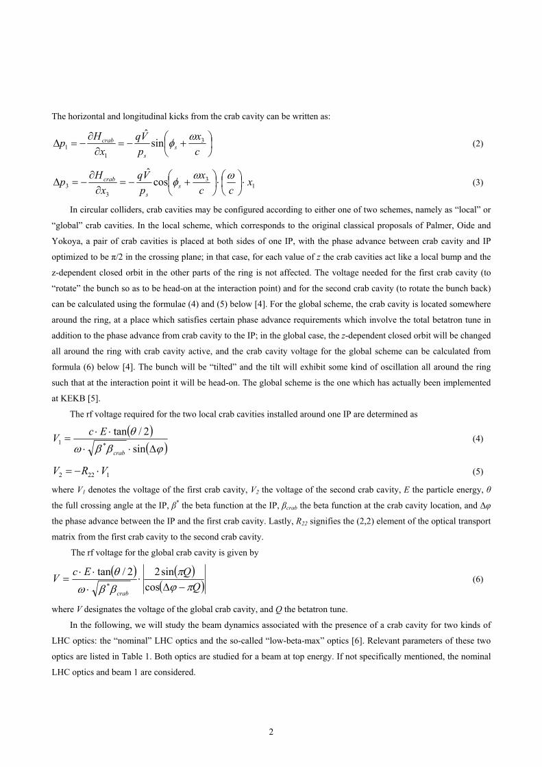
Table 6: Minimum dynamic aperture for different cases
Case Nominal LHC optics [sigma] Lowbetamax [sigma]
No beam-beam, No CC 16 15.9
Beam-beam (BB) 8.2 13
Global CC 800 (400) MHz 13 (12.1) 12.4 (14.3)
Global CC 800 (400) MHz + BB
Local CC 800 (400) MHz 14.7 (14.1) 16 (15.5)
Local CC 800 (400) MHz + BB
The off-momentum beta beating is widely studied in LHC, as it is very important for the collimation system, and
the safe operation of the superconducting ring. Figure 11 compares the off-momentum beta beating for the nominal
LHC optics and for the low-beta-max optics used in our study. It can be seen that for the nominal LHC optics, the tune
is optimized for minimum off-momentum beta beating in the region between IP1 to IP5, while for the low-beta-max
optics, which has a larger beating, it is the contrary.
Figure 11: Off-momentum beta beating for the nominal LHC optics (left) and for the low-beta-max optics (right) with a
relative momentum offset of 0.00027
Crab cavities introduce another kind of beta beating, which depends on the longitudinal position inside the bunch.
Here we consider the global 800-MHz crab cavity cases discussed earlier in Sections 2.1 and 2.3. The effect of the crab
cavity is modelled by adding a horizontal corrector (with z-dependent strength) at the location of the crab cavity in
SIXTRACK. With this trick we can study this new kind of beta beating for a particle with one sigma longitudinal offset.
According to the results shown in Fig. 12, the additional beta beating caused by the crab cavity is comparatively small
with respect to the existing off-momentum beta beating. For the nominal LHC optics, it is less than ±0.004.
10

Figure 12: z-dependent “beta beating” due to the global crab cavity for the nominal LHC optics (left) and for the
low-beta-max optics (right)
2.6 Luminosity simulation (IP1 or IP5) with GUINEA-PIG
GUINEA-PIG is a computer code for simulating the luminosity of electron-positron colliders [10]. Here we apply
this code to a storage ring, in order to simulate the single-bunch geometric luminosity at the LHC. The total luminosity
can then be calculated by multiplying with the bunch number 2808. For the LHC optics without crab cavity, two
bunches at the IP1 or IP5, each consisting of 10,000 macro-particles, are generated with a Gaussian distribution in all
six phase-space coordinates (x, x’, y, y’, ct, Δp). The rms values for the Gaussian distributions are calculated from the
design beam emittance, the design beam energy and the design beta functions at IP. It should be mentioned here that, as
the proton bunches are much larger than the typical electron bunches in linear colliders, the “cut beam size” should be
set to a large enough value in the code file “acc.dat”. To make the tracking results converge better, the longitudinal slice
number of the bunch (“n_z” in the code) is chosen to be larger than for linear-collider simulations, say equal to 200. For
the case with crab cavity, we assume that the phase advance between crab cavity and IP is exactly π/2, so that α=0 at
both the IP and at the crab-cavity location. Then, applying formula (2), a horizontal kick from the crab cavity is added
for each particle and a new bunch distribution is obtained. Two example distributions in 3-D and 2-D at the IP are
displayed in Figs. 13 and 14, respectively.
Figure 13: Distribution of the two colliding bunches for the nominal LHC without crab cavity (left) and with an
additional 800-MHz crab cavity (right)
11

Figure 14: Bunch distribution for the nominal LHC optics (left) and for the low-beta-max optics (right) without crab
cavity (red), with a 400-MHz crab cavity (green), and with an 800-MHz crab cavity (blue).
Simulation results for the LHC luminosity under different conditions are compiled in Table 7. For the nominal
LHC optics without crab cavity, the simulated luminosity is in good agreement with the design value. A fictitious
20-MHz crab cavity is used to check the correctness of the transverse kick from the crab cavity. In the near future, more
seeds will be simulated to determine the average luminosity with reduced error. A more precise tracking with the real
optics parameters will be done later.
Table 7: LHC luminosity from GUINEA-PIG
nominal LHC optics [cm-2s-1] low-beta-max [cm-2s-1]
design (from LHC design report) 1.00E+34
head-on collision 1.18E+34 2.5596E+34
normal crossing 1.00256E+34 1.50118E+34
crossing with local 20-MHz CC 1.1796E+34 2.4899E+34
crossing with local 400-MHz CC 1.1716E+34 2.42838E+34
crossing with local 800-MHz CC 1.1144E+34 2.146E+34
At the same time, we study the luminosity formulae with crab cavity analytically, to compare with the simulation
results of GUINEA-PIG. We start from the original formulae shown in [11], where the bunch distribution is assumed to
ian in l nal direction and also in the plane of the crossing angle, namely be Gauss the ongitudi
√
√
(7)
(8)
In comparison with the treatment in [11], here a more appropriate expression of the particles’ coordinates is used,
to correctly describe the kick from the crab cavity. Taking the rf sinusoidal wave shape of the crab cavity into account,
and neglecting the x’ dependent change of the particle energy (also assuming R22=0), the coordinates of the two
llid e written
12
co ing beams can b as
(9)

(10)
(11)
(12)
where θc denotes the crossing angle, c the velocity of light, and kcr=2πfcrab/c the rf wave number of crab cavity.
Writing the luminosity without crossing angle as
(13)
with Nb the number of particles inside a bunch, frev the revolution frequency, nb the total number of bunches, σx the
horizontal bunch size at IP, and σy the vertical bunch size at IP, the luminosity with finite crossing angle can be
( e expressed n glecting the hourglass effect) as
√ (14)
Using formulae (7)~(12) and formula (14), the luminosity reduction factor in comparison with the head-on
ion ca acollis se can be expressed s
·
·· ·
·· 2 4 · 2 · 2 ·
8 · · · · · 4 · · · · (15)
Then we perform the numerical integration, using Mathematica, over s in the range between minus infinity and
plus infinity, and over t in the range between minus 5σz and plus 5σz, for two cases (400-MHz crab cavity and 800-MHz
crab cavity) respectively. In Figure 15, the results from the analytical luminosity formula are presented by the four
curves. Some simulation results from GUINEA-PIG are superimposed with dots. A good agreement between the
analytical calculation and the Guinea-Pig simulation is found.
Figure 15: Normalized luminosity from analytical formulae (curves) and GUINEA-PIG simulations (dots)
13

2.7 Estimated impact on collimation system
LHC will run with super-conducting magnets and super-conducting RF cavities. Considering the huge beam power,
a tiny loss of beam particles would result in a quench and may even damage the accelerator. The LHC collimation
system is designed to protect the accelerator and to absorb the beam halo outside of a specified transverse beam size.
There are two main regions where LHC collimators are concentrated: IR3 (momentum cleaning) and IR7 (betatron
cleaning). Several kinds of collimators exist in the LHC. Among these the two main groups are the primary collimators
and the secondary collimators. The difference between the jaw opening of the primary and secondary collimators is one
beam sigma. Given the condition that the secondary collimators should never be hit by the primary beam halo, the
closed orbit shall be strictly controlled in order to set the right jaw opening of collimators. As the global crab cavity
could change the particle’s z-dependent closed orbit, it will be interesting to see how the crab cavity will affect the
collimation system, especially the difference of the closed orbit between the primary collimator and the next (or a few)
secondary collimator(s). Here, some preliminary estimation results will be reported on the crab cavity impact on the
collimation system. A more detailed study, addressing loss maps along the ring, heat deposition and collimation
inefficiencies will be performed with the help of the collimation team.
Figure 16 shows the closed orbit at different z offsets for the nominal LHC optics with the 800-MHz global crab
cavity introduced in Section 2.1. Single particles with zero transverse offset and only longitudinal z offset are tracked to
get their closed orbit, again replacing the crab cavity by a horizontal corrector with the equivalent kick.
Figure 16: Closed orbit induced by the crab cavity
This closed orbit is checked against tracking results obtained with a real crab cavity in the sequence file. In the
second case, a particle with the same initial condition as before is tracked for 1000 turns without the main RF so that the
particle’s longitudinal coordinate is approximately frozen. The horizontal position of this particle at each collimator for
each turn is plotted together with the closed orbit ( shown in Figure 16) at that collimator, in Fig. 17. The longitudinal
position of this particle at the crab cavity location is checked to be nearly constant over this number of turns, and the
energy change is seen to increase linearly with the number of turns. Figure 17 illustrates the case of one particle with
zero transverse offset and 1 sigma longitudinal offset. Other cases are similar.
14

Figure 17: Comparison between closed orbit for a static corrector and oscillation average with real crab cavity
If this particle is launched also with a nonzero initial horizontal offset, this latter offset only adds to the amplitude
of the betatron oscillations while the average value should still be the closed orbit shown in Fig. 16. Figure 18 confirms
that this is the case.
Figure 18: Comparison between closed orbit and oscillation (including betatron oscillation)
3 Vertical crossing at IP5
For the purpose of illustration, we assume to have a vertical beam crossing at IP5 (with the same crossing angle as
for the horizontal case), and repeat the work done in Section 2. The locations of the global and local crab cavities are
chosen exactly the same as for the horizontal crossing case. Here we just list the crab cavity voltage and the dynamic
aperture tracking results. In Table 8 the required crab cavity voltage is listed, for the 285 micro-radian vertical crossing
angle of the nominal LHC optics and a crossing angle of 381 micro-radians for the low-beta-max optics.
Table 8: Crab cavity voltage for different cases
nominal LHC optics [MV] low-beta-max optics [MV]
Global-800 MHz crab cavity 4.3283 5.8016
local 800-MHz, crab cavity one 2.0675 3.1122
local 800-MHz, crab cavity two 6.568 4.9087
15

16
Table 9 lists the results of dynamic-aperture studies for the cases with vertical crab cavities. The tracking
conditions are the same as those described in Section 2.1.
Table 9: Minimum dynamic aperture for different cases
case nominal LHC optics [sigma] low-beta-max [sigma]
no beam-beam, no CC 16 15.9
Global CC 800 (400) MHz 14.2 (13.9) 12.7 (14)
local CC 800 (400) MHz 14.1 (14) 15.5 (16)
Comments
As a next step, some items discussed in this note should be explored in greater detail, such as the impact of crab
cavities on the collimation system, and the interplay of a crab cavity with beam-beam effects (tune shift,
synchrobetatron oscillations, luminosity). Also, a specific realistic location for a global crab cavity must be selected,
probably in IR4, and the LHC optics may need to be adjusted for smaller crab cavity voltage (e.g. higher beta function
at the crab cavity) and for a better performance with crab cavity.
Acknowledgement
The authors would like to thank Dr. Daniel Schulte for providing the simulation code GUINEA-PIG. The authors
would also like to thank Dr. Ralph Assmann, and Dr. Rama Calaga for helpful discussions, and Drs. M. Giovannozzi,
Dr. F. Schmidt, U. Dorda for their comments. The author Y. P. Sun would like to thank P. Letnes for the help on
software.
This work was supported by the European Community-Research Infrastructure Activity under the FP6 “Structuring
the European Research Area” programme (CARE, contract number RII3-CT-2003-506395).
References
[1]. LHC Design Report Volume one, the LHC Main Ring, CERN 2004-003.
[2]. Frank Zimmermann, in Proceedings of Particle Accelerator Conference 2007, page 714.
[3]. Ulrich Dorda, private communication, 2007.
[4]. Frank Zimmermann, private communication, 2007.
[5]. K.Oide et al., in Proceedings of Particle Accelerator Conference 2007, page 27.
[6]. O. Bruning, R. De Maria, R. Ostijic, Low Gradient, Large Aperture IR Upgrade Options for the LHC
compatible with Nb-Ti Magnet Technology, LHC Project Report 1008 (2007).
[7]. A. Piwinski, IEEE Trans. Nucl. Sci. 24, 1480 (1977).
[8]. R. Palmer, SLAC Report No. SLAC-PUB-4707, 1988.
[9]. K. Oide and K. Yokoya, Phys. Rev. A 40, 315 (1989).
[10]. D. Schulte, PhD thesis, dissertation at University Hamburg, 1996.
[11]. F. Zimmermann and U. Dorda, Progress of Beam-Beam Compensation Schemes, in Proceedings of
LHC-LUMI-05 Workshop, Arcidosso, Italy (2005).


![HOM Coupler Alterations for the LHC DQW Crab Cavity[3] B. Muratoriand T. Pieloni, “Luminosity Levelling techniques for the LHC", (CERN, Geneva, Switzerland), pp. 177–181, Proceedings,](https://static.fdocuments.us/doc/165x107/5f1088927e708231d4499462/hom-coupler-alterations-for-the-lhc-dqw-crab-cavity-3-b-muratoriand-t-pieloni.jpg)