CPU-1232 & CPU-1432: Windows CE - Eurotech
26
EmbeddedDNA ® PC/104 CPU Module An0050 CPU-1x32; Windows CE Rev. 1.0 April 2005 COPYRIGHT 1994-2005 Eurotech S.p.A. All Rights Reserved.
Transcript of CPU-1232 & CPU-1432: Windows CE - Eurotech

EmbeddedDNA ®
PC
CPU-1
Rev. 1.0
COPYRIGHT 1994-
/104 CPU Module An0050
x32; Windows CE
April 2005
2005 Eurotech S.p.A. All Rights Reserved.

Application Note 2
Via J. Linussio 1 33020 AMARO (UD)
ITALY Phone: +39 0433 485 411 Fax: +39 0433 485 499
Web: http://www.eurotech.it
E-mail: mailto:[email protected]
NOTICE
Although all the information contained herein has been carefully verified, Eurotech S.p.A. assumes no responsibility for errors that might appear in this document, or for damage to property or persons resulting from an improper use of this manual and of the related software. Eurotech S.p.A. reserves the right to change the contents and form of this document, as well as the features and specifications of its products at any time, without notice. Trademarks and registered trademarks appearing in this document are the property of their respective owners

Application Note 3
Contents
Contents ........................................................................................................................................................... 3 Conventions ................................................................................................................................................... 4 Introduction .................................................................................................................................................... 5
Chapter 1 Creating a Bootloader disc for Windows CE .......................................................................... 6 Chapter 2 Install & configure the Ethernet adaptor ................................................................................. 8 Chapter 3 Connecting a Terminal Emulator ........................................................................................... 10 Chapter 4 BIOS Settings ........................................................................................................................... 14 Chapter 5 Boot With Ethernet Procedure ............................................................................................... 16
Initial Requirements:.............................................................................................................................. 17 Set-up Procedure: ................................................................................................................................. 18
Chapter 6 Configuring a stand-alone system......................................................................................... 22 Chapter 7 Frequently asked questions ................................................................................................... 24 Where to find us............................................................................................................................................. 25

Application Note 4
Conventions
The following table lists conventions used throughout this guide.
Icon Notice Type Description
Information note Important features or
instructions
Warning
Information to alert you to potential damage to a program, system or device or potential personal injury
Application Note 5
Introduction
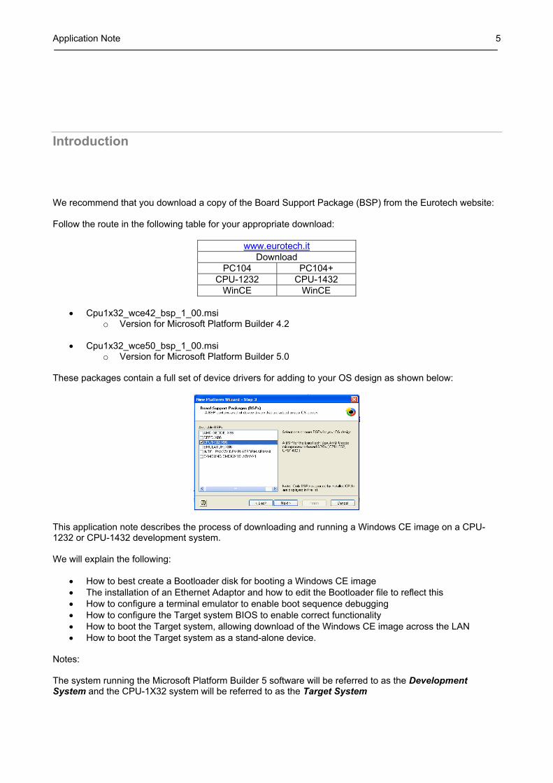
We recommend that you download a copy of the Board Support Package (BSP) from the Eurotech website: Follow the route in the following table for your appropriate download:
www.eurotech.it Download
PC104 PC104+ CPU-1232 CPU-1432
WinCE WinCE
• Cpu1x32_wce42_bsp_1_00.msi o Version for Microsoft Platform Builder 4.2
• Cpu1x32_wce50_bsp_1_00.msi
o Version for Microsoft Platform Builder 5.0 These packages contain a full set of device drivers for adding to your OS design as shown below:
This application note describes the process of downloading and running a Windows CE image on a CPU-1232 or CPU-1432 development system. We will explain the following:
• How to best create a Bootloader disk for booting a Windows CE image • The installation of an Ethernet Adaptor and how to edit the Bootloader file to reflect this • How to configure a terminal emulator to enable boot sequence debugging • How to configure the Target system BIOS to enable correct functionality • How to boot the Target system, allowing download of the Windows CE image across the LAN • How to boot the Target system as a stand-alone device.
Notes: The system running the Microsoft Platform Builder 5 software will be referred to as the Development System and the CPU-1X32 system will be referred to as the Target System

Application Note 6
Chapter 1 Creating a Bootloader disc for Windows CE
The Windows CE Bootloader Disk will give the operator several options for booting their Target system; a menu will appear on the Target system during the boot sequence, all the options are listed below:
1. CEPC_LOCAL, Boot CE/PC (local NK.BIN)
Boot the Target system using the NK.BIN image stored on the boot device.
2. CEPC_1024, Boot CE/PC (ether via eboot.bin with /L: 1024x768x8) Boot the Target system using the Windows CE image currently in use on the
development system. Transfer is managed across the LAN. Screen resolution is set to 1024 pixels x 768 Pixels with 8 colours.
3. CEPC_800, Boot CE/PC (ether via eboot.bin with /L: 800x600x16)
Boot the Target system using the Windows CE image currently in use on the development system.
Transfer is managed across the LAN. Screen resolution is set to 800 pixels x 600 Pixels with 16 colours.
4. CEPC_640, Boot CE/PC (ether via eboot.bin with /L: 640x480x32)
Boot the Target system using the Windows CE image currently in use on the development system.
Transfer is managed across the LAN. Screen resolution is set to 640 pixels x 480 Pixels with 32 colours.
5. CEPC_SERIAL, Boot CE/PC (serial via sboot.bin)
NOTE: this Application note does not cover this option. Boot the Target system using the Windows CE image currently in use on the
development system. Transfer is managed across a Serial connection.
6. VESATEST, Run Vesa Test program and list valid display modes.
Vesa Test programme is run and lists available display modes.
7. CLEAN, Clean Boot (no commands) The Target system boots to the operating system on the Bootloader disc

Application Note 7
We suggest three possible methods for creating a Windows CE/PC boot disc: Method 1:
Use the CEPCBOOT.144 disk image (Part of the Windows Platform Builder Installation). Note: The following is an abstract from a Microsoft Windows readme.txt file found with the Windows Platform Builder 5 Documentation Install the websetup application (note that this only needs to be done once) by executing
websetup.exe in %CEPBDir%\cepb\utilities. Once websetup is installed, “executing” cepcboot.144 (either by running “cepcboot.144” from
the command line or double clicking on the cepcboot.144 icon in File Explorer) will start the websetup application.
Insert a floppy disk in the drive and follow the on-screen instructions to create a CE/PC Bootloader disk.
Method 2:
Create a bootable MS-DOS disk by following the instructions that came with your MS-DOS version. Note: The following is an abstract from a Microsoft Windows readme.txt file found with the Windows Platform Builder 5 Documentation Copy himem.sys from your MS-DOS distribution to the boot floppy Copy all the Bootloader disk files from the
%_WINCEROOT%\public\common\oak\csp\i486\dos\bootdisk directory. Optionally copy the Ethernet Bootloader (eboot.bin) or serial Bootloader (sboot.bin) images
from a recent CE/PC build to the disk (this would only be necessary if you’ve updated the loader code).
Method 3:
Create a bootable storage device for a stand-alone bootable system.
Notes: a) The following assumes that you have a registered copy of MS-DOS and Windows Platform Builder 5 b) The Bootloader_CPU_1X32_1_00.zip file is available on request from Eurotech by contacting [email protected] Using MS-DOS utilities, create a single primary partition. Format (using /s option) your storage device (Hard disc, Disk-on-module, Disc-on-chip…) Extract the file “Bootloader_CPU_1X32_1_00.zip” to this device. Overwrite any files as requested.

Application Note 8
Chapter 2 Install & configure the Ethernet adaptor
If you intend to boot your Target system using a LAN connection you will be required to install and configure an Ethernet adaptor, the following pages will show how to install a Eurotech adaptor and what modifications need to be made on the Bootloader disk.

Application Note 9
Install a supported Ethernet network card (read the Platform Builder documentation for a current list of the default network cards supported). With the CPU-1232 and the CPU-1432 you can use the Eurotech Ethernet adaptor:
Model Number Part No. Connect to CPU-1232 ACS-9071-03 J18 CPU-1432 ACS-9071-01 J7
Note: These adaptors are available from Eurotech, for prices and availability contact the marketing department at [email protected]
You will then need to edit the AUTOEXEC.BAT file on the Bootloader disk (created in chapter 1) to alter the configuration information to reflect the cards IO base address, IRQ and Network IP values.
The following picture shows an extract of the “AUTOEXEC.BAT” file, note the bottom three lines “Set NET_IRQ”, “NET_IOBASE” and “NET_IP”, these are the values that require editing.
Following are examples of how the two values “NET_IRQ” and “NET_IOBASE” are used by the loader:
Example 1 o Set NET_IRQ=0 o Set NET_IOBASE=0 Scan the PCI bus and use the first Ethernet controller found.
Example 2 o Set NET_IRQ=Value1 o Set NET_IOBASE=0 Scan the PCI bus for the Ethernet controller with an IRQ=Value1. Once found, read the IOBASE value from the PCI configuration header.
Example 3
o Set NET_IRQ=Value1 o Set NET_IOBASE=Value2
Scan the PCI bus for the Ethernet controller with an IRQ=Value1 and with an IOBASE=Value2. If no such controller is found on the PCI bus, assume it’s a NE2000 compatible ISA device.
For PCI based Ethernet controllers, the controller type is determined by looking up the PCI vendor and device identities in a table. Note that this table (located in the CE/PC eboot directory) may need to be updated if your card type is not detected (and it is not a NE2000 compatible card). The IP address should reflect the IP address of the Target system.

Application Note 10
Chapter 3 Connecting a Terminal Emulator
It is possible to configure a terminal emulator on the development system, this will allow the developer to visualize exactly what is happening as the Target system is booting. This chapter shows how this can be done.
Application Note 11
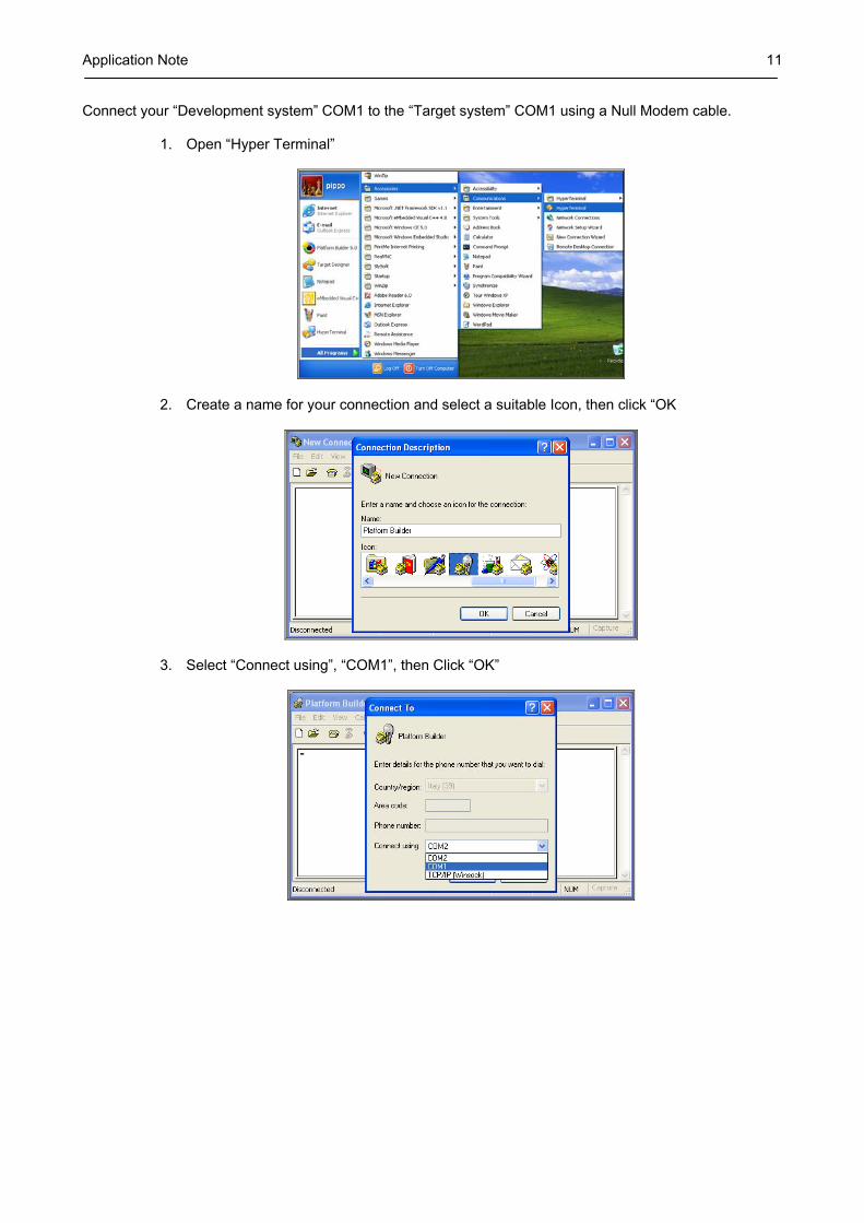
Connect your “Development system” COM1 to the “Target system” COM1 using a Null Modem cable.
1. Open “Hyper Terminal”
2. Create a name for your connection and select a suitable Icon, then click “OK
3. Select “Connect using”, “COM1”, then Click “OK”

Application Note 12
4. Set the following, then click “Apply”, “OK”
“Bits per second” 38400 “Data Bits” 8 “Parity” none “Stop Bits” 1 “Flow Control” none
5. The following shows the Hyper Terminal functioning whilst the “DTK-1X32-99” is booting.

Application Note 13
The two computers are connected together using the serial ports, for this you will require a null modem cable as described below: Unlisted pins have no connection, Extract from “The PC Handbook Seventh Edition”. Male 25-Pin D-Sub
System 1 Pin Pin System 2 TX 2 3 RX RX 3 2 TX
RTS 4 8 DCD CTS 5 DSR 6 20 DTR DCD 8 4 RTS
5 CTS DTR 20 6 DSR
Pins 3 and 4 are shorted together on each connector. Male 9-Pin D-Sub
System 1 Pin Pin System 2 TX 3 2 RX RX 2 3 TX
RTS 7 1 DCD CTS 8 DSR 6 4 DTR DCD 1 7 RTS
8 CTS DTR 4 6 DSR
Pins 7 and 8 are shorted together on each connector.
Application Note 14
Chapter 4 BIOS Settings
Some BIOS settings will need to be verified on the Target system to enable the Windows CE image to function correctly when downloading the image from the “Development system” and when using the Terminal Emulator. This chapter shows the required settings for using our own Nk.bin image; if you are using a locally generated image you may find that the BIOS setting would need to be different. If you require a copy of our example NK.BIN file as used for this document please contact Eurotech technical support at [email protected]
Application Note 15
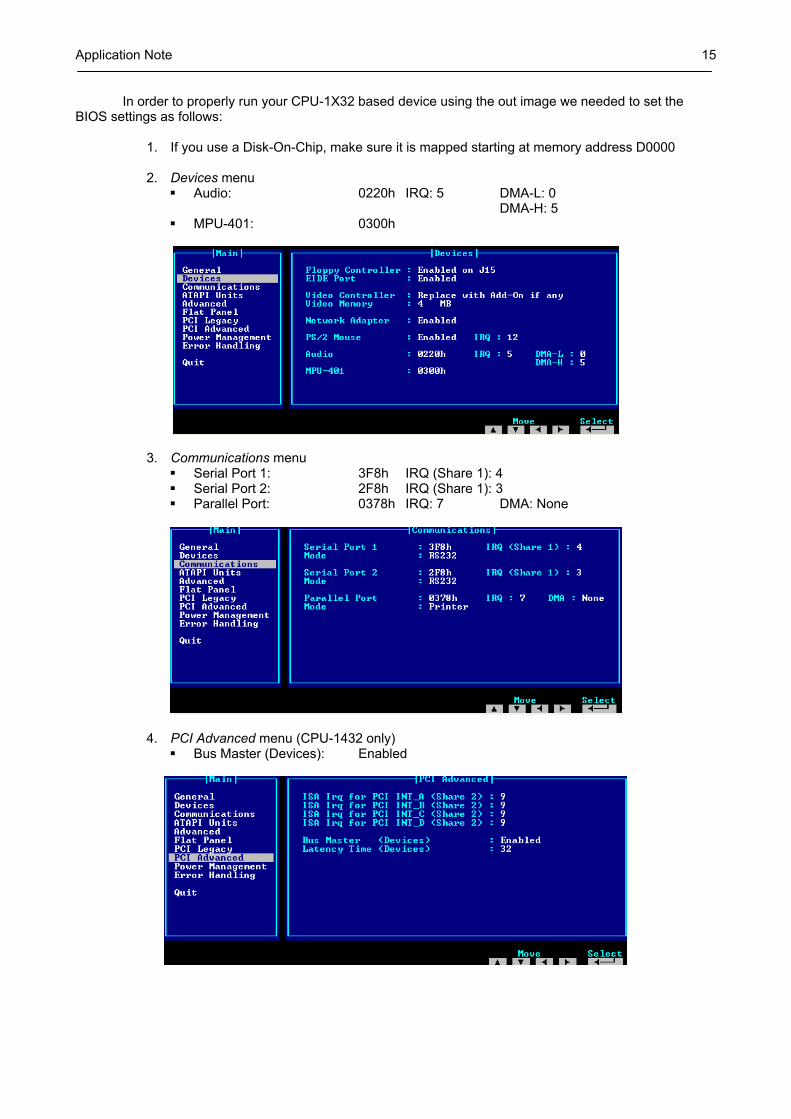
In order to properly run your CPU-1X32 based device using the out image we needed to set the BIOS settings as follows:
1. If you use a Disk-On-Chip, make sure it is mapped starting at memory address D0000 2. Devices menu
Audio: 0220h IRQ: 5 DMA-L: 0 DMA-H: 5 MPU-401: 0300h
3. Communications menu Serial Port 1: 3F8h IRQ (Share 1): 4 Serial Port 2: 2F8h IRQ (Share 1): 3 Parallel Port: 0378h IRQ: 7 DMA: None
4. PCI Advanced menu (CPU-1432 only) Bus Master (Devices): Enabled

Application Note 16
Chapter 5 Boot With Ethernet Procedure
Application Note 17
Initial Requirements: The instructions on the following pages were compiled using the following system and configuration:
CPU-1232 (Target System) ACS-9071-03 Ethernet Adaptor connected to J18
32MB Flash Card installed as primary boot device and boot information installed using
method one from chapter 1.
The Development system running Platform Builder 5.0 had an IP address of 10.0.0.1
The Autoexec.bat was edited to read: o Set NET_IRQ=0 o Set NET_IOBASE=0 o Set NET_IP=10.0.0.2
Null Modem cable was connected from Target system COM1 to the Development system
COM1 port. A crossed network cable was connecting the Target Ethernet adaptor to Development
system Ethernet port.
The Development system was OFF
NOTE: Our NK.BIN must have a Primary boot device connected to the IDE interface

Application Note 18
Set-up Procedure: 1. Launch “Platform Builder 5”
2. Open your project.
3. Set-up Target system parameters from within “Platform Builder 5”
Select menu, “Target”, “Connectivity options”

Application Note 19
Select Target device name (Add a new device name if required)
In the “Kernel Service Map” area
Set “Download:” dropdown menu to “Ethernet”
Click “Settings” button for the Download device.
Examine the window “Active Device” Boot the “Target Device” On the “Target Device”, Select one of the Ethernet Download Options when
the boot menu appears (Option 2,3 or 4) After a short time the system name should appear in the “Active Devices”
window, Select that device i.e. CEPC6858. The “IP Address:” and “Bootloader:” should change to reflect the Target
device (in our case: IP Address 10.0.0.2 and Bootloader 3.4) Click “OK”

Application Note 20
Set “Transport:” dropdown menu to “Ethernet”
Click “Settings” button for the Transport device
Confirm that the “Use device name from Bootloader” is checked
Select OK
In the section “Core Service Settings”
Select the radio button “Download Image”,” Always”
Click “Apply” then “Close”

Application Note 21
4. Connecting with the “Target Device”.
Select menu, “Target”, “Attach Device”
A Panel should displayed “Download Runtime Image to CE Device”
If the “Progress bar” shows no activity at this point, reboot the “Target
Device”, remember to select the correct Ethernet Download Options when the boot menu appears (Option 2,3 or 4)
After a short time the progress bar should start as below
After completion the Target system should boot to the Windows CE environment

Application Note 22
Chapter 6 Configuring a stand-alone system
This Chapter describes how to set-up your development system as a stand alone device:
You will require the following: 1. A working copy of an NK.BIN file. 2. All components connected to the Development system as required by the Windows CE set-
up, i.e. Hard Drive, CODEC etc It is best if you already have a NK.BIN that has been proven to work on your development system using the Ethernet download.

Application Note 23
1. Create a Bootloader disk as described in Chapter 1 2. Copy the NK.BIN file onto the Bootloader disk 3. Reboot the system (Remember to make sure that the boot sequence in the
NOTE: Remember to alter the boot sequence in the BIOS settings to reflect your device. 4. When the options menu appears Select option 1:
(CEPC_LOCAL, Boot CE/PC (local NK.BIN) 5. This should boot your NK.BIN file that is on the Boot Device
There are many ways to boot the Development system we have successfully tried the following methods:
• Using standard IDE Hard Drive o Use “SYS C:” to make the Hard Drive a system disk o A) Copy the contents of the Bootloader disk onto the hard drive or use one of the methods in
chapter 1. o Copy NK.BIN to the Hard drive o Remove any Floppy Disks as required and reboot the system. o You should get the boot menu appearing, Select option 1.
• From Disk-On-Chip o Install Disk-On-Chip (Check that pin 1 is correctly aligned) o Enable the Disk-On-Chip in the BIOS settings, and set base address as required. o Optional: Use “DUPDATE C: /S:DOC42.EXB /FIRST”, this makes the Disk-On-Chip the first
bootable device. o Use “SYS C:” to make the Disk-On-Chip a system disk o Copy the contents of the Bootloader disk onto the Disk-On-Chip. o Copy the NK.BIN file to the Disk-On-Chip. o Remove any Floppy Disks as required and reboot the system. o You should get the boot menu appearing, Select option 1.
• From a Flash-Disk
o Connect the Flash disc to the CPU-1X32 using an appropriate adaptor. • Example adaptors ADP-1020-00 or ADP-1020-01, for further information contact
[email protected] or [email protected]
o Use same method as standard IDE Hard Drive

Application Note 24
Chapter 7 Frequently asked questions
In our experience most problems have been related to one of the following:
The Windows CE image not functioning in the first place a. Try an image that is known to work
The image has dependencies that are not present i.e.
a. Hard Drive b. Sound CODEC
The Connectivity options are not correct
a. If you change the CPU, even though it may be the same model number the Download & Transport information may be incorrect
b. Check that the device appears correctly in the Connectivity options. Check Cable type and Connections
a. LAN must be a cross type b. RS232 must be a NULL modem type

Application Note 25
Where to find us Eurotech S.p.A. Via Jacopo Linussio, 1 - 33020 Amaro (UD) ITALY Tel. +39 0433 486258 - Fax +39 0433 486263 [email protected] http://www.eurotech.it ftp://ftp.eurotech.it

Application Note 26
Technical & Sales Assistance
If you have a technical question, please contact the Eurotech Customer Support Service
Old and new versions of manuals, application notes, patches, drivers and BIOS can be found at:
ftp://ftp.eurotech.it/
If you have a sales question, please contact your local Eurotech Sales Representative or the Regional Sales Office for your area.
Additional and latest information is available at Eurotech website, located at:
http://www.eurotech.it