CPSC 314 SHADERS, OPENGL, & JS RENDERING PIPELINEtmm/courses/314-16/slides/shaders-3x3.pdf ·...
11
2016-02-01 1 UGRAD.CS.UBC.CA/~CS314 Mikhail Bessmeltsev CPSC 314 SHADERS, OPENGL, & JS RENDERING PIPELINE WHAT IS RENDERING? Generating image from a 3D scene WHAT IS RENDERING? Generating image from a 3D scene Let’s think HOW. SCENE • A coordinate frame • 3D objects • Their materials • Lights • Cameras RENDERING RENDERING FRAME BUFFER • Portion of RAM on videocard (GPU) • What we see on the screen • Rendering destination SCREEN • Displays what’s in frame buffer • Terminology: Pixel: basic element on device Resolution: number of rows & columns in device Measured in • Absolute values (1K x 1K) • Density values (300 dots per inch) Scene CoordinateFrame 3D objects Materials Lights Cameras Framebuffer final image ?
Transcript of CPSC 314 SHADERS, OPENGL, & JS RENDERING PIPELINEtmm/courses/314-16/slides/shaders-3x3.pdf ·...

2016-02-01
1
UGRAD.CS.UBC.CA/~CS314
Mikhail Bessmeltsev
C P S C 314 S H A D E R S , O P E N G L , & J S
RENDERING PIPELINE WHAT IS RENDERING?
Generating image from a 3D scene
WHAT IS RENDERING?
Generating image from a 3D scene
Let’s think HOW.
SCENE
• A coordinate frame
• 3D objects
• Their materials
• Lights
• Cameras
RENDERING RENDERING
FRAME BUFFER
• Portion of RAM on videocard (GPU)
• What we see on the screen
• Rendering destination
SCREEN
• Displays what’s in frame buffer
• Terminology:
Pixel: basic element on deviceResolution: number of rows & columns in device
Measured in• Absolute values (1K x 1K)• Density values (300 dots per inch)
Scene
Coordinate Frame 3D objects Materials
Lights Cameras
Framebuffer
final image
?
2016-02-01
2
SINGLE OBJECT
• How to describe a single piece of geometry?
• So far geometry has been constructed for you.
• Triangle = 3 vertices
• Mesh = {vertices, triangles}
• Example
SHAPES: TRIANGLE MESHES SCENE
• How to describe a scene?
SCENE
• How to describe a scene?
• Local Transformations
Scene
Coordinate Frame 3D objects Materials
Lights Cameras
Framebuffer
final image
?
SKETCH OF A RENDERINGPIPELINE
• Scene• Coordinate frame
• 3D models• Coordinates
• Local transforms
• properties (color, material)
• Lights
• Camera
SKETCH OF A RENDERINGPIPELINE
• Scene• Coordinate frame
• 3D models• Coordinates
• properties (color, material)
• Lights
• Camera
• 2D positions of shapes• Depth of shapes• Normals
• Camera View • Image• Shape pixels
• Their color
• Which pixel is visible
OPENGL/WEBGL
• Open Graphics Library
• One of the most popular libraries for 2D/3D rendering
• Asoftware interface to communicate with graphics hardware
• Cross-language API
OPENGL RENDERING PIPELINE

2016-02-01
3
OPENGL RENDERING PIPELINE
Scene Camera Coords
Image
Device Coords
VERTEX SHADER VERTEX SHADER
• Vertices are stored in vertex buffer• Each one is processed by vertex shader
• Outputs 2D position• May compute per-vertex variables (normal, etc.)
O P E N G L R E N D E R I N G P I P E L I N E O P E N G L R E N D E R I N G P I P E L I N E
Javascript+ Three.JS
GLSL
GLSL (automatic) (automatic)
(automatic)
T H R E E . J S
• High-level library for Javascript
• Uses WebGL for rendering
• Has Scene, Mesh, Camera objects
• Scene is hierarchical
• Mesh has geometry and material properties
• Camera is used for rendering
G E O M E T R Y
• Triangle meshes• Set of vertices
• Triangle defines as {vertex_index1, vertex_index2, vertex_index3}
O P E N G L R E N D E R I N G P I P E L I N E
Javascript+ Three.JS
GLSL
GLSL (automatic) (automatic)
(automatic)
G L S L
• OpenGL shading language
• Used for Fragment and Vertex shaders
• Lots of useful stuff:• vec3, vec4, dvec4, mat4, sampler2D
• mat*vec, mat*mat
• Reflect, refract
• vec3 v( a.xy, 1)

2016-02-01
4
V E R T E X S H A D E R
• VS is run for each vertex SEPARATELY
• By default doesn’t know connectivity
• Input: vertex coordinates in Object Coordinate System
• Its main goal is to set gl_Position
Object coordinates -> WORLD coordinates -> VIEW coordinates
V E R T E X S H A D E R
• Except simple conversion to world coordinates
• You can do anything with vertices (or anything that’s passed)• e.g. deform vertices
• e.g. skinning!
[courtesy NVIDIA]
G E O M E T R Y( J AVA S C R I P T/ T H R E . J S )
var verticesOfCube = [
-1,-1,-1, 1,-1,-1,
-1,-1, 1, 1,-1, 1,
1, 1,-1,
1, 1, 1,
-1, 1,-1,
-1, 1, 1,
];
var indicesOfFaces = [
2,1,0, 0,3,2,
0,4,7, 7,3,0,
0,1,5, 5,4,0,
1,2,6, 6,5,1,
2,3,7, 7,6,2,
4,5,6, 6,7,4
];
var geometry = new THREE.PolyhedronGeometry(
verticesOfCube, indicesOfFaces, 6, 2 );
Image © Egon Rath
O P E N G L R E N D E R I N G P I P E L I N E
Javascript+ Three.JS
GLSL
GLSL (automatic) (automatic)
(automatic)
C A M E R A VI E W R A S T E R I Z A T I O N
•
R A S T E R I Z A T I O N

2016-02-01
5
•
R A S T E R I Z A T I O N R A S T E R I Z A T I O N - I N T E R P O L A T I O N R A S T E R I Z A T I O N - I N T E R P O L A T I O N
O P E N G L R E N D E R I N G P I P E L I N E
Javascript+ Three.JS
GLSL
GLSL (automatic) (automatic)
(automatic)
F R A G M E N T S H A D E R
• Fragment = data for drawing a pixel
• Has gl_FragCoord – 2D window coords
• May set color!
F R A G M E N T S H A D E R
• Common Tasks:• texture mapping
• per-pixel lighting and shading
• Synonymous with Pixel Shader
MINIMAL V E R T E X S H A D E Rvoid main()
{
// Transforming The Vertex
gl_Position = modelViewMatrix * position;
}
MINIMAL F R A G M E N T S H A D E Rvoid main()
{
// Setting Each Pixel To Red gl_FragColor =
vec4(1.0, 0.0, 0.0, 1.0);
}
MINIMAL V E R T E X S H A D E Rvoid main()
{
// Transforming The Vertex
gl_Position = modelViewMatrix * position;
}
MINIMAL F R A G M E N T S H A D E Rvoid main()
{
// Setting Each Pixel To Red
gl_FragColor = vec4(1.0, 0.0, 0.0, 1.0);
}
defined by Three.JS
MINIMAL V E R T E X S H A D E Rvoid main()
{
// Transforming The Vertex
gl_Position = modelViewMatrix * position;
}
MINIMAL F R A G M E N T S H A D E Rvoid main()
{
// Setting Each Pixel To Red
gl_FragColor = vec4(1.0, 0.0, 0.0, 1.0);
}
defined by Three.JS
𝑥𝑦𝑧1.0

2016-02-01
6
MINIMAL V E R T E X S H A D E Rvoid main()
{
// Transforming The Vertex
gl_Position = modelViewMatrix * position;
}
MINIMAL F R A G M E N T S H A D E Rvoid main()
{
// Setting Each Pixel To Red
gl_FragColor = vec4(1.0, 0.0, 0.0, 1.0);
}
defined by Three.JS
𝑥𝑦𝑧1.0
view coordinate system
MINIMAL V E R T E X S H A D E Rvoid main()
{
// Transforming The Vertex
gl_Position = modelViewMatrix * position;
}
}
MINIMAL F R A G M E N T S H A D E Rvoid main()
{
// Setting Each Pixel To Red
gl_FragColor = vec4(1.0, 0.0, 0.0, 1.0);
defined by Three.JS
𝑥𝑦𝑧1.0
view coordinate system
Red Green Blue Alpha
V E R T E X S H A D E R – E X A M P L E 2uniform float uVertexScale; attribute
vec3 vColor; varying vec3 fColor;
* uVertexScale, position.y, 0.0,1.0);
void main() {
gl_Position = vec4(position.x
fColor = vColor;
}
C O N C E P T S
• uniform• same for all vertices
• varying• computed per vertex, automatically interpolated for fragments
• attribute• some values per vertex
• available only in Vertex Shader
C O N C E P T S
• uniform• same for all vertices
• varying• computed per vertex, automatically interpolated for fragments
• attribute• some values per vertex
• available only in Vertex Shader
JS + Three.JS Vertex Shader FragmentShader
JS + Three.JS VertexShader
Vertex Shader Fragment Shader
V E R T E X S H A D E R
F R A G M E N T S H A D E R A T T A C H I N G S H A D E R S
= new THREE.ShaderMaterial({
remotePosition,
var remoteMaterial
uniforms: {
remotePosition:
},});
//here goes loading shader files into shaders[] …
remoteMaterial.vertexShader =
remoteMaterial.fragmentShader
shaders['glsl/remote.vs.glsl'];
= shaders['glsl/remote.fs'];
THREE.SphereGeometry(1, 32, 32);var remoteGeometry = new
var remote = new THREE.Mesh(remoteGeometry, remoteMaterial);
scene.add(remote);
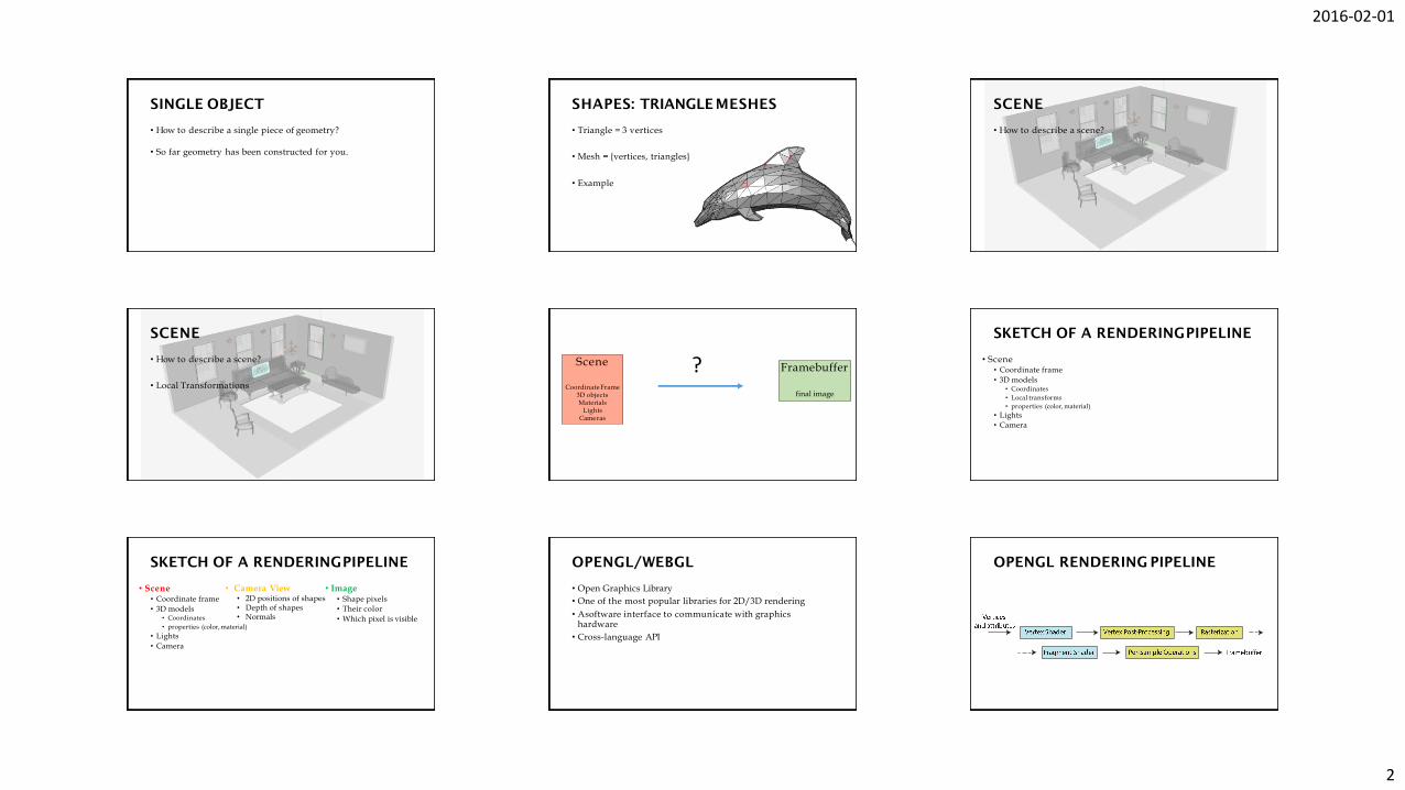
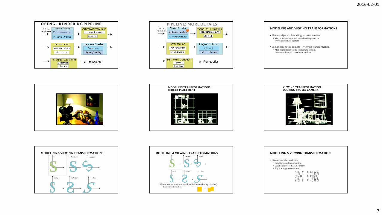
PIPELINE: MORE DETAILS
2016-02-01
7
O P E N G L R E N D E R I N G P I P E L I N E PIPELINE: MORE DETAILS
• Placing objects - Modeling transformations• Map points from object coordinate system to
world coordinate system
• Looking from the camera - Viewing transformation• Map points from world coordinate system
to camera (or eye) coordinate system
MODELING AND VIEWING TRANSFORMATIONS
MODELING TRANSFORMATIONS:
OBJECT PLACEMENT
VIEWING TRANSFORMATION:
LOOKING FROMA CAMERA
MODELING & VIEWING TRANSFORMATIONS
• Other transformations (not handled by rendering pipeline):• Freeform deformation
MODELING & VIEWING TRANSFORMATIONS
• Linear transformations• Rotations, scaling, shearing
• Can be expressed as 3x3 matrix
• E.g. scaling (non uniform):
MODELING & VIEWING TRANSFORMATION
0
0y
1 z
0 x
z'y' 0
x' 2 0
3
0

2016-02-01
8
• Affine transformations• Linear transformations + translations
• Can be expressed as 3x3 matrix + 3 vector
• E.g. scale+ translation:
• Another representation: 4x4 homogeneous matrix
MODELING & VIEWING TRANSFORMATION
z
tx
1 z t 0
0y t y
0 x
z'y' 0
x' 2 0
3
0
MATRICES
• Object coordinates -> World coordinates• Model Matrix
• One per object
• World coordinates -> Camera coordinates• View Matrix
• One per camera
PIPELINE: MORE DETAILS
• Purpose:• Project 3D geometry to 2D image plane
• Simulates a camera
• Camera model:• Pinhole camera (single view point)
• More complex camera models exist, but are less common in CG
PERSPECTIVE TRANSFORMATION PERSPECTIVE PROJECTION
• In computer graphics:• Image plane conceptually in front of center of projection
• Perspective transformation is one of projective transformations
• Linear & affine transformations also belong to this class
• All projective transformations can be expressed as 4x4 matrix operations
PERSPECTIVE TRANSFORMATION
PIPELINE: MORE DETAILS
CLIPPING
• Removing invisible geometry• Geometry outside viewing frustum
• Plus too far or too near one
• Optimization
PIPELINE: MORE DETAILS

2016-02-01
9
SCAN CONVERSION/RASTERIZATION
• Convert continuous 2D geometry to discrete
• Raster display – discrete grid of elements
• Terminology
• Screen Space: Discrete 2D Cartesian coordinate system of the screen pixels
SCAN CONVERSION SCAN CONVERSION
• Problem:• Line is infinitely thin, but image has finite resolution
• Results in steps rather than a smooth line• Jaggies
• Aliasing
• One of the fundamental problems in computer graphics
SCAN CONVERSION
•
SCAN CONVERSION
Linearly interpolate per-pixel color from vertex color values Treat every channel of RGB color separately
COLOR INTERPOLATION
s
t
color
• Example:
COLOR INTERPOLATION
s
t
red
s
t
green
s
t
blue
PIPELINE: MORE DETAILS
TEXTURING
(s1,t1)
(s2,t2)
t
(s0,t0)
s
2016-02-01
10
TEXTURING
(s1,t1)
(s2,t2)
t
(s0,t0)
s
TEXTURE MAPPING DISPLACEMENT MAPPING
• Issues:• Computing 3D/2D map (low distortion)
• How to map pixel from texture (texels) to screen pixels• Texture can appear widely distorted inrendering
• Magnification / minification of textures
• Filtering of textures
• Preventing aliasing (anti-aliasing)
TEXTURING
PIPELINE: MORE DETAILS
LIGHTING
COMPLEX LIGHTING AND SHADINGPIPELINE: MORE DETAILS
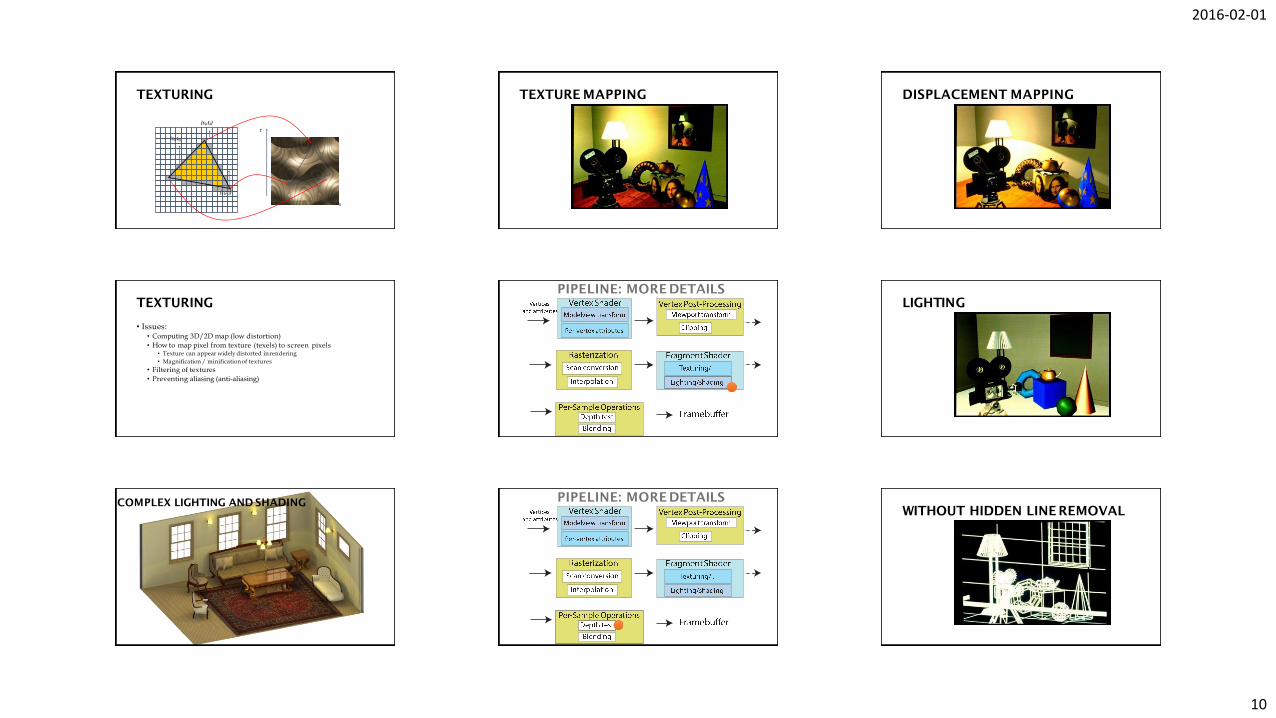
WITHOUT HIDDEN LINE REMOVAL
2016-02-01
11
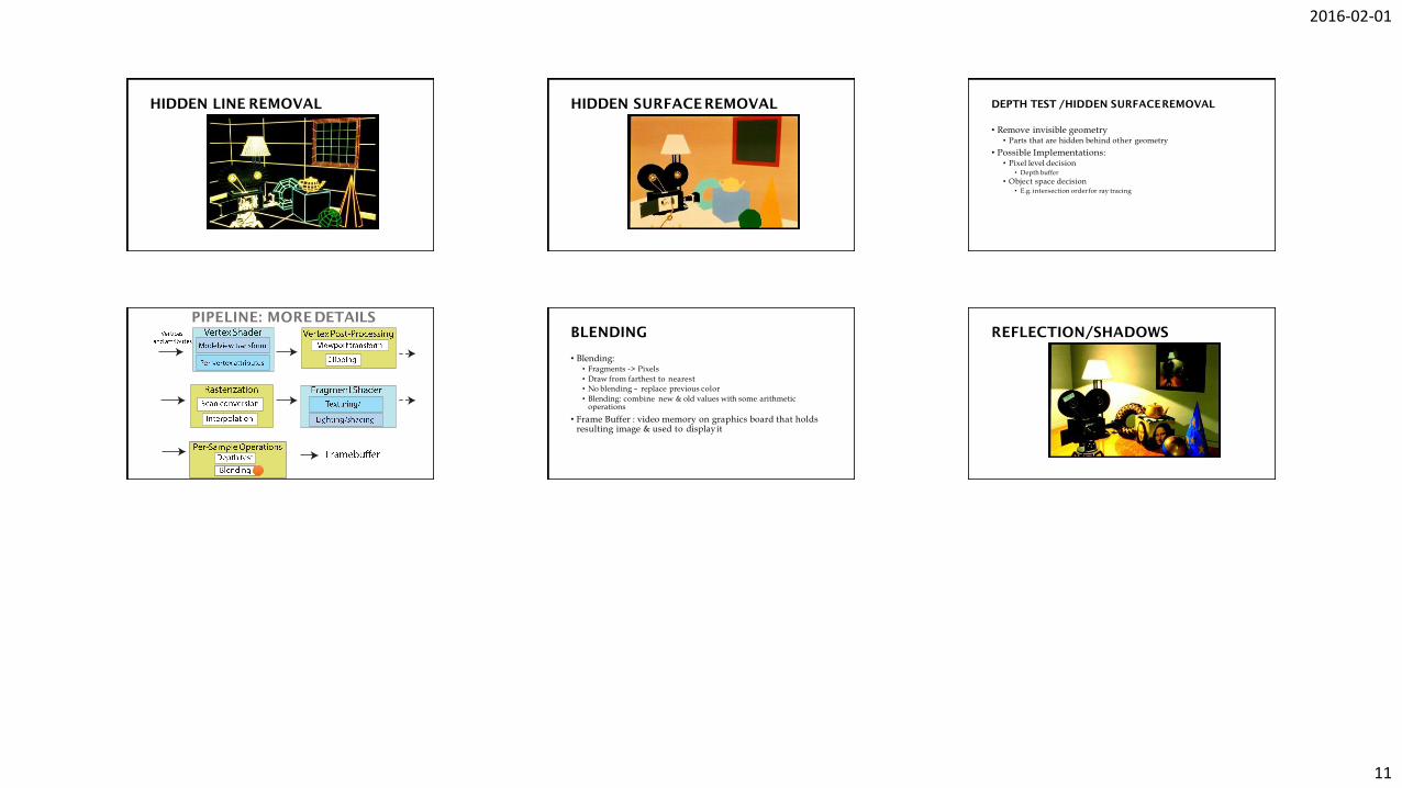
HIDDEN LINE REMOVAL HIDDEN SURFACE REMOVAL
• Remove invisible geometry• Parts that are hidden behind other geometry
• Possible Implementations:• Pixel level decision
• Depth buffer
• Object space decision• E.g. intersection order for ray tracing
DEPTH TEST /HIDDEN SURFACEREMOVAL
PIPELINE: MORE DETAILS
• Blending:• Fragments -> Pixels
• Draw from farthest to nearest
• No blending – replace previous color
• Blending: combine new & old values with some arithmetic operations
• Frame Buffer : video memory on graphics board that holds resulting image & used to displayit
BLENDING REFLECTION/SHADOWS