CPRE 583 Reconfigurable Computing Lecture 2: 8/26/2011 (VHDL Overview 1 )
Upload
hakeem-ingramCategory
view
32download
0description
CprE / ComS 583Reconfigurable Computing
Prof. Joseph ZambrenoDepartment of Electrical and Computer EngineeringIowa State University
Lecture #21 – HW/SW Codesign

CprE 583 – Reconfigurable ComputingNovember 2, 2006 Lect-21.2
Quick Points
• Midterm graded and returned• Average – 84.5• Median – 85.0• Maximum – 95.0• Minimum – 72.0• Standard Deviation – 6.65
CprE 583 – Reconfigurable ComputingNovember 2, 2006 Lect-21.3
HW #4 Discussion
• Problem 1 – did just a simple adder work?• Problem 2 – how did you implement the
permutation table?• Problem 3 – did you use a counter?
CprE 583 – Reconfigurable ComputingNovember 2, 2006 Lect-21.4
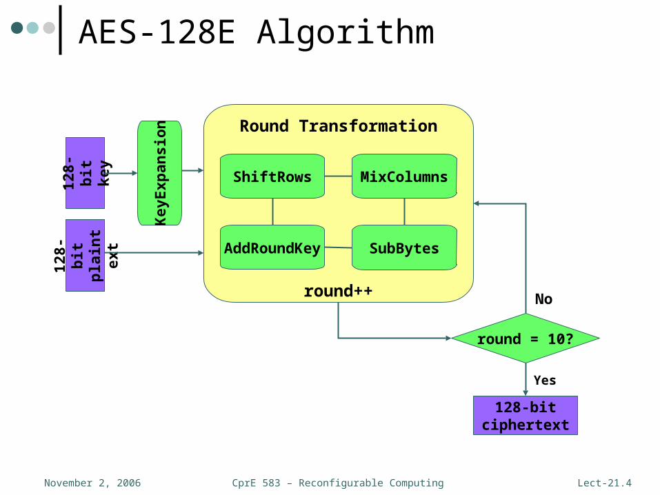
AES-128E Algorithm12
8-b
itp
lain
text
128-
bit
key
Round Transformation
round++
round = 10?
SubBytes
ShiftRows
AddRoundKey
128-bitciphertext
Yes
No
Key
Exp
ansi
onMixColumns

CprE 583 – Reconfigurable ComputingNovember 2, 2006 Lect-21.5
S-box
0 1 2 3 4 5 6 7 8 9 a b c d e f0123456789abcdef
63 7c 77 7b f2 6b 6f c5 30 01 67 2b fe d7 ab 76ca 82 c9 7d fa 09 21 25 c5 c3 ee 1e a6 4f 8c 20b7 fd 93 26 36 fa 25 3a 46 b5 aa 0c a6 3a 77 5d04 c7 23 c3 18 42 dd dc b5 95 8c 57 69 84 00 dc09 83 2c 1a 1b c7 20 8c fa e1 cb 6d 0d fa 43 7353 d1 00 ed 20 43 41 99 6d 0d 44 5a 8e 2a 60 4ad0 ef aa fb 43 1b 12 4a e1 f2 ff 4a bc fd 0f a651 a3 40 8f 92 cc 3a a6 fc 09 c7 ef 00 25 89 aacd 0c 13 ec 5f 4a 35 af 4f 12 dc ed 51 3b 1b dc60 81 4f dc 2a 4a 46 81 55 43 88 bc 67 13 15 bae0 32 3a 0a 06 6f 25 60 23 00 c3 60 60 48 b5 49e7 c8 37 6d d5 12 ed 45 43 a6 25 4f 19 e1 ed 4fba 25 25 2e a6 2c 34 a6 97 ee 36 33 33 1f 6f 5170 b5 b5 66 40 3f 1b bb b5 63 1b b5 6f 25 ba 4ae1 98 11 11 56 af b5 b5 20 aa b5 2a 4a 00 60 228c 89 0d 0d 82 00 ba 8c 4f 43 17 0d 04 b5 09 09
y
x
Overview of AES (cont.)
• 128-bit input is copied into a two-dimensional (4x4) byte array referred to as the state• Round transformations operate on the state array• Final state copied back into 128-bit output
• AES makes use of a non-linear substitution function that operates on a single byte• Can be simplified as a look-up table (S-box)
CprE 583 – Reconfigurable ComputingNovember 2, 2006 Lect-21.6
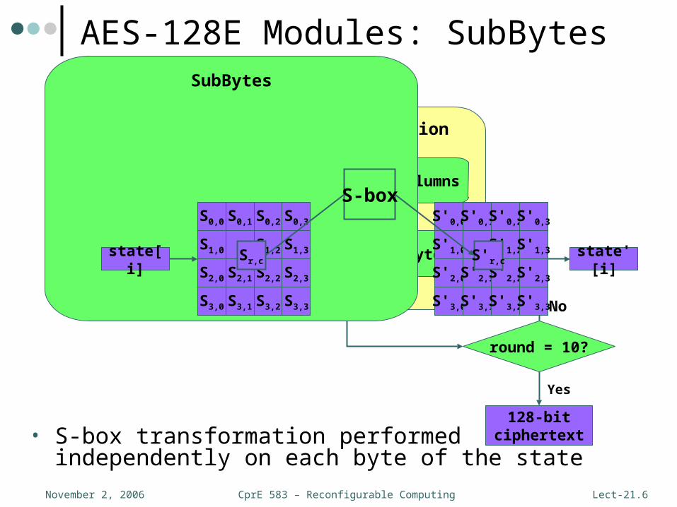
AES-128E Modules: SubBytes
Key
Exp
ansi
on
128-
bit
pla
inte
xt12
8-b
itk
ey
Round Transformation
round++
round = 10?
SubBytes
ShiftRows
AddRoundKey
128-bitciphertext
Yes
No
MixColumns
SubBytes
• S-box transformation performed independently on each byte of the state
S-boxS0,0 S0,1 S0,2 S0,3
S1,0 S1,2 S1,3
S2,0 S2,1 S2,2 S2,3
S3,0 S3,1 S3,2 S3,3
Sr,c
S'0,0 S'0,1 S'0,2 S'0,3
S'1,0 S'1,2 S'1,3
S'2,0 S'2,1 S'2,2 S'2,3
S'3,0 S'3,1 S'3,2 S'3,3
S'r,cstate[i] state'[i]
CprE 583 – Reconfigurable ComputingNovember 2, 2006 Lect-21.7
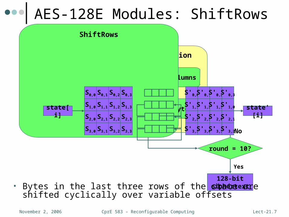
AES-128E Modules: ShiftRows
Key
Exp
ansi
on
128-
bit
pla
inte
xt12
8-b
itk
ey
Round Transformation
round++
round = 10?
SubBytes
ShiftRows
AddRoundKey
128-bitciphertext
Yes
No
MixColumns
ShiftRows
• Bytes in the last three rows of the state are shifted cyclically over variable offsets
S0,0 S0,1 S0,2 S0,3
S1,0 S1,1 S1,2 S1,3
S2,0 S2,1 S2,2 S2,3
S3,0 S3,1 S3,2 S3,3
S'0,0 S'0,1 S'0,2 S'0,3
S'1,1 S'1,2 S'1,3 S'1,0
S'2,2 S'2,3 S'2,0 S'2,1
S'3,3 S'3,0 S'3,1 S'3,2
state[i] state'[i]
CprE 583 – Reconfigurable ComputingNovember 2, 2006 Lect-21.8
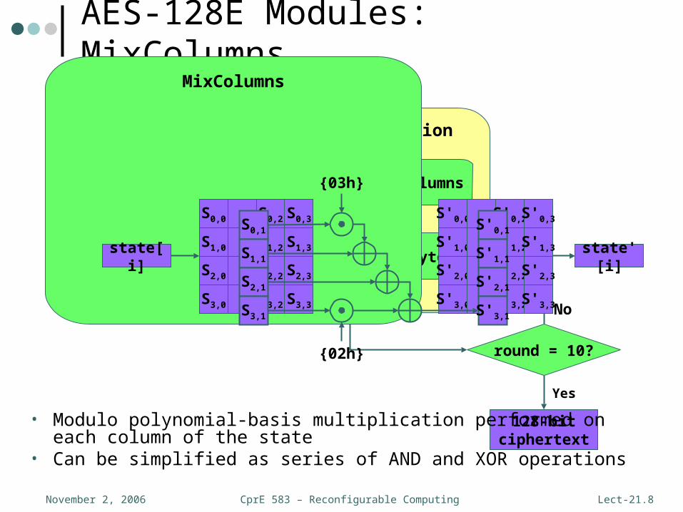
AES-128E Modules: MixColumns
Key
Exp
ansi
on
128-
bit
pla
inte
xt12
8-b
itk
ey
Round Transformation
round++
round = 10?
SubBytes
ShiftRows
AddRoundKey
128-bitciphertext
Yes
No
MixColumns
MixColumns
• Modulo polynomial-basis multiplication performed on each column of the state
• Can be simplified as series of AND and XOR operations
state[i] state'[i]
{03h}
{02h}
S0,0 S0,2 S0,3
S1,0 S1,2 S1,3
S2,0 S2,2 S2,3
S3,0 S3,2 S3,3
S0,1
S1,1
S2,1
S3,1
S'0,0 S'0,2 S'0,3
S'1,0 S'1,2 S'1,3
S'2,0 S'2,2 S'2,3
S'3,0 S'3,2 S'3,3
S'0,1
S'1,1
S'2,1
S'3,1
CprE 583 – Reconfigurable ComputingNovember 2, 2006 Lect-21.9
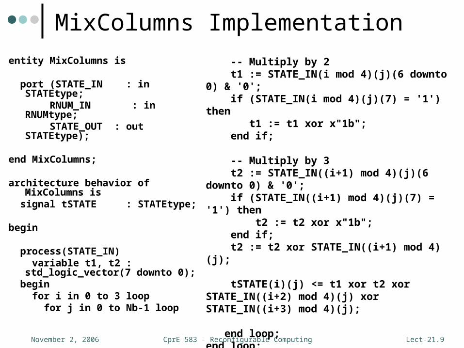
MixColumns Implementation
entity MixColumns is
port (STATE_IN : in STATEtype; RNUM_IN : in RNUMtype; STATE_OUT : out STATEtype);
end MixColumns;
architecture behavior of MixColumns is signal tSTATE : STATEtype;
begin
process(STATE_IN) variable t1, t2 : std_logic_vector(7
downto 0); begin for i in 0 to 3 loop for j in 0 to Nb-1 loop
-- Multiply by 2 t1 := STATE_IN(i mod 4)(j)(6 downto 0) & '0'; if (STATE_IN(i mod 4)(j)(7) = '1') then t1 := t1 xor x"1b"; end if;
-- Multiply by 3 t2 := STATE_IN((i+1) mod 4)(j)(6 downto 0) & '0'; if (STATE_IN((i+1) mod 4)(j)(7) = '1') then t2 := t2 xor x"1b"; end if; t2 := t2 xor STATE_IN((i+1) mod 4)(j);
tSTATE(i)(j) <= t1 xor t2 xor STATE_IN((i+2) mod 4)(j) xor STATE_IN((i+3) mod 4)(j); end loop;end loop;
end process;

CprE 583 – Reconfigurable ComputingNovember 2, 2006 Lect-21.10
AES-128E Modules: AddRoundKey
Key
Exp
ansi
on
128-
bit
pla
inte
xt12
8-b
itk
ey
Round Transformation
round++
round = 10?
SubBytes
ShiftRows
AddRoundKey
128-bitciphertext
Yes
No
MixColumns
AddRoundKey
• Words from the round-specific key are XORed into columns of the state
S0,0 S0,2 S0,3
S1,0 S1,2 S1,3
S2,0 S2,2 S2,3
S3,0 S3,2 S3,3
S'0,0 S'0,2 S'0,3
S'1,0 S'1,2 S'1,3
S'2,0 S'2,2 S'2,3
S'3,0 S'3,2 S'3,3
S0,1
S1,1
S2,1
S3,1
S'0,1
S'1,1
S'2,1
S'3,1
Rkey[i]
w[0] w[2] w[3]w[1]
state[i] state'[i]

CprE 583 – Reconfigurable ComputingNovember 2, 2006 Lect-21.11
AddRoundKey Implementation
entity AddRoundKey is port(STATE_IN : in STATEtype; KEY_IN : in KEYtype; STATE_OUT : out STATEtype);end AddRoundKey;
architecture behavior of AddRoundKey isbegin
process(STATE_IN, KEY_IN) begin
for j in 0 to (Nb-1) loop STATE_OUT(0)(j) <= STATE_IN(0)(j) xor KEY_IN(j)(31 downto 24); STATE_OUT(1)(j) <= STATE_IN(1)(j) xor KEY_IN(j)(23 downto 16); STATE_OUT(2)(j) <= STATE_IN(2)(j) xor KEY_IN(j)(15 downto 8); STATE_OUT(3)(j) <= STATE_IN(3)(j) xor KEY_IN(j)(7 downto 0); end loop;
end process;
end behavior;
CprE 583 – Reconfigurable ComputingNovember 2, 2006 Lect-21.12
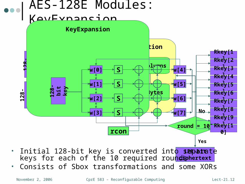
AES-128E Modules: KeyExpansion
Key
Exp
ansi
on
128-
bit
pla
inte
xt12
8-b
itk
ey
Round Transformation
round++
round = 10?
SubBytes
ShiftRows
AddRoundKey
128-bitciphertext
Yes
No
MixColumns
KeyExpansion
• Initial 128-bit key is converted into separate keys for each of the 10 required rounds
• Consists of Sbox transformations and some XORs
128-
bit
key
Rkey[1]
Rkey[2]
Rkey[3]
Rkey[4]
Rkey[5]
Rkey[6]
Rkey[7]
Rkey[8]
Rkey[9]
Rkey[10]
S
S
S
S
rcon
w[0]
w[1]
w[2]
w[3]
w[4]
w[5]
w[6]
w[7]
CprE 583 – Reconfigurable ComputingNovember 2, 2006 Lect-21.13
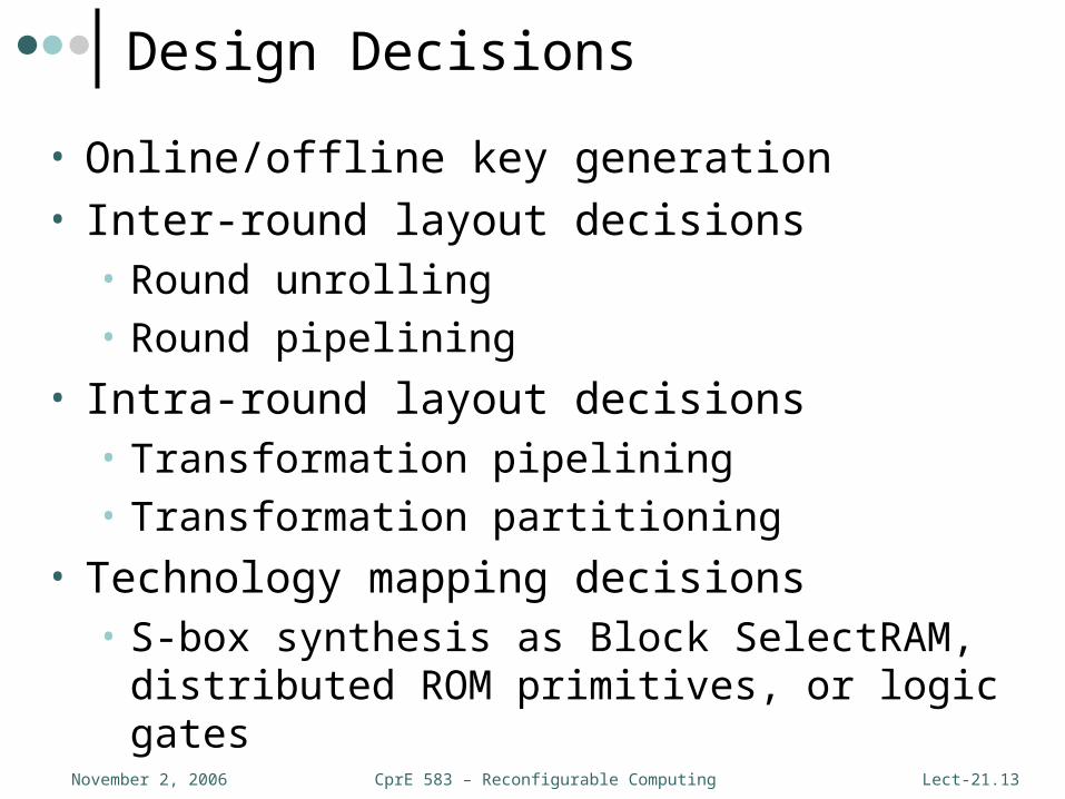
Design Decisions
• Online/offline key generation• Inter-round layout decisions
• Round unrolling• Round pipelining
• Intra-round layout decisions• Transformation pipelining• Transformation partitioning
• Technology mapping decisions• S-box synthesis as Block SelectRAM,
distributed ROM primitives, or logic gates

CprE 583 – Reconfigurable ComputingNovember 2, 2006 Lect-21.14
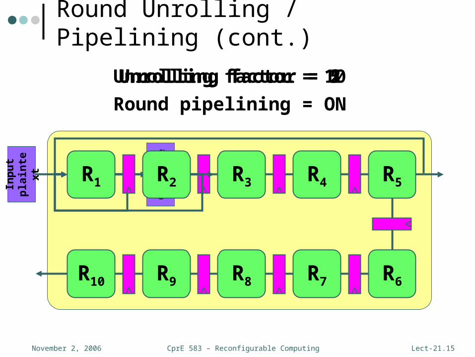
Round Unrolling / Pipelining
• Unrolling replaces a loop body (round) with N copies of that loop body
• AES-128E algorithm is a loop that iterates 10 times – N є [1, 10]• N = 1 corresponds to original looping case• N = 10 is a fully unrolled implementation
• Pipelining is a technique that increases the number of blocks of data that can be processed concurrently• Pipelining in hardware can be implemented by
inserting registers• Unrolled rounds can be split into a certain number of
pipeline stages• These transformations will increase throughput but
increase area and latency
CprE 583 – Reconfigurable ComputingNovember 2, 2006 Lect-21.15
Unrolling factor = 10Unrolling factor = 2Unrolling factor = 1Unrolling factor = 5
Round Unrolling / Pipelining (cont.)In
pu
tp
lain
text
R1 Ou
tpu
tC
iph
erte
xtR2 R3 R4 R5
R6R7R8R9R10
Round pipelining = ON
CprE 583 – Reconfigurable ComputingNovember 2, 2006 Lect-21.16
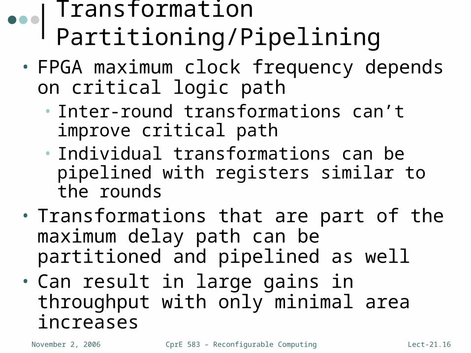
Transformation Partitioning/Pipelining
• FPGA maximum clock frequency depends on critical logic path• Inter-round transformations can’t improve
critical path• Individual transformations can be pipelined with
registers similar to the rounds• Transformations that are part of the maximum
delay path can be partitioned and pipelined as well
• Can result in large gains in throughput with only minimal area increases
CprE 583 – Reconfigurable ComputingNovember 2, 2006 Lect-21.17
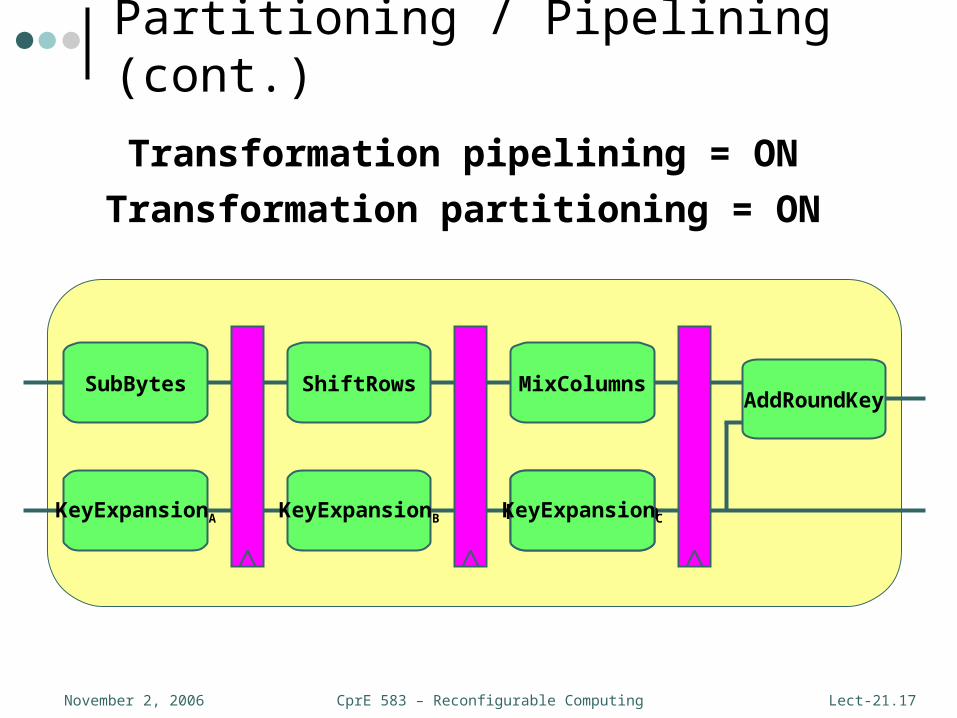
Transformation pipelining = ON
Partitioning / Pipelining (cont.)
Transformation partitioning = ON
SubBytes ShiftRows MixColumns
KeyExpansion
AddRoundKey
KeyExpansionB KeyExpansionCKeyExpansionA

CprE 583 – Reconfigurable ComputingNovember 2, 2006 Lect-21.18
S-box Technology Mapping
• With synthesis primitives, can map the S-box lookup tables to different hardware components
• Two S-boxes can fit on a single Block SelectRAM
constant SSYNROMSTYLE: string := “select_rom”; -- {logic, select_rom}entity Sbox is
port(BYTE_IN : in std_logic_vector(7 downto 0); BYTE_OUT : out std_logic_vector(7 downto 0));
attribute syn_romstyle : string; attribute syn_romstyle of BYTE_OUT : signal is SSYNROMSTYLE;
end Sbox;...
Sample VHDL code

CprE 583 – Reconfigurable ComputingNovember 2, 2006 Lect-21.19
Recap – Retiming

CprE 583 – Reconfigurable ComputingNovember 2, 2006 Lect-21.20
weight(e) = weight(e) + lag(head(e)) - lag(tail(e))
Recap – Retiming (cont.)
CprE 583 – Reconfigurable ComputingNovember 2, 2006 Lect-21.21
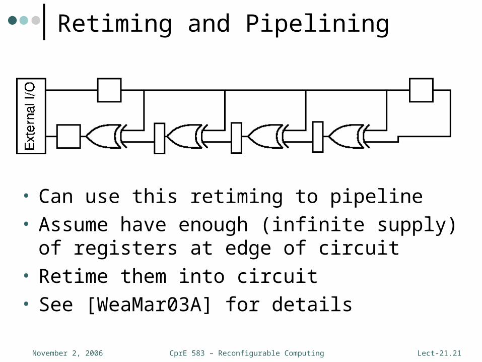
Retiming and Pipelining
• Can use this retiming to pipeline• Assume have enough (infinite supply) of
registers at edge of circuit• Retime them into circuit• See [WeaMar03A] for details

CprE 583 – Reconfigurable ComputingNovember 2, 2006 Lect-21.22
Recap – Retiming and Covering
CprE 583 – Reconfigurable ComputingNovember 2, 2006 Lect-21.23
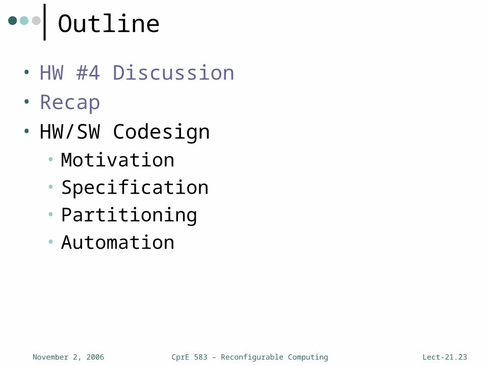
Outline
• HW #4 Discussion• Recap• HW/SW Codesign
• Motivation• Specification• Partitioning• Automation

CprE 583 – Reconfigurable ComputingNovember 2, 2006 Lect-21.24
Hardware/Software Codesign
• Definition 1 – the concurrent and co-operative design of hardware and software components of an embedded system
• Definition 2 – A design methodology supporting the cooperative and concurrent development of hardware and software (co-specification, co-development, and co-verification) in order to achieve shared functionality and performance goals for a combined system [MicGup97A]
CprE 583 – Reconfigurable ComputingNovember 2, 2006 Lect-21.25
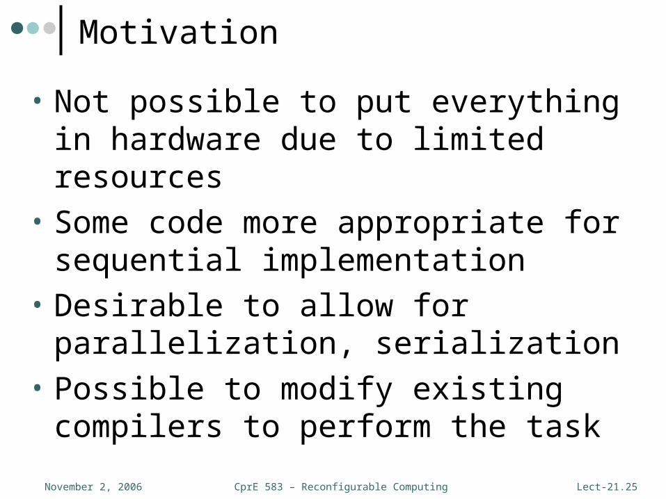
Motivation
• Not possible to put everything in hardware due to limited resources
• Some code more appropriate for sequential implementation
• Desirable to allow for parallelization, serialization
• Possible to modify existing compilers to perform the task
CprE 583 – Reconfigurable ComputingNovember 2, 2006 Lect-21.26
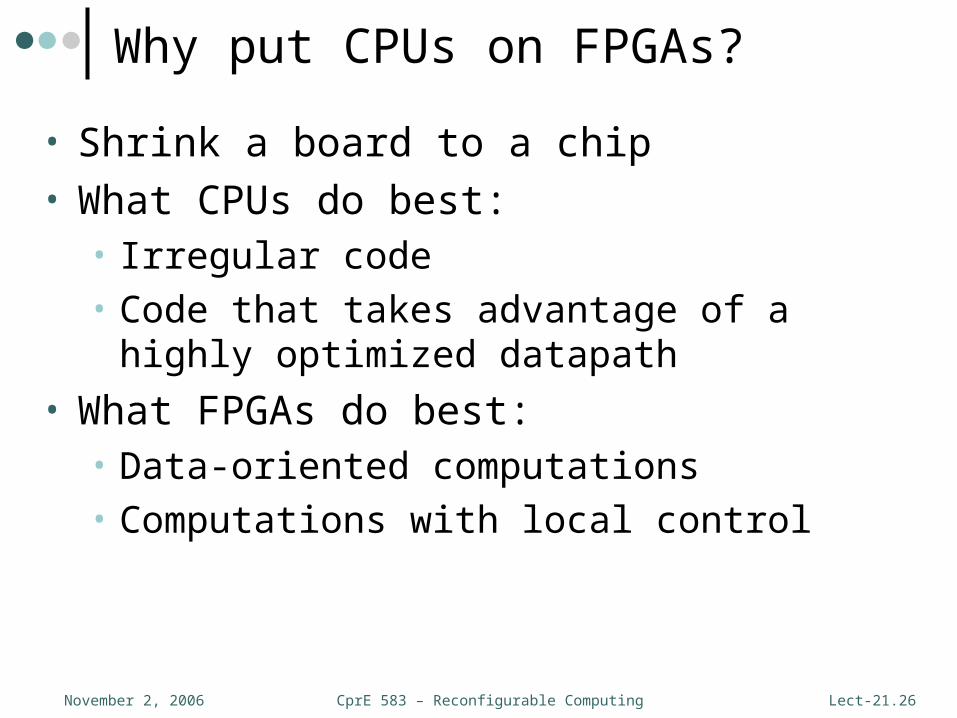
Why put CPUs on FPGAs?
• Shrink a board to a chip• What CPUs do best:
• Irregular code• Code that takes advantage of a highly optimized
datapath
• What FPGAs do best:• Data-oriented computations• Computations with local control

CprE 583 – Reconfigurable ComputingNovember 2, 2006 Lect-21.27
• Most recent work addressing this problem assumes relatively slow bus interface
• FPGA has direct interface to memory in this model
General-PurposeProcessor
Memory
FPGA
Memory bus
Computational Model

CprE 583 – Reconfigurable ComputingNovember 2, 2006 Lect-21.28
Hardware/Software Partitioning
CPUHW
Accelerator
if (foo < 8) {for (i=0; i<N; i++)
x[i] = y[i]*z[i];}
CprE 583 – Reconfigurable ComputingNovember 2, 2006 Lect-21.29
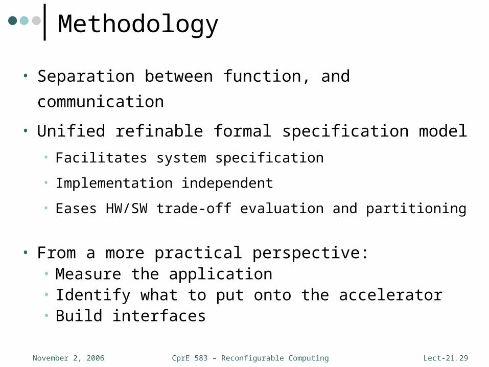
Methodology
• Separation between function, and communication
• Unified refinable formal specification model
• Facilitates system specification
• Implementation independent
• Eases HW/SW trade-off evaluation and partitioning
• From a more practical perspective:• Measure the application• Identify what to put onto the accelerator• Build interfaces
CprE 583 – Reconfigurable ComputingNovember 2, 2006 Lect-21.30
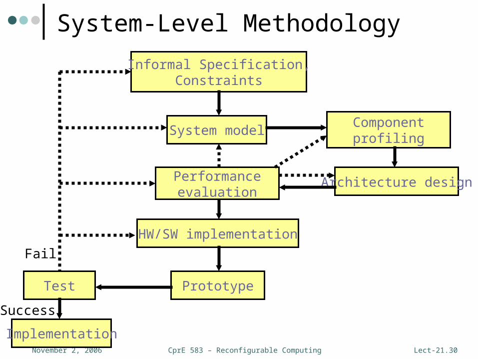
Informal Specification,Constraints
System model
Architecture design
HW/SW implementation
PrototypeTest
Implementation
Fail
Success
Componentprofiling
Performanceevaluation
System-Level Methodology

CprE 583 – Reconfigurable ComputingNovember 2, 2006 Lect-21.31
Concurrency
• Concurrent applications provide the most speedup
CPU accelerator
if (a > b) ... x[i] = y[i] * z[i]
No data dependencies
CprE 583 – Reconfigurable ComputingNovember 2, 2006 Lect-21.32
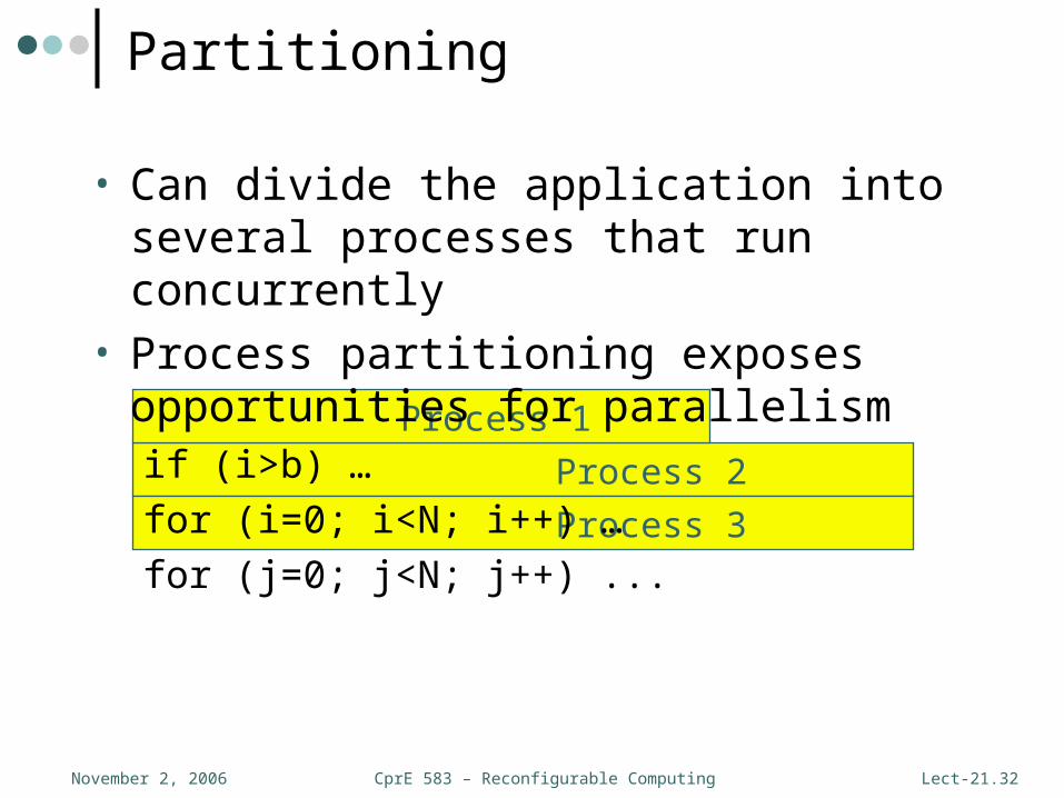
Process 2
Process 3
Process 1
Partitioning
• Can divide the application into several processes that run concurrently
• Process partitioning exposes opportunities for parallelismif (i>b) …
for (i=0; i<N; i++) …
for (j=0; j<N; j++) ...

CprE 583 – Reconfigurable ComputingNovember 2, 2006 Lect-21.33
process (a, b, c) in port a, b; out port c;{ read(a); … write(c);}
Specification
Line (){ a = … … detach}
Processor
Capture
Model FPGA
Partition
Synthesize
Interface
Automating System Partitioning
• Good partitioning mechanism:1)Minimize communication across bus
2)Allows parallelism both hardware (FPGA) and processor operating concurrently
3)Near peak processor utilization at all times (performing useful work)
CprE 583 – Reconfigurable ComputingNovember 2, 2006 Lect-21.34
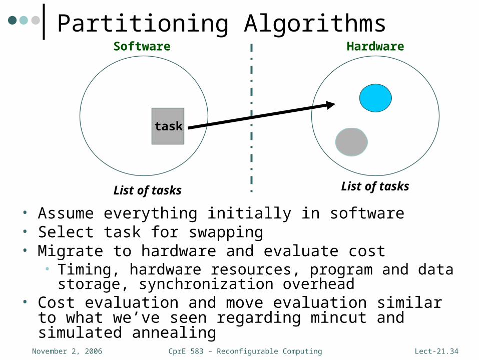
task
Software Hardware
List of tasks List of tasks
Partitioning Algorithms
• Assume everything initially in software• Select task for swapping• Migrate to hardware and evaluate cost
• Timing, hardware resources, program and data storage, synchronization overhead
• Cost evaluation and move evaluation similar to what we’ve seen regarding mincut and simulated annealing

CprE 583 – Reconfigurable ComputingNovember 2, 2006 Lect-21.35
Multi-threaded Systems
• Single thread:
• Multi-thread:

CprE 583 – Reconfigurable ComputingNovember 2, 2006 Lect-21.36
Performance Analysis
• Single threaded:• Find longest possible
execution path
• Multi-threaded with no synchronization:• Find the longest of
several execution paths
• Multi-threaded with synchronization:• Find the worst-case
synchronization conditions
CprE 583 – Reconfigurable ComputingNovember 2, 2006 Lect-21.37
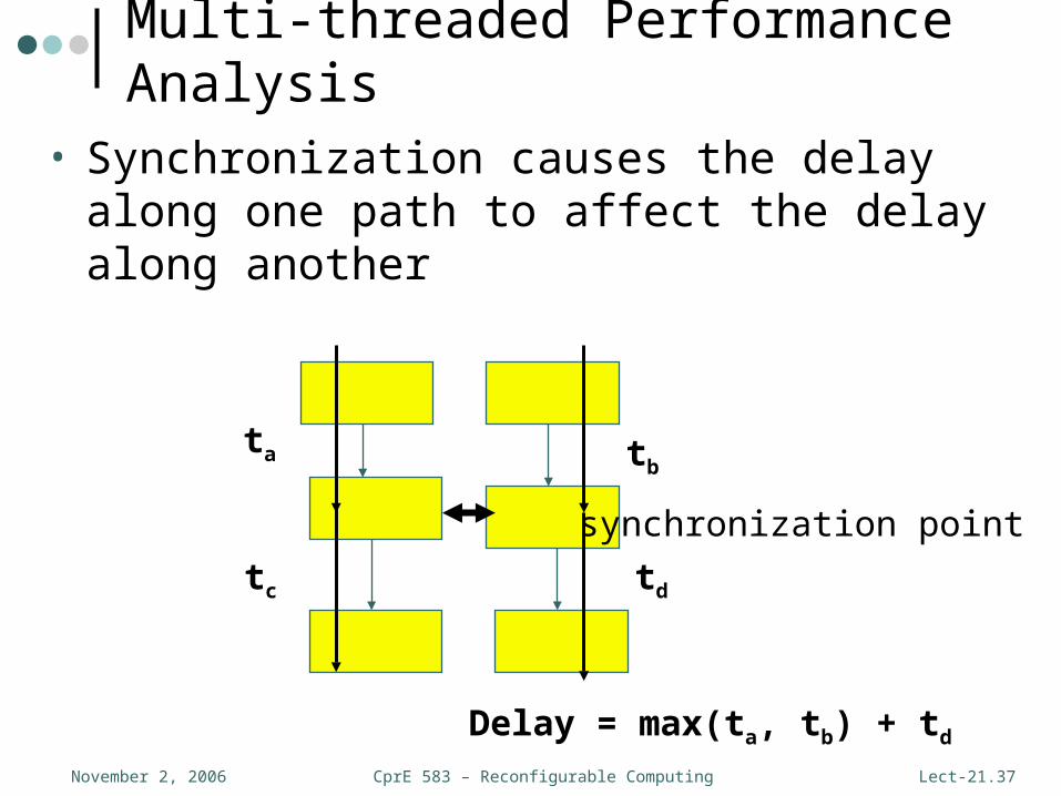
Multi-threaded Performance Analysis
• Synchronization causes the delay along one path to affect the delay along another
synchronization point
ta tb
tc td
Delay = max(ta, tb) + td
CprE 583 – Reconfigurable ComputingNovember 2, 2006 Lect-21.38
Control
• Need to signal between CPU and accelerator• Data ready• Complete
• Implementations:• Shared memory• Handshake
• If computation time is very predictable, a simpler communication scheme may be possible
CprE 583 – Reconfigurable ComputingNovember 2, 2006 Lect-21.39
Application Program
Operating System
I/O driver
I/O bus
Application hardware (custom)
I/O driver
I/O bus
Send, Receive, Wait
Register reads/writes
Interrupt service
Bus transactionsInterrupts
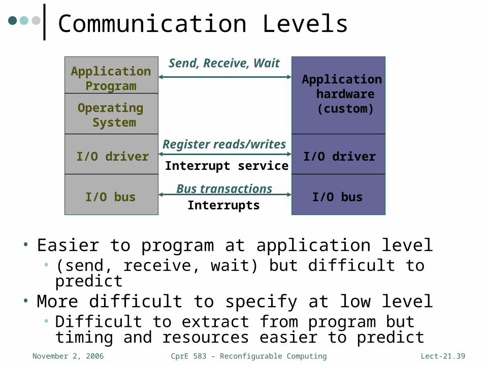
Communication Levels
• Easier to program at application level• (send, receive, wait) but difficult to predict
• More difficult to specify at low level• Difficult to extract from program but timing and
resources easier to predict
CprE 583 – Reconfigurable ComputingNovember 2, 2006 Lect-21.40
d1
d2d3
p1 p2 p3
r2
r3
FPGAControl/Data FIFO
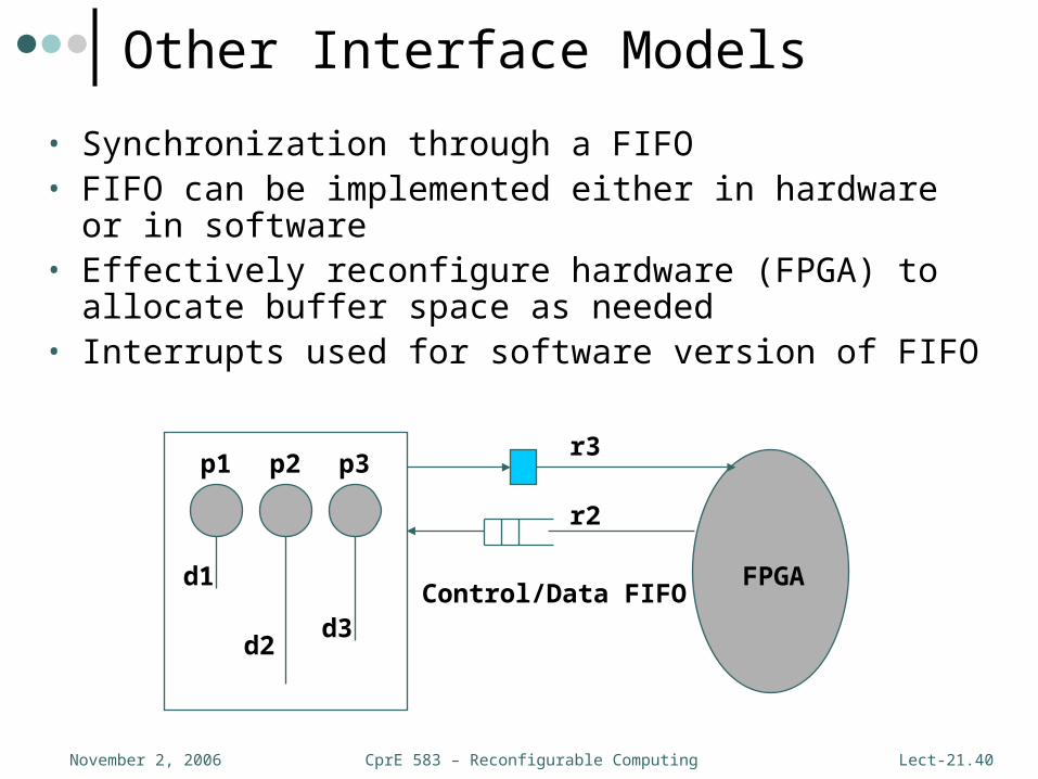
Other Interface Models
• Synchronization through a FIFO• FIFO can be implemented either in hardware or in
software• Effectively reconfigure hardware (FPGA) to allocate
buffer space as needed• Interrupts used for software version of FIFO
CprE 583 – Reconfigurable ComputingNovember 2, 2006 Lect-21.41
Debugging
• Hard to test a CPU/accelerator system:• Hard to control and observe the accelerator
without the CPU• Software on CPU may have bugs
• Build separate test benches for CPU code, accelerator
• Test integrated system after components have been tested

CprE 583 – Reconfigurable ComputingNovember 2, 2006 Lect-21.42
Graphical EFSMGraphical EFSM ESTERELESTEREL ................................
CompilersCompilers
PartitioningPartitioning
Sw SynthesisSw Synthesis
FormalFormal
VerificationVerification
Sw Code + Sw Code +
RTOSRTOSLogic NetlistLogic NetlistSimulationSimulation
Hw SynthesisHw SynthesisIntfc + RTOSIntfc + RTOS
SynthesisSynthesis
CFSMsCFSMs
Rapid prototypingRapid prototyping
POLIS Codesign Methodology

CprE 583 – Reconfigurable ComputingNovember 2, 2006 Lect-21.43
Codesign Finite State Machines
• POLIS uses an FSM model for• Uncommitted• Synthesizable• VerifiableControl-dominated HW/SW specification
• Translators from • State diagrams, • Esterel, ECL, ReactiveJava• HDLsInto a single FSM-based language

CprE 583 – Reconfigurable ComputingNovember 2, 2006 Lect-21.44
CFSM behavior
• Four-phase cycle: Idle Detect input events Execute one transition Emit output events
• Software response could take a long time:• Unbounded delay assumption
• Need efficient hw/sw communication primitive:• Event-based point-to-point communication

CprE 583 – Reconfigurable ComputingNovember 2, 2006 Lect-21.45
CFSM2CFSM2
CFSM3CFSM3
C=>GC=>G
CFSM1CFSM1
C=>FC=>FB=>CB=>C
F^(G==1)F^(G==1)
(A==0)=>B(A==0)=>B
C=>AC=>ACFSM1CFSM1 CFSM2CFSM2
C=>BC=>B
FF
GG
CCCC
BBAA
C=>GC=>G
C=>BC=>B
• Globally Asynchronous, Locally Synchronous (GALS) model
Network of CFSMs
CprE 583 – Reconfigurable ComputingNovember 2, 2006 Lect-21.46
Summary
• Hardware/software codesign complicated and limited by performance estimates
• Algorithms not generally as good as human partitioning
• Other interesting issues include dual processors, special memory interfaces
• Will likely evolve at faster rate as compilers evolve