cpkJNMMQ - Rentex
246
rëÉêÛë dìáÇÉ cpkJNMMQ • Manual #: 26-0702200-00 • Revision: 00
Transcript of cpkJNMMQ - Rentex

rëÉêÛë=dìáÇÉ
cpkJNMMQ
• Manual #: 26-0702200-00
• Revision: 00

cpkJNMMQ==√==rëÉêÛë=dìáÇÉ
`çéóêáÖÜí© Barco. March 21, 2013
All rights reserved. No part of this document may be copied, reproduced or translated. It shall not otherwise be recorded, transmitted or stored in a retrieval system without the prior written consent of Barco.
kçíáÅÉBarco provides this manual “as is” without warranty of any kind, either expressed or implied, including but not limited to the implied warranties or merchantability and fitness for a particular purpose. Barco may make improvements and/or changes to the product(s) and/or the program(s) described in this publication at any time without notice.
This publication could contain technical inaccuracies or typographical errors. Changes are periodically made to the information in this publication; these changes are incorporated in new editions of this publication.
cÉÇÉê~ä=`çããìåáÅ~íáçåë=`çããáëëáçå=Ec``F=pí~íÉãÉåíThis equipment has been tested and found to comply with the limits for a class A digital device, pursuant to Part 15 of the FCC rules. These limits are designed to provide reasonable protection against harmful interference when the equipment is operated in a commercial environment. This equipment generates, uses, and can radiate radio frequency energy and, if not installed and used in accordance with the instruction manual, may cause harmful interference to radio communications. Operation of this equipment in a residential area may cause harmful interference, in which case the user will be responsible for correcting any interference.
dì~ê~åíÉÉ=~åÇ=`çãéÉåë~íáçåBarco provides a guarantee relating to perfect manufacturing as part of the legally stipulated terms of guarantee. On receipt, the purchaser must immediately inspect all delivered goods for damage incurred during transport, as well as for material and manufacturing faults Barco must be informed immediately in writing of any complaints.
The period of guarantee begins on the date of transfer of risks, in the case of special systems and software on the date of commissioning, at latest 30 days after the transfer of risks. In the event of justified notice of compliant, Barco can repair the fault or provide a replacement at its own discretion within an appropriate period. If this measure proves to be impossible or unsuccessful, the purchaser can demand a reduction in the purchase price or cancellation of the contract. All other claims, in particular those relating to compensation for direct or indirect damage, and also damage attributed to the operation of software as well as to other services provided by Barco, being a component of the system or independent service, will be deemed invalid provided the damage is not proven to be attributed to the absence of properties guaranteed in writing or due to the intent or gross negligence or part of Barco.
If the purchaser or a third party carries out modifications or repairs on goods delivered by Barco, or if the goods are handled incorrectly, in particular if the systems are commissioned operated incorrectly or if, after the transfer of risks, the goods are subject to influences not
2 FSN-1004 • User’s Guide • Rev 00

agreed upon in the contract, all guarantee claims of the purchaser will be rendered invalid. Not included in the guarantee coverage are system failures which are attributed to programs or special electronic circuitry provided by the purchaser, e.g. interfaces. Normal wear as well as normal maintenance are not subject to the guarantee provided by Barco either.
The environmental conditions as well as the servicing and maintenance regulations specified in this manual must be complied with by the customer.
qê~ÇÉã~êâëBrand and product names mentioned in this manual may be trademarks, registered trademarks or copyrights of their respective holders. All brand and product names mentioned in this manual serve as comments or examples and are not to be understood as advertising for the products or their manufactures.
`çãé~åó=^ÇÇêÉëë
Barco, Inc.11101 Trade Center DriveRancho Cordova, California 95670USA
• Phone: (916) 859-2500
• Fax: (916) 859-2515
• Website: www.barco.com
Barco N.V. Noordlaan 58520 KuurneBELGIUM
• Phone: +32 56.36.82.11
• Fax: +32 56.35.16.51
Technical Support
• Customer Service Portal — www.barco.com/esupport
• (866) 374-7878 — Events (24/7)
• (866) 469-8036 — Digital Cinema (24/7)
FSN-1004 • User’s Guide • Rev 00 3

léÉê~íçêë=p~ÑÉíó=pìãã~êóThe general safety information in this summary is for operating personnel.
aç=kçí=oÉãçîÉ=`çîÉêë=çê=m~åÉäëThere are no user-serviceable parts within the unit. Removal of the top cover will expose dangerous voltages. To avoid personal injury, do not remove the top cover. Do not operate the unit without the cover installed.
mçïÉê=pçìêÅÉThis product is intended to operate from a power source that will not apply more than 230 volts rms between the supply conductors or between both supply conductor and ground. A protective ground connection by way of grounding conductor in the power cord is essential for safe operation.
dêçìåÇáåÖ=íÜÉ=mêçÇìÅíThis product is grounded through the grounding conductor of the power cord. To avoid electrical shock, plug the power cord into a properly wired receptacle before connecting to the product input or output terminals. A protective-ground connection by way of the grounding conductor in the power cord is essential for safe operation.
rëÉ=íÜÉ=mêçéÉê=mçïÉê=`çêÇUse only the power cord and connector specified for your product. Use only a power cord that is in good condition. Refer cord and connector changes to qualified service personnel.
rëÉ=íÜÉ=mêçéÉê=cìëÉTo avoid fire hazard, use only the fuse having identical type, voltage rating, and current rating characteristics. Refer fuse replacement to qualified service personnel.
aç=kçí=léÉê~íÉ=áå=bñéäçëáîÉ=^íãçëéÜÉêÉëTo avoid explosion, do not operate this product in an explosive atmosphere.
4 FSN-1004 • User’s Guide • Rev 00

qÉêãë=få=qÜáë=j~åì~ä=~åÇ=bèìáéãÉåí=j~êâáåÖ=
t^okfkdHighlights an operating procedure, practice, condition, statement, etc., which, if not strictly observed, could result in injury to or death of personnel.
`^rqflkThe exclamation point within an equilateral triangle is intended to alert the user to the presence of important operating and maintenance (servicing) instructions in the literature accompanying the appliance.
^sboqfppbjbkq>Le point d´exclamation dans un triangle equilatéral signale à alerter l´utilisateur qu´il y a des instructions d´operation et d´entretien tres importantes dans la litérature qui accompagne l´appareil.
slopf`eqEin Ausrufungszeichen innerhalb eines gleichwinkeligen Dreiecks dient dazu, den Benutzer auf wichtige Bedienungs-und Wartungsanweisungen in der Dem Great beiliegenden Literatur aufmerksam zu machen.
Note Highlights an essential operating procedure, condition or statement.
FSN-1004 • User’s Guide • Rev 00 5

`Ü~åÖÉ=eáëíçêóThe table below lists the changes to the FSN-1004 User’s Guide.
Table 0-1. Change History
Rev Date ECP # Description Approved By
00 3/21/13 604387 FSN-1004 User’s Guide R. Pellicano
6 FSN-1004 • User’s Guide • Rev 00

q~ÄäÉ=çÑ=`çåíÉåíë
`Ü~éíÉê=N fåíêçÇìÅíáçå =K=K=K=K=K=K=K=K=K=K=K=K=K=K=K=K=K=K=K=K=K=K=K=K=K=K=K=K=K=K=K=K=K=K=K=K=K=K=K=K=K=NPIn This Chapter . . . . . . . . . . . . . . . . . . . . . . . . . . . . . . . . . . . . . . . . . . . . . . . . 13Software Version . . . . . . . . . . . . . . . . . . . . . . . . . . . . . . . . . . . . . . . . . . . . . . 14Chapter Structure . . . . . . . . . . . . . . . . . . . . . . . . . . . . . . . . . . . . . . . . . . . . . . 14How to Use This Guide. . . . . . . . . . . . . . . . . . . . . . . . . . . . . . . . . . . . . . . . . . 15
Navigating . . . . . . . . . . . . . . . . . . . . . . . . . . . . . . . . . . . . . . . . . . . . . . 15Table of Contents and Index . . . . . . . . . . . . . . . . . . . . . . . . . . . . . . . . 15
Conventions . . . . . . . . . . . . . . . . . . . . . . . . . . . . . . . . . . . . . . . . . . . . . . . . . . 15Glossary of Switcher Terms . . . . . . . . . . . . . . . . . . . . . . . . . . . . . . . . . . . . . . 16About the FSN-1004. . . . . . . . . . . . . . . . . . . . . . . . . . . . . . . . . . . . . . . . . . . . 18
Overview . . . . . . . . . . . . . . . . . . . . . . . . . . . . . . . . . . . . . . . . . . . . . . . 18Control GUI . . . . . . . . . . . . . . . . . . . . . . . . . . . . . . . . . . . . . . . . . . . . . 19System Configuration . . . . . . . . . . . . . . . . . . . . . . . . . . . . . . . . . . . . . 20
FSN-1004 System . . . . . . . . . . . . . . . . . . . . . . . . . . . . . . . . . 20FSN-1004 Cards . . . . . . . . . . . . . . . . . . . . . . . . . . . . . . . . . . 20
Connectivity Diagrams . . . . . . . . . . . . . . . . . . . . . . . . . . . . . . . . . . . . . . . . . . 21System 1 — Single Screen . . . . . . . . . . . . . . . . . . . . . . . . . . . . . . . . . 21System 2 — Multiple Destinations . . . . . . . . . . . . . . . . . . . . . . . . . . . . 22
Application Questions. . . . . . . . . . . . . . . . . . . . . . . . . . . . . . . . . . . . . . . . . . . 23
`Ü~éíÉê=O cpkJNMMQ=lêáÉåí~íáçå =K=K=K=K=K=K=K=K=K=K=K=K=K=K=K=K=K=K=K=K=K=K=K=K=K=K=K=K=K=K=K=ORIn This Chapter . . . . . . . . . . . . . . . . . . . . . . . . . . . . . . . . . . . . . . . . . . . . . . . . 25Hardware Description . . . . . . . . . . . . . . . . . . . . . . . . . . . . . . . . . . . . . . . . . . . 26
Chassis Overview . . . . . . . . . . . . . . . . . . . . . . . . . . . . . . . . . . . . . . . . 26Card Slot Allocation . . . . . . . . . . . . . . . . . . . . . . . . . . . . . . . . . . . . . . . 27Chassis Front Door . . . . . . . . . . . . . . . . . . . . . . . . . . . . . . . . . . . . . . . 28
Air Filter . . . . . . . . . . . . . . . . . . . . . . . . . . . . . . . . . . . . . . . . . 29Door Removal and Re-installation. . . . . . . . . . . . . . . . . . . . . 29
Chassis Front. . . . . . . . . . . . . . . . . . . . . . . . . . . . . . . . . . . . . . . . . . . . 30Chassis Rear . . . . . . . . . . . . . . . . . . . . . . . . . . . . . . . . . . . . . . . . . . . . 32
Card Descriptions . . . . . . . . . . . . . . . . . . . . . . . . . . . . . . . . . . . . . . . . . . . . . . 34System Card . . . . . . . . . . . . . . . . . . . . . . . . . . . . . . . . . . . . . . . . . . . . 35
Ethernet Connections . . . . . . . . . . . . . . . . . . . . . . . . . . . . . . 38M/E Card . . . . . . . . . . . . . . . . . . . . . . . . . . . . . . . . . . . . . . . . . . . . . . . 39Universal Input Card . . . . . . . . . . . . . . . . . . . . . . . . . . . . . . . . . . . . . . 41Standard Output Card . . . . . . . . . . . . . . . . . . . . . . . . . . . . . . . . . . . . . 43Multiviewer Card . . . . . . . . . . . . . . . . . . . . . . . . . . . . . . . . . . . . . . . . . 45
Card LEDs . . . . . . . . . . . . . . . . . . . . . . . . . . . . . . . . . . . . . . . . . . . . . . . . . . . 47Analog Format Connection Table. . . . . . . . . . . . . . . . . . . . . . . . . . . . . . . . . . 48
FSN-1004 • User’s Guide • Rev 00 7

Table of Contents
`Ü~éíÉê=P fåëí~ää~íáçå =K=K=K=K=K=K=K=K=K=K=K=K=K=K=K=K=K=K=K=K=K=K=K=K=K=K=K=K=K=K=K=K=K=K=K=K=K=K=K=K=K=K=QVIn This Chapter . . . . . . . . . . . . . . . . . . . . . . . . . . . . . . . . . . . . . . . . . . . . . . . . 49Safety Precautions . . . . . . . . . . . . . . . . . . . . . . . . . . . . . . . . . . . . . . . . . . . . . 50Shipping Information. . . . . . . . . . . . . . . . . . . . . . . . . . . . . . . . . . . . . . . . . . . . 50Unpacking and Inspection . . . . . . . . . . . . . . . . . . . . . . . . . . . . . . . . . . . . . . . 50Site Preparation . . . . . . . . . . . . . . . . . . . . . . . . . . . . . . . . . . . . . . . . . . . . . . . 50Cable and Adapter Information. . . . . . . . . . . . . . . . . . . . . . . . . . . . . . . . . . . . 50PC Connection . . . . . . . . . . . . . . . . . . . . . . . . . . . . . . . . . . . . . . . . . . . . . . . . 52FSN-1004 Rack-Mount Procedure . . . . . . . . . . . . . . . . . . . . . . . . . . . . . . . . . 53System Connections. . . . . . . . . . . . . . . . . . . . . . . . . . . . . . . . . . . . . . . . . . . . 55
Power Cord/Line Voltage Selection . . . . . . . . . . . . . . . . . . . . . . . . . . . 58Card and Rear Panel . . . . . . . . . . . . . . . . . . . . . . . . . . . . . . . . . . . . . . . . . . . 59
Rear Panel Insertion . . . . . . . . . . . . . . . . . . . . . . . . . . . . . . . . . . . . . . 60Rear Panel Removal . . . . . . . . . . . . . . . . . . . . . . . . . . . . . . . . . . . . . . 60Card Insertion . . . . . . . . . . . . . . . . . . . . . . . . . . . . . . . . . . . . . . . . . . . 61Card Removal . . . . . . . . . . . . . . . . . . . . . . . . . . . . . . . . . . . . . . . . . . . 63
Signal Connections. . . . . . . . . . . . . . . . . . . . . . . . . . . . . . . . . . . . . . . . . . . . . 64Output Connections . . . . . . . . . . . . . . . . . . . . . . . . . . . . . . . . . . . . . . . 65Universal Input Connections . . . . . . . . . . . . . . . . . . . . . . . . . . . . . . . . 66
Analog Format Connection Table . . . . . . . . . . . . . . . . . . . . . 67Multiviewer Connections . . . . . . . . . . . . . . . . . . . . . . . . . . . . . . . . . . . 68
`Ü~éíÉê=Q jÉåì=lêáÉåí~íáçå=K=K=K=K=K=K=K=K=K=K=K=K=K=K=K=K=K=K=K=K=K=K=K=K=K=K=K=K=K=K=K=K=K=K=K=K=SVIn This Chapter . . . . . . . . . . . . . . . . . . . . . . . . . . . . . . . . . . . . . . . . . . . . . . . . 69Menu Tree . . . . . . . . . . . . . . . . . . . . . . . . . . . . . . . . . . . . . . . . . . . . . . . . . . . 70
High-Level Menu Tree . . . . . . . . . . . . . . . . . . . . . . . . . . . . . . . . . . . . . 70System Menu Tree . . . . . . . . . . . . . . . . . . . . . . . . . . . . . . . . . . . . . . . 71
Using the Menu System . . . . . . . . . . . . . . . . . . . . . . . . . . . . . . . . . . . . . . . . . 72Buttons, Tables and Matrices . . . . . . . . . . . . . . . . . . . . . . . . . . . . . . . . . . . . . 74
Button Categories and Colors . . . . . . . . . . . . . . . . . . . . . . . . . . . . . . . 74Latching, Momentary and Conditional Buttons . . . . . . . . . . . . . . . . . . 75Value Buttons . . . . . . . . . . . . . . . . . . . . . . . . . . . . . . . . . . . . . . . . . . . 76Toggle Buttons. . . . . . . . . . . . . . . . . . . . . . . . . . . . . . . . . . . . . . . . . . . 76Pop-up Buttons . . . . . . . . . . . . . . . . . . . . . . . . . . . . . . . . . . . . . . . . . . 77Location Buttons . . . . . . . . . . . . . . . . . . . . . . . . . . . . . . . . . . . . . . . . . 77Summary of Button Types . . . . . . . . . . . . . . . . . . . . . . . . . . . . . . . . . . 79Tables . . . . . . . . . . . . . . . . . . . . . . . . . . . . . . . . . . . . . . . . . . . . . . . . . 80Matrices . . . . . . . . . . . . . . . . . . . . . . . . . . . . . . . . . . . . . . . . . . . . . . . . 81Notes and Error Messages . . . . . . . . . . . . . . . . . . . . . . . . . . . . . . . . . 81
Using the Keypad . . . . . . . . . . . . . . . . . . . . . . . . . . . . . . . . . . . . . . . . . . . . . . 82Using the Pop-up Keyboard . . . . . . . . . . . . . . . . . . . . . . . . . . . . . . . . . . . . . . 85Memory Menu. . . . . . . . . . . . . . . . . . . . . . . . . . . . . . . . . . . . . . . . . . . . . . . . . 86
Memory Menu Access . . . . . . . . . . . . . . . . . . . . . . . . . . . . . . . . . . . . . 87Memory Menu Description. . . . . . . . . . . . . . . . . . . . . . . . . . . . . . . . . . 88
Memory Menu in View Mode. . . . . . . . . . . . . . . . . . . . . . . . . 88Memory Menu in Store Mode . . . . . . . . . . . . . . . . . . . . . . . . 90Memory Menu in Recall Mode. . . . . . . . . . . . . . . . . . . . . . . . 91
Enables Menu Description. . . . . . . . . . . . . . . . . . . . . . . . . . . . . . . . . . 92Enable Descriptions . . . . . . . . . . . . . . . . . . . . . . . . . . . . . . . 94
System Enables . . . . . . . . . . . . . . . . . . . . . . . . . . . 94Out Enables . . . . . . . . . . . . . . . . . . . . . . . . . . . . . . 94
8 FSN-1004 • User’s Guide • Rev 00

Table of Contents
Selecting Registers . . . . . . . . . . . . . . . . . . . . . . . . . . . . . . . . . . . . . . . 95Naming Registers . . . . . . . . . . . . . . . . . . . . . . . . . . . . . . . . . . . . . . . . 95Advanced Memory Functions . . . . . . . . . . . . . . . . . . . . . . . . . . . . . . . 95
Keyboard Shortcuts. . . . . . . . . . . . . . . . . . . . . . . . . . . . . . . . 96Deleting Registers . . . . . . . . . . . . . . . . . . . . . . . . . . . . . . . . . 97Locking and Unlocking Registers . . . . . . . . . . . . . . . . . . . . . 97
Stills Menu . . . . . . . . . . . . . . . . . . . . . . . . . . . . . . . . . . . . . . . . . . . . . . . . . . . 99Stills Menu Access. . . . . . . . . . . . . . . . . . . . . . . . . . . . . . . . . . . . . . . . 99Stills Menu Description . . . . . . . . . . . . . . . . . . . . . . . . . . . . . . . . . . . . 99
Stills Menu Capture Mode . . . . . . . . . . . . . . . . . . . . . . . . . . . 99Summary of Stills Capture Method . . . . . . . . . . . . 103
Still Menu Recall Mode . . . . . . . . . . . . . . . . . . . . . . . . . . . . 103Summary of Stills Recall Method . . . . . . . . . . . . . 104
Screens Menu . . . . . . . . . . . . . . . . . . . . . . . . . . . . . . . . . . . . . . . . . . . . . . . 105System Menu . . . . . . . . . . . . . . . . . . . . . . . . . . . . . . . . . . . . . . . . . . . . . . . . 107
System Menu Description . . . . . . . . . . . . . . . . . . . . . . . . . . . . . . . . . 108System Menu Access . . . . . . . . . . . . . . . . . . . . . . . . . . . . . 108System Menu Functions . . . . . . . . . . . . . . . . . . . . . . . . . . . 109Status Tables . . . . . . . . . . . . . . . . . . . . . . . . . . . . . . . . . . . 110
Communications Setup Menu . . . . . . . . . . . . . . . . . . . . . . . . . . . . . . 112Input Setup . . . . . . . . . . . . . . . . . . . . . . . . . . . . . . . . . . . . . . . . . . . . 117
Rear I/O View Description . . . . . . . . . . . . . . . . . . . . . . . . . . 118Connector Colors . . . . . . . . . . . . . . . . . . . . . . . . . . . . . . . . 119Input Table Description . . . . . . . . . . . . . . . . . . . . . . . . . . . . 120Input Menu Functions . . . . . . . . . . . . . . . . . . . . . . . . . . . . . 121
Default Naming Conventions . . . . . . . . . . . . . . . . 122Input Setup Menu . . . . . . . . . . . . . . . . . . . . . . . . . . . . . . . . 123
Input Capture and Process Panel . . . . . . . . . . . . . 124Input Capture and Timing Section . . . . . 124Input Processing Section . . . . . . . . . . . . 128
Input Sizing and Scaling Panel . . . . . . . . . . . . . . . 129Input Color Correction Section . . . . . . . . . . . . . . . 135
Input Setup Menu Tool Bar Functions. . . . . . . . . . . . . . . . . 136Multiviewer Setup Menu . . . . . . . . . . . . . . . . . . . . . . . . . . . . . . . . . . 137Output Setup Menu . . . . . . . . . . . . . . . . . . . . . . . . . . . . . . . . . . . . . . 138
Rear I/O View Description . . . . . . . . . . . . . . . . . . . . . . . . . . 139Aux Table Description . . . . . . . . . . . . . . . . . . . . . . . . . . . . . 139Aux Mixer Description . . . . . . . . . . . . . . . . . . . . . . . . . . . . . 140Output Setup Menu Functions. . . . . . . . . . . . . . . . . . . . . . . 140SOC Setup Menu . . . . . . . . . . . . . . . . . . . . . . . . . . . . . . . . 141
Output and Process Panel . . . . . . . . . . . . . . . . . . 142Output Section . . . . . . . . . . . . . . . . . . . . 142Output Processing Section . . . . . . . . . . . 143Output Status Section. . . . . . . . . . . . . . . 143Output and Process Tool Bar Functions. 144Advanced SOC Output Setup Menu. . . . 145
Output Sizing and Scaling Panel . . . . . . . . . . . . . 146Output Color Correction Panel . . . . . . . . . . . . . . . 150
User Preferences Menu. . . . . . . . . . . . . . . . . . . . . . . . . . . . . . . . . . . 151User Preferences Table . . . . . . . . . . . . . . . . . . . . . . . . . . . 152User Preferences Functions . . . . . . . . . . . . . . . . . . . . . . . . 152
Software Menu. . . . . . . . . . . . . . . . . . . . . . . . . . . . . . . . . . . . . . . . . . 153Software Table . . . . . . . . . . . . . . . . . . . . . . . . . . . . . . . . . . 154Software Functions . . . . . . . . . . . . . . . . . . . . . . . . . . . . . . . 154
FSN-1004 • User’s Guide • Rev 00 9

Table of Contents
Output Test Patterns Menu . . . . . . . . . . . . . . . . . . . . . . . . . . . . . . . . 156Lock/Unlock GUI . . . . . . . . . . . . . . . . . . . . . . . . . . . . . . . . . . . . . . . . 158Save All . . . . . . . . . . . . . . . . . . . . . . . . . . . . . . . . . . . . . . . . . . . . . . . 158Backup and Restore Menu . . . . . . . . . . . . . . . . . . . . . . . . . . . . . . . . 160Reset Menu . . . . . . . . . . . . . . . . . . . . . . . . . . . . . . . . . . . . . . . . . . . . 161
Factory Default Settings . . . . . . . . . . . . . . . . . . . . . . . . . . . 162
`Ü~éíÉê=R póëíÉã=pÉíìéK=K=K=K=K=K=K=K=K=K=K=K=K=K=K=K=K=K=K=K=K=K=K=K=K=K=K=K=K=K=K=K=K=K=K=K=K=K=KNSPIn This Chapter . . . . . . . . . . . . . . . . . . . . . . . . . . . . . . . . . . . . . . . . . . . . . . . 163Setup Prerequisites . . . . . . . . . . . . . . . . . . . . . . . . . . . . . . . . . . . . . . . . . . . 164System Setup Sequence . . . . . . . . . . . . . . . . . . . . . . . . . . . . . . . . . . . . . . . 165Power Up and Status Check . . . . . . . . . . . . . . . . . . . . . . . . . . . . . . . . . . . . 166Return to Factory Default . . . . . . . . . . . . . . . . . . . . . . . . . . . . . . . . . . . . . . . 167Communications Setup . . . . . . . . . . . . . . . . . . . . . . . . . . . . . . . . . . . . . . . . 168Restoring the System . . . . . . . . . . . . . . . . . . . . . . . . . . . . . . . . . . . . . . . . . . 169Output Format Setup . . . . . . . . . . . . . . . . . . . . . . . . . . . . . . . . . . . . . . . . . . 170Output Test Patterns . . . . . . . . . . . . . . . . . . . . . . . . . . . . . . . . . . . . . . . . . . 171Universal Input Setup . . . . . . . . . . . . . . . . . . . . . . . . . . . . . . . . . . . . . . . . . . 172Aux Output Setup . . . . . . . . . . . . . . . . . . . . . . . . . . . . . . . . . . . . . . . . . . . . . 175Multiviewer Setup . . . . . . . . . . . . . . . . . . . . . . . . . . . . . . . . . . . . . . . . . . . . . 178User Preferences Setup . . . . . . . . . . . . . . . . . . . . . . . . . . . . . . . . . . . . . . . . 180Saving the Setup . . . . . . . . . . . . . . . . . . . . . . . . . . . . . . . . . . . . . . . . . . . . . 181Backing up the System. . . . . . . . . . . . . . . . . . . . . . . . . . . . . . . . . . . . . . . . . 181
`Ü~éíÉê=S léÉê~íáçåë =K=K=K=K=K=K=K=K=K=K=K=K=K=K=K=K=K=K=K=K=K=K=K=K=K=K=K=K=K=K=K=K=K=K=K=K=K=K=K=K=KNUPIn This Chapter . . . . . . . . . . . . . . . . . . . . . . . . . . . . . . . . . . . . . . . . . . . . . . . 183Quick Setup and Operations . . . . . . . . . . . . . . . . . . . . . . . . . . . . . . . . . . . . 184Quick Function Reference . . . . . . . . . . . . . . . . . . . . . . . . . . . . . . . . . . . . . . 186Understanding Error Messages . . . . . . . . . . . . . . . . . . . . . . . . . . . . . . . . . . 186Working with Pop-ups. . . . . . . . . . . . . . . . . . . . . . . . . . . . . . . . . . . . . . . . . . 188Using the Keypad . . . . . . . . . . . . . . . . . . . . . . . . . . . . . . . . . . . . . . . . . . . . . 188Working with Memory Registers. . . . . . . . . . . . . . . . . . . . . . . . . . . . . . . . . . 189
Memory Register Overview . . . . . . . . . . . . . . . . . . . . . . . . . . . . . . . . 189Storing Memory Registers . . . . . . . . . . . . . . . . . . . . . . . . . . . . . . . . . 190
Store, Set Enables, Enter Custom Name . . . . . . . . . . . . . . 190Memory Store Notes . . . . . . . . . . . . . . . . . . . . . . . . . . . . . . 191
Recalling Memory Registers . . . . . . . . . . . . . . . . . . . . . . . . . . . . . . . 192Recall, Bypass Enables. . . . . . . . . . . . . . . . . . . . . . . . . . . . 192Recall, Adjust Enables . . . . . . . . . . . . . . . . . . . . . . . . . . . . 192Memory Recall Notes . . . . . . . . . . . . . . . . . . . . . . . . . . . . . 193
Viewing Memory Registers . . . . . . . . . . . . . . . . . . . . . . . . . . . . . . . . 194Locking and Unlocking Memory Registers . . . . . . . . . . . . . . . . . . . . 194Deleting Memory Registers . . . . . . . . . . . . . . . . . . . . . . . . . . . . . . . . 195Assigning a Keyboard Shortcut to a Memory Register . . . . . . . . . . . 195
Backing Up and Restoring the System. . . . . . . . . . . . . . . . . . . . . . . . . . . . . 196Backing Up the System . . . . . . . . . . . . . . . . . . . . . . . . . . . . . . . . . . . 196Restoring the System . . . . . . . . . . . . . . . . . . . . . . . . . . . . . . . . . . . . 196
10 FSN-1004 • User’s Guide • Rev 00

Table of Contents
`Ü~éíÉê=T jìäíáîáÉïÉê=léÉê~íáçåë =K=K=K=K=K=K=K=K=K=K=K=K=K=K=K=K=K=K=K=K=K=K=K=K=K=K=K=K=KNVTIn This Chapter . . . . . . . . . . . . . . . . . . . . . . . . . . . . . . . . . . . . . . . . . . . . . . . 197Introduction to the Multiviewer . . . . . . . . . . . . . . . . . . . . . . . . . . . . . . . . . . . 198Multiviewer Menu Orientation . . . . . . . . . . . . . . . . . . . . . . . . . . . . . . . . . . . . 200
Multiviewer Setup Menu . . . . . . . . . . . . . . . . . . . . . . . . . . . . . . . . . . 201Multiviewer Output Setup Menu. . . . . . . . . . . . . . . . . . . . . . . . . . . . . 203Select Layout Menu . . . . . . . . . . . . . . . . . . . . . . . . . . . . . . . . . . . . . . 204Select Colors Menu . . . . . . . . . . . . . . . . . . . . . . . . . . . . . . . . . . . . . . 208Clock Setup Menu . . . . . . . . . . . . . . . . . . . . . . . . . . . . . . . . . . . . . . . 209Assign Source Keypad . . . . . . . . . . . . . . . . . . . . . . . . . . . . . . . . . . . 212
Multiviewer Setup . . . . . . . . . . . . . . . . . . . . . . . . . . . . . . . . . . . . . . . . . . . . . 213Multiviewer Memory . . . . . . . . . . . . . . . . . . . . . . . . . . . . . . . . . . . . . . . . . . . 213
`Ü~éíÉê=U réÇ~íáåÖ=pçÑíï~êÉ K=K=K=K=K=K=K=K=K=K=K=K=K=K=K=K=K=K=K=K=K=K=K=K=K=K=K=K=K=K=K=K=K=KONRIn This Chapter . . . . . . . . . . . . . . . . . . . . . . . . . . . . . . . . . . . . . . . . . . . . . . . 215Software Update Overview. . . . . . . . . . . . . . . . . . . . . . . . . . . . . . . . . . . . . . 216Hardware Requirements. . . . . . . . . . . . . . . . . . . . . . . . . . . . . . . . . . . . . . . . 216Downloading Software . . . . . . . . . . . . . . . . . . . . . . . . . . . . . . . . . . . . . . . . . 217
Via FTP Site. . . . . . . . . . . . . . . . . . . . . . . . . . . . . . . . . . . . . . . . . . . . 217Via Web Site . . . . . . . . . . . . . . . . . . . . . . . . . . . . . . . . . . . . . . . . . . . 218
Updating FSN-1400 Software. . . . . . . . . . . . . . . . . . . . . . . . . . . . . . . . . . . . 219
^ééÉåÇáñ=^= péÉÅáÑáÅ~íáçåëK=K=K=K=K=K=K=K=K=K=K=K=K=K=K=K=K=K=K=K=K=K=K=K=K=K=K=K=K=K=K=K=K=K=K=K=K=K=KOON
In This Appendix. . . . . . . . . . . . . . . . . . . . . . . . . . . . . . . . . . . . . . . . . . . . . . 221System Specifications Overview . . . . . . . . . . . . . . . . . . . . . . . . . . . . . . . . . 222Reference Video Output Specifications . . . . . . . . . . . . . . . . . . . . . . . . . . . . 223Physical and Electrical Specifications . . . . . . . . . . . . . . . . . . . . . . . . . . . . . 224Communications Specifications . . . . . . . . . . . . . . . . . . . . . . . . . . . . . . . . . . 225Agency Specifications . . . . . . . . . . . . . . . . . . . . . . . . . . . . . . . . . . . . . . . . . 225Cable Specifications . . . . . . . . . . . . . . . . . . . . . . . . . . . . . . . . . . . . . . . . . . . 225Delay Specifications . . . . . . . . . . . . . . . . . . . . . . . . . . . . . . . . . . . . . . . . . . . 226Pinouts . . . . . . . . . . . . . . . . . . . . . . . . . . . . . . . . . . . . . . . . . . . . . . . . . . . . . 227
Analog 15-pin D Connector . . . . . . . . . . . . . . . . . . . . . . . . . . . . . . . . 227DVI-I Connector . . . . . . . . . . . . . . . . . . . . . . . . . . . . . . . . . . . . . . . . . 228Ethernet Connector . . . . . . . . . . . . . . . . . . . . . . . . . . . . . . . . . . . . . . 229Serial Connectors . . . . . . . . . . . . . . . . . . . . . . . . . . . . . . . . . . . . . . . 230
Output Format Tables. . . . . . . . . . . . . . . . . . . . . . . . . . . . . . . . . . . . . . . . . . 231Output Formats . . . . . . . . . . . . . . . . . . . . . . . . . . . . . . . . . . . . . . . . . 231
^ééÉåÇáñ=_= `çåí~Åí=fåÑçêã~íáçå=K=K=K=K=K=K=K=K=K=K=K=K=K=K=K=K=K=K=K=K=K=K=K=K=K=K=K=K=K=K=K=K=KOPP
In This Appendix. . . . . . . . . . . . . . . . . . . . . . . . . . . . . . . . . . . . . . . . . . . . . . 233Warranty . . . . . . . . . . . . . . . . . . . . . . . . . . . . . . . . . . . . . . . . . . . . . . . . . . . . 233Return Material Authorization (RMA) . . . . . . . . . . . . . . . . . . . . . . . . . . . . . . 233Contact Information . . . . . . . . . . . . . . . . . . . . . . . . . . . . . . . . . . . . . . . . . . . 234
fåÇÉñ =K=K=K=K=K=K=K=K=K=K=K=K=K=K=K=K=K=K=K=K=K=K=K=K=K=K=K=K=K=K=K=K=K=K=K=K=K=K=K=K=K=K=K=K=K=K=K=K=K=K=K=KOPR
FSN-1004 • User’s Guide • Rev 00 11

Table of Contents
12 FSN-1004 • User’s Guide • Rev 00

NK==fåíêçÇìÅíáçå
få=qÜáë=`Ü~éíÉêThis chapter is designed to introduce you to the FSN-1004 User’s Guide. Areas to be covered are:
• Software Version
• Chapter Structure
• How to Use This Guide
• Conventions
• Glossary of Switcher Terms
• About the FSN-1004
• Connectivity Diagrams
• Application Questions
FSN-1004 • User’s Guide • Rev 00 13

NK==fåíêçÇìÅíáçåSoftware Version
pçÑíï~êÉ=sÉêëáçåThis version of the FSN-1004 User’s Guide is based on software version 7.50.
`Ü~éíÉê=píêìÅíìêÉThe following chapters provide instructions for all aspects of FSN-1004 operations:
• Chapter 1, “Introduction” provides a system overview, a list of features, and system connectivity diagrams.
• Chapter 2, “FSN-1004 Orientation” on page 25 provides detailed explanations of the system’s chassis and internal cards.
• Chapter 3, “Installation” on page 49 provides comprehensive system installation instructions.
• Chapter 4, “Menu Orientation” on page 69 provides menu trees, plus comprehensive explanations of each menu and function.
• Chapter 5, “System Setup” on page 163 provides detailed instructions for setting up system inputs, outputs and communications.
• Chapter 6, “Operations” on page 183 provides comprehensive system operating instructions.
• Chapter 7, “Multiviewer Operations” on page 197 provides full instructions on setting up and operating the Multiviewer.
• Chapter 8, “Updating Software” on page 215 outlines procedures for upgrading system software components.
• Appendix A, “Specifications” on page 221 lists the FSN-1004’ specifications.
• Appendix B, “Contact Information” on page 233 lists important Barco contact, RMA, warranty and technical support details.
14 FSN-1004 • User’s Guide • Rev 00
NK==fåíêçÇìÅíáçåHow to Use This Guide
eçï=íç=rëÉ=qÜáë=dìáÇÉThis section provides important tips for streamlining your use of this User’s Guide in its electronic “PDF” form.
k~îáÖ~íáåÖUse Acrobat Reader’s “bookmarks” to navigate to the desired location. All chapter files have the same bookmark structure for instant navigation to any section. Please note:
• Extensive hyperlinks are provided within the chapters.
• Use Acrobat’s “Go to Previous View” and “Return to Next View” buttons to trace your complete navigational path.
• Use the “Previous Page” and “Next Page” buttons to go to the previous or next page within a file.
• Use Acrobat’s extensive search capabilities, such as the “Find” tool and “Search Index” tool to perform comprehensive searches as required.
q~ÄäÉ=çÑ=`çåíÉåíë=~åÇ=fåÇÉñUse the Table of Contents bookmarks to navigate a desired topic. Click any item to instantly jump to that section of the guide. You can also use the Index to jump to specific topics within a chapter. Each page number in the Index is a hyperlink.
`çåîÉåíáçåë=The following conventions are used throughout this guide:
• The symbol denotes an operations procedure.
• The symbol denotes an example.
• Entries written in bold-face letters denote GUI buttons, chassis connectors and “sections” in the GUI.
Press DSK to ...
• Entries written between braces denote buttons on the Touch Screen.
Press {Edge Color} to ...
• A sequence of GUI button presses is denoted by the button names, separated by commas.
Press STORE, M/E 1, #, ENTER to ...
• A “press and hold” sequence involving two buttons is denoted by the + symbol in between button names.
Press MIX + FX TRIG to ...
• A sequence of button presses on the Touch Screen is denoted by the button names, separated by arrows.
Press {System} > {Input Setup} to ...
FSN-1004 • User’s Guide • Rev 00 15

NK==fåíêçÇìÅíáçåGlossary of Switcher Terms
däçëë~êó=çÑ=pïáíÅÜÉê=qÉêãë=The following terms and abbreviations are used throughout this guide:
• 3G — A 3 Gbit/s serial digital 10-bit or 12-bit video interface (SMPTE 424M and 425M).
• AUX (Auxiliary) Bus — AUX buses are extra switching buses that allow video signals connected to the switcher to be routed to external equipment such as VTRs, monitors, projectors, etc.
• Chassis Cards — The following cards are installed in the chassis:
~ 1 M/E (Mixer/Effects Card) — provides crosspoints to route inputs to outputs.
~ 1 System Card — provides CPU, system memory, and still stores.
~ 5 UIC (Universal Input Card) — provides two universal scaler inputs per card.
~ 2 SOC (Standard Output Card) — provides two universal auxiliary outputs per card.
• Computer Video — A generic term indicating video that originates from a computer platform. A progressive scan signal that follows VESA (Video Electronics Standards Association) standards, with typical resolutions of 800 x 600, 1024 x 768, 1280 x 1024, etc.
• Crosspoint — The video switch (or button) that selects the input required on a particular switcher bus.
• Cut — an instantaneous switch from one video source to another.
• DA (Distribution Amplifier) — A video device that inputs one video signal, and outputs multiple “identical” signals.
• Enables — Within a Module, Enables are arrays of sub-functions that can be toggled on or off.
• GUI (Graphical User Interface) — A term that describes a status display based on graphics and icons, rather than strictly on numbers and letters.
• HD-SDI (High Definition Serial Digital Interface) — a high definition SDI signal (SMPTE 292M). Example formats are 720p, 1080i, and 1080p.
• LTC — Longitudinal Timecode, an encoding of SMPTE timecode data in an audio signal, as defined in SMPTE 12M specification.
• Menu — A term used to describe buttons and functions on the GUI.
• Module — A column in the Memory Menu’s table of registers.
• Multiviewer (MVR) — a monitoring system that enables multiple sources (input and outputs) to be displayed on one or two monitors, eliminating the need for individual source monitors. By utilizing different arrays of PIPs, users can select the preferred multiviewer “look,” and streamline control room operations.
• Native Resolution — The resolution to which all processing is set within the switcher frame.
• PGM (Program) — The on-line (or on-air) output from the FSN switcher.
• PVW (Preview) — The off-line (or off-air) output from the FSN switcher used to show content that can be transitioned to Program.
• RGB — The red, green and blue color signal components.
16 FSN-1004 • User’s Guide • Rev 00

NK==fåíêçÇìÅíáçåGlossary of Switcher Terms
• RGBHV — Defines a connection scheme with five lines: one for red, one for green, one for blue, one for the horizontal sync and one for the vertical sync. This is the standard used in VGA and other analog PC computer monitors.
• RGBS — Defines a connection with four signals, to transmit video and sync information. Vertical and horizontal sync are combined on a single channel
• RGsB — Defines a connection with three signals, to transmit video and sync information. Here, the sync information is transmitted on the green channel.
• SD-SDI — (Standard Definition Serial Digital Interface) — a standard definition SDI signal with a data rate of 270 Mbit/s only (SMPTE 259M). Example formats are 480i and 525i.
• SDI (Serial Digital Video) — A digital representation of the video signal that is distributed via a single coaxial cable with BNC connectors.
• TD (Technical Director) — The person who operates the FSN-1004 switcher.
• UMD (Under Monitor Display) — The area beneath a multi-viewer window that shows the name of the display and can change color to convey information to the operator.
• Y/C — A video signal in which color and brightness information is transmitted separately (luminance Y, chrominance C).
FSN-1004 • User’s Guide • Rev 00 17

NK==fåíêçÇìÅíáçåAbout the FSN-1004
^Äçìí=íÜÉ=cpkJNMMQThe following topics are discussed in this section:
• Overview
• Control GUI
• System Configuration
lîÉêîáÉïThe FSN-1004 integrates 3G, HD, SD and computer sources in a professional multi-format production switcher. General features include:
• The ability to add computer inputs and HD/SD cross-conversion capability to traditional video switcher functionality, with seamless switching and mixing.
• The ability to select the native output video format (e.g. 720p, 1080p, 1200p). In this manner, the switcher can operate as an HD-SDI switcher with internal SD and computer video conversion to HD.
• An intuitive control GUI.
• A video processor (chassis) that uses field-serviceable cards, providing superior input and output flexibility.
• All cards, power supplies and fans are front-serviceable and hot-swappable.
• Video reference input, plus auto-timing of reference locked sources (+/- 0.5 lines).
• Six native resolution Aux outputs:
~ 1280x720p@50
~ 1920x1080p@50
~ [email protected] (default)
~ Barco 1200p3G@50
~ Barco [email protected]
• Built-in test patterns.
Please note:
• To ensure trouble-free orientation, installation and operation of your FSN-1004 switcher, please follow all procedures in the following chapters:
~ Chapter 2, “FSN-1004 Orientation” on page 25.
~ Chapter 3, “Installation” on page 49.
~ Chapter 4, “Menu Orientation” on page 69.
~ Chapter 5, “System Setup” on page 163.
~ Chapter 6, “Operations” on page 183.
~ Chapter 7, “Multiviewer Operations” on page 197.
~ Chapter 8, “Updating Software” on page 215.
• If you have questions regarding the FSN-1004, please consult with customer service. Refer to Appendix B, “Contact Information” on page 233.
18 FSN-1004 • User’s Guide • Rev 00

NK==fåíêçÇìÅíáçåAbout the FSN-1004
`çåíêçä=drfA graphical user interface (GUI) running on a PC is used to control the FSN-1004. The GUI runs under the following PC operating systems:
• Windows® 7
• Macintosh OS X 10.6.8
Figure 1-1. FSN-1004 GUI
FSN-1004 • User’s Guide • Rev 00 19

NK==fåíêçÇìÅíáçåAbout the FSN-1004
póëíÉã=`çåÑáÖìê~íáçåThe following topics are discussed in this section:
• FSN-1004 System
• FSN-1004 Cards
cpkJNMMQ=póëíÉãThe FSN-1004 system consists of the following:
• FSN-1004 chassis.
• One System Card and one Crosspoint M/E Card. Refer to the “FSN-1004 Cards” section below for details.
cpkJNMMQ=`~êÇëThe FSN-1004 cards are described below.
• System Card — this card includes:
~ Video reference input and loop through.
~ Video reference output.
~ Ethernet port (10/100).
~ One tally connector (24 contact closures).
~ One GPIO connector (four GPI ports and eight GPO ports).
In Chapter 2, refer to the “System Card” section on page 35 for details.
• Crosspoint M/E Card — This card includes:
~ Crosspoint matrix.
~ Six Aux outputs.
In Chapter 2, refer to the “M/E Card” section on page 39 for details.
• Five UIC (Universal Input Card)
The UIC provides two independent universal scaler channels, each of which is used to scale input video to the switcher’s selected native output resolution. In Chapter 2, refer to the “Universal Input Card” section on page 41 for details.
• Two SOC (Standard Output Card)
The SOC provides two independent scaler output channels. Each card can output scaled video and/or computer resolutions up to UXGA or 1920 x 1080, or function as an additional native auxiliary output. In Chapter 2, refer to the “Standard Output Card” section on page 43 for details.
• One MVR (Multiviewer Card)
The MVR provides internal multiviewer capability, with the ability to display up to 16 source PIPs in both single and dual monitor configurations. In Chapter 2, refer to the “Multiviewer Card” section on page 45 for details.
Important In Chapter 2, refer to the “Card Slot Allocation” section on page 27 for details on maximum card quantities and slot allocations in the FSN-1004 chassis.
20 FSN-1004 • User’s Guide • Rev 00

NK==fåíêçÇìÅíáçåConnectivity Diagrams
`çååÉÅíáîáíó=aá~Öê~ãëThe following connectivity diagrams are provided in this section:
• System 1 — Single Screen
• System 2 — Multiple Destinations
póëíÉã=N=Ô=páåÖäÉ=pÅêÉÉåThe figure below illustrates a single-screen FSN-1004 system:
Figure 1-2. Block diagram of FSN-1004 system (sample)
This configuration is a setup consisting of multiple inputs, a single destination output, and a single Aux output. In the diagram:
• Multiple scaled and un-scaled sources connect to the FSN-1004, including cameras, PCs, VTRs, DVRs and servers.
• The FSN-1004 and your PC connect via Ethernet.
• The Multiviewer monitor enables the TD to view the entire output of the switcher, and preview the “look” that’s coming next on all outputs.
• The switcher’s Program output connects to the projector.
• One Aux output is connected to a VTR, providing the ability to record the output of the event.
ProgramScreen
VTR / DVR
FSN-1004
CamerasAnalog / Digital
Server
Aux 1Program Record
Ethernet
PC
GUI
MVR
FSN-1004 • User’s Guide • Rev 00 21

NK==fåíêçÇìÅíáçåConnectivity Diagrams
póëíÉã=O=Ô=jìäíáéäÉ=aÉëíáå~íáçåëThe figure below illustrates a sample system in which individual Aux outputs are routed to different destinations.
Figure 1-3. Block diagram, multiple destination FSN-1004 system (sample)
This configuration is demonstrating a setup consisting of three projected images behind a podium. The left and right images are identical, and the center image can be identical, or different from the two “wing” projectors. By connecting Aux outputs to different projectors, the TD has complete creative control over the look, with the ability to display different setups on the projectors.
In the diagram:
• Multiple scaled and un-scaled sources connect to the FSN-1004, including cameras, PCs, VTRs, DVRs and servers.
• The FSN-1004 and your PC connect via Ethernet.
• Aux outputs 1, 2 and 3 connect to the three projectors.
• Aux outputs 4, 5 and 6 are connected to peripheral devices, such as monitors and VTRs. In practice, this enables the TD to provide completely independent stage or green room monitors, plus the ability to record the output of the entire event.
Aux 1M/E 1
Aux 2PGM
Aux 3M/E 1
Aux 4Green Room
VTR / DVR
CamerasAnalog / Digital
Server
Aux 5Production
Aux 6ISO Camera Record
CenterScreen
RightScreen
LeftScreen
FSN-1004
Ethernet
PC
PC
GUI
MVR
22 FSN-1004 • User’s Guide • Rev 00

NK==fåíêçÇìÅíáçåApplication Questions
^ééäáÅ~íáçå=nìÉëíáçåëAt Barco, we take pride in offering unique solutions to demanding technical problems. If you have application questions, require further information or would like to discuss your application requirements in more detail, please call (866) 469-8036. Our Customer Support Engineers will be happy to supply you with the support you need. Refer to Appendix B, “Contact Information” on page 233 for details.
FSN-1004 • User’s Guide • Rev 00 23

NK==fåíêçÇìÅíáçåApplication Questions
24 FSN-1004 • User’s Guide • Rev 00

OK==cpkJNMMQ=lêáÉåí~íáçå
få=qÜáë=`Ü~éíÉêThis chapter provides detailed explanations of the FSN-1004 chassis, including all front and rear chassis cards.
The following topics are discussed:
• Hardware Description
• Card Descriptions
• Card LEDs
• Analog Format Connection Table
Note Once you have reviewed all of the sections in this chapter, please continue with Chapter 3, “Installation” on page 49.
FSN-1004 • User’s Guide • Rev 00 25

2. FSN-1004 OrientationHardware Description
e~êÇï~êÉ=aÉëÅêáéíáçåThe following topics are discussed in this section:
• Chassis Overview
• Card Slot Allocation
• Chassis Front Door
• Chassis Front
• Chassis Rear
`Ü~ëëáë=lîÉêîáÉïThe FSN-1004 chassis permits a high degree of flexibility in terms of the number of inputs and outputs. Please note:
• All cards are modular and hot-swappable.
• 6RU chassis.
• An internal “midplane” architecture with cards plugged in from both the front and rear of the chassis.
• There are no active components on the midplane or on the plug-in rear cards.
• The front door provides a seal for air flow and chassis cooling. There are no controls on the door, but two status LEDs are provided. Refer to the “Chassis Front Door” section on page 28 for details.
• The following additional features are provided:
~ Optional dual redundant hot-swappable power supplies.
~ One tally connector (24 contact closures).
~ One GPIO connector, with four input (GPI) and eight output (GPO) ports.
~ Two serial ports.
26 FSN-1004 • User’s Guide • Rev 00

2. FSN-1004 OrientationHardware Description
`~êÇ=päçí=^ääçÅ~íáçå
Please note:
• Refer to the “Chassis Front” section on page 30 and the “Chassis Rear” section on page 32 for detailed information on all chassis card slots.
• Refer to the “Card Descriptions” section on page 34 for in-depth information of all cards and their capabilities.
Table 2-1. FSN-1004 chassis card slot allocations
Card Type Installed # of Cards per Chassis Slot Number(s)
System 1 14
M/E 1 8
UIC (Universal Input Card), 2-channel 5 3 - 7
MVR (Multiviewer Card) 1 11
SOC (Standard Output Card), 2-channel 2 12, 13
FSN-1004 • User’s Guide • Rev 00 27

2. FSN-1004 OrientationHardware Description
`Ü~ëëáë=cêçåí=aççêThe figure below illustrates a view of the chassis front door:
Figure 2-1. FSN-1004 chassis front door
Following are descriptions of each section.
1) Door Latch
One latch is provided to facilitate door opening and closing. See the “Door Removal and Re-installation” section on page 29 for instructions.
2) System Status LEDs
The two System Status LEDs are mounted on the System Card, but they are visible through the slot in the front door — via light pipe.
The Power LED indicates power status for the chassis and the system card.
~ Green = the system card has power and the card’s software is running.
~ Off = one or more of the following conditions are present:
• There is no power to the FSN-1004.
• There is no System Card in the FSN-1004.
• The System Card has failed.
Power
Video Reference
FSN-1400
1 2 3
1) Door Latch 2) System Status LEDs 3) Hinges
28 FSN-1004 • User’s Guide • Rev 00

2. FSN-1004 OrientationHardware Description
The Video Reference LED indicates the status of the system’s analog video reference input, via the Vid Ref connector on the System Card’s rear panel.
~ Green = the system is configured for External Reference, a video reference signal is present and the FSN-1004 is locked to the signal.
~ Red = the system is configured for External Reference, the signal is missing or the FSN-1004 is not locked to the signal.
~ Off = the system is configured for Free Run.
3) Hinges
Two hinges are provided on the right side of the door, to facilitate door removal and re-installation. See the “Door Removal and Re-installation” section below for door removal and installation instructions.
^áê=cáäíÉêAn air filter is located on the inside of the front door, in the bottom half of the door. Using the four thumb nuts, this filter can be easily removed and cleaned periodically, as required.
aççê=oÉãçî~ä=~åÇ=oÉJáåëí~ää~íáçå Use the following steps to open and remove the FSN-1004 front door:
1. On the Latch, press inwards on the top label that reads “Push.”
2. Lift the lower portion of the Latch that reads “Lift and Turn.”
3. Turn the Latch clockwise, and open the door.
4. To remove the door, lift it up and off of its hinges.
Use the following steps to re-install the FSN-1004 front door:
1. Align the female hinges on the door with the male hinges on the FSN-1004.
2. Set the door down on the hinges until it is fully seated.
3. Close the door.
4. Turn the Latch counter-clockwise, then push the Latch in to re-seat it.
Note If the Power LED is off, the Video Reference LED will also be off.
Important Operating the FSN-1004 without the door fully closed and the filter installed will cause overheating and possible damage.
FSN-1004 • User’s Guide • Rev 00 29

2. FSN-1004 OrientationHardware Description
`Ü~ëëáë=cêçåíThe figure below illustrates a front view of an FSN-1004 chassis (door removed):
Figure 2-2. FSN-1004 chassis, front view (sample)
Following are descriptions of each section. Note that slots are numbered from right to left, to correlate with the associated rear slots.
1) Power Supplies
Two slots are provided for dual redundant hot-swappable power supplies, each with a 600W capability. Each supply has two LEDs:
~ DC OK LED:
• Green = DC power (from the supply) is OK.
• Red = DC power is bad or has failed.
~ AC OK LED:
• Green = AC power (into the supply) is OK.
1
6
2
3 74 5
1) Power Supplies 4) SOC Cards 7) Input Cards
2) Fan Tray 5) MVR Card
3) System Card 6) M/E Card
30 FSN-1004 • User’s Guide • Rev 00

2. FSN-1004 OrientationHardware Description
• Red = AC power is bad or has failed.
The FSN-1004 comes with a single power supply.
2) Fan Tray
For chassis cooling, one slot is provided for the required hot-swappable fan tray. The integral handle enables the tray to be easily removed and installed.
3) System Card
Slot 14 is populated with the System Card. Refer to the “System Card” section on page 35 for details.
4) SOC Cards
Slots 12 and 13 are populated with the Standard Output Card. See the “Standard Output Card” section on page 43.
5) MVR Card
Slot 11 is populated with the MVR (Multiviewer Card). See the “Multiviewer Card” section on page 45.
6) M/E Card
Slot 8 is populated with the M/E (Mix/Effects) card. Refer to the “M/E Card” section on page 39 for details.
7) Input Cards
Slots 3 through 7 are populated with UICs (Universal Input Cards). Refer to the “Universal Input Card” section on page 41 for details.
Important The fan tray must be installed whenever power is applied to the chassis. Operating the unit without the fan tray will cause overheating and possible damage.
FSN-1004 • User’s Guide • Rev 00 31

2. FSN-1004 OrientationHardware Description
`Ü~ëëáë=oÉ~êThe figure below illustrates a rear view of the FSN-1004 chassis:
Figure 2-3. FSN-1004 chassis, rear view
In the descriptions below, slots are numbered from left to right:
1) Air Vents
At the top of the chassis, Air Vents are provided to assist with cooling. Air flows from the front of the chassis to the rear. To prevent overheating, do not block the air vents.
2) Input Card Panels
Slots 3 through 7 are populated with UIC panels. Refer to the “Universal Input Card” section on page 41 for details.
3) M/E Card Panel
Slot 8 is populated with the M/E card panel. Refer to the “M/E Card” section on page 39 for details.
1
62 43 5 7
Slot: 1 2 3 4 5 6 7 8 9 10 11 12 13 14
2
1
3
4
5
6
AU
X
GPIO
Tally
Ref In
Loop
Ref Out
Ethernet
Serial 2
Serial 1
100 - 240 VAC8A, 50 - 60 Hz x2
2
1
SD
IA
nalo
gD
VI D
igita
lA
nalo
gD
VI
Dig
ital
2
1
SD
IA
nalo
gD
VI D
igita
lA
nalo
gD
VI
Dig
ital
2
1
SD
IA
nalo
gD
VI D
igita
lA
nalo
gD
VI
Dig
ital
2
1
SD
IA
nalo
gD
VI D
igita
lA
nalo
gD
VI
Dig
ital
2
1
SD
IA
nalo
gD
VI D
igita
lA
nalo
gD
VI
Dig
ital
2
1
SD
IA
nalo
gD
VI D
igita
lA
nalo
gD
VI
Dig
ital
2
1
SD
ID
VI D
igita
lD
VI
Dig
ital
2
1
LT
C I
nput
SD
IA
nalo
gD
VI D
igita
lA
nalo
gD
VI
Dig
ital
2
1
1) Air Vents 4) MVR Panel 7) AC Power
2) Input Card Panels 5) Standard Output Card Panels
3) M/E Card Panel 6) System Card Panel
32 FSN-1004 • User’s Guide • Rev 00

2. FSN-1004 OrientationHardware Description
4) MVR Panel
Slot 11 is populated with the MVR card panel. See the “Multiviewer Card” section on page 45.
5) Standard Output Card Panels
Slots 12 and 13 are populated with two SOCs (Standard Output Cards). See the “Standard Output Card” section on page 43.
6) System Card Panel
Slot 14 is populated with the System card panel. Refer to the “System Card” section on page 35 for details.
7) AC Power
The AC Power section provides two AC power connectors with integral switches. One connector is provided for each supply, which allows the frame to be powered from two different circuit breakers in a redundant configuration.
Note The default FSN-1004 configuration has one power supply installed in the lower slot. The bottom AC connector is used.
Important Unused rear slots must have blank panels installed for purposes of thermal management and EMI.
FSN-1004 • User’s Guide • Rev 00 33

2. FSN-1004 OrientationCard Descriptions
`~êÇ=aÉëÅêáéíáçåëThe FSN-1004 cards are discussed in this section:
• System Card
• M/E Card
• Universal Input Card
• Standard Output Card
• Multiviewer Card
• Card LEDs
• Analog Format Connection Table
Note On all following card descriptions, remember that all physical connectors are located on the associated rear panels.
34 FSN-1004 • User’s Guide • Rev 00

2. FSN-1004 OrientationCard Descriptions
póëíÉã=`~êÇ Slot number: 14
The System Card provides the following functions:
• System control, CPU, timing, and video reference (input, loop and output).
• Ethernet port 10/100, two serial outputs, Tally (24 contact closures).
• GPIO (four input ports, eight output ports).
• RS-232 port (diagnostics only).
The figure below illustrates the System card’s front edge and rear panel connectors:
Figure 2-4. System card front edge and rear panel connectors
Following are descriptions of all components on the front edge of the System card:
1) System Power LED
The System Power LED indicates power status for the chassis and the cards.
Important This card is pre-installed in the FSN-1004. Do not move the card to any other slots.
10
11
9Pow
er
Load
edR
S-2
32
CPU
IP
SYS
Sys
tem
Ca
rd
Front Edge Rear Panel
1
4
6
5
3
2
3
8
7
1) System Power LED 5) Loaded LED 9) Ethernet Port
2) Video Reference LED 6) Diagnostic Port 10) Ref In
3) Ejectors 7) CPU Reset Switch 11) Loop
4) Card Power LED 8) IP Address Reset Switch
FSN-1004 • User’s Guide • Rev 00 35
2. FSN-1004 OrientationCard Descriptions
~ Green = all system power is OK.
~ Red = one or more of the following conditions are present:
• DC output from one (of the two) chassis power supplies is bad or has failed.
• Power is bad (or has failed) on one or more of the installed circuit cards.
~ Off = one or more of the following conditions are present:
• The chassis is turned off.
• DC output from all power supplies is bad or has failed.
• Power has failed on the System Card.
Note that this LED is carried through to the front door via light pipe.
2) Video Reference LED
The Video Reference LED indicates the status of the system’s analog video reference input, via the Vid Ref connector on the System Card’s rear panel.
~ Green = the system is configured for External Reference, a video reference signal is present and the FSN-1004 is locked to the signal.
~ Red = the system is configured for External Reference, the signal is missing or the FSN-1004 is not locked to the signal.
~ Off = the system is configured for Free Run.
Note that this LED is carried through to the front door via light pipe.
3) Ejectors
Use the card’s top and bottom Ejectors to remove (and re-insert) the card.
4) Card Power LED
The Card Power LED indicates power status for the card. Refer to the “Card LEDs” section on page 47 for details.
5) Loaded LED
The Loaded LED indicates the status of all FPGAs on the card. Refer to the “Card LEDs” section on page 47 for details.
6) Diagnostic Port
One RS-232 port is provided for diagnostics. This port is not available to the user.
7) CPU Reset Switch
Using a small tool such as a paper clip, press the CPU Reset Switch to perform a soft system reset. This function reboots the system, but preserves all setups and memory registers, and maintains all crosspoint selections on the GUI. Please note:
~ This is the same as pressing {Soft Reset System} on the Reset Menu. In Chapter 4, refer to the “Reset Menu” section on page 161 for details.
8) IP Address Reset Switch
Using a small tool such as a paper clip, press the IP Address Reset Switch for 5 (five) seconds. This action resets the chassis IP address to the default value of 192.168.0.4, and then performs a factory reset. Please note:
Note If the Power LED is off, the Video Reference LED will also be off.
36 FSN-1004 • User’s Guide • Rev 00

2. FSN-1004 OrientationCard Descriptions
~ This is the same as pressing {Factory Reset} on the Reset Menu. In Chapter 4, refer to the “Reset Menu” section on page 161 for details.
~ Use the Com Setup Menu to change the IP address if required. In Chapter 5, refer to the “Communications Setup” section on page 168 for details.
Following are descriptions of all components on the System card’s rear panel:
9) Ethernet Port
One RJ-45 connector is provided for a 10/100 Ethernet connection between the FSN-1004 and your PC. For multiple Ethernet connections, an Ethernet switch is recommended. There are two LEDs on the connector:
Figure 2-5. Ethernet Connector
~ When a valid link is present, the amber Link Speed LED indicates 100mb Ethernet speed when lit, and 10mb speed when off.
~ The green Link/Activity LED indicates that a link is present when lit, and link activity when blinking.
Please note:
~ In Appendix A, refer to the “Ethernet Connector” section on page 229 for Ethernet connector pinout details.
~ Use the Com Setup Menu to change the chassis’ IP address. In Chapter 5, refer to the “Communications Setup” section on page 168 for details.
~ Refer to the “Ethernet Connections” section on page 38 for more information about Ethernet.
10) Ref In
One BNC is provided for an analog Reference Input connection. Accepted video reference signals are black burst, SMPTE bi-level sync and tri-level sync.
11) Loop
One BNC connector is provided for a reference Loop connection, which enables you to loop the incoming reference signal to the next device in your system. If the reference Loop is not used, connect a 75 ohm terminator to the connector.
Link Speed
Link/Activity
FSN-1004 • User’s Guide • Rev 00 37

2. FSN-1004 OrientationCard Descriptions
bíÜÉêåÉí=`çååÉÅíáçåëThis section provides information on all FSN-1004 Ethernet connections.
Figure 2-6. Basic system Ethernet diagram
• FSN-1004
The FSN-1004 has a single Ethernet port located on the System card. This port connects to Ethernet Port on your PC, either directly or via an Ethernet switch. By default, the following conditions are set:
~ DHCP = OFF
~ Default IP address: 192.168.0.4
~ Default Netmask: 255.255.255.0
The user can use the default address, or set a different address.
Use the Com Setup Menu to change IP addresses. In Chapter 5, refer to the “Communications Setup” section on page 168 for details.
38 FSN-1004 • User’s Guide • Rev 00

2. FSN-1004 OrientationCard Descriptions
jLb=`~êÇ Slot number: 8
The M/E (Mix/Effects) Card provides the following functions:
• Crosspoint switch.
• Six native Aux outputs.
The figure below illustrates the M/E card’s front edge and rear panel connectors:
Figure 2-7. M/E card front edge and rear panel connectors
Following are descriptions of all M/E card components:
1) Ejectors
Use the card’s top and bottom Ejectors to remove (and re-insert) the card.
2) Card Power LED
The Card Power LED indicates power status for the card. Refer to the “Card LEDs” section on page 47 for details.
3) Loaded LED
The Loaded LED indicates the status of all FPGAs on the card. Refer to the “Card LEDs” section on page 47 for details.
Important This card is pre-installed in the FSN-1004. Do not move.
4
Pow
er
Loa
ded
Mix
/ E
ffe
cts
Ca
rd
M/E
1
1
Front Edge Rear Panel
2 3
1) Ejectors 2) Card Power LED 3) Loaded LED 4) Native Aux Outputs
FSN-1004 • User’s Guide • Rev 00 39

2. FSN-1004 OrientationCard Descriptions
4) Native Aux Outputs
Six BNCs are provided for the system’s six Native Aux Outputs. Source selection is performed in the GUI. In Chapter 5, refer to the “Aux Output Setup” heading on page 163 for details.
40 FSN-1004 • User’s Guide • Rev 00

2. FSN-1004 OrientationCard Descriptions
råáîÉêë~ä=fåéìí=`~êÇ Installed in slots: 3 - 7
Number of cards per chassis: 5
The UIC (Universal Input Card) is a two-channel card that scales non-native inputs (up to UXGA or 1920 x 1080) to the switcher's native resolution and timing. One UIC provides two universal scaled video inputs, plus additional capabilities for native resolution sources:
• Frame synchronization for sources not locked to video reference.
• For SDI inputs that match the native format, +/- 0.5 line auto-timing for input sources that are locked to video reference.
Refer to the “Card Slot Allocation” section on page 27 for details on UIC configurations in the FSN-1004.
The figure below illustrates the UIC’s front edge and rear panel connectors:
Figure 2-8. UIC front edge and rear panel connectors
Following are descriptions of all UIC components:
1) Ejectors
Use the card’s top and bottom Ejectors to remove (and re-insert) the card.
Pow
er
Loa
ded
Uni
vers
al In
put C
ard
UIC
SD
IA
nalo
gD
VI
Dig
ital
Ana
log
DV
I Dig
ital
2
1
4
5
1
1
Front Edge Rear Panel
2 3
1) Ejectors 3) Loaded LED 5) Universal Input 2
2) Card Power LED 4) Universal Input 1
FSN-1004 • User’s Guide • Rev 00 41

2. FSN-1004 OrientationCard Descriptions
2) Card Power LED
The Card Power LED indicates power status for the card. Refer to the “Card LEDs” section on page 47 for details.
3) Loaded LED
The Loaded LED indicates the status of all FPGAs on the card. Refer to the “Card LEDs” section on page 47 for details.
4) Universal Input 1
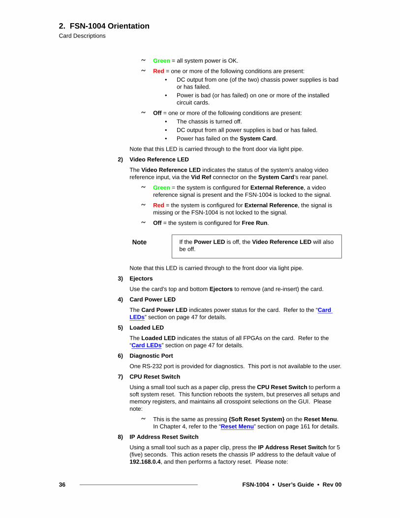
Three connectors are provided for Universal Input 1 (1 x HD15, 1 x DVI-I, 1 x BNC). Using these connectors, different combinations of inputs can be connected to the FSN-1004, as outlined below, but only one of the three connectors can be used at a time in the GUI.
Cells with check marks denote the connections required for the indicated format.
* up to 165 MHz
** NTSC, PAL or HD
*** up to 165 MHz (UXGA)
Please note the following important points regarding the UIC:
~ Refer to the “Analog Format Connection Table” section on page 48 for additional information on using the HD-15 connector.
5) Universal Input 2
Input connections for Universal Input 2 are identical to Universal Input 1. Refer to the explanation of Universal Input 1 for details.
Table 2-2. UIC connector combinations for selected universal input formats
Connectors
Format BNC DVI-I HD-15
3G-SDI
HD-SDI
SD-SDI
DVI *
CVBS
Y/C
YPbPr **
RGsB
RGBS
RGBHV ***
Note In Appendix A, refer to the “Delay Specifications” section on page 226 for details on UIC delay.
42 FSN-1004 • User’s Guide • Rev 00

2. FSN-1004 OrientationCard Descriptions
pí~åÇ~êÇ=lìíéìí=`~êÇ Installed in slots: 12, 13
Number of cards per chassis: 2
The SOC (Standard Output Card) is a two-channel scaler card that creates scaled video and/or computer Aux outputs up to UXGA or 1920 x 1080. Users can set the output resolution to be different from (or the same as) the system’s native resolution.
Use the Aux Setup Menu to map Aux outputs and name Aux outputs (if desired). Refer to the “Card Slot Allocation” section on page 27 for details on SOC configurations in the FSN-1004.
The figure below illustrates the SOC’s front edge and rear panel connectors:
Figure 2-9. SOC front edge and rear panel connectors
Following are descriptions of all SOC components:
1) Ejectors
Use the card’s top and bottom Ejectors to remove (and re-insert) the card.
2) Card Power LED
The Card Power LED indicates power status for the card. Refer to the “Card LEDs” section on page 47 for details.
3) Loaded LED
SD
IA
nalo
gD
VI
Dig
ital
Ana
log
DV
I Dig
ital
2
1
1
1
Front Edge Rear Panel
4
5
32
1) Ejectors 3) Loaded LED 5) Universal Output 2
2) Card Power LED 4) Universal Output 1
FSN-1004 • User’s Guide • Rev 00 43

2. FSN-1004 OrientationCard Descriptions
The Loaded LED indicates the status of all FPGAs on the card. Refer to the “Card LEDs” section on page 47 for details.
4) Universal Output 1
Three connectors are provided for Universal Output 1:
~ 1 x HD15
~ 1 x DVI-I
~ 1 x BNC
Using these connectors, different combinations of outputs can be connected to the FSN-1004, as outlined below.
Cells with check marks denote the connections required for the indicated format.
* up to 165 MHz
** NTSC, PAL or HD
*** up to 165 MHz (UXGA)
Refer to the “Analog Format Connection Table” section on page 48 for additional information on using the HD-15 connector.
5) Universal Output 2
Output connections for Universal Output 2 are identical to Universal Output 1. Refer to the explanation of Universal Output 1 for details.
Note that test patterns can be assigned to any SOC output, and a raster box can be turned on or off. In Chapter 4, see the “Output Test Patterns Menu” section for details.
Note Multiple outputs on a single SOC channel can be active at the same time, provided that the selected format is compatible. For example, 1920 x 1080i @ 59.94 is a compatible format on all three output connectors.
Table 2-3. SOC connector combinations for selected universal output formats
Connectors
Format BNC DVI-I HD-15
3G-SDI
HD-SDI
SD-SDI
DVI *
CVBS
Y/C
YPbPr **
RGsB
RGBS
RGBHV ***
44 FSN-1004 • User’s Guide • Rev 00

2. FSN-1004 OrientationCard Descriptions
jìäíáîáÉïÉê=`~êÇ Installed in slot: 11
The MVR (Multiviewer) provides the ability to display up to 16 source PIPs in both single and dual monitor configurations. With the desired monitor(s) connected to the card, users can set the MVR’s output resolution, and select from a variety of pre-defined multiviewer layouts.
The figure below illustrates the MVR’s front edge and rear panel connectors:
Figure 2-10. MVR front edge and rear panel connectors
Following are descriptions of all MVR components:
1) Ejectors
Use the card’s top and bottom Ejectors to remove (and re-insert) the card.
2) Card Power LED
The Card Power LED indicates power status for the card. Refer to the “Card LEDs” section on page 47 for details.
3) Loaded LED
The Loaded LED indicates the status of all FPGAs on the card. Refer to the “Card LEDs” section on page 47 for details.
SD
ID
VI D
igita
lD
VI D
igita
l
2
1
LTC
In
put
Pow
er
Loa
ded
Mul
tivie
we
r C
ard
MVR
1
1
Front Edge Rear Panel
4
5
32
6
1) Ejectors 3) Loaded LED 5) MVR Output 2
2) Card Power LED 4) MVR Output 1 6) LTC Input
FSN-1004 • User’s Guide • Rev 00 45

2. FSN-1004 OrientationCard Descriptions
4) MVR Output 1
In order to provide multiviewer connections to both SDI and DVI compatible monitors, two connectors are provided for MVR Output 1:
~ 1 x DVI-I
~ 1 x BNC
The same output signal appears on both the DVI-I and BNC connectors. MVR Output 1 can be used in both single and dual multiviewer monitor configurations, as selected on the Multiviewer Setup Menu:
~ In a single monitor layouts, the selected layout appears identically on MVR Output 1 and MVR Output 2.
~ In a dual monitor layouts, one half of the selected layout appears on MVR Output 1, and the other half appears on MVR Output 2.
Please note:
~ The output resolution for both MVR outputs is set on the Multiviewer Output Setup Menu, using the Output Format Keypad.
~ Both the BNC and DVI-I connectors can be active at the same time, provided that the selected format is compatible. The valid combinations are fully listed in the Output Format Keypad.
~ Refer to Chapter 7, “Multiviewer Operations” on page 197 for full multiviewer setup details.
5) MVR Output 2
Output connections for MVR Output 2 are identical to MVR Output 1. See above for details.
6) LTC Input
One Phoenix connector is provided for the Multiviewer’s LTC (Longitudinal Time Code) Input.
Figure 2-11. LTC Input connector
Two types of time code connections are possible:
~ For a differential connection, use the +, – and GND terminals.
~ For a single-ended connection, use the + and GND terminals.
Please note:
• Test patterns can be assigned to any MVR output, and a raster box can be turned on or off. In Chapter 4, see the “Output Test Patterns Menu” section for details.
46 FSN-1004 • User’s Guide • Rev 00

2. FSN-1004 OrientationCard LEDs
`~êÇ=ibaëOn the front edge of all cards, two LEDs indicate the card’s FPGA and power status.
Figure 2-12. Card front edge LEDs
Following are descriptions of the two LEDs:
1) Card Power LED
The Card Power LED indicates power status for the card.
~ Green = card power is OK.
~ Red = power is bad (or has failed) on the card.
~ Off = the chassis is turned off or power has failed.
2) Loaded LED
The Loaded LED indicates the status of all FPGAs on the card.
~ Green = all FPGAs are loaded successfully.
~ Red = an FPGA is malfunctioning, or software has not properly loaded.
~ Off = the chassis is turned off or power has failed.
Note An FPGA (field-programmable gate array) is a semiconductor device that can be reconfigured after manufacturing — hence the name "field-programmable”
1) Card Power LED 2) Loaded LED
Pow
er
Load
ed
1 2
FSN-1004 • User’s Guide • Rev 00 47

2. FSN-1004 OrientationAnalog Format Connection Table
^å~äçÖ=cçêã~í=`çååÉÅíáçå=q~ÄäÉEach HD-15 analog connector on both the UIC and SOC enables you to input (or output) a variety of video formats — including VGA, composite video, S-Video and YUV component video.
• For RGB with H and V sync, use the HD-15 connector directly.
• Using a customer supplied HD-15 to 5 x BNC breakout cable, many combinations are possible. Cells with check marks denote the connections required for the indicated format.
Table 2-1. Analog Input and Output Combinations using Breakout Cable
Breakout Cable Wire Color
Composite Video
S-Video(Y/C)
YUV(YPbPr)
RGBSync on Green
RGBComp Sync
RGBSeparate H V
R (Pr)
G (Lum) (Lum)
B (Chroma) (Pb)
H Sync
V Sync
48 FSN-1004 • User’s Guide • Rev 00

PK==fåëí~ää~íáçå
få=qÜáë=`Ü~éíÉêThis chapter provides detailed instructions for installing FSN-1004 hardware. The following topics are discussed:
• Safety Precautions
• Shipping Information
• Unpacking and Inspection
• Site Preparation
• Cable and Adapter Information
• FSN-1004 Rack-Mount Procedure
• System Connections
• Card and Rear Panel
• Signal Connections
• Analog Format Connection Table
Please note the following important points:
• As you follow the installation instructions in this chapter, remember the following important term:
~ Native Resolution — The resolution to which all processing is set within the switcher frame.
• In Chapter 5, refer to the “Aux Output Setup” section on page 175 for instructions on setting the native resolution.
Note Once you have reviewed all of the sections in this chapter, please continue with Chapter 4, “Menu Orientation” on page 69.
FSN-1004 • User’s Guide • Rev 00 49

3. InstallationSafety Precautions
p~ÑÉíó=mêÉÅ~ìíáçåë=For all FSN-1004 installation procedures, observe the following important safety and handling rules to avoid damage to yourself and the equipment:
• To protect users from electric shock, ensure that the power supplies for each unit connect to earth via the ground wire provided in the AC power cord.
• AC Socket-outlets should be installed near the equipment and be easily accessible.
pÜáééáåÖ=fåÑçêã~íáçåAll FSN-1004 systems are shipped in one box as follows:
• Box 1
~ FSN-1004 chassis and cards
• If a redundant power supply is ordered, it is shipped in its own box.
råé~ÅâáåÖ=~åÇ=fåëéÉÅíáçå=Inspect the shipping boxes for damage. If you find any damage, notify the shipping carrier immediately for all claims adjustments. As you open each box, compare its contents against the packing slips. If you find any shortages, contact your Barco sales representative.
Once you have removed all components from their packaging and checked that the listed components are present, inspect each unit to ensure there was no shipping damage. If there is damage, notify the shipping carrier immediately for all claims adjustments.
páíÉ=mêÉé~ê~íáçå=The environment in which you install your FSN-1004 switcher should be clean, properly lit, free from static, and have adequate power, ventilation, and space for all components.
`~ÄäÉ=~åÇ=^Ç~éíÉê=fåÑçêã~íáçåThe table below provides information regarding cables included with the FSN-1004:
50 FSN-1004 • User’s Guide • Rev 00

3. InstallationCable and Adapter Information
Table 3-1. FSN-1004 Cables
Cable / Adapter Description Quantity
AC Power Cord 7 foot, 10A (US Power Cord) 1
AC Power Cord 7 foot, 10A (European Power Cord) 1
FSN-1004 • User’s Guide • Rev 00 51

3. InstallationPC Connection
m`=`çååÉÅíáçåThe figure below illustrates the connectors and cabling used to connect your Personal Computer (PC) to the FSN-1004.
Figure 3-1. PC Installation
Use the following steps to connect your PC:
1. Using standard Ethernet cables, connect an Ethernet Port on your PC to a customer supplied Ethernet Switch. Then, connect the FSN-1004’s Ethernet Port to the Ethernet Switch.
AC Power
Ethernet
Ethernet Switch (customer-supplied)
Your PC
FSN-1004
Ethernet
AC Power
Note Although the use of the Switch is recommended, you can use a direct Ethernet connection between the FSN-1004 and your PC as an alternate method.
52 FSN-1004 • User’s Guide • Rev 00

3. InstallationFSN-1004 Rack-Mount Procedure
cpkJNMMQ=o~ÅâJjçìåí=mêçÅÉÇìêÉThe FSN-1004 chassis is designed to be rack mounted and is supplied with front rack-mount hardware. Please note the following important points:
• The FSN-1004 is 6RU in height.
• When rack mounting the unit, remember that the maximum ambient operating temperature is 40 degrees C.
• Leave sufficient front and rear space to ensure that airflow through the FSN-1004 is not restricted.
• When installing equipment into a rack, distribute the units evenly to prevent hazardous conditions that may be created by uneven weight distribution.
• Connect the FSN-1004 only to a properly rated supply circuit.
• Reliable grounding (earthing) of rack-mounted equipment should be maintained.
• Rack mount the FSN-1004 from the front rack ears using four rack screws (not supplied). Threads may be metric or otherwise, depending upon the rack type.
Use the following steps to rack mount the FSN-1004:
1. An FSN-1004 chassis weighs 77 pounds (34.92 kg). To avoid injury, it is recommended that two people rack mount the chassis.
2. The FSN-1004 ships with side rails installed, which when properly adjusted, assist with the distribution of chassis (and cable) weight within your rack. Use the following steps to properly adjust the side rails:
a. Measure and install the two supplied mounting brackets on your rear rack rails.
Figure 3-2. Rear rail mounting bracket
b. Measure the distance between the front and rear rack rails. Remove the four mounting screws that secure each side rail to the FSN-1004, then adjust the spacing of each side rail as necessary.
Figure 3-3. Side rail adjustment
c. Re-install the mounting screws. When properly adjusted, the end of each side rail will protrude through the slot in the rear mounting bracket, once the chassis is rack mounted.
Chassis rear
Side rail
Mounting screws
FSN-1004 • User’s Guide • Rev 00 53

3. InstallationFSN-1004 Rack-Mount Procedure
3. To facilitate easy rack mounting, each rack ear on the front of the FSN-1004 is equipped with a special “keyhole” slot on the lower hole, as shown below.
Figure 3-4. Rack Ear Keyhole
To take advantage of this feature, ensure that there is at least 1/2” of clearance above the chassis’ intended 6RU location.
Figure 3-5. Equipment Rack Layout
4. For the FSN-1004’s two keyhole slots, measure and install two rack screws in your equipment rack’s front rails. Allow each screw to protrude approximately 3/4” from the surface of the rails.
5. Lift the chassis, and while supporting it, slide the side rails through the slots in the rear mounting brackets.
6. While continuing to support the chassis, slide the screws (in the front rails) through the two keyholes, and let the chassis settle up into the keyhole slots.
7. Tighten the two lower screws, then install and tighten the two uppers screws in the rack rail.
6RU
.5" Additional Clearance
54 FSN-1004 • User’s Guide • Rev 00

3. InstallationSystem Connections
póëíÉã=`çååÉÅíáçåëThe figure below illustrates the connections on the System card’s rear panel, plus the power connections. Use this figure for reference during installation.
Figure 3-6. System card and power connections
Use the following steps to install “system” connections on the FSN-1004:
1. Ensure that the FSN-1004 is properly rack mounted. If not, refer to the “FSN-1004 Rack-Mount Procedure” section on page 53 for instructions.
2. On the System card’s rear panel, ensure that the Ethernet Port is connected to the Ethernet Switch, and the Switch is connected to an Ethernet Port on your PC.
AC
AC
ReferenceVideo In
ReferenceVideo Loop Out
Toan Ethernet Port
on your PC
12 13 14
Ref In
Loop
Ethernet
100 - 240 VAC8A, 50 - 60 Hz x2
2
1
Note As an alternate method, you can use a direct Ethernet connection between the FSN-1004 and your PC.
FSN-1004 • User’s Guide • Rev 00 55

3. InstallationSystem Connections
3. (Recommended) Using a BNC cable, connect an analog reference video input to the Ref In connector. This connection enables you to genlock the FSN-1004 to an external reference.
~ Accepted signals are black burst, SMPTE bi-level sync and tri-level sync.
~ Computer sync is not an accepted signal.
4. (Optional) Using a BNC cable, connect the Loop connector to the reference video input on the next device in your video system. This connection enables you to “daisy-chain” reference video to additional devices.
5. (Optional) Using a BNC cable, connect the Ref Out connector to the reference video input connector on the next video device in your system, or to a reference DA (distribution amplifier) for multiple reference feeds.
Please note:
~ Using the {Reference Out} button on the Reference and Output Setup Menu, toggle this output between Tri-Level Sync and Black Burst.
~ The sync out format (as provided on the connector) changes, depending on the selected native video format. In Appendix A, refer to the “Reference Video Output Specifications” section on page 223.
6. For AC connections, one AC connector is provided for each FSN-1004 power supply. Please note:
~ One supply is standard, the redundant supply is optional.
~ In a redundant configuration with both supplies installed, the FSN-1004 can be powered from two different circuit breakers.
Open the FSN-1004 front door and note the number of power supplies installed. If only one supply is installed, note its location (in the top or bottom slot).
Important If the reference Loop connection is not used, connect a 75 ohm terminator to the connector.
Important This connection assumes that the FSN-1004 is the “master” sync source in your system, for distributing an advanced sync signal to additional devices such as cameras.
56 FSN-1004 • User’s Guide • Rev 00

3. InstallationSystem Connections
7. Connect the supplied AC Power Cord(s) to the AC connectors on the rear of the FSN-1004, and then to AC outlet(s).
~ If a power supply is installed in the top slot, use AC Connector 1.
~ If a power supply is installed in the bottom slot, use AC Connector 2.
Note Connect the FSN-1004 to a properly rated supply circuit. Reliable grounding of rack-mounted equipment should be maintained. Refer to the “Power Cord/Line Voltage Selection” section on page 58 for details.
FSN-1004 • User’s Guide • Rev 00 57

3. InstallationSystem Connections
mçïÉê=`çêÇLiáåÉ=sçäí~ÖÉ=pÉäÉÅíáçåThe FSN-1004 is rated to operate with the following specifications:
• Input Power: 100-240 VAC, 50-60 Hz
• Power Consumption: 800 watts maximum
Each FSN-1004 component performs line voltage selection automatically, and no user controls are required. The AC power cords must be accessible so that they can be removed during field servicing.
Figure 3-7. Tandem Prong-type Plug
Warning When the FSN-1004 is used in the 230-volt mode, a UL listed line cord rated for 250 volts at 15 amps must be used and must conform to IEC-227 and IEC-245 standards. This cord will be fitted with a tandem prong-type plug.
The rear panel ON/OFF switch does not disconnect the unit from input AC power. To facilitate disconnection of AC power, the power cord must be connected to an accessible outlet near the unit.
Building Branch Circuit Protection (minimum requirements): For 115 V use 20 A, for 230 V use 8 A.
Avertissement La choix de la ligne de voltage se réalise automatiquement par le FSN-1004 Transformateur Graphique. On n'a pas besoin du controller usager pour la choix de la ligne de voltage.
Warnung Das FSN-1004 gerät mu beim Anschlu an 240V ~ mit einer vom VDE auf 250V/10A geprüften Netzleitung mit einem Schukostecker ausgestattet sein.
58 FSN-1004 • User’s Guide • Rev 00

3. InstallationCard and Rear Panel
`~êÇ=~åÇ=oÉ~ê=m~åÉäThe FSN-1004 ships with all cards installed. The following instructions are provided in case a card needs to be replaced.
The table below outlines the card slots within the FSN-1004 chassis. Use this chart for reference during the following procedures, and remember that all cards and their rear panels are hot-swappable.
Use the procedures in the following sections to insert (and extract) cards, as required:
• Rear Panel Insertion
• Rear Panel Removal
• Card Insertion
• Card Removal
Table 3-2. FSN-1004 chassis card slot allocations
Card Type Max. # of Cards per Chassis Slot Number(s)
System 1 14
M/E 1 8
UIC (Universal Input Card), 2-channel 5 3 - 7
MVR (Multiviewer Card) 1 11
SOC (Standard Output Card), 2-channel 3 12, 13
FSN-1004 • User’s Guide • Rev 00 59

3. InstallationCard and Rear Panel
oÉ~ê=m~åÉä=fåëÉêíáçå To insert a rear panel:
1. Use Table 3-2 on page 59 to verify the slots in which the cards and their corresponding rear panels can be installed. Front and rear slot numbers will match. For example, if you install an SOC in front slot 13, its corresponding rear panel must be installed in rear slot 13.
2. If a blank rear panel is installed in the target slot, loosen the two captive thumb screws in the blank panel, remove it, and store it safely.
3. Ensure that the selected rear panel is properly oriented:
~ UIC: orient the label “1” at the top.
~ SOC: orient the label “1” at the top.
~ MVR: orient the label “1” at the top.
4. Using the nylon guides in the chassis for alignment, carefully insert the rear panel into the chassis. Be sure to push on both the top and bottom thumb screws simultaneously, until the card is fully seated in the chassis connector.
5. Once the panel is fully seated, tighten the two thumb screws.
6. Repeat from step 1 for all additional rear panels that you want to install.
oÉ~ê=m~åÉä=oÉãçî~ä To remove a rear panel:
1. Loosen the two captive thumb screws in the rear panel, and carefully remove it from the FSN-1004 chassis. Store the panel safely for later use.
2. Install a blank panel in its place.
3. Repeat from step 1 for all additional rear panels that you want to remove.
Caution Always push both thumb screws simultaneously. If you only push on one, you can damage the panel or bend a pin.
Important Unused rear slots must always have blank panels installed.
60 FSN-1004 • User’s Guide • Rev 00

3. InstallationCard and Rear Panel
`~êÇ=fåëÉêíáçå To insert a card:
1. Use Table 3-2 on page 59 to verify the slots in which the card can be installed.
2. Once verified, open the chassis front door and remove it (if desired). In Chapter 2, refer to the “Chassis Front Door” section on page 28 for details.
3. Orient the card so that the label (e.g., UIC) is at the top. Ensure that both ejectors are unlatched from the slots in the card’s front plate.
4. Once unlatched, hold the top ejector up, as shown below. The bottom ejector will automatically fall away from the front of the card.
Figure 3-8. Ejector Orientation prior to card insertion
Hold up
Bottom Ejector
Card
top Ejector
FSN-1004 • User’s Guide • Rev 00 61

3. InstallationCard and Rear Panel
5. Using the nylon guides in the chassis for alignment, carefully insert the card into the chassis until both ejectors engage the rim of the card cage. Each ejector will “automatically” angle towards the middle of the card.
Figure 3-9. Ejectors engaged in card cage rim
6. On each ejector, squeeze the two black handles together, then simultaneously push both latches into the slot on the card’s front plate — until the card is fully seated in the FSN-1004 chassis.
Figure 3-10. Final card insertion
Card
Card Cage Rim
Squeezetogether
Squeezetogether
Push, latch and release
Push, latch and release
Caution Always push both latches simultaneously. If you only use one latch, you can damage the card.
62 FSN-1004 • User’s Guide • Rev 00

3. InstallationCard and Rear Panel
7. Release the handles so that they spring back and lock into place.
8. Repeat from step 1 for all additional cards that you want to install.
9. When complete, re-install the chassis front door, close and secure.
`~êÇ=oÉãçî~ä To remove a card:
1. Open the chassis front door and remove it (if desired).
2. For the selected card, simultaneously squeeze the two black handles together on each ejector, then pull the ejectors away from the center of the card.
Figure 3-11. Card removal
3. When both latches have disengaged from the chassis, remove the card completely and store it safely in an anti-static bag.
4. Repeat from step 2 for all additional cards that you want to remove.
5. When complete, re-install the chassis front door (if required), close and secure.
Squeezetogetherand pull
Squeezetogetherand pull
Caution Always pull both latches simultaneously. If you only use one latch, you can damage the card.
Important Unused rear slots must always have blank panels installed.
FSN-1004 • User’s Guide • Rev 00 63

3. InstallationSignal Connections
páÖå~ä=`çååÉÅíáçåëThe following topics are discussed in this section:
• Output Connections
• Universal Input Connections
• Analog Format Connection Table
• Multiviewer Connections
64 FSN-1004 • User’s Guide • Rev 00

3. InstallationSignal Connections
lìíéìí=`çååÉÅíáçåëAux (auxiliary) buses are extra switching buses that allow video signals to be routed from the FSN-1004 to external equipment. The figure below illustrates the Aux output connections on the M/E card’s rear panel, and the SOC rear panel:
Figure 3-12. Aux output connections
Use the following steps to connect Aux outputs from the FSN-1004.
1. Using BNC cables, connect Aux Outputs 1 through 6 to your target auxiliary devices or monitors. These six outputs run at the system’s native resolution.
2. Use BNC, DVI or HD-15 cables (as required) to connect outputs to your target devices. Use the Aux Setup Menu to set the output resolution for each SOC output. In Chapter 4, refer to the “Output Setup Menu” section for setup details.
Please note:
• Use the Aux Setup Menu to map SOC Aux outputs to a GUI button, and name Aux outputs (if desired). In Chapter 4, refer to the “Output Setup Menu” section on page 138 for setup details.
Aux Out 1
Aux Out 2
Aux Out 3
Aux Out 4
Aux Out 5
Aux Out 6
SD
IA
nalo
gD
VI D
igita
lA
nalo
gD
VI D
igita
l
2
1
Note:Use the
Aux Setup Menuto map
all SOC outputs and set the
output resolution
FSN-1004 • User’s Guide • Rev 00 65
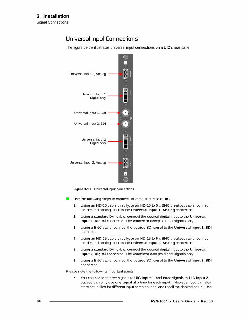
3. InstallationSignal Connections
råáîÉêë~ä=fåéìí=`çååÉÅíáçåëThe figure below illustrates universal input connections on a UIC’s rear panel:
Figure 3-13. Universal input connections
Use the following steps to connect universal inputs to a UIC.
1. Using an HD-15 cable directly, or an HD-15 to 5 x BNC breakout cable, connect the desired analog input to the Universal Input 1, Analog connector.
2. Using a standard DVI cable, connect the desired digital input to the Universal Input 1, Digital connector. The connector accepts digital signals only.
3. Using a BNC cable, connect the desired SDI signal to the Universal Input 1, SDI connector.
4. Using an HD-15 cable directly, or an HD-15 to 5 x BNC breakout cable, connect the desired analog input to the Universal Input 2, Analog connector.
5. Using a standard DVI cable, connect the desired digital input to the Universal Input 2, Digital connector. The connector accepts digital signals only.
6. Using a BNC cable, connect the desired SDI signal to the Universal Input 2, SDI connector.
Please note the following important points:
• You can connect three signals to UIC Input 1, and three signals to UIC Input 2, but you can only use one signal at a time for each input. However, you can also store setup files for different input combinations, and recall the desired setup. Use
Universal Input 1, Analog
Universal Input 1
Universal Input 1, SDI
SD
IA
nalo
gD
VI D
igita
lA
nalo
gD
VI D
igita
l
2
1
Universal Input 2, SDI
Universal Input 2
Universal Input 2, Analog
Digital only
Digital only
66 FSN-1004 • User’s Guide • Rev 00

3. InstallationSignal Connections
the Input Setup Menu to set up universal input signals. In Chapter 4, refer to the “Input Setup” section on page 117 for setup details.
• In Chapter 5, refer to the “Universal Input Setup” section on page 172 for step-by-step setup instructions.
• Refer to the “Analog Format Connection Table” section on page 67 for a chart of analog formats available when using a customer supplied breakout cable.
• In Appendix A, refer to the “Output Format Tables” section on page 231 for a list of available input formats for the FSN-1004.
• The two SDI inputs enable you to connect SDI sources.
^å~äçÖ=cçêã~í=`çååÉÅíáçå=q~ÄäÉEach HD-15 analog connector on the UIC enables you to input a variety of video formats — including VGA, composite video, S-video and YUV component video.
• For RGB with H and V sync, use the HD-15 connector directly.
• Using a customer supplied HD-15 to 5 x BNC breakout cable, several input combinations are possible. Cells with check marks denote the connections required for the indicated format.
Table 3-1. Analog Input Combinations using Breakout Cable
Breakout Cable Wire Color
Composite Video
S-Video(Y/C)
YUV(YPbPr)
RGBSync on Green
RGBComp Sync
RGBSeparate H V
R (Pr)
G (Lum) (Lum)
B (Chroma) (Pb)
H Sync
V Sync
FSN-1004 • User’s Guide • Rev 00 67

3. InstallationSignal Connections
jìäíáîáÉïÉê=`çååÉÅíáçåëThe figure below illustrates monitor output connections on the MVR’s rear panel:
Figure 3-14. Universal input connections
Please note:
• In both single and dual monitor configurations (as selected on the Multiviewer Setup Menu), the same signal appears on both the DVI-I and BNC connectors.
Use the following steps to connect MVR outputs to your monitor(s).
1. In single monitor configurations, use DVI and/or BNC cables to connect the DVI and/or SDI multiviewer output(s) to your monitor(s). The same signal appears on outputs 1 and 2.
2. In dual monitor configurations:
~ Use DVI and/or BNC cables to connect the DVI and/or SDI multiviewer Monitor 1 output(s) to your assigned “left” monitor(s).
~ Use DVI and/or BNC cables to connect the DVI and/or SDI multiviewer Monitor 2 output(s) to your assigned “right” monitor(s).
3. If you want to display time on the Multiviewer from an external LTC source, connect the output of your time code source (e.g., time code generator) to the LTC Input as follows:
~ For a differential connection, use the +, – and GND terminals.
~ For a single-ended connection, use the + and GND terminals.
Multiviewer Output 1, DVI
Multiviewer Output 1, SDI
Multiviewer Output 2, SDI
Multiviewer Output 2, DVI
LTC Input
(Digital only)
(Digital only)
SD
ID
VI D
igita
lD
VI D
igita
l
2
1
LTC
Inp
ut
68 FSN-1004 • User’s Guide • Rev 00

QK==jÉåì=lêáÉåí~íáçå
få=qÜáë=`Ü~éíÉêThis chapter describes all system menus, including the functions that are available, and descriptions of each menu tree (in block diagram format).
The following topics are discussed:
• Menu Tree
• Using the Menu System
• Buttons, Tables and Matrices
• Using the Keypad
• Using the Pop-up Keyboard
• Memory Menu
• Stills Menu
• Screens Menu
• System Menu
Note Once you have reviewed all of the sections in this chapter, please continue with Chapter 5, “System Setup” on page 163.
FSN-1004 • User’s Guide • Rev 00 69

4. Menu OrientationMenu Tree
jÉåì=qêÉÉTwo menu trees are illustrated in this section. Please use these diagrams for reference as you learn how to operate the system.
• High-Level Menu Tree
• System Menu Tree
eáÖÜJiÉîÉä=jÉåì=qêÉÉThe figure below illustrates a high-level view of the menu tree.
Figure 4-1. FSN-1004 High-Level Menu Tree
MenuEntry
Com Setup
Out Test Patterns
Input Setup
User Prefs
Save All
Software
Reset
Backup/Restore
Lock GUI
MVR Setup
Output Setup
Memory
Store
Enables
Advanced
Description
Registers
System
Buffer Matrix
Stills
Memory Table
Recall
System Table
Match PGM
Screens
Mem Store
Aux Table
Capture
Assign Source
Capture Still
Auto-Advance
Delete All
Erase All
Recall
Name Source
Delete Store
See NextFigure For
Details
Mem Recall
Auto Trans
Recall Prev
Unselect All
Cut
Trans Rate
Recall Next
Select All
70 FSN-1004 • User’s Guide • Rev 00

4. Menu OrientationMenu Tree
póëíÉã=jÉåì=qêÉÉThe figure below illustrates an expanded view of the System Menu.
Figure 4-2. FSN-1004 System Menu Tree
Com Setup
Out Test PatternsInput Setup
User Prefs
Save All
Software
Reset
Backup/Restore
Lock GUI
Discover FSN
Set IP
Set Subnet
Apply
Restore Defaults
Ethernet Table
Input Table
Input Name
Freeze
Error Reporting
Freeze
Info
Setup
UniversalInput Setup
Input Table
Save Settings
Restore Saved
Restore Default
Sizing and Scaling
Size & Position
Pan Zoom Src
Mask
ColorCorrection
Bright/Contr/Gam
RGB Bright
RGB Contrast
Hue Sat
Prefs Table
Set
Reset to Default
Status Table
Output View
Select All Outs
Pattern Matrix
Off
Raster Box
All Off
Backup Sys
Restore Sys
Factory Reset
Reset to Defaults
MVR Setup
Output Setup
Select Layout
Select Colors
Clock Setup
Mode
Assign Source
UMD Text
UMD Color
Output Setup
Out Name
M/E Format/Rate
M/E Out Type
Unassign Aux
Setup
Set Clock
Capture and Process
Auto Acquire
Input Format
EDID Format
Color Space
1:1 Sampling
Sample Phase
Adj H Timing
Adj V Timing
Sharpness
Pulldown Comp
System
System Table
FSN-1004 • User’s Guide • Rev 00 71

4. Menu OrientationUsing the Menu System
rëáåÖ=íÜÉ=jÉåì=póëíÉãThis section lists the rules and conventions for using FSN-1004 menus. For orientation purposes only, the figure below illustrates the various menu sections.
Figure 4-3. Sample Menu Layout
Following are descriptions of each section and each type of button:
1) Title Bar
At the top of each menu, the Title Bar always names the current menu. When sub-menus are displayed, the convention of “Parent Menu > Sub Menu” will be used, e.g., Keyer Menu > Advanced.
2) Prompt Bar
Immediately below the Title Bar, the Prompt Bar provides a line of “help text” for each menu. The prompt changes according to the various functions selected on the menu.
1 2
4
5
3
1) Title Bar 3) Palette 5) Tool Bar
2) Prompt Bar 4) Menu Bar
72 FSN-1004 • User’s Guide • Rev 00

4. Menu OrientationUsing the Menu System
3) Palette
In the center of the menu, the Palette provides an area for menu-specific and function-specific buttons, graphics and tables.
4) Menu Bar
Along the left side, the Menu Bar provides instant access to all primary menus. Each button is latching, and mutually exclusive with all other navigation buttons. When pressed, the button “lights” and the selected menu is displayed.
Figure 4-4. Navigation button selection
The Menu Bar does not scroll. Instead, press the Page button at the bottom of the bar to change navigation pages in groups of six buttons with each press.
5) Tool Bar
The Tool Bar at bottom edge of the menu displays up to 10 primary functions and options for the selected menu.
Keys Keys
Unselected Selected
Note There are many types of buttons that can appear on the Tool Bar and in the Palette. Refer to the “Buttons, Tables and Matrices” section on page 74 for details.
FSN-1004 • User’s Guide • Rev 00 73

4. Menu OrientationButtons, Tables and Matrices
_ìííçåëI=q~ÄäÉë=~åÇ=j~íêáÅÉëThere are a variety of button “types” that can appear in the menus, and there are also general rules that apply to button categories, colors, tables and matrices. Detailed explanations are provided below.
• Button Categories and Colors
• Latching, Momentary and Conditional Buttons
• Value Buttons
• Toggle Buttons
• Pop-up Buttons
• Location Buttons
• Summary of Button Types
• Tables
• Matrices
• Notes and Error Messages
_ìííçå=`~íÉÖçêáÉë=~åÇ=`çäçêëGeneral button categories and color schemes are outlined below:
• Menu Bar Buttons are always gray. When pressed, the button lights and the selected menu is displayed in the Palette.
Figure 4-5. Menu Bar Buttons
• Function Buttons are always blue, and there are many different types such as “pop-ups” and “toggles.” Each type performs a specific function on the current menu, and behaves in a specific manner. See below for details.
Figure 4-6. Function Buttons
Note that in some cases, a button may be “grayed out,” indicating that the function is currently not available.
Figure 4-7. Grayed Out Button
Menu
Function
GrayedOut
74 FSN-1004 • User’s Guide • Rev 00

4. Menu OrientationButtons, Tables and Matrices
• Navigation Buttons are brown, and when pressed, they take you to a new location in the menu tree. For example:
~ Press to switch to a sub-menu beneath the current “parent” menu. In the sub-menu, the {Back} button appears in the Tool Bar, enabling you to go “back” up one level in the menu tree.
~ Press to switch to a completely different menu, or a special navigation pop-up, that enables you to choose the next destination menu.
Figure 4-8. Navigation Buttons
i~íÅÜáåÖI=jçãÉåí~êó=~åÇ=`çåÇáíáçå~ä=_ìííçåëLatching, momentary and conditional buttons are explained below:
• Latching
The figure below illustrates both states of a Latching function button. The name of the function is written on the button itself.
Figure 4-9. Latching button states
~ When OFF, the button is unselected, unlit, and the function is inactive.
~ When ON, the button is selected, lit, and the function is active.
• Momentary
Both “function” and “navigation” buttons can be momentary:
~ A Momentary blue “function” button lights briefly when pressed, performs the selected function, then returns to its default “off” condition.
Figure 4-10. Momentary Function Button Sequence
Navigation NavigationNewMenu
Note Because its function remains constant throughout the entire menu system, the {Back} button will not be explained any further in this chapter.
Function Function
Unselected Selected
Function Function Function
FSN-1004 • User’s Guide • Rev 00 75

4. Menu OrientationButtons, Tables and Matrices
• Conditional
The figure below illustrates both states of a Conditional function button.
Figure 4-11. Conditional button states
Conditional buttons appear when certain conditional functions are required. They can be either momentary or latching, depending on the required function.
s~äìÉ=_ìííçåëThe figure below illustrates a Value button.
Figure 4-12. Value button
When certain functions are enabled in a menu. These buttons let you to enter values for the selected parameter. The parameter’s current value appears within the button’s dark blue insert. To adjust the value:
• Press the value button. When pressed, the button latches and the Keypad appears. Refer to the “Using the Keypad” section on page 82 for details.
qçÖÖäÉ=_ìííçåëThe figure below illustrates both states of a Toggle button.
Figure 4-13. Toggle button states
Toggle buttons are two-state “function” buttons with a cyan colored insert, and the current state appears within the insert (e.g., On or Off). Pressing the button changes the state of the selected function.
Function Function
ConditionalFunction
Function Off Function On
Function
State 1
Function
State 2
76 FSN-1004 • User’s Guide • Rev 00

4. Menu OrientationButtons, Tables and Matrices
mçéJìé=_ìííçåëThe figure below illustrates both states of a Pop-up button.
Figure 4-14. Pop-up button states (sample)
A Pop-up button has a dark blue colored insert, and just like a Toggle, the current selection appears within the insert. When pressed, the button latches, and a pop-up appears (on top of the Palette) with an array of options.
When you select an option, the pop-up clears and the selection appears within the insert. To cancel without making a change, simply press the pop-up button again to cancel the operation.
içÅ~íáçå=_ìííçåëThe figure below illustrates a Location button.
Figure 4-15. Location button
A Location button is a type of Navigation button that takes you to a new location in the menu tree, but because the button behaves like a pop-up, there is a choice of locations within the same “parent” menu.
When pressed, the button latches, and a pop-up appears. When you select a location, the pop-up clears and the new location appears within the yellow insert.
To cancel without making a change, simply press the pop-up button again to cancel the operation.
Option1
Option2
Option3
Function
Selection
Function
Selection
Location
Location 1
FSN-1004 • User’s Guide • Rev 00 77

4. Menu OrientationButtons, Tables and Matrices
When the switcher location changes, the label in the Title Bar also changes.
The figure below illustrates both states of a Location button.
Figure 4-16. Location button states (sample)
Location
Location 1
Location
Location 1
Location1
Location2
Location3
78 FSN-1004 • User’s Guide • Rev 00

4. Menu OrientationButtons, Tables and Matrices
pìãã~êó=çÑ=_ìííçå=qóéÉëThe table below summarizes buttons types, attributes, colors and functions.
Table 4-1. Button types, colors and functions
Type Attributes Color Insert Function
Menu Bar Latching Gray — Provides direct access to all primary menus.
Function Latching Blue — Enables and disables the selected function. May have an associated “Conditional” button that appears when the function button is latched.
Function Momentary Blue — Performs the selected function, then returns to its default “off” state.
Navigation Momentary Brown — Changes your view to a new location in the menu tree.
Value Latching Blue Dark Blue Enables entry of values for the selected parameter.
Toggle Momentary Blue Cyan Toggles between two states only, for the selected function.
Pop-up Latching Blue Dark Blue Provides a choice of two or more options for the selected function.
Location Latching Brown Yellow Provides a choice of locations within the same “parent” menu.
Menu
Function
Function
Navigation
Function
State 1
Function
Selection
Location
Location 1
FSN-1004 • User’s Guide • Rev 00 79

4. Menu OrientationButtons, Tables and Matrices
q~ÄäÉëThe FSN-1004 user interface makes extensive use of tables, for a variety of functions such as keys, memory registers, tallies, etc. The figure below illustrates a sample table:
Figure 4-17. Sample Table
Each table includes a heading row at the top, and multiple data rows beneath. The “highlighted” yellow row indicates that functions can be performed to the device (or parameter) that is shown on this row.
The yellow highlight can be scrolled automatically or manually. For example:
• On the Input Setup Menu, the highlight automatically jumps to a certain row, when you click on the associated graphic of a rear-panel connector.
• On the Memory Menu, you can simply click on the desired register to highlight the desired row.
Figure 4-18. Manual table, with scrolling via direct touching
Heading
Data
Data
Data
Data
Heading
Data
Data
Data
Data
Heading
Data
Data
Data
Data
Heading
Data
Data
Data
Data
Heading
Data
Data
Data
80 FSN-1004 • User’s Guide • Rev 00

4. Menu OrientationButtons, Tables and Matrices
j~íêáÅÉëOn certain menus such as the Output Test Pattern Menu, matrices are provided that enable you to choose a particular item (from a large group of items). A sample matrix is shown below:
Figure 4-19. Sample Matrix
In the matrix, each function is a mutually exclusive button. To select a function, touch the desired button. The yellow border indicates the current selection. Note that in some cases (as shown above), a function may be grayed out.
kçíÉë=~åÇ=bêêçê=jÉëë~ÖÉëIn certain cases, notes will pop-up that provide important information about a process, a function, or a “prompt” for further action. Each note has a title box, a subject line, an “explanation” section and a Close button — which clears the note from the menu. Some notes also include buttons for various choices, such as “Yes” or “No.”
A sample note is shown below.
Figure 4-20. Sample note
If an error occurs, a red “Error” button will appear in the top right corner of the menu — superimposed over the Title Bar. If this occurs, press the Error button to display a note for more information. A sample error message is shown below.
Figure 4-21. Sample error message
If an “LOS” or “Invalid Signal” error occurs to an input, the Programmable Display turns red, and the red “Error” button appears. These error messages can be turned off, if desired. In Chapter 6, refer to the “Understanding Error Messages” section on page 186 for full details.
Choice 3Choice 1 Choice 2 Choice 4
Choice 7Choice 5 Choice 6 Choice 8
Note SubjectNote
Detailed explanation or “prompt”
Close
Menu Title
Menu Prompt
Error
BriefDetails
FSN-1004 • User’s Guide • Rev 00 81

4. Menu OrientationUsing the Keypad
rëáåÖ=íÜÉ=hÉóé~ÇWhen a value button is pressed, the Keypad appears. The figure below illustrates a sample Keypad:
Figure 4-22. Keypad (sample)
Following are descriptions of each section and each type of button in the Keypad:
1) Function Bar
The Function Bar displays the selected parameter’s range, and when required, provides a mini-prompt for the function that you are entering. For example:
If you press the {Hue} value button, the prompt reads:
Range: 0 - 360
If you press the {Brightness} value button, the prompt reads:
Range: 1 - 100
2) Register
The Register displays a parameter’s current value when the Keypad first appears. This enables you to “trim” existing values or enter new values. The
1) Function Bar 5) +/- 9) Trim -
2) Register 6) Close 10) Trim +
3) Backspace 7) Undo 11) Enter
4) Numerics 8) Clear 12) Decimal
7 8 9
4 5 6 Trim -
1
0
135
Range 0 to 360
2 3
.
+ / - Enter
Undo
Clear
Trim +
Close1 6
7
8
9
10
11
4
5
2
3
12
82 FSN-1004 • User’s Guide • Rev 00

4. Menu OrientationUsing the Keypad
register clears when you begin entering numbers, and digits shift left as you enter them. You must press {Enter} to complete an entry.
3) Backspace
Press Backspace {} during a numeric entry process to clear the register by one digit with each press.
4) Numerics
Press the numeric buttons {0 - 9} to enter values. Digits shift left in the Register as you enter them. Use the {Decimal} button as required for entries that include decimal values.
5) +/-
Press {+/-} to invert the numeric entry in the Register (if applicable). For example, press {+/-} to change +350 to -350.
6) Close
Press {Close} to clear the Keypad from the Touch Screen, and “un-latch” the selected value button.
7) Undo
Prior to pressing {Enter}, press {Undo} at any point during the numeric entry process to restore the original value, even if {Clear} or {+/-} was pressed.
8) Clear
Press {Clear} during a numeric entry process to clear the register to 0 (zero).
9) Trim -
Enter an offset value using the numeric buttons, then press {Trim -} to subtract from the parameter’s current value. Pressing {Enter} is not required, and the “trim” value remains in the register, enabling you to trim repeatedly by the same offset. Once the value is trimmed, you can close the Keypad, or perform addition trims or entries in the normal way.
For example:
To subtract 5 frames from a transition rate, press the Rate button for the desired M/E, then in the Keypad, press {5, Trim -}.
To subtract 25 pixels from a mask value, press the desired mask edge (e.g., {Mask Top}), then in the Keypad, press {25, Trim -}.
Note The {+/-} button is only applicable when certain Keypad functions that accept negative values are active.
Note If you press {Close} prior to pressing {Enter}, {Trim +} or {Trim -}, the Keypad clears, and the previous value is maintained.
Note If {Enter} is pressed, that value becomes the new value to which the register will return, if {Undo} is pressed.
FSN-1004 • User’s Guide • Rev 00 83

4. Menu OrientationUsing the Keypad
10) Trim +
Enter an offset value using the numeric buttons, then press {Trim +} to add to the parameter’s current value. Pressing {Enter} is not required, and the “trim” value remains in the register, enabling you to trim repeatedly by the same offset. Once the value is trimmed, you can close the Keypad, or perform addition trims or entries in the normal way.
For example:
To add 10 frames to a transition rate, press the Rate button for the desired M/E, then in the Keypad, press {1, 0, Trim +}.
To add 2 pixels to a mask value, press the desired mask edge (e.g., {Mask Bottom}), then in the Keypad, press {2, Trim +}.
11) Enter
Press {Enter} to accept a new value. When pressed, the Keypad remains open, and the new value is immediately active.
12) Decimal
Press the decimal button {.} as required for numeric entries that accept decimal values.
Please note the following important points regarding the Keypad:
• Certain Keypad buttons may be grayed out, if their function is not applicable for the current operation.
• On several Keypads throughout the system, a “Default Value” button appears. When pressed, the parameter’s values are returned to their defaults, and the Keypad remains open.
• Other types of Keypads are used in various system modes, to present arrays of functions from which to select, and to present lists from which you can select various items. For example:
When selecting output formats on the Output Setup Menu, a special “list” Keypad enables you to select the desired output format from a list of all available output formats.
When mapping sources to buttons, using the Map Buttons Menu, a special “list” Keypad enables you to select the source that you want to map to the selected GUI button.
Each of these “special” Keypads will be discussed in context with their respective features.
Note The decimal button is only applicable when certain Keypad functions that accept decimal values are active.
84 FSN-1004 • User’s Guide • Rev 00

4. Menu OrientationUsing the Pop-up Keyboard
rëáåÖ=íÜÉ=mçéJìé=hÉóÄç~êÇIn several switcher menus, you can use a pop-up Keyboard to enter names and descriptions for various switcher functions. For example:
On the Input Setup Menu, the Keyboard is used to name inputs, as they’ll appear on the programmable displays.
On the Memory Menu, the Keyboard is used to enter brief descriptions of memory registers.
The figure below illustrates a sample Keyboard, in “name” entry mode:
Figure 4-23. Keyboard (sample)
Please note:
• The top bar provides a prompt for the current action, e.g., entering a name or entering a description.
• Below the prompt is the entry register, where letters appear as you type.
• To use the keyboard, enter the desired text in the normal manner.
~ Press {Enter} to complete an entry and close the Keyboard.
~ Press {Clear Text} to clear the entry register.
~ Press {Cancel} to cancel an entry and close the Keyboard.
• Press {Caps Lock} to switch between upper and lower case, where applicable.
1 2 3 4 5 6 7 8 9 0 - =
Q W E R T Y U I O P
A S D F G H J K L : + EnterCaps Lock
Z X C V B N M /
SpaceCancel Cancel
CAM1
Name for input 3. 4 characters max
ClearText
Note In the Memory Menu (in Store Mode), the new entry will not immediately appear in the register table. Refer to the “Naming Registers” section on page 95 for details.
Note In some modes, such as input name entry, {Caps Lock} remains on, and not all letters and symbols are available.
FSN-1004 • User’s Guide • Rev 00 85

4. Menu OrientationMemory Menu
jÉãçêó=jÉåìThe Memory Menu enables you to manage your memory registers. This includes the ability to view, name, lock and delete registers, plus the ability to enable or disable Memory Modules, and the sub-sections within each module called “Enables.” Remember, however, that the storage and recall modes can only be entered by pressing STORE or RECALL on the GUI.
The Memory Menu includes two different screens:
• The Memory Menu itself provides a table of all 1000 memory registers. Refer to the “Memory Menu Description” section on page 88 for details.
• The Enables Menu provides a close-up view of one register only, and all of its associated Enables. Refer to the “Enables Menu Description” section on page 92 for details.
The term “Memory Modules” itself refers to the columns in the Memory Menu’s table of registers. These buttons select the large categories of switcher functions to be included in the selected store or recall operation.
There are three modes in which both of the menus described above can be used:
• In the View Mode, you can look at all memory registers, name registers, and view the status of all modules and Enables. You cannot modify the modules or Enables within a register, but you can lock registers and delete registers.
• In the Store Mode, you can name registers, modify modules and Enables, but you cannot lock or delete registers.
• In the Recall Mode, you can modify modules and Enables, but only those that were initially stored. You cannot name, lock or delete registers.
The table below summarizes the functions you can perform in each mode:
The following topics are discussed in this section:
• Memory Menu Access
• Memory Menu Description
• Enables Menu Description
• Selecting Registers
• Naming Registers
• Advanced Memory Functions
Table 4-2. Memory Menu modes and functions
Memory Menu Mode
Name Registers Modules Enables
Lock Registers
Delete Registers
View Yes View Only View Only Yes Yes
Store Yes Modify Modify No No
Recall No Modify Modify No No
86 FSN-1004 • User’s Guide • Rev 00

4. Menu OrientationMemory Menu
jÉãçêó=jÉåì=^ÅÅÉëëTo access the Memory Menu, press the {Memory} button in the Menu Bar. When you do this, the following rules apply:
• If neither the STORE nor the RECALL button is lit, you will access the menu in View Mode, which is illustrated in Memory Menu in View Mode.
• If STORE is lit, you will access the menu in Store Mode, which is illustrated in Memory Menu in Store Mode.
• If RECALL is lit, you will access the menu in Recall Mode., which is illustrated in Memory Menu in Recall Mode.
Note Regardless of the mode, you will always return to the last menu used, either the Memory Menu or the Enables Menu. For example, if you are working on the Enables Menu and you jump over to the Transition Menu, you will return to the Enables Menu.
FSN-1004 • User’s Guide • Rev 00 87

4. Menu OrientationMemory Menu
jÉãçêó=jÉåì=aÉëÅêáéíáçå
jÉãçêó=jÉåì=áå=sáÉï=jçÇÉThe figure below illustrates a sample Memory Menu in the View Mode.
Figure 4-24. Memory Menu, View Mode (sample)
The Memory Menu provides a table of all 1,000 memory registers, using a view of 15 rows of registers at a time. The large register table itself is divided into two sections:
• The three left-hand columns list register numbers, locks and descriptions.
~ Reg — indicates the register number, from 1 to 1000. Refer to the “Selecting Registers” section on page 95 for more information.
~ Lock — indicates whether or not the register is locked, as set on the Advanced Memory Menu. An “x” indicates “locked.” Registers can only be locked and unlocked in View Mode.
88 FSN-1004 • User’s Guide • Rev 00

4. Menu OrientationMemory Menu
~ Description — displays a brief description (or name) of the register, as entered via the {Description} button. Descriptions can only be entered in View and Store modes.
• The eight right-hand columns (called “Modules”) indicate which modules are included in each register. These columns correspond to the categories of modules available on the panel: SYS (System) and Out.
Please note:
~ An “x” in a cell indicates that the module is included in the register. The “x” does not indicate the status of the Enables within the module.
~ A blank cell indicates that the module is not part of the register.
~ If a column heading is grayed out, that module is not currently available.
• In the table, the yellow highlight indicates the selected register. There are two ways that you can select registers, including clicking (pressing) on it and clicking the {Memory Register} value button. Refer to the “Selecting Registers” section on page 95 for details on all selection methods.
• Press {Description} to display the keyboard, which enables you to enter a register description (or name). Refer to the “Naming Registers” section on page 95 for details.
• Press {Store} to switch from the current mode to Store Mode.
• Press {Recall} to switch from the current mode to Recall Mode.
• Press {Enables} to display the Enables Menu, which allows you to view or modify the Enables within each module. Refer to the “Enables Menu Description” section on page 92 for details.
• Press {Advanced} to display the Advanced Memory Menu, which allows you to delete and lock registers. Refer to the “Advanced Memory Functions” section on page 95 for details.
Note The space above these three columns is reserved for the large STORE and RECALL labels, which confirm each specific mode of operation. When no label is present, the menu is in View mode.
FSN-1004 • User’s Guide • Rev 00 89

4. Menu OrientationMemory Menu
jÉãçêó=jÉåì=áå=píçêÉ=jçÇÉThe figure below illustrates a sample Memory Menu in the Store Mode.
Figure 4-25. Memory Menu, Store Mode (sample)
The menu in Store Mode has the same buttons as in View Mode, except that the Advanced button is dimmed and the following button is added:
• Press {ENTER} to store the register.
90 FSN-1004 • User’s Guide • Rev 00

4. Menu OrientationMemory Menu
jÉãçêó=jÉåì=áå=oÉÅ~ää=jçÇÉThe figure below illustrates a sample Memory Menu in the Recall Mode.
Figure 4-26. Memory Menu, Recall Mode (sample)
The menu in Recall Mode has the same buttons as in View Mode, except that the Advanced button is dimmed and the following button is added:
• Press {ENTER} to recall the register.
FSN-1004 • User’s Guide • Rev 00 91

4. Menu OrientationMemory Menu
bå~ÄäÉë=jÉåì=aÉëÅêáéíáçåFrom the Memory Menu, press {Enables} to display the Enables Menu, as shown below in the View Mode.
Figure 4-27. Enables Menu, View Mode (sample)
The Enables Menu provides a close-up view of the selected register only, and all of its associated Enables. The menu can be accessed in all modes (View, Store and Recall), but not all functions are available, depending on the mode.
Within an individual module, Enables are arrays of sub-functions that can be toggled on or off. For example:
• If you store a register that includes the SYS module, there are two Enables within that module that divide the SYS into its various functional components.
• You can elect to leave all enables on (and thus store or recall the entire SYS), or you can elect to turn specific Enables on or off (and thus store or recall only a portion of the SYS). Refer to the “Enable Descriptions” section on page 94 for a complete explanation of each module’s Enables.
The Enables Menu is divided into three sections:
• Register Table — The top portion of the menu provides the same table as the Memory Menu, but only the selected register is shown on a single line. All column headings are identical, including the space above the three left-hand columns — which is reserved for the large STORE and RECALL labels.
92 FSN-1004 • User’s Guide • Rev 00

4. Menu OrientationMemory Menu
• Module Section — Below the table two buttons, one for each module. Lines are drawn to the corresponding cells in the table for reference. Please note:
~ In Store Mode, the SYS and Out buttons are always blue, indicating their availability for storage or modification. When selected, the button is bordered in yellow, and its corresponding Enables appear in the Enables Section.
~ In Recall and View modes, if a button is grayed out, that module was not stored in the selected register. If a button is blue, it can be selected and modified (in Recall mode), or viewed (in View mode).
• Enables Section — When a blue button is selected in the Module Section, the bottom portion of the menu shows all available Enables for that module. The title of this section (in the black bar) changes as different modules are selected.
Depending on the mode, the Enables can be viewed (only), or modified:
~ In View Mode, Enables can only be viewed.
~ In Store Mode, Enables can be modified. All Enables will be on by default, when you enter the Store Mode.
~ In Recall Mode, Enables can be modified — but only those that were originally “enabled” in the selected register.
When an Enable is modified, it can be toggled on or off as desired.
~ When toggled On, the Enable is included in the selected memory Store or Recall operation.
~ When toggled Off, the Enable is excluded from the selected memory Store or Recall operation.
~ When an Enable is grayed out, it was not included in a previous memory Store operation.
Refer to the “Enable Descriptions” section on page 94 for explanations of each category of Enables.
The following functions are also available:
• Registers can be selected by pressing the {Memory Register} value button. Refer to the “Selecting Registers” section on page 95 for details.
• Press {Description} to display the keyboard, which enables you to enter a register description (or name). Refer to the “Naming Registers” section on page 95 for details.
• Press {Advanced} to display the Advanced Memory Menu, which allows you to delete and lock registers. The menu is only available in View Mode. Refer to the “Advanced Memory Functions” section on page 95 for details.
• On the Enables Menu:
~ Press {All On} to toggle all Enables on during a Store or Recall operation.
~ Press {All Off} to toggle all Enables off during a Store or Recall operation.
FSN-1004 • User’s Guide • Rev 00 93

4. Menu OrientationMemory Menu
bå~ÄäÉ=aÉëÅêáéíáçåëThis section provides descriptions of each module’s Enables.
The following topics are discussed:
• System Enables
• Out Enables
póëíÉã=bå~ÄäÉë
The figure below illustrates the Enables when the SYS (System) module is selected:
Figure 4-28. SYS Enables
Following are descriptions of each System Enable:
• {All Inputs} — stores or recalls all input setup parameters (including the name) for inputs, as set on the Input Setup Menu. Refer to the “Input Setup” section on page 117 for a menu description.
• {Multi Viewer} — stores or recalls all multiviewer settings, as set on the Multiviewer Setup Menu. Refer to the “Multiviewer Setup Menu” section on page 137 for menu details.
lìí=bå~ÄäÉë
The figure below illustrates the available Enables when the Out module is selected. If an Enable is grayed out, the SOC card must not be installed.
Figure 4-29. Out Enables (sample)
Following are descriptions of each Out Enable:
• {PGM 8-1} through {PVW 13-2} — stores or recalls the source assignment on the selected outputs. For example, if U3-1: SDI is assigned to PVW 8-1, that association will be stored or recalled in the memory register.
Note All Enables can be toggled on or off, without restriction.
94 FSN-1004 • User’s Guide • Rev 00

4. Menu OrientationMemory Menu
pÉäÉÅíáåÖ=oÉÖáëíÉêëThe following methods are available for selecting memory registers:
• Memory Menu, Table Selection — In the Store, Recall and View modes, you can select a register simply by touching any of the 15 visible rows in the register table. The highlight jumps to the selected register.
On the Memory Menu, note that when the highlight reaches the top or bottom of the screen, it remains there — and the entire table scrolls.
• Memory Menu, Value Button Selection — In the Store, Recall and View modes, on both the Memory Menu and the Enables Menu, you can select a register by pressing the {Memory Register} value button. When the Keypad appears, enter the desired register and press {Enter}. The highlight jumps to the selected register.
k~ãáåÖ=oÉÖáëíÉêëThe “name register” feature is available in the following memory modes only:
• View Mode
• Store Mode
By default, new registers are named Register_[n], where [n] is the number of the selected register. As desired, you can enter a custom description of a register.
To use the feature:
• Access the Pop-up Keyboard:
~ From the Memory Menu, highlight the desired register in the table, and then press {Description}.
~ From the Enables Menu, press {Description}.
• Enter a brief description, then press {Enter} to close the Keyboard.
Refer to the “Using the Pop-up Keyboard” section on page 85 for more information about the Keyboard.
^Çî~åÅÉÇ=jÉãçêó=cìåÅíáçåëFrom the Memory Menu, press {Advanced} to display the Advanced Memory Menu, as
MemoryRegister
123
Descrip-tion
Note In View Mode, the new (or edited) description appears immediately in the register table. In Store Mode, the new (or edited) description will not appear in the table until the ENTER button is pressed on the Keypad.
FSN-1004 • User’s Guide • Rev 00 95

4. Menu OrientationMemory Menu
shown below.
Figure 4-30. Advanced Memory Menu (sample)
The Advanced Memory Menu provides access to the following memory functions:
• Locking and Unlocking Registers
• Deleting Registers
Please note the following important points regarding the Advanced Memory Menu:
• the Advanced Memory Menu is only available in View Mode.
• If you initiate a Store or Recall function and you are not in the Advanced Memory Menu, the {Advanced} button is grayed out.
• If you initiate a Store or Recall function and you are already in the Advanced Memory Menu, the system automatically takes you back to the Memory Menu.
These functions occur to prevent you from locking, unlocking or deleting a memory register during a Store or Recall operation.
hÉóÄç~êÇ=pÜçêíÅìíëFrom the Memory Menu, press {Advanced} and then press {Keyboard Shortcuts} to display the Advanced Memory Keyboard Shortcuts Popup Menu, as shown below.
The Advanced Memory Keyboard Shortcuts Popup Menu allows you to assign a
Advanced
KeybrdShort-
cut
96 FSN-1004 • User’s Guide • Rev 00

4. Menu OrientationMemory Menu
function key on your PC to a memory register.
Figure 4-31. Memory Keyboard Shortcuts Pop-Up Menu (sample)
aÉäÉíáåÖ=oÉÖáëíÉêëThe “delete register” feature is available in the following memory mode only:
• View Mode
All registers except “locked” registers can be deleted. This action clears the selected memory register completely. To use the feature:
• From the Memory Menu, highlight the desired register in the table, and then press {Advanced}.
• From the Enables Menu, press {Advanced}.
On the Advanced Memory Menu, ensure that the register is unlocked. Then, press the {Delete Register} button to delete the register. You will be asked to confirm.
içÅâáåÖ=~åÇ=råäçÅâáåÖ=oÉÖáëíÉêëThe “lock/unlock register” feature is available in the following memory mode only:
• View Mode
By default, a newly stored memory register is unlocked. As desired, you can lock a register to prevent accidental deletion, or accidental over-writing.
To use the feature:
• From the Memory Menu, highlight the desired register in the table, and then press {Advanced}.
• From the Enables Menu, press {Advanced}.
DeleteRegister
LockUnlock
FSN-1004 • User’s Guide • Rev 00 97

4. Menu OrientationMemory Menu
On the Advanced Memory Menu, press the {Lock Unlock} button to toggle the mode.
• If currently unlocked, pressing {Lock Unlock} locks the register, and an “X” appears in the appropriate table cell under the Lock heading. If you attempt to delete or over-write the register, an error message pops up on screen.
• If currently locked, pressing {Lock Unlock} unlocks the register and removes the “X” from the table cell.
98 FSN-1004 • User’s Guide • Rev 00

4. Menu OrientationStills Menu
píáääë=jÉåìThe Stills Menu enables you to store and recall up to 100 still frames. Captured frames are stored in Flash memory, and up to three of these captured frames can be copied into fast-access memory buffers, where they are available for immediate “live” use.
The Stills Menu has two operating modes: Capture and Recall. Still frames can be captured from a UIC input, an Aux input, a test pattern, or a color background. Recalls can be performed into any M/E, SOC, or Multiviewer output by way of three live frame buffers.
The following topics are discussed in this section:
• Stills Menu Access
• Stills Menu Description
píáääë=jÉåì=^ÅÅÉëëTo access the Stills Menu, press the {Stills} button in the Menu Bar. The Stills Menu operates with two basic modes:
• Capture Mode
• Recall Mode
These modes are toggled by pressing the {Menu Mode} button.
píáääë=jÉåì=aÉëÅêáéíáçåThe Stills Menu operates with two basic modes: Capture and Recall, as described below.
píáääë=jÉåì=`~éíìêÉ=jçÇÉThe figure below illustrates a sample Stills Menu in the Capture Mode. At the top, below the “Capture Source” title, is the name of the source selected in the pop-up that shows when a user presses the "Assign Capture Source" button. Beneath this are three live-access still buffers that can be filled with any of the up to 100 sources displayed in the array
FSN-1004 • User’s Guide • Rev 00 99

4. Menu OrientationStills Menu
in the middle of the Stills Menu.
Figure 4-32. Stills Menu, Capture Mode (sample)
To toggle between the Capture and Recall modes, press the {Menu Mode} button.
In the Capture mode, pressing the {Assign Capture Source} button displays the pop-up keypad shown below. This keypad is used to assign a capture source for the selected still
MenuMode
Capture
AssignCaptureSource
100 FSN-1004 • User’s Guide • Rev 00

4. Menu OrientationStills Menu
frame in the array of up to 100 still frames. The source may be from a UIC input, an M/E (Aux) output, a test pattern, or a color background.
Figure 4-33. Stills Menu, Assign Capture Source Pop-Up (sample)
Pressing the {Capture Still} button captures the current frame of video from the current source specified with the {Assign Capture Source} button and stores it into the selected one of 100 locations in the storage array. If one of the three live still buffers is also selected at the top of the menu, this live buffer will be immediately updated with the still just captured.
Pressing the {Auto-Advance} button toggles the auto-advance function between on or off. stores a frame of video into the selected one of the 100 locations in the storage array. If the Auto Advance button is On, the next available empty location will be automatically selected, ready for the next capture.
CaptureStill
Auto-Advance
On
FSN-1004 • User’s Guide • Rev 00 101

4. Menu OrientationStills Menu
Pressing the {Name Still Source} button displays the pop-up keypad shown below. This keypad is used to name the selected capture source.
Figure 4-34. Stills Menu, Capture Mode, Name Source Pop-Up
Pressing the {Delete Still Store} button deletes the selected capture source.
Pressing the {Delete All} button quickly deletes all capture sources in the array.
Pressing the {Erase All} button destructively deletes all capture sources in the array.
NameStill
Store
DeleteStill
Store
DeleteAll
EraseAll
Note The Erase All operation can take over five minutes to complete.
102 FSN-1004 • User’s Guide • Rev 00

4. Menu OrientationStills Menu
pìãã~êó=çÑ=píáääë=`~éíìêÉ=jÉíÜçÇ
Here is a summary of how the buttons in the Capture Mode can be used:
Use the following steps to capture (store) a source image to one of the 100 Flash memory locations:
1. Press the {Menu Mode} toggle button to select the Capture mode.
2. Click on one of the 100 memory locations that you want to capture an image into.
3. Press {Assign Capture Source} to display the pop-up.
4. Select a source from the list of input sources.
5. Press {Assign} and {Close} in the pop-up. The image will then appear in the currently displayed array of 25 image sources.
6. Press {Capture Still}.
For a summary of how stills are recalled, see Summary of Stills Recall Method” section on page 104.
píáää=jÉåì=oÉÅ~ää=jçÇÉThe figure below illustrates a sample Stills Menu in the Recall Mode. The layout is that same as for the Capture Mode, except for the buttons at the bottom.
Figure 4-35. Stills Menu, Recall Mode (sample)
FSN-1004 • User’s Guide • Rev 00 103

4. Menu OrientationStills Menu
You can recall a captured still frame into one of the three live still buffers shown near the top of the Stills Menu. To do this, first select one of the three live still buffers, then select one of the 100 locations that have a captured still. This will immediately copy the selected still into the live still buffer.
To toggle between the Capture and Recall modes, press the {Menu Mode} button.
Pressing the {Name Still Source} button displays the pop-up keypad naming. Naming individual still stores can be done in either the Capture or Recall mode.
Pressing the {Delete Still Store} button deletes the selected capture source. Deleting individual still stores can be done in either the Capture or Recall mode.
pìãã~êó=çÑ=píáääë=oÉÅ~ää=jÉíÜçÇ
Here is a summary of how the buttons in the Recall Mode can be used:
Use the following steps to map one of the three still buffers to one of the 100 stored images in Flash memory:
1. Press the {Menu Mode} toggle button to select the Recall mode.
2. Click one of the three still buffers that you want to fill.
3. Click one of the 100 stored images in memory that you want to recall into the still buffer.
For a summary of how stills are captured, see Summary of Stills Capture Method” section on page 103.
Memory Registers can store and recall the state of the three live still buffers. Use the “STILLS” module key in the memory section of the controller to include or eliminate the storage or recall of the live still buffers in the memory register. Use the Enables within the Memory menu to manipulate the storage or recall of individual live buffers. For details, see Enables Menu Description” section on page 92.
MenuMode
Recall
NameStill
Store
DeleteStill
Store
104 FSN-1004 • User’s Guide • Rev 00

4. Menu OrientationScreens Menu
pÅêÉÉåë=jÉåìThe figure below illustrates the Screens Menu. in the Pgm/PVW (Program/Preview) Mode:
Figure 4-36. Screens Menu, Pgm/PVW Mode (sample)
FSN-1004 • User’s Guide • Rev 00 105

4. Menu OrientationScreens Menu
The figure below illustrates the Screens Menu in the Aux Mixer Mode:
Figure 4-37. Screens Menu, Aux Mixer Mode (sample)
The Screens Menu provides status-at-a-glance for all installed outputs, plus the ability to select a specific output on which to switch sources. To access the menu, press the Screens button.
106 FSN-1004 • User’s Guide • Rev 00
4. Menu OrientationSystem Menu
póëíÉã=jÉåìThe following topics are discussed in this section:
• System Menu Description
• Communications Setup Menu
• Input Setup
• Multiviewer Setup Menu
• Output Setup Menu
• User Preferences Menu
• Software Menu
• Output Test Patterns Menu
• Lock/Unlock GUI
• Save All
• Backup and Restore Menu
• Reset Menu
FSN-1004 • User’s Guide • Rev 00 107

4. Menu OrientationSystem Menu
póëíÉã=jÉåì=aÉëÅêáéíáçåThe figure below illustrates a sample System Menu.
Figure 4-38. System Menu (sample)
The System Menu provides access to all setup functions, plus convenient status tables.
The following topics are discussed in this section:
• System Menu Access
• System Menu Functions
• Status Tables
• Lock/Unlock GUI
póëíÉã=jÉåì=^ÅÅÉëëTo access the System Menu:
• Press the {System} button.
Important For all startup conditions, the System Menu is always displayed first.
108 FSN-1004 • User’s Guide • Rev 00

4. Menu OrientationSystem Menu
póëíÉã=jÉåì=cìåÅíáçåëOn the System Menu, navigation buttons are arranged in three groups:
• Setup Functions (at the top of the Palette)
• Miscellaneous Functions (at the bottom of the Palette)
• Tool Bar functions
The following functions are provided in the Setup Functions group:
• Press {Com Setup} to display the Communications Setup Menu, which enables you to “discover” an FSN-1004 chassis (if required), and set up Ethernet. Refer to the “Communications Setup Menu” section on page 112 for details.
• Press {Input Setup} to display the Input Setup Menu, which enables you to set up switcher inputs. Refer to the “Input Setup” section on page 117 for details.
• Press {Multiviewer Setup} to display the Multiviewer Setup Menu, which enables you to set up all aspects of the Multiviewer. Refer to the “Multiviewer Setup Menu” section on page 137 for complete details.
• Press {Output Setup} to display the Out Setup Menu, which enables you to set up and map standard outputs. Refer to the “Output Setup Menu” section on page 138 for complete details.
The following functions are provided in the Miscellaneous Functions group:
• Press {User Prefs} to display the User Preferences Menu, which enables you to set a variety of important user preferences and options. Refer to the “User Preferences Menu” section on page 151 for details.
• Press {Software} to display the Software Menu, which enables you to update the FSN-1004 with the latest software version. Refer to the “Software Menu” section on page 153 for details.
• Press {Output Test Patterns} to display the Output Test Patterns Menu, which enables you to select and display test patterns on all system outputs. Refer to the “Output Test Patterns Menu” section on page 156 for details.
Note In the Setup Functions group, buttons are arranged in the recommended order in which the individual setup procedures should initially be performed — from left to right, and from top to bottom.
ComSetup
Input Setup
Multi-viewerSetup
OutputSetup
UserPrefs
Software
Output Test
Patterns
FSN-1004 • User’s Guide • Rev 00 109

4. Menu OrientationSystem Menu
The following functions are provided in the Tool Bar:
• Press {Lock GUI} to lock and unlock the GUI. Refer to the “Lock/Unlock GUI” section on page 158 for details.
• Press {Save All} to save all system input and output setup parameters to non-volatile memory. Refer to the “Save All” section on page 158 for details.
• Press {Backup and Restore} to display the Backup and Restore Menu, which enables you to backup and restore the system to/from your PC. Refer to the “Backup and Restore Menu” section on page 160 for details.
• Press {Reset} to display the Reset Menu, which enables you to perform both soft and factory resets. Refer to the “Reset Menu” section on page 161 for details.
pí~íìë=q~ÄäÉëThe System Menu includes two status tables, as described below.
• The System Status Table provides device, status and software version information:
Figure 4-39. System Status Table (sample)
Column descriptions are as follows:
~ Device — lists the two system devices: FSN-1004 GUI and FSN-1400.
~ Status — provides device status, either Connected or Not Connected.
~ SW Version — lists the device’s software version.
• The FSN-1004 Table lists important system configuration information:
Figure 4-40. FSN-1004 Table (sample)
Row descriptions are as follows:
Lo ckGUI
SaveAll
Backupand
Restore
Reset
110 FSN-1004 • User’s Guide • Rev 00

4. Menu OrientationSystem Menu
~ Output Format — lists the system’s native resolution.
~ Video Reference Input — lists the system’s video reference input and “lock” status.
~ M/E — M/E (Mix/Effect) Card is missing or present.
~ MVR — Multiviewer Card is missing or present.
~ UIC — lists the number of Universal Input Cards installed (5).
~ SOC — lists the number of Standard Output Cards installed (2).
FSN-1004 • User’s Guide • Rev 00 111

4. Menu OrientationSystem Menu
`çããìåáÅ~íáçåë=pÉíìé=jÉåìFrom the System Menu, press {Com Setup} to display the Communications Setup Menu, which enables you to “discover” an FSN-1400 chassis and set up Ethernet.
The figure below illustrates a sample Communications Setup Menu.
Figure 4-41. Communications Setup Menu (sample)
At the top of the menu, the Ethernet Status Table provides system Ethernet information, along with an important note reminding you to set both the IP address and the Subnet Mask, prior to pressing {Apply}.
Changes can be made to the ports shown on the highlighted row. The following columns of information are provided:
• Connection — lists the FSN-1400 Ethernet port.
• Status — provides Ethernet port status, either “Connected” or “Not Connected.”
• DHCP — lists DHCP status, either ON or OFF.
• IP Address — lists the IP address of the associated Ethernet port. This address can be changed using the {Set IP Address} button.
Note DHCP status cannot be changed at this time.
112 FSN-1004 • User’s Guide • Rev 00

4. Menu OrientationSystem Menu
• Subnet Mask — lists the subnet mask of the associated Ethernet port. This address can be changed using the {Set Subnet Mask} button.
• MAC — lists the MAC address of the associated Ethernet port.
In the Tool Bar, the following operations can be performed on the highlighted port:
• If the Status column in the Ethernet Status Table reads “Not Connected” for any reason, use the “discover” process to locate the IP address(es) of all FSN-1400 units within your local network. This action might be required, for example, if the IP address of a particular unit was changed.
Press {Discover FSN-1400} to display the following pop-up:
Figure 4-42. Communications Setup Menu, Discover FSN-1400 pop-up (sample)
DiscoverFSN-1400
FSN-1004 • User’s Guide • Rev 00 113

4. Menu OrientationSystem Menu
During this interval, the system searches the network for FSN-1400 systems. If an FSN-1400 is not present, the following message appears:
Figure 4-43. Discover FSN-1400 Not Found pop-up
If an FSN-1400 is present, FSN-1400 Selection Keypad appears:
Figure 4-44. FSN-1400 selection keypad (sample)
In the Keypad, touch the desired FSN-1400, and then press {Connect}.
Select the FSN-1400 to which you want to connect
Connect
Close
Device
FSN-1400
FSN-1400
FSN-1400
IP Address
192.168.0.5
192.168.0.8
192.168.0.21
114 FSN-1004 • User’s Guide • Rev 00

4. Menu OrientationSystem Menu
• To change the IP address of a highlighted port, press {Set IP Address} to display the IP Address Keypad:
Figure 4-45. Communications Setup Menu, IP Address keypad (sample)
Enter the desired IP address using the decimal point as the separator between the four “octets,” and press {Enter}.
Set IP Address
Note You do not have to enter all three digits in a particular octet. For example, you can enter 4 instead of 004.
FSN-1004 • User’s Guide • Rev 00 115

4. Menu OrientationSystem Menu
• To change the Subnet Mask of a highlighted port, press {Set Subnet Mask} to display the Subnet Mask Keypad:
Figure 4-46. Communications Setup Menu, IP Subnet Mask keypad (sample)
Enter the desired subnet mask using the decimal point as the separator between the four “octets,” and press {Enter}.
• After setting both the IP address and the Subnet Mask, press {Apply} to complete the procedure.
• To return the highlighted port’s IP address and Subnet Mask to their factory default values, press {Restore Default Settings}.
SetSubnet Mask
Apply
RestoreDefaultSettings
116 FSN-1004 • User’s Guide • Rev 00

4. Menu OrientationSystem Menu
fåéìí=pÉíìéFrom the System Menu, press {Input Setup} to display the Input Menu, which enables you to set up universal switcher inputs. The figure below illustrates a sample Input Menu.
Figure 4-47. Input Menu (sample)
The Input Menu is divided in half. The left side of the Palette shows the Rear I/O View, while the right side shows the Input Table.
To set up an input, press the desired connector in the Rear I/O View. In the Input Table, the selected input is automatically highlighted. Once selected, you can name the input, and set up a variety of input parameters.
The following topics are discussed in this section:
• Rear I/O View Description
• Connector Colors
• Input Table Description
• Input Menu Functions
• Input Setup Menu
• Input Setup Menu Tool Bar Functions
FSN-1004 • User’s Guide • Rev 00 117

4. Menu OrientationSystem Menu
oÉ~ê=fLl=sáÉï=aÉëÅêáéíáçåThe figure below illustrates a sample Rear I/O View on the Input Menu:
Figure 4-48. Input Menu, Rear I/O View (sample)
The Rear I/O View shows the I/O panels for FSN-1004 slots 3 through 7. This view always matches your system configuration exactly — based on the installed cards. Please note:
• The number of each slot is shown along the top.
• The type of each installed card is shown along the bottom (e.g., UIC).
• If a card is not installed, the label “Not Installed” appears in the slot.
• To set up an input on a UIC card:
~ Press any of the top three connectors to select Input 1, or any of the bottom three connectors to select Input 2. The selected input is highlighted with a yellow border around all three connectors.
~ Next, press the desired connector (either Analog, DVI or SDI) to highlight it with a green border. This indicates that the connector is selected, and in the Input Table, the input is automatically highlighted.
Please note:
~ When you switch connectors on the UIC, freeze will always be turned off. If “Black on Invalid Video” is turned on, the input will go black as it acquires the new input.
Refer to the “Connector Colors” section on page 119 for important information about Rear I/O View connectors.
Analog 1
DVI 1
SDI 1
118 FSN-1004 • User’s Guide • Rev 00

4. Menu OrientationSystem Menu
`çååÉÅíçê=`çäçêëOn the Rear I/O Views of the UIC and M/E panels, the color of the individual input connectors is significant:
• Green indicates that the input is mapped to the GUI, and the signal is OK.
• Red indicates that the mapped input has an “LOS” or “Invalid Signal” error. In this situation, the input’s Programmable Display turns red, and the red “Error” button appears in the top right corner of the Touch Screen. Press the {Error} button to learn more. Refer to the “Notes and Error Messages” section on page 81 for details.
• Yellow indicates that the input is un-mapped, and a signal is present.
• White indicates that the input is un-mapped, and no input signal has been detected.
The above “color” information is always available on the Input Menu and External DSK Setup Menu. Press {Info} to display the Input Color Legend Pop-up:
Figure 4-49. Input Color Legend pop-up
Note For the input connectors on the UIC, this “red” condition only occurs if the input has been mapped to the panel, and the signal was previously OK.
Note If desired, use the {Error Reporting} button to turn the red error message off, and return the Programmable Display to green. In this mode, the connector remains red. In Chapter 6, refer to the “Understanding Error Messages” section on page 186 for full details.
Info
Slot 1, Input 8: Input color legend
CloseNote
Input mapped, signal OK
Input mapped, error or no signal
Input un-mapped, signal present
Input un-mapped, no signal
FSN-1004 • User’s Guide • Rev 00 119

4. Menu OrientationSystem Menu
fåéìí=q~ÄäÉ=aÉëÅêáéíáçåThe figure below illustrates a sample Input Table on the Input Menu:
Figure 4-50. Input Table (sample)
The Input Table provides information about each input, and the yellow highlight automatically tracks the selected input connector in the Rear I/O View.
The following columns of information are provided:
• Slot — indicates the selected input card slot (1 through 7).
• In — indicates the selected input (1 or 2 for a UIC).
• Map — indicates the button number the on the input selection bus shown in the Screens menu to which the physical input is mapped.
• Name — indicates the input’s name, as defined with the {Input Name} button.
• Format — displays the following information:
~ When the associated connector is green, the format is shown:
• For a UIC, the input’s resolution is shown (e.g., 1920 x 1080i @ 59.94).
~ When the associated connector is red, the label “Error” is shown.
~ When the associated connector is yellow, the cell is blank.
~ When the associated connector is white, the cell is blank.
120 FSN-1004 • User’s Guide • Rev 00

4. Menu OrientationSystem Menu
fåéìí=jÉåì=cìåÅíáçåëThe following functions are available in the Tool Bar:
• Press {Input Name} to associate a four-character name with the selected input. When pressed, the following pop-up Keyboard appears:
Figure 4-51. System Menu, Input Name Keyboard (sample)
Enter the desired name and press {Enter} on the Keyboard. On the panel, the name appears on the display above the selected input. In the table, the name appears in the “Name” column.
See the “Using the Pop-up Keyboard” section on page 85 for more details about the keyboard, and the “Default Naming Conventions” section on page 122 for details about default input names.
• Press {Freeze} to toggle the freeze “state” of the selected input.
~ Select On to freeze the input.
~ Select Off to un-freeze the input.
• Use the {Error Reporting} button to toggle error reporting on or off on a connector by connector basis.
~ When on, if an input experiences an error, the associated BNC turns red on the rear I/O view. In addition, the input’s Programmable Display turns red, and the “Error” button appears.
~ When off, the input’s Programmable Display remains green, the red “Error” button does not appear, and the error message is removed from the list in the View Errors Menu. The connector, however, remains red.
Input Name
Freeze
Off
ErrorReporting
On
Note You can also use this button to turn error reporting off, after an error has occurred and you have acknowledged it.
FSN-1004 • User’s Guide • Rev 00 121

4. Menu OrientationSystem Menu
In Chapter 6, refer to the “Understanding Error Messages” section on page 186 for more information.
• Press {Setup} to display the Input Setup Menu for the selected input.
~ Refer to the “Input Setup Menu” section for details on the menu functions for inputs.
aÉÑ~ìäí=k~ãáåÖ=`çåîÉåíáçåë
Each UIC input has a default name which can be left on the panel when inputs are mapped, or changed using the {Input Name} function.
• For UIC inputs, the convention is U [slot #] - [input #]. For example, U4-1 indicates UIC in slot 4, input 1.
Setup
122 FSN-1004 • User’s Guide • Rev 00

4. Menu OrientationSystem Menu
fåéìí=pÉíìé=jÉåìThe following figure illustrates a sample of the Input Setup Menu when one of the inputs is chosen on the Input Menu. This particular figure applies to an Analog input; SDI and DVI inputs will have fewer buttons. The Capture and Process Panel is selected by default:
Figure 4-52. Input Setup Menu for Analog Inputs, Capture and Process Panel (sample)
The top portion of the menu displays the same information as the Input Table on the Input Menu — but only the selected input is shown. The columns of information are identical.
The bottom portion consists of three panels. Each panel, in turn, is divided into sections that pertain to specific adjustment parameters.
Refer to the following sections for details:
• Input Capture and Process Panel
• Input Sizing and Scaling Panel
• Output Color Correction Panel
FSN-1004 • User’s Guide • Rev 00 123

4. Menu OrientationSystem Menu
fåéìí=`~éíìêÉ=~åÇ=mêçÅÉëë=m~åÉä
On the Input Setup Menu for universal inputs, press {Capture and Process} to display the Input Capture and Process Panel.
The panel is divided into two sections:
• Input Capture and Timing Section
• Input Processing Section
fåéìí=`~éíìêÉ=~åÇ=qáãáåÖ=pÉÅíáçå
The figure below illustrates the Input Capture and Timing Section:
Figure 4-53. Input Capture and Timing Section, Universal Inputs
The following adjustments are provided:
• Press {Auto Acquire} to toggle the Auto Acquire mode On or Off. This function is per connector on the UIC, and not per input.
~ When Off, you can manually set the resolution of the incoming source using the {Input Format} button.
~ When On, the system attempts to detect the input resolution. As the system auto-acquires, it compares the incoming signal to the formats stored in the Input Format Table. When an exact match is found, the format is applied and the Format field in the table is updated.
Please note the following important points regarding Auto Acquire:
~ Once the system acquires a new input format, it automatically scales the input up (or down) to the current native resolution.
~ The input’s aspect ratio is fully maintained in this process, and no masking will be applied. For example:
If a 1024 x 768 input is scaled up to 1920 x 1080 (HD/1080i), the system fills vertically, leaving black pillars on either side.
If a 1920 x 1080 input is scaled down to 1280 x 720 (HD/720p), the system fills horizontally, leaving black bars on the top and bottom.
~ After the input has been acquired, you can manually change the method by which the system fills the screen, and you can also mask any edge and re-scale the input. Refer to the “Input Sizing and Scaling Panel” section on page 129 for details.
CaptureAnd
Process
InputFormat
AutoAcquire
Off
1:1Sample
On
SamplePhase
Capture and Timing
AdjustH
Timing
ColorSpaceSMPTE
EDIDFormat
Adjust V
Timing
AutoAcquire
Off
Note If an exact match cannot be found, you may need to use {Input Format} button to set the format manually.
124 FSN-1004 • User’s Guide • Rev 00

4. Menu OrientationSystem Menu
• Press {Input Format} to display the Input Format Keypad. Use the up () and down () arrows to locate the desired format in the list, then press {Apply} to accept. In Appendix A, refer to the “Output Format Tables” section on page 231 for the complete list of formats.
Figure 4-54. Input Format Keypad
• Press {EDID Format} to display the EDID Format Keypad, which enables you to update the preferred EDID (Extended Display Identification Data) resolution for the selected input. EDID is a VESA standard data format that contains
InputFormat
EDIDFormat
FSN-1004 • User’s Guide • Rev 00 125

4. Menu OrientationSystem Menu
information about a display device and its capabilities, including the preferred (as well as the allowed) device resolutions.
Figure 4-55. EDID Format Keypad
The selected input’s EDID file is stored in non-volatile memory. This file is read by a computer's DVI graphics card during boot-up, when its DVI output is connected to a DVI-I input connector on the FSN-1004. The FSN-1004 must be powered on first for the EDID information to be read.
In the EDID Format Keypad, use the up () and down () arrows to locate the desired EDID format in the list, then press {Apply} to program the EDID.
Please note the following additional important points:
~ The EDID on the UIC will be reprogrammed under the following circumstances:
• EDID settings are changed on the UIC Input Setup Menu.
• Factory defaults are restored on the system.
• A “SYS” memory register is recalled which contains different EDID settings.
• A previous system configuration is restored in which different EDID settings are present.
Note This function is available for analog and DVI inputs only. The button does not appear when an SDI input is selected on the UIC.
Important This feature is designed for advanced users only. Do not program the EDID unless it is necessary.
126 FSN-1004 • User’s Guide • Rev 00

4. Menu OrientationSystem Menu
• When a UIC is replaced, the EDID on the new UIC will be changed to match the previous card’s EDID.
• When the System Card is hot-swapped.
~ The EDID on the UIC will not be reprogrammed when the {Restore Default Settings} button is pressed, in the UIC Input Setup Menu.
• Press {Color Space} to toggle between SMPTE and RGB processing. Note that the system automatically sets the Color Space based on the selected format, but the color space can be changed if desired.
~ Select SMPTE to process the input signal in the SMPTE color space (4:2:2), in which the two chroma components are sampled at half the sample rate of luminance component. This mode is commonly used for cameras, video servers, etc.
~ Select RGB to process the input signal in RGB color space (4:4:4), in which the individual red, green and blue signals are sampled at the same rate. The RGB mode is typically used for computer and graphic sources.
• Press {1:1 Sample} to toggle the 1:1 sampling mode on or off.
~ Select On to process the input with pixel-for-pixel sampling to provide better image quality.
~ Select Off to process the input with multiple samples for every pixel. This mode generally results in a “softer” image.
• Press {Sample Phase} to display the Sample Phase value button. Use the button to adjust the input’s A/D converter, allowing you to select where pixels are sampled (ideally, on the pixel’s peak).
Range: -16 to 15Default: 0
For optimum visual results when adjusting high-resolution sources, output a burst test pattern from the source, and adjust for minimum noise.
• Press {Adjust H Timing} to adjust the image’s horizontal timing. Three value buttons appear:
~ Use the {H Pos} button to set the start of the active area’s horizontal offset from H sync.
~ Use the {H Active} button to set the width of the active area.
ColorSpaceSMPTE
Note This function is available for DVI and analog inputs only, with the exception of NTSC and PAL. The button does not appear when an SDI, NTSC or PAL input is selected on the UIC.
1:1Sample
On
Note This function is available for analog inputs only, with the exception of NTSC and PAL. The button does not appear when SDI, DVI, NTSC or PAL inputs are selected on the UIC.
SamplePhase
Note This function is available for analog inputs only, with the exception of NTSC and PAL. The button does not appear when SDI, DVI, NTSC or PAL inputs are selected on the UIC.
AdjustH
Timing
FSN-1004 • User’s Guide • Rev 00 127

4. Menu OrientationSystem Menu
~ Use the {H Total} button to set the total pixel count per line.
• Press {Adjust V Timing} to adjust the image’s vertical timing. Two value buttons appear:
~ Use the {V Pos} button to set the start of the active area’s vertical offset from V sync.
~ Use the {V Active} button to set the number of vertical lines in the image.
fåéìí=mêçÅÉëëáåÖ=pÉÅíáçå
The figure below illustrates the Input Processing Section for universal inputs:
Figure 4-56. Input Processing Section, Universal Inputs
The following adjustments are provided:
• Press {Sharpness} to display the Sharpness value button. Use the button to set the input’s sharpness.
Range: -16 (very smooth) to 15 (very sharp)Default: 0
• Press {Flicker Filter} to display the Flicker Filter value button. Use the button to adjust the filter for interlaced inputs.
Note This function is available for analog inputs only, with the exception of NTSC and PAL. The button does not appear when SDI, DVI, NTSC or PAL inputs are selected on the UIC.
Adjust V
Timing
Note This function is available for analog inputs only, with the exception of NTSC and PAL. The button does not appear when SDI, DVI, NTSC or PAL inputs are selected on the UIC.
Note V Total is a fixed value which cannot be adjusted.
Important Any time that input timing adjustments are made, the mask settings for the selected input will automatically be reset to their default values — without any notification on screen.
Processing
De-Interlace
Adaptve
MotionThres-hold
PulldownComp
Off
Sharp-ness
FlickerFilter
Sharp-ness
FlickerFilter
128 FSN-1004 • User’s Guide • Rev 00

4. Menu OrientationSystem Menu
• Press {Pulldown Comp} to toggle the Pulldown Compensation mode on or off.
~ Select On to apply pulldown compensation, in order to process video derived from film material.
~ Select Off to disable the mode. This is the default mode.
• Press {De-Interlace} to display the De-Interlace Pop-up. If the input is interlaced, this function enables you to set how the system processes the input. The following options are available:
~ Select Motion Adaptive to use motion adaptive de-interlacing. In this mode, the {Motion Threshold} button appears. See below for details.
~ Select Field to Frame to use field-to-frame de-interlacing. This mode avoids motion artifacts by converting individual input fields to progressive output frames.
• If Motion Adaptive de-interlacing is selected, press {Motion Threshold} to adjust the threshold of the motion adaptive de-interlacer. Because adjustment is rarely required, it is recommended that you leave the function at its default setting.
Range: 0 to 15Default: 15
fåéìí=páòáåÖ=~åÇ=pÅ~äáåÖ=m~åÉä
The figure below illustrates a sample Input Setup Menu when a analog input is chosen on
PulldownComp
Off
Note This function applies only for standard video (component, s-video, composite) inputs.
De-Interlace
Adaptve
Note This function is available for interlaced formats only. The button does not appear for progressive scan inputs.
MotionThres-hold
FSN-1004 • User’s Guide • Rev 00 129

4. Menu OrientationSystem Menu
the Input Menu, and the Sizing and Scaling Panel is selected:
Figure 4-57. Input Setup Menu for Analog Inputs, Sizing and Scaling Panel (sample)
On the Input Setup Menu for universal inputs, press {Sizing and Scaling} to display the Input Sizing and Scaling section. This panel enables you to scale a non-native resolution input up (or down) to the system’s native resolution, set the image’s sizing and scaling, pan and zoom the image, and set a mask if required.
The panel has one section, as shown below, plus additional sections that appear, depending on your selection.
Figure 4-58. Input Sizing and Scaling section
• In the Input Sizing and Scaling section, press {Size and Position} to display four size/position value buttons, plus the convenient Quick Adjust section.
Sizing and
Scaling
Pan
ZoomSource
Sizeand
PositionMask
Sizing and Scaling
Sizeand
Position
130 FSN-1004 • User’s Guide • Rev 00

4. Menu OrientationSystem Menu
~ Press {H Size} to change the universal input’s horizontal size. Remember that {H Size} and {V Size} track together if the {Lock} is enabled.
~ Press {V Size} to change the universal input’s vertical size.
~ Press the {Lock} button to lock or unlock H and V tracking. When locked, both parameters track together. When unlocked, H and V can be adjusted independently.
~ Press {H Position} to change the universal input’s horizontal position along the X axis.
~ Press {V Position} to change the universal input’s vertical position along the Y axis.
~ Press {Reset} to reset all size and position values to default (including those performed from the Quick Adjust Section). Any Mask values present in the image will not be affected.
The figure below illustrates the Quick Adjust section, which appears when {Size and Position} is pressed:
Figure 4-59. Quick Adjust Section
The following adjustments are provided:
~ Press {Fill H} to scale the selected universal input up (or down) to the current native horizontal resolution. Please note:
• Aspect ratio is maintained. Manual size/position adjustments using the four value buttons are maintained.
• If the left and/or right edges of the image are manually masked, those edges are used for the Fill H calculations.
• Black bars are visible above and below an image, for example, when a 16:9 image is scaled down to 4:3.
• The top and bottom portions of an image may fall outside of the raster, for example, when a 4:3 image is scaled up to 16:9.
Reset
FillV
FillH
Fill H/V
Quick Adjust
FillH
FSN-1004 • User’s Guide • Rev 00 131

4. Menu OrientationSystem Menu
The images below represent two examples of Fill H.
Figure 4-60. Fill H examples
~ Press {Fill V} to scale the selected universal input up (or down) to the current native vertical resolution. Please note:
• Aspect ratio is maintained. Manual size/position adjustments using the four value buttons are maintained.
• If the top and/or bottom edges of the image are manually masked, those edges are used for the Fill V calculations.
• Black pillars are visible to the left and right of an image, for example, when a 4:3 image is scaled up to 16:9.
• The left and right portions of an image may fall outside of the raster, for example, when a 16:9 image is scaled down to 4:3.
The images below represent two examples of Fill V.
Figure 4-61. Fill V examples
~ Press {Fill H/V} to scale the selected universal input up (or down) to the current native horizontal and vertical resolutions. Please note:
• Aspect ratio is not maintained. Non-proportional image stretching or compression will occur.
• If any edges of the image are manually masked, those edges are used for the Fill H/V calculations.
1024 x 768 scaled upto 1920 x 1080
1920 x 1080 scaled downto 1024 x 768
FillV
1024 x 768 scaled upto 1920 x 1080
1920 x 1080 scaled downto 1024 x 768
FillH/V
132 FSN-1004 • User’s Guide • Rev 00

4. Menu OrientationSystem Menu
The images below represent two examples of Fill V.
Figure 4-62. Fill HV examples
~ Use the {Reset} function to reset all size and position values to default.
• In the Input Sizing and Scaling section, press {Pan Zoom Source} to display four value buttons that enable you to size and position the video within the boundaries of the image’s current sizing. In this mode, the outside boundaries remain constant, but you can pan and zoom the video inside, as desired.
The following functions are provided:
~ Press {Source H Size} to change the source image’s horizontal size. Remember that {Source H Size} and {Source V Size} track together if the {Lock} is enabled.
~ Press {Source V Size} to change the source image’s vertical size.
~ Press the {Lock} button to lock or unlock H and V source size tracking. When locked, both parameters track together. When unlocked, H and V can be adjusted independently.
~ Press {Source H Pos} to change the source image’s horizontal position along the X axis.
~ Press {Source V Pos} to change the source image’s vertical position along the Y axis.
~ Press {Reset} to reset all source pan and zoom values to default.
• In the Input Sizing and Scaling section, press {Mask} to display four “manual” mask value buttons, plus the convenient Mask Presets section. These functions enable you to mask (crop) the top, bottom, left, and right edges of the universal input. When a mask is applied on a selected edge, black is revealed in each masked section. All values are in percent, and the range is 0.00 to 100.0.
The following manual mask controls are provided:
~ Press {Mask Top} to manually mask the top edge of the universal input.
~ Press {Mask Bottom} to manually mask the bottom edge of the universal input.
~ Press {Mask Left} to manually mask the left edge of the universal input.
1024 x 768 scaled upto 1920 x 1080
1920 x 1080 scaled downto 1024 x 768
PanZoom
Source
Note The Pan Zoom Source function does not allow you to reveal video that is outside of the input’s active area.
Mask
FSN-1004 • User’s Guide • Rev 00 133

4. Menu OrientationSystem Menu
~ Press {Mask Right} to manually mask the right edge of the universal input.
~ Press {Reset} to reset all mask values to default.
The figure below illustrates the Mask Presets section, which appears when {Mask} is pressed:
Figure 4-63. Mask Presets Section
The following preset functions are provided:
~ Press {16:9} to mask the input to a 16:9 aspect ratio.
~ Press {5:4} to mask the input to a 5:4 aspect ratio.
~ Press {4:3} to mask the input to a 4:3 aspect ratio.
~ Press {3:2} to mask the input to a 3:2 aspect ratio.
~ Press {1:1} to mask the input to a 1:1 aspect ratio.
Remember that once the image is masked as desired, you can use the {Fill H}, {Fill V} or {Fill H/V} functions to scale the image to full screen.
5:416:9 4:3
Mask Presets
3:2 1:1
Note All mask presets are additive. For example, if you mask to 16:9 and then press 4:3, the system creates the 4:3 mask using the previous 16:9 image as a base.
Note For each mask function, the range shown in the Keypad’s top Function Bar is dynamic. For example, if you press {Mask Left} and mask 100 pixels from the image’s left edge, when you press {Mask Right}, the maximum range is now 100 pixels less.
Important Any time that input timing adjustments are made, the mask settings for the selected input will automatically be reset to their default values — without any notification on screen.
134 FSN-1004 • User’s Guide • Rev 00

4. Menu OrientationSystem Menu
fåéìí=`çäçê=`çêêÉÅíáçå=pÉÅíáçå
The figure below illustrates a sample Input Setup Menu when an analog input is chosen on the Input Menu, and the Color Correction Panel is selected:
Figure 4-64. Input Setup Menu for Universal Inputs, Color Correction Panel (sample)
The following input adjustments are provided:
• Press {Bright Contrast Gamma} to adjust overall brightness, contrast and Gamma. Three value buttons appear:
~ Use the {Bright} button to set brightness.
~ Use the {Contrast} button to set contrast.
Range: 50% to 150% Default: 100%
~ Use the {Gamma} button to set gamma.
Range: 0.50 to 3.00 (in .01 increments) Default: 1.00
• Press {RGB Bright} to adjust RGB brightness. Three value buttons appear:
~ Use the {Red Bright} button to set red brightness.
~ Use the {Green Bright} button to set green brightness.
~ Use the {Blue Bright} button to set blue brightness.
BrightContrastGamma
RGBBright
FSN-1004 • User’s Guide • Rev 00 135

4. Menu OrientationSystem Menu
Range: 50% to 150%Default: 100%
• Press {RGB Contrast} to adjust RGB contrast. Three value buttons appear:
~ Use the {Red Contrast} button to set red contrast.
~ Use the {Green Contrast} button to set green contrast.
~ Use the {Blue Contrast} button to set blue contrast.
Range: 50% to 150%Default: 100%
• Press {Hue Sat} to adjust hue and color saturation. Two value buttons appear:
~ Use the {Hue} button to set the hue.
Range: -90 to +90Default: 0
~ Use the {Sat} button to set the saturation.
Range: 0 to 125Default: 100
fåéìí=pÉíìé=jÉåì=qççä=_~ê=cìåÅíáçåëFor all inputs, the following functions are provided in the Tool Bar:
• Press {Save Settings} to save the selected input’s setup parameters in non-volatile memory.
• Press {Restore Saved Settings} to recall the selected input’s setup parameters from non-volatile memory. This function effectively allows you to return to the saved settings, after making temporary adjustments.
• Press {Restore Default Settings} to recall the selected input’s default setup parameters back into the input’s “temporary” settings. This function does not over-write the “saved” settings.
RGBContrast
HueSat
SaveSettings
RestoreSaved
Settings
RestoreDefaultSettings
136 FSN-1004 • User’s Guide • Rev 00

4. Menu OrientationSystem Menu
jìäíáîáÉïÉê=pÉíìé=jÉåìFrom the System Menu, press {Multiviewer Setup} to display the Multiviewer Setup Menu. The figure below illustrates a sample menu.
Figure 4-65. Multiviewer Setup Menu (sample)
The Multiviewer Setup Menu enables you to set up all aspects of the Multiviewer, including the layout (single or dual), the output resolution, PIP and background colors, UMD (Under Monitor Display) text, and PIP source assignments.
For complete information on Multiviewer setup, refer to Chapter 7, “Multiviewer Operations” on page 197.
FSN-1004 • User’s Guide • Rev 00 137

4. Menu OrientationSystem Menu
lìíéìí=pÉíìé=jÉåìFrom the System Menu, press {Output Setup} to display the Out Setup Menu. The figure below illustrates a sample menu.
Figure 4-66. Out Setup Menu (sample)
The Out Setup Menu enables you to name, map, and set the format for outputs.
To set up an output, press the desired connector in the Rear I/O View. In the Out Setup Table, the selected output is automatically highlighted. Once selected, you can name the output and set up a variety of parameters for outputs on any installed SOCs.
The following topics are discussed in this section:
• Rear I/O View Description
• Aux Table Description
• Aux Mixer Description
• Output Setup Menu Functions
• SOC Setup Menu
138 FSN-1004 • User’s Guide • Rev 00

4. Menu OrientationSystem Menu
oÉ~ê=fLl=sáÉï=aÉëÅêáéíáçåThe Rear I/O View for the Out Setup Menu shows the I/O panels for output slots 8, 11, 12 and 13. This view matches your system configuration exactly — based on the installed cards. Please note:
• The number of each slot is shown along the top.
• Only Aux output connectors will be active in the view — all other connectors will be grayed out, including those on the Multiviewers.
• The type of each installed card is shown along the bottom (e.g., SOC).
• If a card is not installed, the label “Not Installed” appears in the slot.
• To set up an Aux output on the M/E card, press the desired connector on the M/E card. The yellow border indicates that the connector is selected, and in the Out Setup Table, the output row is automatically highlighted.
• To set up a universal output on a SOC, press any of the top three connectors to select Output 1, or any of the bottom three connectors to select Output 2. The selected output is highlighted with a yellow border around all three connectors.
^ìñ=q~ÄäÉ=aÉëÅêáéíáçåThe figure below illustrates a portion of the Out Setup Table on the Out Setup Menu:
Figure 4-67. Out Setup Table (sample)
The Out Setup Table provides information about each Aux output, and the yellow highlight automatically tracks the selected Aux connector in the Rear I/O View. Because more than 16 Aux outputs can be installed (and because the table is only 16 rows in length), the table automatically scrolls as required.
The following columns of information are provided:
• Slot — indicates the selected card slot (8, 11, 12 or 13).
• Out — indicates the selected Aux output:
~ 1 through 6 on the M/E card.
~ 1 or 2 for a SOC.
Note SOC connectors that are not outputting video will be grayed out (e.g., for an un-supported video format).
FSN-1004 • User’s Guide • Rev 00 139

4. Menu OrientationSystem Menu
• PGM Name — this column indicates the Aux output’s default on-line (or on-air) program name (e.g., PGM 8-1), or custom name as defined with the {Out Name} button. Custom names can be up to eight characters in length.
• PVW Name— this column indicates the Aux output’s default preview (or off-air) program name (e.g., PVW 8-1)
^ìñ=jáñÉê=aÉëÅêáéíáçåThe FSN-1004 has two output modes for the Aux outputs on the M/E card. These modes are selectable through the {M/E Out Type} button in the Out Setup Menu:
• Mixer—In this mode, each pair of Aux outputs uses the odd-numbered output (e.g., PGM 8-1) as the physical Program (on-air) output and the even-numbered output (e.g., PVW 8-1) as the physical Preview (off-air) output. This output mode serves as a personal-preference alternative to setting up Preview outputs in the Multiviewer.
• Pgm/Pvw—In this mode, each Aux output is the physical Program (on-air) output for that channel. Preview for these outputs can be set up in the Multiviewer.
These two output modes apply only to the Aux outputs on the M/E card. The SOC card outputs only operate in the Program (on-air) mode.
lìíéìí=pÉíìé=jÉåì=cìåÅíáçåëThe following functions are available in the Tool Bar:
• Press {Out Name} to associate a name (up to eight characters in length) with the selected Aux output. When pressed, the pop-up Keyboard appears. Enter the desired name and press {Enter} on the Keyboard. The name appears in the Aux Table’s “Name” column, replacing the default name. See the “Using the Pop-up Keyboard” section on page 85 for details about the keyboard.
• Press {Setup} to display the SOC Setup Menu. The button is grayed out when Aux outputs are selected. Refer to the “SOC Setup Menu” section below for details on the setup menu functions for universal Aux outputs.
M/E OutType
Mixer
OutN am e
Setup
140 FSN-1004 • User’s Guide • Rev 00

4. Menu OrientationSystem Menu
pl`=pÉíìé=jÉåìThe figure below illustrates a sample SOC Setup Menu, which enables you to set all parameters for universal Aux outputs. The Output and Process Panel is selected.
Figure 4-68. SOC Setup Menu (sample)
The top portion of the menu displays the same information as the Out Setup Table on the Out Setup Menu — but only the selected output is shown. The columns are identical.
The bottom portion consists of three panels. Each panel, in turn, is divided into sections that pertain to specific adjustment parameters.
Refer to the following sections for details on each panel:
• Output and Process Panel
• Output Sizing and Scaling Panel
• Output Color Correction Panel
FSN-1004 • User’s Guide • Rev 00 141

4. Menu OrientationSystem Menu
lìíéìí=~åÇ=mêçÅÉëë=m~åÉä
From the SOC Setup Menu, press {Output and Process} to display the Output and Process Panel, which is divided into three sections plus several tool bar functions. Each section is explained below.
• Output Section
• Output Processing Section
• Output Status Section
• Output and Process Tool Bar Functions
• Advanced SOC Output Setup Menu
lìíéìí=pÉÅíáçå
The figure below illustrates the Output Section on the Output and Process Panel:
Figure 4-69. Output Section, Output and Process Panel
The following adjustments are provided:
• Press {Output Format} to display the Output Format Keypad. Use the up () and down () arrows to locate the desired output format in the list, then press {Apply} to set the new Aux output format. Six native resolution Aux outputs are standard:
~ 1280x720p@50
~ 1920x1080p@50
~ [email protected] (default)
~ Barco 1200p3G@50
~ Barco [email protected]
In Appendix A, see the “Output Format Tables” section on page 231 for the complete list of formats.
• Press {Advanced Output Setup} to display the Advanced SOC Setup Menu, which enables you to adjust advanced SOC output parameters. Refer to the “Advanced SOC Output Setup Menu” section on page 145 for details.
Output and
Process
OutputFormat
Output
Adv.OutputSetup
OutputFormat
Adv.OutputSetup
Caution The Advanced SOC Setup Menu is designed for advanced users who are completely familiar with all aspects of output timing adjustments. Do not use this menu if you are uncertain about any output timing parameter.
142 FSN-1004 • User’s Guide • Rev 00

4. Menu OrientationSystem Menu
lìíéìí=mêçÅÉëëáåÖ=pÉÅíáçå
The figure below illustrates the Output Processing Section:
Figure 4-70. Output Processing Section, Output and Process Panel
• Press {Sharpness} to display the Sharpness value button. Use the button to set the Aux output’s sharpness.
• For interlaced Aux outputs only, press {Flicker Filter} to display the Flicker Filter value button. Use the button to adjust the filter.
• For interlaced Aux outputs only, press {De-Interlace} to display the De-Interlace Pop-up. This function enables you to set how the system processes the Aux output. The following options are available:
~ Select Motion Adaptive to use motion adaptive de-interlacing. In this mode, the {Motion Threshold} button appears. See below for details.
~ Select Field to Frame to use field-to-frame de-interlacing. This mode avoids motion artifacts by converting fields to progressive output frames.
lìíéìí=pí~íìë=pÉÅíáçå
The figure below illustrates the Output Status Section on the Output and Process Panel:
Figure 4-71. Output Status Section, Output and Process Panel (sample)
This section mirrors the selected SOC connector on the Rear I/O View — either output 1 or output 2 will be listed. Connectors that are not outputting video will be grayed out.
Processing
MotionThres-hold
De-Interlace
Adaptve
FlickerFilter
Sharp-ness
Sharp-ness
FlickerFilter
De-Interlace
Adaptve
Output 2 status
FSN-1004 • User’s Guide • Rev 00 143

4. Menu OrientationSystem Menu
lìíéìí=~åÇ=mêçÅÉëë=qççä=_~ê=cìåÅíáçåë
On the Output and Process Panel, the following functions are provided in the Tool Bar:
• Press {DVI Sync} to select the polarity of the digital sync output on the DVI connector. The following options are available in the pop-up:
~ +H+V
~ +H-V
~ -H+V
~ -H-V
• Press {Analog Type} to choose the type of analog sync output desired on the HD-15 connector. The following options are available in the pop-up:
~ CVBS
~ Y/C
~ SOG/Y
~ CSync
~ HV Sync
• If {HV Sync} is selected on the {Analog Type} button, press {Analog Sync} to select the polarity of the analog sync output on the HD-15 connector. The following options are available in the pop-up:
~ +H+V
~ +H-V
~ -H+V
~ -H-V
• Press {Copy All Settings} to copy all settings on the current SOC channel to another SOC output channel. The Copy Settings Keypad appears, which lists all other SOC channels in the frame — except the current channel. Select the desired Aux output, then press {Copy} to complete the process.
• Press {Restore Default Settings} to recall the selected Aux output’s default setup parameters back into the output’s “temporary” settings on the menu. Note that all settings on the Advanced SOC Setup Menu are also set to default.
DVISync
+H+V
AnalogType
HV Sync
AnalogSync
+H+V
Copy All
Settings
RestoreDefaultSettings
144 FSN-1004 • User’s Guide • Rev 00

4. Menu OrientationSystem Menu
^Çî~åÅÉÇ=pl`=lìíéìí=pÉíìé=jÉåì
From the SOC Setup Menu, press {Advanced Output Setup} to display the Advanced SOC Setup Menu, a sample of which is shown below:
Figure 4-72. Advanced SOC Output Setup Menu (sample)
This menu enables you to adjust SOC output parameters, in order to create a “custom” output format. Please note:
• The top portion displays the same information as the Out Setup Table on the Out Setup Menu — for the selected output.
• The Output Status Section is identical to that on the SOC Setup Menu.
The following functions are available in the H/V Output Adjustment section:
• Press {Totals} to set the total number of horizontal pixels and vertical lines. Two value buttons appear:
~ Press {H Total} to set the desired total number of horizontal pixels in the output image.
Caution The Advanced SOC Setup Menu is designed for advanced users who are familiar with all aspects of output timing adjustments. Do not use this menu if you are uncertain about any output timing parameter.
Totals
FSN-1004 • User’s Guide • Rev 00 145

4. Menu OrientationSystem Menu
~ Press {V Total} to set the desired total number of vertical lines in the output image.
• Press {Active and Pos} to set the H and V active area, and the H and V position. Four value buttons appear:
~ Press {H Pos} to set the start of the active area’s horizontal offset from H sync, in pixels.
~ Press {V Pos} to set the start of the active area’s vertical offset from V sync, in lines.
~ Press {H Active} to set the width of the active area, in pixels.
~ Press {V Active} to set the number of active vertical lines in the output.
• Press {Sync} to adjust the horizontal and vertical sync pulse width. Two value buttons appear:
~ Press {H Sync} to adjust the horizontal sync pulse width, in pixels.
~ Press {V Sync} to adjust the vertical sync pulse width, in lines.
• Press {Offset Timing} to adjust the SOC output’s video timing relative to the system’s native resolution. Please note:
~ If the selected SOC output format is vertically locked to the native resolution’s vertical sync, the {Offset Timing} button is active.
~ If the selected SOC format is not vertically locked to the native resolution’s vertical sync, the {Offset Timing} button is grayed out.
When {Offset Timing} is pressed, two value buttons appear, along with the {Offset Timing Info} button:
~ Press {H Offset} to offset the output’s horizontal timing (in pixels), relative to the timing of the system’s native resolution. The adjustment range is +/- 1/2 line.
~ Press {V Offset} to offset the output’s vertical horizontal timing (in lines), relative to the timing of the system’s native resolution. The adjustment range is +/- 1/2 frame.
• Press {Offset Timing Info} to display a pop-up with the following important information on video output offset timing:
~ If the reference input is set to External, H and V offsets adjust the video output relative to the video reference input. H and V can be positive or negative values.
~ If the reference input is set to Free Run, H and V offsets adjust the video output relative to the switcher’s internal Black signal.
lìíéìí=páòáåÖ=~åÇ=pÅ~äáåÖ=m~åÉä
From the SOC Setup Menu, press {Sizing and Scaling} to display the Output Sizing and Scaling Panel. This panel enables you to size and scale the universal output to a different size, position, resolution and mask, as required.
The panel has one Output Sizing and Scaling section, (as shown below) plus additional
Important Changing the H and V Totals will cause a disruption to the SOC’s output video. Press {Apply} to apply changes, or {Undo} to reverse un-applied changes.
ActiveandPos
Sync
OffsetTiming
OffsetTiming
Info
Sizing and
Scaling
146 FSN-1004 • User’s Guide • Rev 00

4. Menu OrientationSystem Menu
sections that appear, depending on your selection.
Figure 4-73. Output Sizing and Scaling section
• Press {Size and Position} to display four “manual” size/position value buttons, plus the convenient Quick Adjust section.
~ Press {H Size} to change the universal output’s horizontal size. Remember that {H Size} and {V Size} track if the {Lock} is enabled.
~ Press {V Size} to change the output’s vertical size.
~ Press the {Lock} button to lock or unlock H and V tracking. When locked, both parameters track together. When unlocked, H and V can be adjusted independently.
~ Press {H Position} to change the output’s horizontal position along the X axis.
~ Press {V Position} to change the universal output’s vertical position along the Y axis.
~ Press {Reset} to reset all size and position values to default (including those performed from the Quick Adjust Section). Any Mask values present in the image will not be affected.
The figure below illustrates the Quick Adjust section, which appears when {Size and Position} is pressed:
Figure 4-74. Quick Adjust Section
The following adjustments are provided:
~ Press {Fill H} to scale the output up (or down) to the selected horizontal resolution. Please note:
• Aspect ratio is maintained. Manual size/position adjustments using the four value buttons are maintained.
• If the left and/or right edges of the image are manually masked, those edges are used for the Fill H calculations.
• Black bars are visible above and below an image, for example, when a 16:9 image is scaled down to 4:3.
• The top and bottom portions of an image may fall outside of the raster, for example, when a 4:3 image is scaled up to 16:9.
~ Press {Fill V} to scale the output up (or down) to the selected vertical resolution. Please note:
Pan
ZoomSource
Sizeand
PositionMask
Sizing and Scaling
Sizeand
Position
Reset
FillV
FillH
Fill H/V
Quick Adjust
FSN-1004 • User’s Guide • Rev 00 147

4. Menu OrientationSystem Menu
• Aspect ratio is maintained. Manual size/position adjustments using the four value buttons are maintained.
• If the top and/or bottom edges of the image are manually masked, those edges are used for the Fill V calculations.
• Black pillars are visible to the left and right of an image, for example, when a 4:3 image is scaled up to 16:9.
• The left and right portions of an image may fall outside of the raster, for example, when a 16:9 image is scaled down to 4:3.
~ Press {Fill H/V} to scale the output up (or down) to the selected horizontal and vertical resolutions. Please note:
• Aspect ratio is not maintained. Non-proportional image stretching or compression will occur.
• If any edges of the image are manually masked, those edges are used for the Fill H/V calculations.
~ Use the {Reset} function to reset all size and position values to default.
When {Size and Position} is selected, one additional function is available in the Tool Bar:
~ Press {Aspect Ratio} to display the Aspect Ratio Pop-up. This function affects the output’s H dimension only. Choices are 16:9, 5:4, 4:3, 3:2, 1:1 and Custom.
When {Custom} is selected, the {Adjust Custom Aspect} button appears in the Tool Bar. Press to display the {Custom Aspect} value button. Unlatch to re-display size and position adjustments.
• In the Output Sizing and Scaling section, press {Pan Zoom Source} to display four buttons which enable you to size and position the video within the boundaries of the output’s current sizing. In this mode, the output’s outside boundaries remain constant, but you can pan and zoom the video inside, as desired.
The following functions are provided:
~ Press {Source H Size} to change horizontal size inside the output’s boundaries. Remember that {Source H Size} and {Source V Size} track together if the {Lock} is enabled.
~ Press {Source V Size} to change vertical size inside the output’s boundaries.
~ Press the {Lock} button to lock or unlock H and V source size tracking. When locked, both parameters track together. When unlocked, H and V can be adjusted independently.
~ Press {Source H Pos} to change the horizontal position inside the output’s boundaries along the X axis.
~ Press {Source V Pos} to change the vertical position inside the output’s boundaries along the Y axis.
AspectRatio
16:9
PanZoom
Source
Note The Pan Zoom Source function does not allow you to reveal video that is outside of the output’s active area.
148 FSN-1004 • User’s Guide • Rev 00

4. Menu OrientationSystem Menu
~ Press {Reset} to reset all pan and zoom values to default.
• In the Output Sizing and Scaling section, press {Mask} to display four “manual” mask value buttons, plus the convenient Output Mask Presets section. These functions enable you to mask (crop) the top, bottom, left, and right edges of the universal output. When a mask is applied on a selected edge, black is revealed in each masked section. All values are in percent, and the range is 0.00 to 100.0.
The following manual mask controls are provided:
~ Press {Mask Top} to manually mask the top edge of the universal output.
~ Press {Mask Bottom} to manually mask the bottom edge of the universal output.
~ Press {Mask Left} to manually mask the left edge of the universal output.
~ Press {Mask Right} to manually mask the right edge of the universal output.
~ Press {Reset} to reset all mask values to default.
The figure below illustrates the Output Mask Presets section, which appears when {Mask} is pressed:
Figure 4-75. Output Mask Presets Section
The following preset functions are provided:
~ Press {16:9} to mask the output to a 16:9 aspect ratio.
~ Press {5:4} to mask the output to a 5:4 aspect ratio.
~ Press {4:3} to mask the output to a 4:3 aspect ratio.
~ Press {3:2} to mask the output to a 3:2 aspect ratio.
~ Press {1:1} to mask the output to a 1:1 aspect ratio.
Remember that once the image is masked, you can use the {Fill H}, {Fill V} or {Fill H/V} functions to scale the image to the selected output resolution.
Mask
5:416:9 4:3
Mask Presets
3:2 1:1
Note All mask presets are additive. For example, if you mask to 16:9 and then press 4:3, the system creates the 4:3 mask using the previous 16:9 image as a base.
FSN-1004 • User’s Guide • Rev 00 149

4. Menu OrientationSystem Menu
lìíéìí=`çäçê=`çêêÉÅíáçå=m~åÉä
From the SOC Setup Menu, press {Color Correct} to display the Output Color Correction Panel, which includes one section, as shown below:
Figure 4-76. Output Color Correction Section
The following input adjustments are provided:
• Press {Bright Contrast Gamma} to adjust the output’s overall brightness, contrast and Gamma. Three value buttons appear:
~ Use the {Bright} button to set brightness.
~ Use the {Contrast} button to set contrast.
~ Use the {Gamma} button to set gamma.
• Press {RGB Bright} to adjust the output’s RGB brightness. Three value buttons appear:
~ Use the {Red Bright} button to set red brightness.
~ Use the {Green Bright} button to set green brightness.
~ Use the {Blue Bright} button to set blue brightness.
• Press {RGB Contrast} to adjust the output’s RGB contrast. Three value buttons appear:
~ Use the {Red Contrast} button to set red contrast.
~ Use the {Green Contrast} button to set green contrast.
~ Use the {Blue Contrast} button to set blue contrast.
• Press {Hue Sat} to adjust hue and color saturation. Two value buttons appear:
~ Use the {Hue} button (or knob) to set the hue.
~ Use the {Sat} button (or knob) to set the saturation.
ColorCorrect
Color Correction
BrightContrastGamma
RGBBright
RGBContrast
HueSat
150 FSN-1004 • User’s Guide • Rev 00

4. Menu OrientationSystem Menu
rëÉê=mêÉÑÉêÉåÅÉë=jÉåìFrom the System Menu, press {User Prefs} to display the User Preferences Menu. The figure below illustrates a sample menu.
Figure 4-77. User Preferences Menu (sample)
The User Preferences Menu enables you to set various system preferences.
The following topics are discussed in this section:
• User Preferences Table
• User Preferences Functions
FSN-1004 • User’s Guide • Rev 00 151

4. Menu OrientationSystem Menu
rëÉê=mêÉÑÉêÉåÅÉë=q~ÄäÉThe figure below illustrates a sample User Preferences Table.
Figure 4-78. User Preferences table (sample)
The User Preferences Table lists all available preferences, except for those provided in the Tool Bar. The yellow highlight indicates the preference that can be changed. To move the highlight, click on another row.
The following columns of information are provided:
• Name — lists the name of the user preference.
• Description — lists the range of the selected user preference.
• Setting — lists the preference’s current setting.
The {Set} button always applies to the highlighted preference, and the value shown in the button’s insert changes as different preferences are selected. Press {Set} to display the keypad for the selected preference in the table, enabling you to change its value.
rëÉê=mêÉÑÉêÉåÅÉë=cìåÅíáçåëThe following user preferences are provided:
• Black on Invalid Video — when an input is selected on a bus, this preference controls how the system behaves when the input becomes invalid — such as when the input loses sync or video.
~ On — shows black in place of the input signal, when the selected signal becomes invalid.
~ Off — shows the input signal as is, when the selected signal becomes invalid. In this mode, non-synchronous and/or non-stable video will appear on the switcher’s output.
• Memory Auto Lock — controls automatic locking of the memory register that you have stored to. Default if Off.
Range: On (locked) or Off (unlocked)
• Press {Set Clock} to set the system’s internal clock, which is used for various logging, reporting and other time-stamping functions. The clock is also used on various Multiviewer layouts.
When pressed, the Set Clock Keypad appears, with special keypad functions:
~ Ensure that you use the HH:MM:SS format to set the clock (Hours:Minutes:Seconds).
~ Use the {:} button as a separator between digits.
Set
9
Important It is highly recommended that you leave the Black on Invalid Video preference On during production. The Off mode may be useful during setup mode only.
SetClock
152 FSN-1004 • User’s Guide • Rev 00

4. Menu OrientationSystem Menu
~ Press {AM/PM} to switch between AM and PM as required.
~ Press {12 HR / 24 HR} to switch between 12 and 24 hour modes.
• Press {Reset to Default} to return a highlighted preference to its default value.
pçÑíï~êÉ=jÉåìFrom the System Menu, press {Software} to display the Software Menu. The figure below illustrates a sample menu.
Figure 4-79. Software Menu (sample)
The Software Menu enables you to update the FSN-1004 and FSN-1400 with the latest software version. The menu’s palette provides a table of software versions, plus concise software update instructions.
The following topics are discussed in this section:
• Software Table
• Software Functions
Reset toDefault
FSN-1004 • User’s Guide • Rev 00 153

4. Menu OrientationSystem Menu
pçÑíï~êÉ=q~ÄäÉThe System Menu includes two status tables, as described below.
• The System Status Table provides device, status and software version information:
Figure 4-80. System Status Table (sample)
Column descriptions are as follows:
~ Device — lists the two system devices: FSN-1004 GUI and FSN-1400.
~ Status — provides device status, either Connected or Not Connected.
~ SW Version — lists the device’s software version.
• The FSN-1004 Table lists important system configuration information:
Figure 4-81. FSN-1004 Table (sample)
Row descriptions are as follows:
~ Output Format — lists the system’s native resolution.
~ Video Reference Input — lists the system’s video reference input and “lock” status.
~ M/E — M/E (Mix/Effect) Card is missing or present.
~ MVR — Multiviewer Card is missing or present.
~ UIC — lists the number of Universal Input Cards installed (5).
~ SOC — lists the number of Standard Output Cards installed (2).
pçÑíï~êÉ=cìåÅíáçåëThe following software functions are provided:
Note When the message “Software Mismatch” appears on the FSN-1400 line, you must update the FSN-1400 software. Refer to “Updating FSN-1400 Software” on page 219 for instructions.
154 FSN-1004 • User’s Guide • Rev 00

4. Menu OrientationSystem Menu
• Press {Update FSN-1400} to update FSN-1400 firmware. In Chapter 8, refer to the “Updating FSN-1400 Software” section on page 219 for instructions. Update
FSN-1400
FSN-1004 • User’s Guide • Rev 00 155

4. Menu OrientationSystem Menu
lìíéìí=qÉëí=m~ííÉêåë=jÉåìFrom the System Menu, press {Output Test Patterns} to display the Output Test Patterns Menu, which enables you to select and display test patterns. Any test pattern can be sent to any output (including Multiviewer outputs), or one test pattern can be sent to all outputs simultaneously.
The test pattern selection does not alter the outputs selected on the GUI, because in the flow of video, test patterns are inserted downstream of the outputs. Once a test pattern is turned off, the originally selected video output returns.
The figure below illustrates a sample Output Test Patterns Menu.
Figure 4-82. Output Test Patterns Menu (sample)
The left side of the Palette shows the Rear I/O View — specifically, slots 8, 11, 12 and 13 which include output connectors. This view will match your system configuration exactly. To select an output, touch the desired BNC to highlight it with a yellow border.
Please note:
• The number of each slot is shown along the top of the Rear I/O View, and the type of each card is shown along the bottom (e.g., M/E).
• If a card is not installed, the label “Not Installed” appears in the slot.
• If a BNC connector is not an output (e.g., DSK Cut, DSK Fill), those BNCs will be grayed out.
156 FSN-1004 • User’s Guide • Rev 00

4. Menu OrientationSystem Menu
The right side of the Palette provides a matrix of all available test patterns, plus specific buttons for {Off} and {Raster Box}.
To send a test pattern to an output, touch the desired BNC in the Rear I/O View section, then touch the desired test pattern in the matrix.
The following 13 Test Patterns are provided in the matrix:
• H Ramp
• V Ramp
• 100% Color Bars
• 75% Color Bars
• 16 x 16 Grid
• 32 x 32 Grid
• Burst
• 50% Gray
• Gray Steps 1
• Gray Steps 2
• White
• Black
• SMPTE Bars
The following functions are provided in the matrix:
• Press {Off} to turn off the test pattern for the selected output.
• Press {Raster Box} to enable or disable a raster box for the selected output. The raster box width is fixed at 1 pixel. Note that the raster box can be enabled even if the test pattern is off.
The following functions are provided in the Tool Bar:
• Press {Select All Outputs} to highlight all outputs in the Rear I/O View section. When you select a test pattern in the matrix, that pattern is sent to all outputs.
• Press {All Off} to turn off all test patterns and all raster boxes on all outputs simultaneously.
Select All Outputs
AllOff
FSN-1004 • User’s Guide • Rev 00 157

4. Menu OrientationSystem Menu
içÅâLråäçÅâ=drfOn the System Menu, press {Lock Panel} to display the following pop-up:
Figure 4-83. System Menu, GUI Lockout Pop-Up
In this mode, the GUI is locked out, and the pop-up remains on display. To unlock the GUI, press {Unlock}.
p~îÉ=^ää=On the System Menu, press {Save All} to save all system setup parameters to non-volatile memory. When pressed, a pop-up confirms the save:
Figure 4-84. Save All Pop-up
The following functions are saved when {Save All} is pressed:
• Input setups, output setups, DSK settings, and reference video settings
• Communications setups
• Clean Feed assignments, including the ASSIGN source association
Save AllNote
All system setup data has been saved in non-volatile memory.
Close
158 FSN-1004 • User’s Guide • Rev 00

4. Menu OrientationSystem Menu
• Button mappings
• Tally assignments
• User Preferences
• All Aux assignments
• All six “user” colors, from the Color Background Menu
Note The {Save All} button in the Custom Control Section is identical to the {Save All} button on the System Menu.
FSN-1004 • User’s Guide • Rev 00 159

4. Menu OrientationSystem Menu
_~Åâìé=~åÇ=oÉëíçêÉ=jÉåìFrom the System Menu, press {Backup and Restore} to display the Backup and Restore Menu, which enables you to back up and restore the system to/from a PC.
Figure 4-85. System Menu, Backup and Restore (sample)
The following functions are provided on the Backup and Restore Menu:
• Press {Backup System} to initiate the system backup procedure. You will be prompted to select or create a directory for the backup, or to cancel the procedure.
• Press {Restore System} to initiate the system restore procedure. You will be prompted to select the directory from which to restore the system files, or to cancel the procedure. After the restore process is complete, you will be prompted to press {Restart}, which restarts the FSN-1004.
In Chapter 6, refer to the “Backing Up and Restoring the System” section on page 196 for complete backup and restore instructions.
Backup System
RestoreSystem
160 FSN-1004 • User’s Guide • Rev 00

4. Menu OrientationSystem Menu
oÉëÉí=jÉåìFrom the System Menu, press {Reset} to display the Reset Menu, which enables you to perform a factory reset and several types of “soft” resets.
Figure 4-86. System Menu, Reset (sample)
On the Palette, brief instructions are provided for each type of reset procedure.
The following functions are provided on the Reset Menu:
• Press {Factory Reset} to reset the entire system to its factory default values. All data will be lost. After pressing the button, the Factory Reset Pop-up Menu appears with three options:
~ Reset and save IP settings.
~ Reset all IP settings to factory default values.
~ Cancel the procedure
If you elect to perform one of the two factory reset options, always ensure that you have backed up your system. Refer to the “Factory Default Settings” section on page 162 for factory reset details.
• Press {Reset To 1004 Defaults} to reset the system to FSN-1004 defaults. All stored data is preserved.
FactoryReset
ResetTo 1004Defaults
FSN-1004 • User’s Guide • Rev 00 161

4. Menu OrientationSystem Menu
• Press {Soft Reset FSN-1400} to perform a “soft” reset on the FSN-1400 only. All stored data is preserved, but output video may be temporarily interrupted. After pressing the button, you will be prompted to continue or cancel the procedure.
c~Åíçêó=aÉÑ~ìäí=pÉííáåÖëWhen you perform a factory reset, defaults are set in multiple switcher locations, as listed in the following table:
SoftReset
FSN-1400
Table 4-3. Factory default settings
Switcher Location Default Setting
All switcher buses Black
All transitions, rates, curves Mix, 30 frames, linear
Output format 1920 x 1080p @ 59.94
All UICs Mapped
Ethernet parameters Returned to factory defaults or saved — depending on selection in the Factory Reset Pop-up Menu.
Reference input External
Output V-Lock Off
Native input sync mode Auto
Universal inputs auto-acquire On
Black on invalid video On (User Preferences Menu)
162 FSN-1004 • User’s Guide • Rev 00

RK==póëíÉã=pÉíìé
få=qÜáë=`Ü~éíÉêThis chapter provides detailed instructions for setting up the FSN-1004 switcher. The following topics are discussed:
• Setup Prerequisites
• System Setup Sequence
• Power Up and Status Check
• Return to Factory Default
• Communications Setup
• Restoring the System
• Output Format Setup
• Output Test Patterns
• Universal Input Setup
• Aux Output Setup
• Multiviewer Setup
• User Preferences Setup
• Saving the Setup
• Backing up the System
Note Once you have reviewed all of the sections in this chapter, please continue with Chapter 6, “Operations” on page 183.
FSN-1004 • User’s Guide • Rev 00 163

5. System SetupSetup Prerequisites
pÉíìé=mêÉêÉèìáëáíÉëBefore setting up your FSN-1004 switcher, please review the following prerequisites:
• Ensure that you are familiar with the FSN-1004. Refer to Chapter 2, “FSN-1004 Orientation” on page 25 for details.
• Ensure that all hardware is properly installed, and that all sources and peripherals are properly connected. Refer to Chapter 3, “Installation” on page 49 for complete details.
• Ensure that you are familiar will all menus and sub-menus.
~ Refer to Chapter 4, “Menu Orientation” on page 69 for details on all menus except Multiviewer.
~ Refer to Chapter 7, “Multiviewer Operations” on page 197 for details on all Multiviewer menus.
164 FSN-1004 • User’s Guide • Rev 00

5. System SetupSystem Setup Sequence
póëíÉã=pÉíìé=pÉèìÉåÅÉThis section provides a top level view of the entire FSN-1004 setup procedure, plus links to each individual sequence.
1. “Power Up and Status Check,” page 166.
2. “Return to Factory Default,” page 167.
3. “Communications Setup,” page 168.
4. “Restoring the System,” page 169.
5. “Output Format Setup,” page 170.
6. “Output Test Patterns,” page 171.
7. “Universal Input Setup,” page 172.
8. “Aux Output Setup,” page 175.
9. “Multiviewer Setup,” page 178.
10. “User Preferences Setup,” page 180.
11. “Saving the Setup,” page 181.
12. “Backing up the System,” page 181.
All of the above procedures are covered in the sections that follow in this chapter.
Important For the optimum FSN-1004 setup, it is recommended that you follow all procedures in the order outlined below.
FSN-1004 • User’s Guide • Rev 00 165

5. System SetupPower Up and Status Check
mçïÉê=ré=~åÇ=pí~íìë=`ÜÉÅâ
FSN-1004 system setup: Step 1.
Use the following steps to power up your system and check system status.
Prerequisite — Ensure that your system is properly installed and cabled. In Chapter 3, refer to the following sections for details:
~ “PC Connection,” page 52.
~ “System Connections,” page 55.
Prerequisite — Ensure that you are familiar with the System Menu. In Chapter 4, refer to the “System Menu Description” section on page 108 for complete details.
1. Power up the FSN-1004 switcher.
2. Launch the FSN-1004 GUI. The System Menu is automatically displayed after boot up. If the system is not set up as an FSN-1004, a message says “Do you want to set up as FSN-1004?”. If you answer “Yes”, setup occurs; if you answer “No”, the setup program exits.
3. Power up all additional peripherals, such as monitors and sources.
4. On the System Menu:
~ In the System Status Table, ensure that all devices are connected. If not, re-check all Ethernet connections. After checking connections, if devices still report “Not Connected,” use the “Communications Setup” procedure on page 168.
~ Ensure that the software versions for the GUI and FSN-1004 match. If not, you may need to update GUI software or match the FSN-1004’s software to the installed GUI software. Refer to Chapter 8, “Updating Software” on page 215 for details.
~ In the FSN-1004 Status Table, ensure that all installed UIC, SOC and MVR cards are recognized. If not, you may need to re-seat the boards in the FSN-1004.
1
Important If communication is not properly set up, numerous buttons will be grayed out on the System Menu. These buttons will activate once communication is properly set.
Note If the software versions on the GUI and FSN-1004 match, you do not need to upgrade.
166 FSN-1004 • User’s Guide • Rev 00

5. System SetupReturn to Factory Default
oÉíìêå=íç=c~Åíçêó=aÉÑ~ìäí
FSN-1004 system setup: Step 2.
Prior to performing any setup procedures, it is recommended that you perform a factory reset — in order to reset all input, output and source mappings to their default values.
Particularly for customers in the events and rental marketplace, this procedure guarantees that any previous input setups and memory registers (e.g., those that may have been programmed by other users) are completely cleared from system memory.
Prerequisite — Ensure that you are familiar with the Reset Menu. In Chapter 4, refer to the “Reset Menu” section on page 161.
Use the following steps to return the system to factory default values:
1. In the Menu Bar, press {System} to access the System Menu.
2. Press {Reset} to display the Reset Menu.
3. Press {Factory Reset} to reset the entire system to its factory default values. Remember that all data will be lost.
4. When the Reset Confirmation Pop-up appears, you can choose to {Reset and Save IP}, or {Reset All}.
2
Note If you are continuing an event (for example, day two of a three-day event), you do not need to perform a factory reset. However, if you do elect to perform a factory reset, ensure that you have backed up your system. Refer to the “Backing up the System” section on page 181 for details.
Note In Chapter 4, refer to the “Factory Default Settings” section on page 162 for a list of factory default settings.
FSN-1004 • User’s Guide • Rev 00 167

5. System SetupCommunications Setup
`çããìåáÅ~íáçåë=pÉíìé
FSN-1004 system setup: Step 3
In this procedure, you will set up communication between an FSN-1400 and the FSN-1004 GUI running on your PC or Mac.
Prerequisite — Ensure that you are familiar with the Communications Setup Menu. In Chapter 4, refer to the “Communications Setup Menu” section on page 112.
Use the following steps to set up communications:
1. In the Menu Bar, press {System} to access the System Menu.
2. Press {Com Setup} to display the Communications Setup Menu.
3. Review the data in the Ethernet Status Table, and ensure the following:
~ FSN-1400 Ethernet: Connected
If status is “Connected,” communication is properly set up. Please continue with the “Output Format Setup” procedure on page 170.
4. If status is “Not Connected,” press {Discover FSN-1400} to locate the IP address(es) of all FSN-1400 units within your local network.
~ If the pop-up alerts you that no FSN-1400 units have been discovered, check all Ethernet connections, then press {Discover FSN-1400} again to re-try the procedure.
~ If FSN-1400 units are discovered, the FSN-1400 Selection Keypad appears. Select the desired FSN-1400, and press {Connect}.
5. (Advanced) If you need to change the IP address of a highlighted port, for example, if your system is connected to a house network, press {Set IP Address} to display the IP Address Keypad. Enter the desired address and press {Enter}.
6. (Advanced) If you need to change the subnet mask of a highlighted port, press {Set Subnet Mask} to display the Subnet Mask Keypad. Enter the desired subnet mask and press {Enter}.
7. (Advanced) If you need to return a highlighted port’s IP address and Subnet Mask to their factory default values, press {Restore Default Setting}.
3
Important If communication is not properly set up, numerous buttons will be grayed out on the System Menu. These buttons will activate once communication is properly set.
168 FSN-1004 • User’s Guide • Rev 00

5. System SetupRestoring the System
oÉëíçêáåÖ=íÜÉ=póëíÉã
FSN-1004 system setup: Step 4 (optional)
In this procedure, you will restore your system configuration from a PC — provided that you previously backed up your system to the PC.
Prerequisite — Ensure that you are familiar with the Backup and Restore Menu. In Chapter 4, refer to the “Backup and Restore Menu” section on page 160.
Use the following steps to restore your system from the PC:
1. In the Menu Bar, press {System} to access the System Menu.
2. Press {Backup and Restore} to display the Backup and Restore Menu.
3. Press {Restore System} to display the PC directory structure, and select the directory that contains the backup files you wish to restore.
4. After the restore process is complete, you will be prompted to press {Restart}, which restarts the FSN-1004.
At the conclusion of this procedure, your system is completely set up — exactly the way that you left it when you performed a complete system “backup.” No further setup operations are required.
Please continue with system operations. Refer to Chapter 6, “Operations” on page 183 for details.
4
FSN-1004 • User’s Guide • Rev 00 169

5. System SetupOutput Format Setup
lìíéìí=cçêã~í=pÉíìé
FSN-1004 system setup: Step 5
In this procedure, you will set up the system’s output format (native resolution).
Set up format — Use the following steps to set up the output format:
1. In the Menu Bar, press {System} to access the System Menu.
2. Press {Output Setup} to display the Output Setup Menu.
3. On the Output Setup Menu, press {M/E Format/Rate} to display the Output Format Keypad.
4. Select the desired format and press {Apply}. In the confirmation pop-up, click {Set Output Format} to confirm.
5
Important Remember that all input settings will be reset to their default values when you change output formats.
170 FSN-1004 • User’s Guide • Rev 00

5. System SetupOutput Test Patterns
lìíéìí=qÉëí=m~ííÉêåë
FSN-1004 system setup: Step 6 (optional)
In this procedure, you can display test patterns on selected system outputs (or all system outputs), typically for purposes of setting up external devices.
Prerequisite — Ensure that you are familiar with the Output Test Patterns Menu. In Chapter 4, refer to the “Output Test Patterns Menu” section on page 156.
Use the following steps to select and display output test patterns:
1. In the Menu Bar, press {System} to access the System Menu.
2. Press {Output Test Patterns} to display the Output Test Patterns Menu.
3. To display a test pattern on one output:
a. Press the desired output connector in the Rear I/O View on the left side of the menu.
b. Press the desired test pattern in the matrix on the right side of the menu.
c. Press {Raster Box} to enable or disable the raster box as desired.
d. When complete, press {Off} to turn the test pattern off.
4. To display a test pattern on all outputs:
a. Press {Select All Outputs}.
b. Press the desired test pattern in the matrix on the right side of the menu.
c. Press {Raster Box} to enable or disable the raster box as desired.
d. When complete, press {All Off}.
6
Note Remember that you can set a different test pattern on each output.
Important Ensure that you press {All Off} after you have finished using any output test pattern.
FSN-1004 • User’s Guide • Rev 00 171

5. System SetupUniversal Input Setup
råáîÉêë~ä=fåéìí=pÉíìé
FSN-1004 system setup: Step 7
In this procedure, you will perform a complete setup on all universal switcher inputs. Ensure that your inputs are properly connected to the selected UIC before continuing.
Prerequisite — Ensure that you are familiar with the following menus:
~ Input Menu — Chapter 4, “Input Setup,” page 117.
~ Connector Colors — Chapter 4, “Connector Colors,” page 119.
~ Input Setup Menu (Universal Inputs) — Chapter 4, “Input Setup Menu,” page 123.
Universal Input Setup — Use the following steps for basic universal input setup:
1. In the Menu Bar, press {System} to access the System Menu.
2. Press {Input Setup} to display the Input Menu.
3. In the Rear I/O View, press the input connector on the UIC that you want to set up. A yellow highlight is placed around all three input connectors, and in the Input Table, the input is highlighted.
4. Select the individual UIC connector — either the BNC, HD-15 or DVI. A green highlight indicates the selection.
5. Press {Input Name} to name (or re-name) the selected input. When the pop-up Keyboard appears, enter the desired name and press {Enter} on the Keyboard.
6. Press {Error Reporting} to turn error reporting on or off.
~ When on, if an input experiences an error, the connector turns red on the rear I/O view, the input’s Programmable Display turns red, and the “Error” button appears.
~ When off, the input’s Programmable Display remains green and the red “Error” button does not appear. The connector remains red.
Capture and Timing — Use the following steps to set up universal input capture and timing parameters:
1. Press {Setup} to display the Input Setup Menu for the selected universal input.
2. Press {Capture and Process} to display the Capture and Process Panel.
3. Press {Auto Acquire} to toggle the Auto Acquire mode On or Off as required.
~ When Off, you can set the resolution using the {Input Format} button.
~ When On, the system attempts to detect the resolution. When a match is found, the format is applied and the Format field in the table is
7
Note Remember that after a factory reset, UIC inputs are not mapped to the GUI, but default names are assigned.
Note The {Error Reporting} function works on a connector-by-connector basis.
172 FSN-1004 • User’s Guide • Rev 00

5. System SetupUniversal Input Setup
updated. Once the system acquires a new format, it automatically scales the input up (or down) to the current native resolution.
4. If required, press {Input Format} to display the Input Format Keypad. Locate the desired format and press {Apply}.
5. Analog and DVI inputs only — Press {EDID Format} to display the EDID Format Keypad. Locate the EDID format and press {Apply} to program EDID.
6. Analog and DVI inputs only — Press {Color Space} to toggle between SMPTE and RGB processing, as required.
7. Analog inputs only — Press {1:1 Sampling} to toggle the 1:1 sampling mode on or off, as required.
8. Analog inputs only — Press {Sample Phase}, and use the Sample Phase control to adjust the input’s A/D converter. For optimum visual results when adjusting high-resolution sources, output a burst test pattern from the source, and adjust for minimum noise.
9. Analog inputs only — Press {Adjust H Timing} to adjust the image’s horizontal timing. Use the {H Pos}, {H Active} and {H Total} controls as required.
10. Analog inputs only — Press {Adjust V Timing} to adjust the image’s vertical timing. Use the {V Pos} and {V Active} controls as required.
Processing Setup — Use the following steps to set up universal input processing parameters:
1. Press {Sharpness}, and use the Sharpness control to set the input’s sharpness.
2. Component, S-video and composite inputs only — Press {Pulldown Comp} to toggle the Pulldown Compensation mode on or off, as required.
3. Interlaced formats only — Press {De-Interlace} to display the De-Interlace Pop-up. Choose either Motion Adaptive or Field to Frame mode.
4. If Motion Adaptive de-interlacing is selected, press {Motion Threshold} and use the control to adjust the threshold of the motion adaptive de-interlacer, if required.
Sizing and Scaling — Use the following steps to set up sizing and scaling:
1. Press {Sizing and Scaling} to display the Sizing and Scaling Panel.
2. Use the {Mask Top}, {Mask Bottom}, {Mask Left} and {Mask Right} controls to mask selected portions of the image, as required.
3. Select the method by which you want to size and scale the image. Masked edges are taken into account.
~ Press {Fill H} to scale the selected universal input up (or down) to the current native horizontal resolution. Aspect ratio is maintained.
~ Press {Fill V} to scale the input up (or down) to the current native vertical resolution. Aspect ratio is maintained.
~ Press {Fill H/V} to scale the input up (or down) to the current native horizontal and vertical resolutions. Aspect ratio is not maintained.
Note If an exact match cannot be found, you may need to use {Input Format} button to set the format manually.
Important This function is designed for advanced users only. Do not program the EDID unless it is necessary.
FSN-1004 • User’s Guide • Rev 00 173

5. System SetupUniversal Input Setup
4. If required, press {Reset Fill} to return the input to its previous scaling. Mask settings are retained.
5. If required, press {Clear Mask} to return all mask settings to 0 (zero). Scaling is maintained.
6. Press {Reset All} to return the input to its previous scaling, and return all mask settings to 0 (zero).
Color Correction — Use the following steps to set up universal input color correction:
1. To adjust the selected input’s overall brightness and contrast, press {Bright Contrast}. Use the {Bright} and {Contrast} controls as desired.
2. To adjust the input’s RGB brightness, press {RGB Bright}. Use the {Red Bright}, {Green Bright} and {Blue Bright} controls as desired.
3. To adjust the input’s RGB contrast, press {RGB Contrast}. Use the {Red Contrast}, {Green Contrast} and {Blue Contrast} controls as desired.
4. To adjust hue and color saturation, press {Hue Sat}. Use the {Hue} and {Sat} controls as desired.
Save Input Settings — Use the following steps to save input settings:
1. Press {Save Settings} to save the selected input’s setup parameters.
2. Press {Back} to return to the Input Menu.
3. Repeat from step 3 for each additional input that you wish to set up.
Important Because you can install a UIC in slots 3 and 4, If you move or change card assignments in these two slots during setup, the setup is invalidated, and must be repeated once the final card configuration is reached.
174 FSN-1004 • User’s Guide • Rev 00

5. System SetupAux Output Setup
^ìñ=lìíéìí=pÉíìé
FSN-1004 system setup: Step 8
This procedure enables you to name standard Aux outputs and set up a variety of parameters for universal Aux outputs (on any installed SOC).
Prerequisite — Ensure that you are familiar with the Output Setup Menu. In Chapter 4, refer to the “Output Setup Menu” section on page 138.
Map and Name — Use the following steps to map and name Aux outputs:
1. In the Menu Bar, press {System} to access the System Menu.
2. Press {Output Setup} to display the Output Setup Menu.
3. In the Rear I/O View, press the Aux connector that you want to name. In the Aux Table, the Aux output is highlighted.
4. Name Output— Press {Out Name} to associate a name (up to eight characters in length) with the selected Aux output. When the pop-up Keyboard appears, enter the desired name and press {Enter} on the Keyboard.
5. Repeat from step 3 for all Aux outputs that you wish to map and name.
Format and Processing — Use the following steps to set the universal Aux output format, and preliminary processing parameters:
1. On the Aux Setup Menu, press the SOC Aux connector that you want to set up.
2. Press {Setup} to display the SOC Setup Menu for the selected Aux output.
3. Press {Output and Process} to display the Output and Process Panel.
4. Press {Output Format} to display the Output Format Keypad. Locate the desired output format and press {Apply}.
5. Press {Advanced Output Setup} to display the Advanced SOC Setup Menu, which enables you to adjust advanced SOC output parameters. See below for details and instructions.
6. Press {Sharpness}, and use the Sharpness control to set the input’s sharpness.
7. Press {Flicker Filter}, and use the Flicker Filter control to adjust the flicker.
8. Press {DVI Sync}, and select the desired polarity of the digital sync output on the DVI connector.
9. Press {Analog Type}, and select the desired type of analog sync output on the HD-15 connector.
10. If {HV Sync} is selected on the {Analog Type} button, press {Analog Sync} and select the desired polarity of the analog sync output on the HD-15 connector.
11. If you want to copy settings to another SOC channel, press {Copy All Settings}. In the Copy Settings Keypad, select the desired channel, and press {Copy} to complete the process.
12. If you want to set the channel’s settings to their default value, press {Restore Default Settings}.
13. Press {Back} to return to the Aux Setup Menu. Repeat from step 1 to set up additional Aux outputs.
8
FSN-1004 • User’s Guide • Rev 00 175

5. System SetupAux Output Setup
Advanced Setup — Use the following steps to set advanced SOC output parameters:
1. On the Output and Process Panel, press {Advanced Output Setup} to display the Advanced SOC Setup Menu.
2. On the Advanced SOC Setup Menu, press the SOC Aux connector that you want to set up.
3. Press {Totals}, and use the {H Total} and {V Total} controls to set the total number of horizontal pixels and vertical lines in the output.
4. Press {Active and Pos}, and use the {H Pos}, {V Pos}, {H Active} and {V Active} controls to set the output’s H and V active area, and the H and V position.
5. Press {Sync}, and use the {H Sync} and {V Sync} controls to adjust the output’s horizontal and vertical sync pulse width.
6. If the selected SOC output format is vertically locked to the native resolution’s vertical sync, press {Offset Timing}. Use the {H Offset} and {V Offset} controls to adjust the SOC output’s video timing relative to the system’s native resolution.
7. Press {Back} to return to the Output and Process Panel, then press {Back} to return to the Aux Setup Menu.
Sizing and Scaling — Use the following steps to set up SOC sizing and scaling:
1. On the Aux Setup Menu, press the SOC Aux connector that you want to set up.
2. Press {Setup} to display the SOC Setup Menu for the selected output.
3. Press {Sizing and Scaling} to display the Output Sizing and Scaling Panel.
4. Press {Size and Position}, then use the {H Size}, {V Size}, {H Position} and {V Position} controls to adjust the output’s size and position.
5. If desired, in the Quick Adjust section, use the {Fill H}, {Fill V} and/or {Fill H/V} controls to scale the output.
6. If desired, press {Aspect Ratio}, then select the desired aspect ratio in the Aspect Ratio Pop-up.
7. To size and position the video within the boundaries of the output, press {Pan Zoom Source}. Use the {Source H Size}, {Source V Size}, {Source H Pos} and {Source V Pos} controls to size and position the video.
8. Press {Mask}, then use the {Mask Top}, {Mask Bottom}, {Mask Left} and {Mask Right} controls to mask selected portions of the output, as required.
9. If desired, in the Output Mask Presets section, select the desired preset — and remember that all mask presets in this section are additive.
10. Press {Back} to return to the Aux Setup Menu.
Caution The Advanced SOC Setup Menu is designed for advanced users who are familiar with all aspects of output timing adjustments. Do not use this menu if you are uncertain about any output timing parameter.
Important Changing the H and V Totals will cause a disruption to the SOC’s output video. Press {Apply} to apply changes, or {Undo} to reverse un-applied changes.
176 FSN-1004 • User’s Guide • Rev 00

5. System SetupAux Output Setup
Color Correction — Use the following steps to set up SOC color correction:
1. On the Aux Setup Menu, press the SOC Aux connector that you want to set up.
2. Press {Setup} to display the SOC Setup Menu for the selected output.
3. Press {Color Correct} to display the Output Color Correction Panel.
4. To adjust the output’s brightness, contrast and gamma, press {Bright Contrast Gamma}. Use the {Bright}, {Contrast} and {Gamma} controls as desired.
5. To adjust the output’s RGB brightness, press {RGB Bright}. Use the {Red Bright}, {Green Bright} and {Blue Bright} controls as desired.
6. To adjust the output’s RGB contrast, press {RGB Contrast}. Use the {Red Contrast}, {Green Contrast} and {Blue Contrast} controls as desired.
7. To adjust hue and color saturation, press {Hue Sat}. Use the {Hue} and {Sat} controls as desired.
8. Press {Back} to return to the Aux Setup Menu.
FSN-1004 • User’s Guide • Rev 00 177

5. System SetupMultiviewer Setup
jìäíáîáÉïÉê=pÉíìé
FSN-1004 system setup: Step 9
This procedure enables you to set up all aspects of the Multiviewer.
Prerequisites —
~ Ensure that the Multiviewer is properly connected. In Chapter 3, refer to the “Multiviewer Connections” section on page 68.
~ Ensure that you are familiar with all Multiviewer menus and features. Refer to Chapter 7, “Multiviewer Operations” on page 197 for details.
Output Setup — Use the following steps to set up the Multiviewer’s output:
1. In the Menu Bar, press {System} to access the System Menu.
2. Press {Multiviewer Setup} to display the Multiviewer Setup Menu.
3. Press {Output Setup} to display the Multiviewer Output Setup Menu.
4. Press {Output Format} to display the Multiviewer Output Format Keypad. Select the format supported by the monitor(s) connected to the Multiviewer’s rear panel. Press {Apply} to accept, then press {Close} to close the pop-up.
5. If you are using the Multiviewer card’s DVI output connector(s), press {DVI Sync} and select the desired sync mode.
6. Press {Back} to return to the Multiviewer Setup Menu.
Layout — Use the following steps to select the Multiviewer’s layout:
1. On the Multiviewer Setup Menu, press {Select Layout} to display the Select Layout Menu.
2. Press {Single Output Layouts} or {Dual Output Layouts} as required.
3. Select one of the pre-configured single or dual screen layouts from the menu.
4. Press {Back} to return to the Multiviewer Setup Menu.
Color Setup — Use the following steps to configure the Multiviewer’s color scheme:
1. On the Multiviewer Setup Menu, press {Select Colors}.
2. Press {BG Color} to change the Multiviewer’s background color. Use the Color Picker to select the desired color.
3. Press {Clock BG Color} to change the background color of the clock (if enabled on your selected layout). Use the Color Picker to select the color.
4. Press {Border Color} to change the border color for all PIPs. Use the Color Picker to select the color.
5. Press {UMD Color 1} to change the UMD 1 color selection. Use the Color Picker to select. Note that this unique color can be applied to one or more UMDs, using the UMD Color Pop-up. Repeat this step for all four UMD colors.
6. Press {Back} to return to the Multiviewer Setup Menu.
Clock Setup — Use the following steps to set up the clock:
1. If a clock is configured in your selected layout, press {Clock Setup}.
2. Press {Clock Source} and choose the clock’s source, either internal or LTC.
3. Press {Clock Display} and choose the display mode, either 12 or 24 hour.
9
178 FSN-1004 • User’s Guide • Rev 00

5. System SetupMultiviewer Setup
4. To set the clock time, use the User Preferences Menu. Refer to the “User Preferences Setup” section on page 180 for instructions.
5. Press {Back} to return to the Multiviewer Setup Menu.
Source Selection — Use the following steps to assign sources to PIPs in the layout:
1. On the Multiviewer Setup Menu, note the “index” numbers inside the PIPs in the selected monitor graphic.
2. Using the index numbers for reference, click on the associated PIP line in the PIP Table.
3. Press {Assign Source} to display the Assign Source Pop-up.
4. Next, in the pop-up:
a. To assign a video source to the PIP, press {Sources}, and select a source from the list. Press {Apply} to accept.
b. To assign an aux output to the PIP, press {Aux}, and select an aux output from the list. Press {Apply} to accept.
c. To assign a program, preview or clean feed output to the PIP, press {Other}, and select the desired output from the list. Press {Apply}.
5. Repeat from step 2 to assign sources to all other PIPs in the layout.
6. Press {Close} to close the pop-up, when complete.
UMD Text Modification — Use the following steps to modify UMD text:
1. On the Multiviewer Setup Menu, note the “index” numbers inside the PIPs.
2. Using the index numbers for reference, click on the associated PIP line in the PIP Table.
3. Press {UMD Text}. When the pop-up Keyboard appears, enter the desired UMD text (eight characters maximum), and press {Enter} on the Keyboard.
4. Repeat from step 2 to modify UMD text for all other PIPs in the layout, as needed.
5. Press {Close} to close the pop-up, when complete.
UMD Color Modification — Use the following steps to assign unique UMD colors to specific PIPs:
1. Ensure that you have pre-configured a set of four unique colors on the Select Colors Menu. Refer to the previous “Color Setup” section for details.
2. On the Multiviewer Setup Menu, note the “index” numbers inside the PIPs.
3. Using the index numbers for reference, click on the associated PIP line in the PIP Table.
4. Press {UMD Color} to display the pop-up, then select the color that you wish to assign to the UMD text box.
5. Repeat from step 2 to modify UMD color for all other PIPs in the layout.
Please note the following important points regarding UMD color:
• The assigned UMD color will be over-ridden by the color RED when the selected source appears on the main Program output.
• The assigned UMD color will be over-ridden by the color GREEN when the selected source appears on any Preset output (Main, M/E 1 or M/E 2).
• The assigned UMD color will be over-ridden by the color AMBER when the selected source appears on the M/E 1 or M/E 2 Program output.
FSN-1004 • User’s Guide • Rev 00 179

5. System SetupUser Preferences Setup
rëÉê=mêÉÑÉêÉåÅÉë=pÉíìé
FSN-1004 system setup: Step 10
This procedure enables you to set a variety of important user preferences and options.
Prerequisite — Ensure that you are familiar with the User Preferences Menu. In Chapter 4, refer to the “User Preferences Menu” section on page 151.
Use the following steps to set user preferences:
1. In the Menu Bar, press {System} to access the System Menu.
2. Press {User Prefs} to display the User Preferences Menu.
3. Click on the line in which the preference you wish to change appears.
~ Set Black on Invalid Video on or off.
~ Set Memory Auto Lock on or off.
4. Press {Set} to toggle the selected preference on or off:
5. Press {Set Clock} to display the Set Clock Keypad:
~ Ensure that you use the HH:MM:SS format to set the time.
~ Use the {:} button as a separator between digits.
~ Press {AM/PM} to switch between AM and PM as required.
~ Press {12 HR / 24 HR} to switch modes as required.
6. If required, press {Reset to Default} to return a highlighted preference to its default value.
10
180 FSN-1004 • User’s Guide • Rev 00

5. System SetupSaving the Setup
p~îáåÖ=íÜÉ=pÉíìé
FSN-1004 system setup: Step 11
This procedure enables you to save all system setup parameters to non-volatile memory.
Prerequisite — Ensure that you are familiar with the Save All function. In Chapter 4, refer to the “Save All” section on page 158.
Use the following steps to save all system setup parameters:
1. In the Menu Bar, press {System} to access the System Menu.
2. Press {Save All} to display the confirmation pop-up.
3. Press {Close} to clear the pop-up.
_~ÅâáåÖ=ìé=íÜÉ=póëíÉã
FSN-1004 system setup: Step 12
In this procedure, you will back up your system configuration to your PC.
Prerequisite — Ensure that you are familiar with the Backup and Restore Menu. In Chapter 4, refer to the “Backup and Restore Menu” section on page 160.
Use the following steps to back up your system to a PC:
1. In the Menu Bar, press {System} to access the System Menu.
2. Press {Backup and Restore} to display the Backup and Restore Menu.
3. Press {Backup System} and select or create the folder in which to store the backup data.
4. Upon completion of the backup, you will be notified that the backup is complete. Press {Close} to close the notification window.
11
12
FSN-1004 • User’s Guide • Rev 00 181

5. System SetupBacking up the System
182 FSN-1004 • User’s Guide • Rev 00

SK==léÉê~íáçåë
få=qÜáë=`Ü~éíÉêThis chapter provides comprehensive operating instructions for the FSN-1004. The following topics are discussed:
• Quick Setup and Operations
• Quick Function Reference
• Understanding Error Messages
• Working with Pop-ups
• Using the Keypad
• Working with Memory Registers
• Backing Up and Restoring the System
FSN-1004 • User’s Guide • Rev 00 183

6. OperationsQuick Setup and Operations
nìáÅâ=pÉíìé=~åÇ=léÉê~íáçåëFor the optimum speed in setting up and operating your FSN-1004 switcher, use the following steps. For reference, links are provided to the appropriate sections in this guide.
1. Connect power — Ensure that power is properly connected to all FSN-1004 components.
~ Chapter 3, “PC Connection,” page 52
~ Chapter 3, “System Connections,” page 55
2. Connect inputs — Connect all input sources to the FSN-1004. (Chapter 3, “Signal Connections,” page 64.)
3. Connect outputs — Connect the output(s) of the FSN-1004 to your target devices. (Chapter 3, “Signal Connections,” page 64.)
4. Turn on power — Turn on power to all FSN-1004 components, and to all peripheral equipment. (Chapter 5, “Power Up and Status Check,” page 166.)
5. Factory reset — If you are using the FSN-1004 for the first time, or if you are using a system that has just returned from another event, perform a full factory reset. (Chapter 5, “Return to Factory Default,” page 167.)
6. Set output format — Set the desired output resolution and frame rate. (Chapter 5, “Output Format Setup,” page 170.)
7. Enable test patterns — If required, use test patterns to verify outputs and make the necessary adjustments. When complete, turn off the test patterns. (Chapter 5, “Output Test Patterns,” page 171.)
8. Set up universal inputs — As required, set up all universal inputs, and perform the necessary adjustments. (Chapter 5, “Universal Input Setup,” page 172.)
9. Set up user preferences — Complete all user preference choices, as required. (Chapter 5, “User Preferences Setup,” page 180.)
10. Save system configuration — After completing all “system” setups, save the configuration and back up the system.
~ Chapter 5, “Saving the Setup,” page 181.
~ Chapter 5, “Backing up the System,” page 181.
11. Set up Multiviewer — As required, set up the Multiviewer and assign sources to Multiviewer PIPs. (“Multiviewer Operations,” page 197.)
12. Set up memory registers — Set up the desired “looks” for your show, and store them in memory registers as required. (“Working with Memory Registers,” page 189.)
Note Many of these steps were already covered in Chapter 3 and Chapter 5. As required, use the following list as an easy check-list for all quick setup requirements.
184 FSN-1004 • User’s Guide • Rev 00

6. OperationsQuick Setup and Operations
13. Ready to roll — With all output, input and system configurations saved, and all of your important “looks” stored in memory, put on your headsets and get busy!
Note For detailed system operating procedures, specific system “tweaks” and operating descriptions on every feature, please start with the “Quick Function Reference” section on page 186, and select the function that you wish to perform.
FSN-1004 • User’s Guide • Rev 00 185

6. OperationsQuick Function Reference
nìáÅâ=cìåÅíáçå=oÉÑÉêÉåÅÉUse the following table to quickly access the proper section for specific operating instructions. Both hyperlinks and page numbers are provided.
råÇÉêëí~åÇáåÖ=bêêçê=jÉëë~ÖÉëPlease note the following important rules regarding error messages.
• LOS (loss of signal): On occasion, you can experience LOS (loss of signal) — typically due to a poor video connection or computer connection.
If this condition occurs:
~ A red Error button appears in the upper left corner of the Touch Screen.
~ The input’s BNC turns red in the rear I/O view.
~ The input’s Programmable Display turns red.
During an LOS condition, if the user preference “Black on Invalid Video” is turned on, black will replace the lost output video. In Chapter 4, refer to the “User Preferences Menu” section on page 151 for details.
• Invalid Video: On occasion, this message can appear if the input format does not match the selected native resolution, or if the input signal is not locked to the system’s video reference input.
If this condition occurs:
~ A red Error button appears in the upper left corner of the Touch Screen.
~ The input’s BNC turns red in the rear I/O view.
Table 6-1. FSN-1004 Quick Function Reference Table
To learn about: Use the Following Section: Page
Error messages Understanding Error Messages 186
Keypad operations Using the Keypad 188
Memory registers Working with Memory Registers 189
Multiviewer operations Multiviewer Operations 197
Pop-ups Working with Pop-ups 188
Quick setup and operation Quick Setup and Operations 184
Note For the input connectors on the UIC, the “red” error conditions only occur if the input has been mapped to the panel, and the signal was previously OK.
LOS:
Slot 1Input 3
Invalid:
Slot 1Input 2
186 FSN-1004 • User’s Guide • Rev 00

6. OperationsUnderstanding Error Messages
~ The input’s Programmable Display turns red.
If one of these types of error occurs, you have several options:
• Leave the Error button and red Programmable Display as is.
• Press the Error button to display a pop-up with options for more information. The pop-up also has a {View Error Info} button, which when pressed, takes you to the View Errors Menu.
• Navigate to the Input Menu, and note the red BNC that is experiencing the error. Press the {Error Reporting} button to toggle error reporting Off for the selected input. When Off, the red error message turns off, the Programmable Display returns to green, and the error is removed from the list in the View Errors Menu. In this mode, however, the connector remains red.
Note For both LOS and Invalid Video conditions, you can also navigate to the Input Menu, and check the color of the connector in question to verify the physical input’s condition.
ErrorReporting
On
Note The {Error Reporting} function works on a connector by connector basis. You can have reporting on for one connector, and off for another.
FSN-1004 • User’s Guide • Rev 00 187

6. OperationsWorking with Pop-ups
tçêâáåÖ=ïáíÜ=mçéJìéëPlease note the following important rules regarding pop-ups:
• When a pop-up includes a button, or a series of buttons (e.g., {Yes} or {No}) you must acknowledge the pop-up with a decision before any other operations can be performed on the Touch Screen.
• When a pop-up does not include a button, you must wait until the pop-up clears before any other operations can be performed on the Touch Screen. This condition only occurs on several menus, including:
~ System Menu (during system initialization procedures)
~ Software Menu (during the software update procedure)
~ Backup and Restore Menu (during backup and restore procedures)
~ Reset Menu (during various reset procedures)
• When any pop-up is displayed, buttons on the GUI still function properly.
rëáåÖ=íÜÉ=hÉóé~ÇThere are two types of Keypads in the system:
• Touch Screen Keypad — When any Value Button is pressed on the Touch Screen, the Keypad appears, enabling you to make numeric entries. In this mode, you can enter, trim, clear and undo entries with accuracy. In Chapter 4, refer to the “Using the Keypad” section on page 82 for details.
188 FSN-1004 • User’s Guide • Rev 00

6. OperationsWorking with Memory Registers
tçêâáåÖ=ïáíÜ=jÉãçêó=oÉÖáëíÉêëThis section provides instructions for working with memory registers. Three modes are available: Store, Recall and View.
Prerequisite — Ensure that you are familiar with the Memory Menu. In Chapter 4, refer to the “Memory Menu” section on page 86.
The following topics are discussed in this section:
• Memory Register Overview
• Storing Memory Registers
• Recalling Memory Registers
• Viewing Memory Registers
• Locking and Unlocking Memory Registers
• Deleting Memory Registers
• Assigning a Keyboard Shortcut to a Memory Register
jÉãçêó=oÉÖáëíÉê=lîÉêîáÉïTo understand how the memory system works on FSN-1004 switchers, you can think of each memory register as having a number of individual storage compartments — one for each of the available modules. These modules can be stored or recalled individually, or in combination with other modules.
In addition, each module is comprised of multiple sub-sections called “Enables” which can be toggled on or off as desired. This feature allows you to store one or more individual parts of a module, rather than the entire module.
When you use the memory system, you can elect to use (or bypass) the “Enables” feature.
• Store. All Enables will be off by default. If you store a register and you elect to set Enables using the Memory Menu, you can store all or part of any selected module.
• Recall. All Enables will be on — exactly as originally stored in the register. If you recall a register and you elect to adjust Enables using the Memory Menu, you can recall all or part of any selected module — but only those components that were originally stored in the register
Any combination of modules can be stored in a memory register. Please note the following important points regarding modules:
• Aux Memory Functions
When you include the Out button in a store function, you are taking a precise snapshot of all Source-to-Aux assignments in the Aux Section. If you bypass the Memory Menu, all Aux routes on the panel will be stored. If you use the Aux “Enables,” you can elect to store any combination of Aux routes.
When you include the Aux button in a recall function, the system immediately replaces all (or a portion of) the current Aux assignments on the panel, based on your “enables.” You can also modify the Enables, prior to pressing ENTER.
• System Memory Functions
When you include the SYS button in a store function, you are taking a precise snapshot of all system-related functions (such as input setups, output settings,
OUT
SYS
FSN-1004 • User’s Guide • Rev 00 189

6. OperationsWorking with Memory Registers
Multiviewer layouts, etc.). Using the System “Enables,” you can elect to include or exclude certain system sub-functions.
When you include the SYS button in a recall function, the system immediately replaces all (or a portion of) the current System settings, based on your “enables.” You can also modify the Enables, prior to pressing ENTER.
The table below summarizes the functions you can perform in each mode:
píçêáåÖ=jÉãçêó=oÉÖáëíÉêëWhen you store a memory register, you take a “snapshot” of the switcher and the selected modules. Once stored, you can not add data to that register — you can only overwrite it with new data.
If you store All Output Destinations into register 100, you can not add System data into that register. However, you could overwrite register 100 with new data.
Storing a memory register and setting Enables is an easy equation. This method stores partial contents of the selected module(s).
• STORE, [select register #], [set Enables], ENTER
The following topics are discussed in this section:
• Store, Set Enables, Enter Custom Name
• Memory Store Notes
píçêÉI=pÉí=bå~ÄäÉëI=båíÉê=`ìëíçã=k~ãÉ Use the following steps to store a memory register, set Enables, and enter a custom
register description:
1. Set up the switcher in the exact configuration that you want stored.
2. In the GUI, go to the Memory page, highlight a register number line in the table, and select STORE.
3. Open the Enables Menu by selecting the brown Enables Button at the bottom of the screen. By default all Enables are "Off" for the System and Output modules.
4. Choose the light blue SYS or OUT modules and turn ON the desired items to be saved in this register. Remember that you can also use the {All On} and {All Off} functions.
Table 6-2. Memory Menu modes and functions
Memory Menu Mode
Name Registers Modules Enables
Lock Registers
Delete Registers
View Yes View Only View Only Yes Yes
Store Yes Modify Modify No No
Recall No Modify Modify No No
Note In Store Mode, the description will not appear in the register table until ENTER is pressed on the Keypad.
190 FSN-1004 • User’s Guide • Rev 00

6. OperationsWorking with Memory Registers
5. Select Description to display the Keyboard and enter in the desired description and press Enter on the Keyboard.
6. Press ENTER on the Keypad. The register is stored, the Enables are set, and the custom description is also stored.
jÉãçêó=píçêÉ=kçíÉëPlease note the following important points regarding memory register storage:
• If you are in the midst of a Store procedure, the {Advanced} button is grayed out. This feature prevents you from locking, unlocking, or deleting registers in the midst of the procedure.
• At any point, prior to pressing ENTER, you can add or remove modules within a pending Store operation
To add modules (prior to pressing ENTER):
~ In the Enables Menu, press the light blue button for module you wish to add (even if it was not originally selected). All Enables will be off initially, but as soon as you toggle any Enable on, the associated module button in the Keypad lights. You can also press {All On}.
To remove modules (prior to pressing ENTER):
~ In the Enables Menu, press the light blue button for module you wish to remove, and press {All Off}. The associated module button in the Keypad turns off.
• Remember that once ENTER is pressed, the module’s contents are set — and you can no longer add to the register. On recall, however, you can elect to recall all of the register’s contents, or part of the contents by using your Enables.
Note In Store Mode, the description will not appear in the register table until ENTER is pressed on the Keypad.
FSN-1004 • User’s Guide • Rev 00 191

6. OperationsWorking with Memory Registers
oÉÅ~ääáåÖ=jÉãçêó=oÉÖáëíÉêëWhen you recall a memory register, you are recalling all (or part) of the stored register’s contents back to the switcher.
Recalling a memory register and bypassing the Enables is an easy equation. This method recalls the entire contents of the selected module(s).
• RECALL, [select register #], ENTER
Recalling a memory register and adjusting Enables is also an easy equation. This method recalls partial contents of the selected module(s).
• RECALL, [select modules], [adjust Enables], ENTER
The following topics are discussed in this section:
• Recall, Bypass Enables
• Recall, Adjust Enables
• Memory Recall Notes
oÉÅ~ääI=_óé~ëë=bå~ÄäÉë Use the following steps to recall a memory register and bypass Enables:
1. In the GUI, go to the Memory page and select RECALL
2. Select the desired register number.
3. Press ENTER. The entire memory register is now recalled to the panel.
oÉÅ~ääI=^Çàìëí=bå~ÄäÉë Use the following steps to recall a memory register and adjust the Enables:
1. In the GUI, go to the Memory page and select RECALL
2. Select the desired register number.
3. Navigate to the {Enables} Menu. The selected register will be highlighted in the table, and the “RECALL” banner will be lit red.
4. On the modules row, press the light blue button for the first module in which you want to adjust Enables.
~ Note that only the “stored” modules will be blue. All other modules will be grayed out.
~ In the “Enables” box, note that the enables will appear exactly as stored. All those that were not enabled will be grayed out.
5. Toggle the desired Enables on or off, as required. Remember that you can also use the {All On} and {All Off} functions.
6. Repeat steps 5 and 6 for all remaining modules in which you want to adjust Enables.
7. Press ENTER on the Keypad. The register is now recalled, using the adjusted Enables.
192 FSN-1004 • User’s Guide • Rev 00

6. OperationsWorking with Memory Registers
jÉãçêó=oÉÅ~ää=kçíÉëPlease note the following important points regarding memory register storage:
• Once a Memory is recalled, it can be triggered by pressing the SPACE bar while in the SCREENS Menu.
• If you are in the midst of a Recall procedure, the {Advanced} button is grayed out. This feature prevents you from locking, unlocking, or deleting registers in the midst of the procedure.
• At any point, prior to pressing ENTER, you can add or remove modules within a pending Recall operation — but only if the modules were originally included in the register.
To add modules back into the Recall (prior to pressing ENTER):
~ In the Enables Menu, if you have toggled any Enables off, simply re-enable them, press {All On}, or light the module button itself — but only if the module(s) had originally been stored in the register.
To remove modules from the Recall (prior to pressing ENTER):
~ In the Enables Menu, press the light blue button for module you wish to remove, and press {All Off}.
FSN-1004 • User’s Guide • Rev 00 193

6. OperationsWorking with Memory Registers
sáÉïáåÖ=jÉãçêó=oÉÖáëíÉêëIn the View Mode, you can look at all memory registers, enter register descriptions, and view the status of all modules and Enables. You cannot modify the modules or the Enables within a register, but you can lock, unlock and delete registers.
Use the following steps to view a memory register:
1. Navigate the Memory Menu using one of the following methods:
~ In the Menu Bar, press the {Memory} button.
2. Select the desired register that you want to view.
~ Press the {Memory Register} button, then on the keypad, enter the desired register and press {Enter}.
3. In the main Memory Table, note the register’s lock/unlock mode, description, and the exact modules stored in the register.
4. If desired, press {Description} to change the register’s description.
5. If desired, press {Advanced} to display the Advanced Memory Menu, where you can lock, unlock, and delete registers. Refer to the “Locking and Unlocking Memory Registers” and “Deleting Memory Registers”sections below for details.
6. If desired, press {Enables} to switch to the Enables Menu. There, you can view the module’s Enables, enter or change the description, and switch to the Advanced Memory Menu. If desired, you can also view other registers within the Enables Menu, using the same methods outlined in step 2 above.
içÅâáåÖ=~åÇ=råäçÅâáåÖ=jÉãçêó=oÉÖáëíÉêëThe View Mode is the only mode in which you can lock and unlock registers.
Use the following steps to lock and unlock memory registers:
1. Ensure that you are not in the Store or Recall modes. If so, cancel the mode.
2. Navigate the Memory Menu using the following method:
~ In the Menu Bar, press the {Memory} button.
3. Select the register that you want to lock or unlock.
~ Press the {Memory Register} button, then on the keypad, enter the desired register and press {Enter}.
4. Press {Advanced} to display the Advanced Memory Menu.
5. Press the {Lock Unlock} button to toggle the register’s mode.
~ If currently unlocked, press {Lock Unlock} to lock the register. An “X” appears in the table cell under the Lock heading. The register can not be deleted or over-written.
~ If currently locked, press {Lock Unlock} to unlock the register and remove the “X” from the table cell. The register can now be deleted and over-written.
6. Repeat from step 3 to lock or unlock additional registers.
194 FSN-1004 • User’s Guide • Rev 00

6. OperationsWorking with Memory Registers
aÉäÉíáåÖ=jÉãçêó=oÉÖáëíÉêëThe View Mode is the only mode in which you can delete registers.
Use the following steps to delete memory registers:
1. Ensure that you are not in the Store or Recall modes. If so, cancel the mode.
2. Navigate the Memory Menu using the following method:
~ In the Menu Bar, press the {Memory} button.
3. Select the register that you want to delete:
~ Press the {Memory Register} button, then on the keypad, enter the desired register and press {Enter}.
4. Press {Advanced} to display the Advanced Memory Menu.
5. Ensure that the register is unlocked. If not, unlock it using {Lock Unlock}.
6. Press the {Delete Register} button to delete the register. When the “confirm” pop-up appears, press {Yes}.
7. Repeat from step 3 to lock or unlock additional registers.
^ëëáÖåáåÖ=~=hÉóÄç~êÇ=pÜçêíÅìí=íç=~=jÉãçêó=oÉÖáëíÉêAssigning a keyboard shortcut allows for a memory register to be quickly recalled with one of the keyboard’s F# keys. The View Mode is the only mode in which you can assign a keyboard shortcut.
Use the following steps to assign a keyboard shortcut.
1. Ensure that you are not in the Store or Recall modes. If so, cancel the mode.
2. Navigate the Memory Menu using the following method:
~ In the Menu Bar, press the {Memory} button.
3. Select the register that you want to assign to a keyboard F# key.
~ Press the {Memory Register} button, then on the keypad enter the desired register and press {Enter}.
4. Press {Advanced} to display the Advanced Memory Menu.
5. Press the {Keybrd Short-cut} button to open the pop-up menu list of shortcut keys.
6. Select one of the keys from the list and select {Apply}.
7. The selected F# will show in the Key column.
FSN-1004 • User’s Guide • Rev 00 195

6. OperationsBacking Up and Restoring the System
_~ÅâáåÖ=ré=~åÇ=oÉëíçêáåÖ=íÜÉ=póëíÉãThe following topics are discussed in this section:
• Backing Up the System
• Restoring the System
_~ÅâáåÖ=ré=íÜÉ=póëíÉãThe system backup procedure enables you to store the entire system setup to a PC, including all memory registers.
Use the following steps to back up the system:
1. Navigate to the System Menu:
2. Press {Backup and Restore} to display the Backup and Restore Menu.
3. Press {Backup System} to display the directory window on your PC.
4. In the directory, navigate to the folder in which you want to store a backup file, and select the folder. The backup data (multiple files) will be stored in that folder.
oÉëíçêáåÖ=íÜÉ=póëíÉãThe system restore procedure enables you to restore the entire system setup from your PC, including all memory registers.
Use the following steps to restore the system:
1. Press {Backup and Restore} to display the Backup and Restore Menu.
2. Press {Restore System} to display the directory window on your PC.
3. In the directory, navigate to the folder from which you want to restore the system, and select the folder.
196 FSN-1004 • User’s Guide • Rev 00

TK==jìäíáîáÉïÉê=léÉê~íáçåë
få=qÜáë=`Ü~éíÉêThis chapter provides orientation and operating instructions for the FSN-1004’s internal Multiviewer (MVR). The following topics are discussed:
• Introduction to the Multiviewer
• Multiviewer Menu Orientation
• Multiviewer Setup
• Multiviewer Memory
FSN-1004 • User’s Guide • Rev 00 197

7. Multiviewer OperationsIntroduction to the Multiviewer
fåíêçÇìÅíáçå=íç=íÜÉ=jìäíáîáÉïÉêThe FSN-1004’s internal Multiviewer (MVR) enables users to display up to 16 PIPs in either single or dual monitor configurations. With the Multiviewer, you can assign a variety of sources to individual PIPs, including video inputs, program and M/E outputs, preview outputs, clean feed outputs and Auxiliary outputs.
Following is a complete list of Multiviewer features.
• MVR Card — All functionality is provided via the plug-in Multiviewer Card and its associated rear connector panel. In order to provide connections to both SDI and DVI compatible monitors, two connectors (1 x BNC, 1 x DVI-I) are provided for each output. Please note:
~ The same output signal appears on both the DVI-I and BNC connectors. MVR Output 1 can be used in both single and dual multiviewer monitor configurations, as selected on the Multiviewer Setup Menu:
~ The output resolution for both MVR outputs is set on the Multiviewer Output Setup Menu, using the Output Format Keypad.
~ Both the BNC and DVI-I connectors can be active at the same time, provided that the selected format is compatible. The valid combinations are fully listed in the Output Format Keypad.
In Chapter 2, refer to the “Multiviewer Card” section on page 45 for additional information on the Multiviewer Card and its connector panel.
• Single or dual monitor configurations — a graphical library of pre-configured Multiviewer layouts is provided for both types of configurations.
~ In a single monitor layouts, up to 16 PIPs can be displayed on one monitor, and the selected layout appears identically on MVR Output 1 and MVR Output 2.
~ In a dual monitor layouts, the 16 PIPs are divided between two monitor outputs — one half of the layout appears on Output 1, and the other half appears on Output 2.
• PIP enable/disable — any PIP in any Multiviewer layout can be turned on or off from the Multiviewer Setup Menu. This provides a degree of layout customization, per your requirements.
• Color selection — the following Multiviewer colors can be adjusted from the Multiviewer Setup Menu:
~ Multiviewer background color
~ Clock background color
~ PIP border color
~ UMD (Under Monitor Display) color can be changed to one of four user-selectable colors.
• UMD Tally indications — the following tally indications are pre-programmed:
~ The assigned UMD color will be over-ridden by the color RED when the selected source appears on the main Program output.
~ The assigned color will be over-ridden by GREEN when the selected source appears on any Preset output (Main, M/E 1 or M/E 2).
~ The assigned UMD color will be over-ridden by AMBER when the selected source appears on the M/E 1 or M/E 2 Program output.
198 FSN-1004 • User’s Guide • Rev 00

7. Multiviewer OperationsIntroduction to the Multiviewer
• UMD text — the text that appears in the UMD can be changed or modified as desired, up to an eight character limit.
• Clock — when a Multiviewer layout includes a clock, the following clock features are available:
~ The clock source can be set to internal or LTC.
~ The display mode can be set to 12 or 24 hour mode.
~ The time can be set on the User Preferences Menu.
• Error indications — the following error indications are provided:
~ PIP border color will turn RED upon loss of signal (LOS). When the error is resolved, the border returns to the current color as set on the Multiviewer Setup Menu.
• Freeze indications — the following freeze indications are provided:
~ PIP border color will turn CYAN when the selected source is frozen. When the source is un-frozen, the border returns to the current color as set on the Multiviewer Setup Menu.
FSN-1004 • User’s Guide • Rev 00 199

7. Multiviewer OperationsMultiviewer Menu Orientation
jìäíáîáÉïÉê=jÉåì=lêáÉåí~íáçåThis section provides a detailed explanation of all Multiviewer menus and features. The following topics are discussed:
• Multiviewer Setup Menu
• Multiviewer Output Setup Menu
• Select Layout Menu
• Select Colors Menu
• Clock Setup Menu
• Assign Source Keypad
Tip It is recommended that you thoroughly learn all features and functions on all Multiviewer menus, prior to continuing with the setup and operations sections in this chapter.
200 FSN-1004 • User’s Guide • Rev 00

7. Multiviewer OperationsMultiviewer Menu Orientation
jìäíáîáÉïÉê=pÉíìé=jÉåìFrom the System Menu, press {Multiviewer Setup} to show the Multiviewer Setup Menu, a sample of which is shown below.
Figure 7-1. Multiviewer Setup Menu (sample)
The Multiviewer Setup Menu enables you to configure the Multiviewer’s layout, overall appearance, and the sources within each PIP. On the menu:
• The left side of the Palette shows a graphic that represents the currently selected single or dual-monitor layout. The current output format is listed above the graphic. The right side shows the Multiviewer Table.
• In the layout graphic, each PIP is assigned a number (between 1 and 16) that corresponds to its associated row in the Multiviewer Table. To select a PIP to set up or change, simply click on the row. This paradigm is identical for both single and dual-monitor layouts.
The Multiviewer Table provides the following information:
• PIP # — Indicates the corresponding PIP number in the layout graphic. If a row is highlighted, the selected PIP can be changed or modified.
• Mode — Indicates if the corresponding PIP is on or off (hidden). Use the {Mode} button to change the PIP’s mode.
• Source — Indicates the video source assigned to the PIP. Use the {Assign Source} button to change the PIP’s video source.
FSN-1004 • User’s Guide • Rev 00 201

7. Multiviewer OperationsMultiviewer Menu Orientation
• UMD Text — Indicates the current text string shown in the corresponding UMD. Use the {UMD Text} button to change the text (maximum eight characters).
• Color — Indicates the specific color assigned to the selected PIP’s UMD. Four color selections are available, as configured on the Select Colors Menu. Use the {UMD Color} button to change the assigned color.
• Clock — If a clock is available in the layout, a special “Clock” row appears at the bottom of the table. Highlighting this row enables you to turn the clock on and off.
The following functions are provided in the Tool Bar:
To set up the Multiviewer’s output, press {Output Setup} to display the Multiviewer Output Setup Menu. This menu sets the resolution for both MVR outputs. Refer to the “Multiviewer Output Setup Menu” section on page 203 for details.
To select a single or dual Multiviewer layout from the library of pre-configured layouts, press {Select Layout} to display the Select Layout Menu. Refer to the “Select Layout Menu” section on page 204 for details.
To set colors for the Multiviewer’s background, PIP borders, clock and four UMD color selections, press {Select Colors} to display the Select Colors Menu. Refer to the “Select Colors Menu” section on page 208 for details.
To set up the Multiviewer’s clock, press {Clock Setup} to display the Clock Setup Menu. Refer to the “Clock Setup Menu” section on page 209 for details. Note that the time is set on the User Preferences Menu.
To turn a PIP on or off in the selected layout, highlight the row that corresponds to the desired PIP, then press {Mode}. In the pop-up, select On or Off. When a PIP is off, its source, color, and UMD text assignments remain unchanged.
To assign a source to a PIP, highlight the row that corresponds to the desired PIP, then press {Assign Source} to display the Assign Source Keypad. Refer to the “Assign Source Keypad” section on page 212 for details.
To change UMD text, highlight the row that corresponds to the desired PIP, then press {UMD Text} to display the Pop-up Keyboard. Enter the desired text, up to eight characters in length. In Chapter 4, refer to the “Using the Pop-up Keyboard” section on page 85 for details on keyboard operations.
To change UMD color, highlight the row that corresponds to the desired PIP, then press {UMD Color}. In the pop-up menu, select one of the four available UMD colors. Note that the color of each button reflects the colors selected on the Select Colors Menu. Refer to the “Select Colors Menu” section on page 208 for details.
OutputSetup
SelectLayout
Select Colors
ClockSetup
Mode
ON
AssignSource
UMDText
UMDColor
UMD 1
Note UMD colors can be used to “group” sources. For example, if you want to visually distinguish your cameras from other Multiviewer sources, create and assign a custom UMD color.
202 FSN-1004 • User’s Guide • Rev 00

7. Multiviewer OperationsMultiviewer Menu Orientation
jìäíáîáÉïÉê=lìíéìí=pÉíìé=jÉåìFrom the Multiviewer Setup Menu, press {Output Setup} to show the Multiviewer Output Setup Menu. This menu sets the resolution for both MVR outputs.
Figure 7-2. Multiviewer Output Setup Menu, with Output Format Pop-Up Selected (sample)
The following functions are provided in the menu’s Tool Bar:
To change the Multiviewer output format, press {Output Format} to display the Output Format Keypad. The keypad is divided into two columns:
• The left-hand column displays the list of available output formats.
• The right-hand column indicates the output connectors (on the MVR Card) that are active for the selected output resolution, e.g., DVI only or SDI, DVI.
• Press {DVI Sync} to select the polarity of the digital sync output on the MVR’s DVI output connector. The following four options are available in the pop-up: +H+V, +H-V, -H+V, and -H-V.
OutputFormat
Important The list of available output formats changes, based on the system’s native resolution.
DVISync
+H+V
FSN-1004 • User’s Guide • Rev 00 203

7. Multiviewer OperationsMultiviewer Menu Orientation
pÉäÉÅí=i~óçìí=jÉåìFrom the Multiviewer Setup Menu, press {Select Layout} to show the Select Layout Menu which enables you to select a pre-configured single or dual monitor layout.
The Select Layout Menu provides graphic representations of each available layout. To select a layout, simply touch its graphic. The yellow border indicates the current selection.
Use the left () and right () arrows to display more layouts, if available. Once a layout is selected, its configuration is immediately applied to the Multiviewer output.
Press {Single Output Layouts} to display all available single output layouts, as shown in the figure below.
Figure 7-3. Multiviewer Select Single Layout Menu (sample)
SingleOutputLayouts
204 FSN-1004 • User’s Guide • Rev 00

7. Multiviewer OperationsMultiviewer Menu Orientation
Press {Dual Output Layouts} to display all available dual output layouts, as shown in the figure below.
Figure 7-4. Multiviewer Select Dual Layout Menu (sample)
The two tables on the following page list all available layouts.
DualOutputLayouts
FSN-1004 • User’s Guide • Rev 00 205

7. Multiviewer OperationsMultiviewer Menu Orientation
The table below lists the available Single Monitor Output configurations;
The table below lists the available Dual Monitor Output configurations;
Table 7-1. Multiviewer Single Monitor Output Configurations
# PIPs
Layout # Total # PIPs Row 1 Row 2 Row 3 Row 4 Clock
1 16 2 7 7 — —
2 16 3 6 7 — Yes
3 16 4 6 6 — Yes
4 14 3 4 7 — Yes
5 4 2 2 — — —
6 6 3 3 — — —
7 9 3 3 3 — —
8 12 4 4 4 — Yes
9 16 4 4 4 4 —
Table 7-2. Multiviewer Dual Monitor Output Configurations
# PIPs - Monitor 1 # PIPs - Monitor 2
Layout # Total # PIPs Row 1 Row 2 Row 3 Clock Row 1 Row 2 Row 3 Clock
1 16 2 — — Yes 2 6 6 —
2 16 2 — — Yes 4 5 5 —
3 16 1 7 — — 1 7 — Yes
4 16 2 6 — Yes 2 6 — —
5 16 3 3 — — 5 5 — Yes
6 14 2 — — Yes 4 4 4 —
7 16 2 — — Yes 3 5 6 —
8 13 2 7 — Yes 2 2 — —
9 15 2 7 — Yes 3 3 — —
10 12 3 3 — Yes 3 3 — —
11 16 3 3 — — 4 6 — Yes
12 15 2 2 — — 4 7 — Yes
13 16 4 4 — Yes 4 4 — —
206 FSN-1004 • User’s Guide • Rev 00

7. Multiviewer OperationsMultiviewer Menu Orientation
pÉäÉÅí=`çäçêë=jÉåìFrom the Multiviewer Setup Menu, press {Select Colors} to show the Select Colors Menu, which enables you to set colors for a full range of Multiviewer parameters.
Figure 7-5. Multiviewer Select Colors Menu (sample)
The following functions are provided:
Press {BG Color} to select the Multiviewer’s background color. Use the Color Wheel, the Color Chips, or the User Colors to select the desired color. The current color box (above the button) updates as different colors are selected or fine-tuned.
Press {Clock BG Color} to select the clock’s background color. Use the Color Wheel, the Color Chips, or the User Colors to select the desired color.
Press {Border Color} to select the default border color for all PIPs. Use the Color Wheel, the Color Chips, or the User Colors to select the desired color.
BGColor
ClockBG
Color
BorderColor
FSN-1004 • User’s Guide • Rev 00 207

7. Multiviewer OperationsMultiviewer Menu Orientation
Press {UMD Color 1} to select a specific color that can be assigned to any UMD. Use the Color Wheel, the Color Chips, or the User Colors to select the desired color. Select colors for {UMD Color 2}, {UMD Color 3} and {UMD Color 4} in the same manner.
Once colors are assigned, use the {UMD Color} button on the Multiviewer Setup Menu to assign colors to specific PIP UMDs.
`äçÅâ=pÉíìé=jÉåìFrom the Multiviewer Setup Menu, press {Clock Setup} to display the Clock Setup Menu. These functions apply whenever a layout is selected that includes a clock.
Two functions are available:
Press {Clock Source} to toggle the clock source between Internal and LTC.
UMDColor
1
Note Remember that UMD colors can be used to “group” sources. For example, if you want to visually distinguish your cameras or servers from other Multiviewer sources, create and assign a custom UMD color.
ClockSource
Internal
208 FSN-1004 • User’s Guide • Rev 00

7. Multiviewer OperationsMultiviewer Menu Orientation
• When set to Internal, as shown in the figure below, the system’s internal clock is displayed. Remember that time is set on the User Preferences Menu. In Chapter 4, refer to the “User Preferences Menu” section on page 151 for details.
Figure 7-6. Multiviewer Clock Setup Menu, Internal Source (sample)
FSN-1004 • User’s Guide • Rev 00 209

7. Multiviewer OperationsMultiviewer Menu Orientation
• When set to LTC, as shown in the figure below, the Multiviewer card’s LTC (Longitudinal Time Code) Input is used. In Chapter 2, refer to the “Multiviewer Card” section on page 45 for details on the types of time code connections that can be used.
Figure 7-7. Multiviewer Clock Setup Menu, LTC Source (sample)
Press {Clock Display} to toggle the clock between 12 HR and 24 HR modes. Clock
Display
12 HR
210 FSN-1004 • User’s Guide • Rev 00

7. Multiviewer OperationsMultiviewer Menu Orientation
^ëëáÖå=pçìêÅÉ=hÉóé~ÇFrom the Multiviewer Setup Menu, press {Assign Source} to display the Assign Source Keypad. This keypad enables you to assign a source to the highlighted PIP (as indicated in the Multiviewer Table).
Figure 7-8. Assign Source Keypad (sample)
In the keypad, use the up () and down () arrows to locate the desired source in the list, then press {Apply} to accept. When a source is assigned, its current name appears in the PIP’s UMD — but this name can be changed using the {UMD Text} function.
Three types of PIP sources are available:
Press {Sources} to assign input sources to the selected PIP, e.g., those sources that appear on the GUI.
Press {Aux} to assign Aux output video to the selected PIP, e.g., Aux 1, Aux 2, etc. Note that these Aux PIPs will not reflect Aux output scaling.
Press {Other} to assign Still Buffers to the selected PIP, e.g., Program, Preview, M/E 1 PGM, etc.
Select the source to assign to PIP 1
Apply
Close
CAM1
CAM2
CAM3
CAM4
DO-1
DO-2
VT-A
VT-B
Sources
Aux
Other
Sources
Aux
Other
FSN-1004 • User’s Guide • Rev 00 211

7. Multiviewer OperationsMultiviewer Setup
jìäíáîáÉïÉê=pÉíìéComprehensive Multiviewer setup instructions are provided in Chapter 5. Refer to the “Multiviewer Setup” section on page 178 for complete details.
jìäíáîáÉïÉê=jÉãçêóMultiviewer setups and layouts (including all PIPs, sources and names) can be stored and recalled using the FSN-1004 memory system.
Use the following steps to store a Multiviewer layout in a memory register:
1. Set up the Multiviewer in the exact configuration that you want stored.
2. On the Keypad, press STORE. By default, all available modules light in the keypad’s Module Section.
3. De-select all modules except for SYS.
4. Enter the desired memory register number.
5. Navigate to the Memory Menu. The selected register will be highlighted in the table, and the “STORE” banner will be lit red.
6. Press {Enables} to display the Enables Menu.
7. In the “Enables” box, toggle off all Enables except for Multiviewer.
8. Press {Description} to display the Keyboard.
9. Enter the desired register description and press {Enter}.
10. Press ENTER on the Keypad. The Multiviewer layout is now stored, and available for recall as desired.
Note In Store Mode, the description will not appear in the register table until ENTER is pressed on the Keypad.
212 FSN-1004 • User’s Guide • Rev 00

7. Multiviewer OperationsMultiviewer Memory
FSN-1004 • User’s Guide • Rev 00 213

7. Multiviewer OperationsMultiviewer Memory
214 FSN-1004 • User’s Guide • Rev 00

UK==réÇ~íáåÖ=pçÑíï~êÉ
få=qÜáë=`Ü~éíÉêThis chapter provides detailed instructions for updating FSN-1400 system software and FSN-1004 GUI software. The following topics are discussed:
• Software Update Overview
• Hardware Requirements
• Downloading Software
• Updating FSN-1400 Software
FSN-1004 • User’s Guide • Rev 00 215

8. Updating SoftwareSoftware Update Overview
pçÑíï~êÉ=réÇ~íÉ=lîÉêîáÉïFirmware files for the FSN-1400 are loaded into the hardware at power-up. These files are stored in the unit’s onboard flash memory. Two different update procedures can be performed:
• Update FSN-1400 and FSN-1004 GUI—This procedure updates both the FSN-1400 firmware and the FSN-1004 GUI software running on your PC.
• Update FSN-1400 only — This procedure updates only the FSN-1400 firmware. Use this procedure if the label “Mismatch” appears in the System Status Table on the System Menu.
For a new software update, here are the steps required:
1. Verify your hardware. Refer to the “Hardware Requirements” section below.
2. Download the appropriate update file. Refer to the “Downloading Software” section on page 217.
3. To update the GUI, unzip the update file and launch the PC application.
4. To update the FSN-1400, refer to the “Updating FSN-1400 Software” section on page 219.
e~êÇï~êÉ=oÉèìáêÉãÉåíëThe following hardware items are required for upgrading FSN-1400 software:
• IBM-compatible computer with an available Ethernet port.
• Internet connection.
216 FSN-1004 • User’s Guide • Rev 00

8. Updating SoftwareDownloading Software
açïåäç~ÇáåÖ=pçÑíï~êÉTwo different methods can be used to download FSN-1400 software:
• Via FTP Site
• Via Web Site
sá~=cqm=páíÉBarco Folsom's FTP site address is: ftp.folsom.com
To download software from the FTP site:
1. Create a target folder on your PC (e.g., FSN-1400), and ensure that your PC is connected to the internet.
2. Log on to the FTP site using one of the following methods:
a. If you are using an FTP client such as Ipswitch WS_FTP Professional, log on to our site as follows:
• FTP Site: ftp.folsom.com
• User name: anonymous
• Password: your email address
Example: [email protected]
b. If you are using a web browser, point the browser to:
ftp://ftp.folsom.com
c. To use Windows Explorer, right-click the Start button, then click Explore. When the Explorer window opens, enter the FTP site in the address bar.
3. On the FTP site, navigate to the following directory:
ftp://ftp.folsom.com/Image Processing/FSN-1004/
4. Transfer the following file to the target folder on your PC:
FSN_[revision #].tar.gz
Note If you are using Internet Explorer 7, after entering the FTP address, click Page, and then click Open FTP Site in Windows Explorer.
FSN-1004 • User’s Guide • Rev 00 217

8. Updating SoftwareDownloading Software
sá~=tÉÄ=páíÉBarco's web site address is: www.barco.com
To download software from the web site:
1. Create a target folder on your PC (e.g., FSN-1400), and ensure that your PC is connected to the internet.
2. On the web, navigate to:
http://www.barco.com
3. Navigate to the “Presentation Systems” home page:
http://www.barco.com/corporate/en/products/
4. Log in to the Barco Partnerzone using your User Name and Password.
5. Locate the “Software Updates” section, and click “more software updates.”
6. Click the Folsom Image Processing tab.
7. Scroll to the Presentation Systems/Switchers section, and click the link for the FSN-1400 switcher.
8. Click the link for the latest version of code:
FSN-1004_[revision #].tar.gz
9. Click the Download button.
10. When the File Download Dialog appears, click Save.
11. When the Save As Dialog appears, navigate to the target folder on your PC, and then click Save.
218 FSN-1004 • User’s Guide • Rev 00

8. Updating SoftwareUpdating FSN-1400 Software
réÇ~íáåÖ=cpkJNQMM=pçÑíï~êÉThis procedure updates the FSN-1400 software. This step is required:
• If the label “Mismatch” appears in the System Status Table on the System Menu.
Use the following steps to update FSN-1400 software.
1. If you are not already there, navigate to the Software Menu:
~ In the Navigation Bar, press {System} to display the System Menu.
~ Press {Software} to display the Software Menu.
2. Press {Update FSN-1400}.
3. In the confirmation pop-up, press {Yes}. A pop-up alerts you that the update is in progress.
4. When prompted in the pop-up, press {Restart} to restart the system.
5. When the pop-up clears, your system is fully updated and ready for operation.
UpdateFSN-1400
Important If desired, press {Close} to clear the pop-up and display the Software Menu. This action will not terminate the “restart” procedure.
If the system fails to restart after several minutes, you can return to the System Menu and check the Communications Setup Menu. In Chapter 4, refer to the “Communications Setup Menu” section on page 112 for details.
FSN-1004 • User’s Guide • Rev 00 219

8. Updating SoftwareUpdating FSN-1400 Software
220 FSN-1004 • User’s Guide • Rev 00

^K==péÉÅáÑáÅ~íáçåë
få=qÜáë=^ééÉåÇáñThis appendix provides detailed technical specifications for the FSN-1004. The following topics are discussed:
• System Specifications Overview
• Reference Video Output Specifications
• Physical and Electrical Specifications
• Communications Specifications
• Agency Specifications
• Cable Specifications
• Delay Specifications
• Pinouts
• Output Format Tables
FSN-1004 • User’s Guide • Rev 00 221

^K==péÉÅáÑáÅ~íáçåëSystem Specifications Overview
póëíÉã=péÉÅáÑáÅ~íáçåë=lîÉêîáÉïThe table below provides an overview of all FSN-1004 specifications.
Table A-1. FSN-1004 Specifications Overview
Card Type Format
UIC 2 x SDI inputs SMPTE 425 (3G-SDI), 292M (HDTV), 259M-C (NTSC/PAL)
2 x DVI inputs DDWG 1.0
2 x Analog inputs RGBHV/RGBS/RGsB, YPbPr video, S-video, Composite
M/E 6x Aux SDI Outputs SMPTE 425 (3G-SDI), 292M (HDTV)
SYS SDI ref Input/Loop/Output SMPTE 292M(HDTV), 259M-C(NTSC/PAL)
GPIO 4 input (GPI), 8 output (GPO)
Tally outputs 24 contacts
2 x Serial Com RS-232
Ethernet 10/100 Base-T on RJ-45
SOC 2 x SDI outputs SMPTE 425 (3G-SDI), 292M (HDTV), 259M-C (NTSC/PAL)
2 x DVI outputs DDWG 1.0
2 x Analog outputs RGBHV/RGBS/RGsB, YPbPr video, S-video, Composite
MVR 2x DVI outputs DDWG 1.0
2x SDI outputs SMPTE 425 (3G-SDI), 292M (HDTV)
222 FSN-1004 • User’s Guide • Rev 00

^K==péÉÅáÑáÅ~íáçåëReference Video Output Specifications
oÉÑÉêÉåÅÉ=sáÇÉç=lìíéìí=péÉÅáÑáÅ~íáçåëOn the Reference and Output Setup Menu, you can toggle the {Reference Out} button between Tri-Level Sync and Black Burst. Please note:
• The sync out format (as provided on the Ref Out BNC) changes, depending on the selected native video format.
• All SD sync out formats are black burst.
• All HD sync out formats are tri-level.
The table below illustrates which sync out format is provided, based on each available native video format selection.
Table A-2. FSN-1004 Sync Out Formats
Native Video Format Sync Out Format
1080p @ 50 1080p @ 50 (tri-level only)
1080p @ 59.94 1080p @ 59.94 (tri-level only)
720p @ 50 625i @ 50
720p @ 50 1080i @ 50
720p @ 50 720p @ 50
720p @ 59.94 525i @ 59.94
720p @ 59.94 1080i @ 59.94
720p @ 59.94 720p @ 59.94
BarcoLink @ 50 N/A
BarcoLink @ 59.94 N/A
FSN-1004 • User’s Guide • Rev 00 223

^K==péÉÅáÑáÅ~íáçåëPhysical and Electrical Specifications
mÜóëáÅ~ä=~åÇ=bäÉÅíêáÅ~ä=péÉÅáÑáÅ~íáçåë=The table below lists FSN-1004 physical and electrical specifications.
Table A-3. FSN-1004 Physical and Electrical Specifications
Parameter Detail Specification
Power Connector x 2 Standard IEC, integral on/off switch
100-240 VAC, 50-60 Hz, 800 watts max. (each supply)
Dimensions RU 6
Height 10.5 inches (26.67 cm)
Width 19.00 inches (48.26 cm)
Depth 20.75 inches (52.70 cm)
Weight 77.0 lbs (34.92 kg)
Temperature 0-40 degrees C
Humidity 0-95% non-condensing
224 FSN-1004 • User’s Guide • Rev 00

^K==péÉÅáÑáÅ~íáçåëCommunications Specifications
`çããìåáÅ~íáçåë=péÉÅáÑáÅ~íáçåë=The table below lists FSN-1004 communications specifications.
^ÖÉåÅó=péÉÅáÑáÅ~íáçåë=The table below lists FSN-1004 agency specifications.
`~ÄäÉ=péÉÅáÑáÅ~íáçåë=The table below lists the recommended specifications for digital video cable.
Table A-4. FSN-1004 Communications Specifications
Parameter Detail Specification
FSN-1004 Ethernet 10/100 Mbps
RS-232 Diagnostic 8, N, 1 @ 115.2 kbaud
Table A-5. FSN-1004 Agency Specifications
Parameter Detail Specification
Agency Specifications EMI/EMC EN55103-1 E4, EN55103-2, FCC Part 15 Subpart B Class A
Safety EN 60950 Class 1
Table A-6. Digital video cable recommended specifications
Parameter Detail Specification
Digital video cable Belden 1694A 300m at 270Mbps (SD-SDI)
Belden 1694A 100m at 1.485Gbps and 1.485/1.001Gbps (HD-SDI)
FSN-1004 • User’s Guide • Rev 00 225

^K==péÉÅáÑáÅ~íáçåëDelay Specifications
aÉä~ó=péÉÅáÑáÅ~íáçåëThe table below summarizes the amount of delay incurred for a selected UIC universal input:
Table A-7. Universal input delay
Universal Input DelayInput video is
1/2 line of referenceInput video is
1/2 line of reference
1 frame delay 2 frames delay
226 FSN-1004 • User’s Guide • Rev 00

^K==péÉÅáÑáÅ~íáçåëPinouts
máåçìíë=The following topics are discussed in this section:
• Analog 15-pin D Connector
• DVI-I Connector
• Ethernet Connector
• Serial Connectors
^å~äçÖ=NRJéáå=a=`çååÉÅíçêThe figure below illustrates the analog 15-pin D connector:
Figure A-1. Analog 15-pin D connector
The table below lists Analog 15-pin D connector pinouts.
Table A-8. Analog 15-pin D Connector Pinouts
Pin Signal Pin Signal
1 Red 9 +5V Power
2 Green 10 GND
3 Blue 11
4 12 DDC Data
5 13 H Sync or C Sync
6 Red return 14 V Sync
7 Green return 15 DDC Clock
8 Blue return
6 10
1 5
11 15
Female(View from wiring side)
FSN-1004 • User’s Guide • Rev 00 227

^K==péÉÅáÑáÅ~íáçåëPinouts
asfJf=`çååÉÅíçêThe figure below illustrates the DVI-I connector:
Figure A-2. DVI-I connector
The table below lists DVI-I connector pinouts. Please note:
• T.M.D.S = Transition Minimized Differential Signal
• DDC = Display Data Channel
Table A-9. DVI-I Connector Pinouts
Pin Signal Pin Signal
1 T.M.D.S. Data 2- 13 T.M.D.S. Data 3+
2 T.M.D.S. Data 2+ 14 +5V Power
3 T.M.D.S. Data 2/4 Shield 15 ground (for +5V)
4 T.M.D.S. Data 4- 16 Hot Plug Detect
5 T.M.D.S. Data 4+ 17 T.M.D.S. Data 0-
6 DDC Clock 18 T.M.D.S. Data 0+
7 DDC Data 19 T.M.D.S. Data 0/5 Shield
8 Analog Vertical Sync 20 T.M.D.S. Data 5-
9 T.M.D.S. Data 1- 21 T.M.D.S. Data 5+
10 T.M.D.S. Data 1+ 22 T.M.D.S. Clock Shield
11 T.M.D.S. Data 1/3 Shield 23 T.M.D.S. Clock +
12 T.M.D.S. Data 3- 24 T.M.D.S. Clock -
MicroCross Pins
C1 Analog Red Video C4 Analog Horizontal Sync
C2 Analog Green Video C5 Analog Common Ground Return
C3 Analog Blue Video
1 8
9
17 24
C1 C2
C3 C4
C5Female
(View from wiring side)
Note Pins C1, C2, C3, C4, and C5 are not used on the FSN-1004.
228 FSN-1004 • User’s Guide • Rev 00

^K==péÉÅáÑáÅ~íáçåëPinouts
bíÜÉêåÉí=`çååÉÅíçêThe figure below illustrates the Ethernet connector:
Figure A-3. Ethernet connector
The table below lists Ethernet connector pinouts.
Table A-10. Ethernet Connector Pinouts
Pin Signal Wire Color
1 TX Data + White / Orange
2 TX Data - Orange
3 RX Data + White / Green
4 Blue
5 White / Blue
6 RX Data - Green
7 White / Brown
8 Brown
1 8
FSN-1004 • User’s Guide • Rev 00 229

^K==péÉÅáÑáÅ~íáçåëPinouts
pÉêá~ä=`çååÉÅíçêëThe figure below illustrates the 9-pin D RS-232 serial connector:
Figure A-4. Serial 9-pin D connector
The table below lists 9-pin D connector pinouts for the System Card’s front serial RS-232 diagnostic port:
The table below lists 9-pin D connector pinouts for the System Card’s two rear serial ports:
Table A-11. System Card 9-pin D Front Diagnostic Port Pinouts
Pin Signal Pin Signal
1 CD - Carrier Detect 6 DTR - Data Terminal Ready
2 TXD - Transmitted Data 7 CTS - Clear To Send
3 RXD - Received Data 8 RTS - Request To Send
4 DSR - Data Set Ready 9 Unused
5 GND - Signal Ground
Table A-12. System Card 9-pin D Rear Serial Port Pinouts
Pin Signal Pin Signal
1 GND - Signal Ground 6 GND - Signal Ground
2 RX- 7 RX+
3 TX+ 8 TX-
4 Ground 9 Ground
5 Unused
1 5
6 9
Female(View from wiring side)
230 FSN-1004 • User’s Guide • Rev 00

^K==péÉÅáÑáÅ~íáçåëOutput Format Tables
lìíéìí=cçêã~í=q~ÄäÉë
lìíéìí=cçêã~íëThe table below lists the available output formats supported on the M/E card.
Table A-13. M/E Card Output Formats
Standard Format
SMPTE 292M 1280 x 720p @ 50
1280 x 720p @ 59.94
SMPTE 425 1920 x 1080p @ 50
1920 x 1080p @ 59.94
BarcoLink @ 50
BarcoLink @ 59.94
FSN-1004 • User’s Guide • Rev 00 231

^K==péÉÅáÑáÅ~íáçåëOutput Format Tables
232 FSN-1004 • User’s Guide • Rev 00

_K==`çåí~Åí=fåÑçêã~íáçå
få=qÜáë=^ééÉåÇáñThe following topics are discussed in this Appendix:
• Warranty
• Return Material Authorization (RMA)
• Contact Information
t~êê~åíóAll video products are designed and tested to the highest quality standards and are backed by a full 3-year parts and labor warranty. Warranties are effective upon delivery date to customer and are non-transferable. Barco warranties are only valid to the original purchaser/owner. Warranty related repairs include parts and labor, but do not include faults resulting from user negligence, special modifications, lightning strikes, abuse (drop/crush), and/or other unusual damages.
The customer shall pay shipping charges when unit is returned for repair. Barco will cover shipping charges for return shipments to customers.
oÉíìêå=j~íÉêá~ä=^ìíÜçêáò~íáçå=Eoj^FIn the unlikely event that a product is required to return for repair, please call the Technical Support / Customer Service direct line, and ask to receive a Return Merchandise Authorization number (RMA).
• (866) 374-7878
RMA Conditions are listed below:
a. Prior to returning any item, you must receive a Return Merchandise Authorization (RMA) number.
b. All RMA numbers must appear on their return-shipping label.
c. RMA numbers are valid for ten (10) days from issue date.
d. All shipping and insurance charges on all RMAs must be prepaid by the customer
FSN-1004 • User’s Guide • Rev 00 233

_K==`çåí~Åí=fåÑçêã~íáçåContact Information
`çåí~Åí=fåÑçêã~íáçåBarco Media and Entertainment11101 Trade Center DriveRancho Cordova, California 95670USA
• Telephone: (916) 859-2500
• Fax: (916) 859-2515
• Website: www.barco.com
Sales Contact
• Direct: (916) 859-2505
• Toll Free: (888) 414-7226
• E-mail: [email protected]
Barco N.V. Noordlaan 58520 KuurneBELGIUM
• Telephone: +32 56.36.82.11
• Fax: +32 56.35.16.51
• Website: www.barco.com
Technical Support (USA)
• Telephone: (866) 374-7878 — 6 a.m. to 10 p.m. (PST), 7 days per week
• E-mail: [email protected]
• Online: www.barco.com/esupport
Technical Support (Europe, Middle East, Asia)
• Telephone: 0800900410
• Online: www.barco.com/support/eSupport.aspx
234 FSN-1004 • User’s Guide • Rev 00

fåÇÉñ
pçÑíâÉóë=~åÇ=póãÄçäë{1-1 Sample} . . . . . . . . . . . . . . . . . . . . . . . . .127{Active and Pos} . . . . . . . . . . . . . . . . . .146, 176{Adjust H Timing} . . . . . . . . . . . . . . . . . . . . . .127{Adjust V Timing} . . . . . . . . . . . . . . . . . . . . . .128{Advanced Output Setup} . . .142, 145, 175, 176{Advanced} . . . . . . . . . . . . . . . . . . . . . . . .89, 96{All Inputs} . . . . . . . . . . . . . . . . . . . . . . . . . . . .94{All Off} . . . . . . . . . . . . . . . . . . . . . . . . . . .93, 157{All On} . . . . . . . . . . . . . . . . . . . . . . . . . . . . . .93{Analog Sync} . . . . . . . . . . . . . . . . . . . .144, 175{Analog Type} . . . . . . . . . . . . . . . . . . . .144, 175{Apply} . . . . . . . . . . . . . . . . . . . . . . . . . . . . . . 112{Aspect Ratio} . . . . . . . . . . . . . . . . . . . .148, 176{Assign Source} . . . . . . . . . . . . . . . . . . .202, 212{Auto Acquire} . . . . . . . . . . . . . . . . . . . . . . . .124{Aux 1 - 14} . . . . . . . . . . . . . . . . . . . . . . . . . . .94{Aux Name} . . . . . . . . . . . . . . . . . . . . . . . . . .175{Aux} . . . . . . . . . . . . . . . . . . . . . . . . . . . . . . .212{Backup and Restore} . . . . . . . . . . . . . . 110, 160{Backup System} . . . . . . . . . . . . . . . . . . . . . .160{BG Color} . . . . . . . . . . . . . . . . . . . . . . . . . . .208{Blue Bright} . . . . . . . . . . . . . . . . . . . . . . . . . .135{Blue Contrast} . . . . . . . . . . . . . . . . . . . . . . .136{Border Color} . . . . . . . . . . . . . . . . . . . . . . . .208{Bright Contrast Gamma} . . . . . . . . . . .135, 150{Bright} . . . . . . . . . . . . . . . . . . . . . . . . . . . . . .135{Caps Lock} . . . . . . . . . . . . . . . . . . . . . . . . . . .85{Clear Text} . . . . . . . . . . . . . . . . . . . . . . . . . . .85{Clear} . . . . . . . . . . . . . . . . . . . . . . . . . . . . . . .83{Clock BG Color} . . . . . . . . . . . . . . . . . . . . . .208{Clock Display} . . . . . . . . . . . . . . . . . . . . . . . 211{Clock Setup} . . . . . . . . . . . . . . . . . . . . .202, 209{Clock Source} . . . . . . . . . . . . . . . . . . . . . . . .209{Close} . . . . . . . . . . . . . . . . . . . . . . . . . . . . . . .83{Color Correct} . . . . . . . . . . . . . . . . . . . .150, 177{Color Space} . . . . . . . . . . . . . . . . . . . . . . . . .127{Com Setup} . . . . . . . . . . . . . . . . . . . . . 109, 112{Contrast} . . . . . . . . . . . . . . . . . . . . . . . . . . . .135{Copy All Settings} . . . . . . . . . . . . . . . . .144, 175{De-Interlace} . . . . . . . . . . . . . . . . . . . . .129, 143{Delete Register} . . . . . . . . . . . . . . . . . . . . . . .97{Description} . . . . . . . . . . . . . . . . .89, 90, 91, 95
{Discover FSN-1004} . . . . . . . . . . . . . . . . . . . 113{Dual Output Layouts} . . . . . . . . . . . . . . . . . .206{DVI Sync} . . . . . . . . . . . . . . . . . . .144, 175, 203{EDID Format} . . . . . . . . . . . . . . . . . . . . . . . .125{Enables} . . . . . . . . . . . . . . . . . . . .89, 92, 95, 96{Enter} . . . . . . . . . . . . . . . . . . . . . . . . . . . . . . .84{Error Reporting} . . . . . . . . . . . . . . . . . .121, 187{Factory Reset} . . . . . . . . . . . . . . . . . . . . . . .161{Fill H} . . . . . . . . . . . . . . . . . . . . . . . . . .131, 147{Fill H/V} . . . . . . . . . . . . . . . . . . . . . . . . .132, 148{Fill V} . . . . . . . . . . . . . . . . . . . . . .132, 147, 176{Flicker Filter} . . . . . . . . . . . . . . . . .128, 143, 175{Freeze} . . . . . . . . . . . . . . . . . . . . . . . . . . . . .121{Gamma} . . . . . . . . . . . . . . . . . . . . . . . . . . . .135{Green Bright} . . . . . . . . . . . . . . . . . . . . . . . .135{Green Contrast} . . . . . . . . . . . . . . . . . . . . . .136{H Active} . . . . . . . . . . . . . . . . . . . . . . . . . . . .127{H Pos} . . . . . . . . . . . . . . . . . . . . . . . . . . . . .127{H Position} . . . . . . . . . . . . . . . . . . . . . . . . . .131{H Size} . . . . . . . . . . . . . . . . . . . . . . . . . . . . .131{H Total} . . . . . . . . . . . . . . . . . . . . . . . . .128, 145{Hue Sat} . . . . . . . . . . . . . . . . . . . . . . . .136, 150{Hue} . . . . . . . . . . . . . . . . . . . . . . . . . . . . . . .136{Info} . . . . . . . . . . . . . . . . . . . . . . . . . . . . . . . 119{Input Format} . . . . . . . . . . . . . . . . . . . . . . . .125{Input Name} . . . . . . . . . . . . . . . . . . . . . . . . .121{Input Setup} . . . . . . . . . . . . . . . . . . . . . . . . .109{Lock GUI} . . . . . . . . . . . . . . . . . . . . . . . . . . . 110{Lock Panel} . . . . . . . . . . . . . . . . . . . . . . . . .158{Lock Unlock} . . . . . . . . . . . . . . . . . . . . . . . . . .98{Lock} . . . . . . . . . . . . . . . . . . . . . . . . . . .131, 133{Mask Bottom} . . . . . . . . . . . . . . . . . . . . . . . .133{Mask Left} . . . . . . . . . . . . . . . . . . . . . . . . . . .133{Mask Right} . . . . . . . . . . . . . . . . . . . . . . . . .134{Mask Top} . . . . . . . . . . . . . . . . . . . . . . . . . . .133{Mask} . . . . . . . . . . . . . . . . . . . . . .133, 149, 176{Memory Register} . . . . . . . . . . . . . . . . . . .93, 95{Mode} . . . . . . . . . . . . . . . . . . . . . . . . . . . . . .202{Motion Threshold} . . . . . . . . . . . . . . . . . . . .129{Multiviewer Setup} . . . . . . . . . . . .109, 137, 201{Offset Timing Info} . . . . . . . . . . . . . . . . . . . .146{Offset Timing} . . . . . . . . . . . . . . . . . . . .146, 176{Other} . . . . . . . . . . . . . . . . . . . . . . . . . . . . . .212{Out Name} . . . . . . . . . . . . . . . . . . . . . . . . . .140{Output Format} . . . . . . . . . . . . . . . . . . .142, 203
FSN-1004 • User’s Guide • Rev 00 235

Index
{Output Setup} . . . . . . . .109, 138, 175, 202, 203{Output Test Patterns} . . . . . . . . . . . . . .109, 156{Pan Zoom Source} . . . . . . . . . . . .133, 148, 176{Pulldown Comp} . . . . . . . . . . . . . . . . . . . . . .129{Raster Box} . . . . . . . . . . . . . . . . . . . . . . . . .157{Red Bright} . . . . . . . . . . . . . . . . . . . . . . . . . .135{Red Contrast} . . . . . . . . . . . . . . . . . . . . . . . .136{Reset To 1004 Defaults} . . . . . . . . . . . . . . . .161{Reset to Default} . . . . . . . . . . . . . . . . . . . . .153{Reset} . . . . . . . . . . . . . . . . . . . . . . 110, 131, 161{Restart} . . . . . . . . . . . . . . . . . . . . . . . . . . . . .160{Restore Default Settings} . . . 116, 136, 144, 175{Restore Saved Settings} . . . . . . . . . . . . . . .136{Restore System} . . . . . . . . . . . . . . . . . . . . . .160{RGB Bright} . . . . . . . . . . . . . . . . . . . . .135, 150{RGB Contrast} . . . . . . . . . . . . . . . . . . .136, 150{Sample Phase} . . . . . . . . . . . . . . . . . . . . . . .127{Sat} . . . . . . . . . . . . . . . . . . . . . . . . . . . . . . . .136{Save All} . . . . . . . . . . . . . . . . . . . . . . . . 110, 158{Save Settings} . . . . . . . . . . . . . . . . . . . . . . .136{Select All Outputs} . . . . . . . . . . . . . . . . . . . .157{Select Colors} . . . . . . . . . . . . . . . . . . . .202, 208{Select Layout} . . . . . . . . . . . . . . . . . . .202, 204{Set Clock} . . . . . . . . . . . . . . . . . . . . . . .152, 180{Set IP Address} . . . . . . . . . . . . . . . . . . 112, 115{Set Subnet Mask} . . . . . . . . . . . . . . . . . . . . . 116{Set} . . . . . . . . . . . . . . . . . . . . . . . . . . . . . . . .152{Setup} . . . . . . . . . . . . . . . . . . . . . . . . . . . . . .122{Sharpness} . . . . . . . . . . . . . . . . . . . . . .128, 143{Single Output Layouts} . . . . . . . . . . . . . . . . .205{Size and Position} . . . . . . . . . . . .130, 147, 176{Sizing and Scaling} . . . . . . . . . . . . . . . .130, 146{Soft Reset FSN-1400} . . . . . . . . . . . . . . . . .162{Software} . . . . . . . . . . . . . . . . . . . . . . .109, 153{Source H Position} . . . . . . . . . . . . . . . . . . . .133{Source H Size} . . . . . . . . . . . . . . . . . . . . . . .133{Source V Position} . . . . . . . . . . . . . . . . . . . .133{Source V Size} . . . . . . . . . . . . . . . . . . . . . . .133{Sources} . . . . . . . . . . . . . . . . . . . . . . . . . . . .212{Sync} . . . . . . . . . . . . . . . . . . . . . . . . . .146, 176{Tally} . . . . . . . . . . . . . . . . . . . . . . . . . . . . . . . .94{Totals} . . . . . . . . . . . . . . . . . . . . . . . . . .145, 176{Trim -} . . . . . . . . . . . . . . . . . . . . . . . . . . . . . . .83{Trim +} . . . . . . . . . . . . . . . . . . . . . . . . . . . . . .84{UMD Color 1} . . . . . . . . . . . . . . . . . . . . . . . .209{UMD Color} . . . . . . . . . . . . . . . . . . . . . . . . .202{UMD Text} . . . . . . . . . . . . . . . . . . . . . . . . . .202{Undo} . . . . . . . . . . . . . . . . . . . . . . . . . . . . . . .83{Unlock} . . . . . . . . . . . . . . . . . . . . . . . . . . . . .158{Update FSN-1004} . . . . . . . . . . . . . . . .155, 219{User Prefs} . . . . . . . . . . . . . . . . . . . . . .109, 151{V Active} . . . . . . . . . . . . . . . . . . . . . . . . . . . .128{V Pos} . . . . . . . . . . . . . . . . . . . . . . . . . . . . . .128{V Position} . . . . . . . . . . . . . . . . . . . . . . . . . .131{V Size} . . . . . . . . . . . . . . . . . . . . . . . . . . . . .131{V Total} . . . . . . . . . . . . . . . . . . . . . . . . . . . . .146{View Error Info} . . . . . . . . . . . . . . . . . . . . . . .187
kìãÉêáÅë1-1 Sampling . . . . . . . . . . . . . . . . . . . . . . . . .127
^About the FSN Series . . . . . . . . . . . . . . . . . . .18AC
power . . . . . . . . . . . . . . . . . . . . . . . . . . . .33power and voltage selection . . . . . . . . . . .58
Accessmemory menu . . . . . . . . . . . . . . . . . . . . .87system menu . . . . . . . . . . . . . . . . . . . . .108
Acrobat usage . . . . . . . . . . . . . . . . . . . . . . . . .15navigating and searching . . . . . . . . . . . . .15
Address, company . . . . . . . . . . . . . . . . . . . . . . .3Adjust
color correction . . . . . . . . . . . . . . . . . . . .135color correction, output . . . . . . . . . . . . . .150SOC H and V active . . . . . . . . . . . . . . . .176SOC H and V sync . . . . . . . . . . . . . . . . .176SOC offset timing . . . . . . . . . . . . . . . . . .176SOC output timing . . . . . . . . . . . . . . . . .176UOC H and V active . . . . . . . . . . . . . . . .146UOC H and V sync . . . . . . . . . . . . . . . . .146UOC offset timing . . . . . . . . . . . . . . . . . .146UOC output . . . . . . . . . . . . . . . . . . . . . .142UOC output parameters . . . . . . . . . . . . .145UOC output timing . . . . . . . . . . . . . . . . .146
Advancedmemory functions . . . . . . . . . . . . . . . . . . .95SOC setup menu . . . . . . . . . .145, 175, 176UOC setup menu . . . . . . . . . . . . . . . . . .142
Agency specifications . . . . . . . . . . . . . . . . . .225Air vents . . . . . . . . . . . . . . . . . . . . . . . . . . . . . .32ALL
SAVE . . . . . . . . . . . . . . . . . . . . . . . . . . .158Analog
15-pin D connector pinouts . . . . . . . . . .227format connection table . . . . . . . . . . . . . .48input flexibility . . . . . . . . . . . . . . . . . . .48, 67sync polarity . . . . . . . . . . . . . . . . . .144, 175sync type . . . . . . . . . . . . . . . . . . . .144, 175
Application questions . . . . . . . . . . . . . . . . . . . .23Aspect ratio
output . . . . . . . . . . . . . . . . . . . . . . .148, 176Auto
acquire . . . . . . . . . . . . . . . . . . . . . . . . . .124acquire, notes . . . . . . . . . . . . . . . . . . . . .124
Auxenables . . . . . . . . . . . . . . . . . . . . . . . . . . .94memory functions . . . . . . . . . . . . . . . . . .189menu . . . . . . . . . . . . . . . . . . . . . . . . . . .105output connections . . . . . . . . . . . . . . . . . .65outputs, native . . . . . . . . . . . . . . . . . . . . .40
236 FSN-1004 • User’s Guide • Rev 00

Index
slot . . . . . . . . . . . . . . . . . . . . . . . . . . . . .139table, description . . . . . . . . . . . . . . . . . .139
_Backspace . . . . . . . . . . . . . . . . . . . . . . . . . . . .83Backup
and restore menu . . . . . . . . . . . . . . . . . .160system . . . . . . . . . . . . . . . . . . . . . .160, 181
Barfunction, keypad . . . . . . . . . . . . . . . . . . . .82menu . . . . . . . . . . . . . . . . . . . . . . . . . . . .73prompt . . . . . . . . . . . . . . . . . . . . . . . . . . .72title . . . . . . . . . . . . . . . . . . . . . . . . . . . . . .72tool . . . . . . . . . . . . . . . . . . . . . . . . . . . . . .73
Barcocontact information . . . . . . . . . . . . . . . . .234sales contact information . . . . . . . . . . . .234technical support information . . . . . . .3, 234warranty . . . . . . . . . . . . . . . . . . . . . . . . .233
Basic system . . . . . . . . . . . . . . . . . . . . . . . . . .20Black on invalid video . . . . . . . . . . . . . . . . . .152Block diagram, system . . . . . . . . . . . . . . . . . . .21BNC breakout cable . . . . . . . . . . . . . . . . .48, 67Boxes, shipping information . . . . . . . . . . . . . .50Brightness, input . . . . . . . . . . . . . . . . . . . . . .135Button
categories and color . . . . . . . . . . . . . . . . .74conditional . . . . . . . . . . . . . . . . . . . . . . . .76function . . . . . . . . . . . . . . . . . . . . . . . . . . .74latching . . . . . . . . . . . . . . . . . . . . . . . . . . .75location . . . . . . . . . . . . . . . . . . . . . . . . . . .77momentary . . . . . . . . . . . . . . . . . . . . . . . .75navigation . . . . . . . . . . . . . . . . . . . . . . . . .75pop-up . . . . . . . . . . . . . . . . . . . . . . . . . . .77summary of types . . . . . . . . . . . . . . . . . . .79toggle . . . . . . . . . . . . . . . . . . . . . . . . . . . .76value . . . . . . . . . . . . . . . . . . . . . . . . . . . . .76
Buttons, tables, matrices . . . . . . . . . . . . . . . . .74
`Cable
and adapter information . . . . . . . . . . . . . .50specifications . . . . . . . . . . . . . . . . . . . . .225
Carddescriptions . . . . . . . . . . . . . . . . . . . . . . .34ejectors . . . . . . . . . . . . . . . . . . . . . . . . . . .36FPGA loaded LED . . . . . . . . . . . . . . . . . .47insertion . . . . . . . . . . . . . . . . . . . . . . . . . .61installation . . . . . . . . . . . . . . . . . . . . . . . . .59LEDs, front edge . . . . . . . . . . . . . . . . . . .47M/E . . . . . . . . . . . . . . . . . . . . . . . . . . . . . .39multiviewer . . . . . . . . . . . . . . . . . . . .45, 198
power LED . . . . . . . . . . . . . . . . . . . . . . . .47removal . . . . . . . . . . . . . . . . . . . . . . . . . . .63slot allocation . . . . . . . . . . . . . . . . . . . . . .27SOC . . . . . . . . . . . . . . . . . . . . . . . . . . . . .43standard output . . . . . . . . . . . . . . . . . . . .43system . . . . . . . . . . . . . . . . . . . . . . . . . . .35UIC . . . . . . . . . . . . . . . . . . . . . . . . . . . . . .41universal input . . . . . . . . . . . . . . . . . . . . .41
Change history . . . . . . . . . . . . . . . . . . . . . . . . .6Chapter structure . . . . . . . . . . . . . . . . . . . . . . .14Chassis
front view . . . . . . . . . . . . . . . . . . . . . . . . .30overview . . . . . . . . . . . . . . . . . . . . . . . . . .26rear view . . . . . . . . . . . . . . . . . . . . . . . . . .32
Clear . . . . . . . . . . . . . . . . . . . . . . . . . . . . . . . .83text . . . . . . . . . . . . . . . . . . . . . . . . . . . . . .85
Clock12 HR or 24 HR . . . . . . . . . . . . . . . . . . . 211internal or LTC . . . . . . . . . . . . . . . . . . . .209multiviewer . . . . . . . . . . . . . . . . . . . . . . .199set . . . . . . . . . . . . . . . . . . . . . . . . . .152, 180setup menu . . . . . . . . . . . . . . . . . . . . . . .209
Close keypad . . . . . . . . . . . . . . . . . . . . . . . . . .83Color
correction adjustments . . . . . . . . . . . . . .135correction adjustments, output . . . . . . . .150multiviewer . . . . . . . . . . . . . . . . . . . . . . .198space . . . . . . . . . . . . . . . . . . . . . . . . . . .127space, RGB . . . . . . . . . . . . . . . . . . . . . .127space, SMPTE . . . . . . . . . . . . . . . . . . . .127
Colors, connectors, rear panel view . . . . . . . 119Communications
setup . . . . . . . . . . . . . . . . . . . . . . . . . . . .168setup menu . . . . . . . . . . . . . . . . . . . . . . . 112specifications . . . . . . . . . . . . . . . . . . . . .225
Company address . . . . . . . . . . . . . . . . . . . . . . .3Conditional
buttons . . . . . . . . . . . . . . . . . . . . . . . . . . .76Configuration, system . . . . . . . . . . . . . . . . . . .20Connection
analog format table . . . . . . . . . . . . . . .48, 67aux outputs . . . . . . . . . . . . . . . . . . . . . . . .65multiviewer . . . . . . . . . . . . . . . . . . . . . . . .68signals . . . . . . . . . . . . . . . . . . . . . . . . . . .64system . . . . . . . . . . . . . . . . . . . . . . . . . . .55
Connectivity diagram, system . . . . . . . . . . . . .21Connector
analog 15-pin D pinouts . . . . . . . . . . . . .227colors . . . . . . . . . . . . . . . . . . . . . . . . . . . 119DVI-I pinouts . . . . . . . . . . . . . . . . . . . . . .228Ethernet . . . . . . . . . . . . . . . . . . . . . . . . . .37Ethernet pinouts . . . . . . . . . . . . . . . . . . .229reference input . . . . . . . . . . . . . . . . . . . . .37serial, pinouts . . . . . . . . . . . . . . . . . . . . .230
Contact information . . . . . . . . . . . . . . . .233, 234Contrast, input . . . . . . . . . . . . . . . . . . . . . . . .135Conventions . . . . . . . . . . . . . . . . . . . . . . . . . . .15
FSN-1004 • User’s Guide • Rev 00 237

Index
menu system . . . . . . . . . . . . . . . . . . . . . .72Copy
settings . . . . . . . . . . . . . . . . . . . . . .144, 175Copyright . . . . . . . . . . . . . . . . . . . . . . . . . . . . . .2CPU
reset switch . . . . . . . . . . . . . . . . . . . . . . .36Crosspoint M/E Card . . . . . . . . . . . . . . . . . . . .20Customer service portal . . . . . . . . . . . . . . . . . . .3
aDecimal . . . . . . . . . . . . . . . . . . . . . . . . . . . . . .84Decimal entry . . . . . . . . . . . . . . . . . . . . . . . . . .84Default
factory . . . . . . . . . . . . . . . . . . . . . . . . . . .167factory settings . . . . . . . . . . . . . . . . . . . .162naming conventions . . . . . . . . . . . . . . . .122
Default IP address . . . . . . . . . . . . . . . . . . .36, 38De-interlace . . . . . . . . . . . . . . . . . . . . . . . . . .129
output . . . . . . . . . . . . . . . . . . . . . . . . . . .143Delay
specifications . . . . . . . . . . . . . . . . . . . . .226Deleting memory registers . . . . . . . . . . . .97, 195Description
aux table . . . . . . . . . . . . . . . . . . . . . . . . .139cards . . . . . . . . . . . . . . . . . . . . . . . . . . . . .34enable . . . . . . . . . . . . . . . . . . . . . . . . . . . .94enables menu . . . . . . . . . . . . . . . . . . . . . .92input table . . . . . . . . . . . . . . . . . . . . . . . .120matrices . . . . . . . . . . . . . . . . . . . . . . . . . .81memory menu . . . . . . . . . . . . . . . . . .88, 99memory register . . . . . . . . . . . . . . . . . . . .89menu . . . . . . . . . . . . . . . . . . . . . . . . . . . .69notes and error messages . . . . . . . . . . . .81rear panel view . . . . . . . . . . . . . . . . . . . . 118rear panel view, Aux setup . . . . . . . . . . .139system menu . . . . . . . . . . . . . . . . . . . . .108tables . . . . . . . . . . . . . . . . . . . . . . . . . . . .80
Diagnosticsport . . . . . . . . . . . . . . . . . . . . . . . . . . . . . .36
Diagram, system connectivity . . . . . . . . . . . . .21Discover . . . . . . . . . . . . . . . . . . . . . . . . . . . . . 113
pop-up . . . . . . . . . . . . . . . . . . . . . . . . . . 113Documentation conventions and symbols . . . .15Door latch . . . . . . . . . . . . . . . . . . . . . . . . . . . .28Download software . . . . . . . . . . . . . . . . . . . .217
via FTP site . . . . . . . . . . . . . . . . . . . . . .217via web site . . . . . . . . . . . . . . . . . . . . . . .218
DVIsync polarity . . . . . . . . . . . . . . . . . .144, 175sync polarity, multiviewer . . . . . . . . . . . .203
DVI-I connector pinouts . . . . . . . . . . . . . . . . .228
bEDID format . . . . . . . . . . . . . . . . . . . . . . . . . .125Ejectors, card . . . . . . . . . . . . . . . . . . . . . . . . . .36Electrical specifications . . . . . . . . . . . . . . . . .224Enable descriptions . . . . . . . . . . . . . . . . . . . . .94Enables
aux . . . . . . . . . . . . . . . . . . . . . . . . . . . . . .94menu . . . . . . . . . . . . . . . . . . . . . . . . . . . .86menu description . . . . . . . . . . . . . . . . . . .92menu sections . . . . . . . . . . . . . . . . . . . . .92section . . . . . . . . . . . . . . . . . . . . . . . . . . .93system . . . . . . . . . . . . . . . . . . . . . . . . . . .94
Enter . . . . . . . . . . . . . . . . . . . . . . . . . . . . . . . .84Equipment marking terms . . . . . . . . . . . . . . . . .5Error
messages . . . . . . . . . . . . . . . . . . . . . . . . .81messages, understanding . . . . . . . . . . .186multiviewer indications . . . . . . . . . . . . . .199reporting . . . . . . . . . . . . . . . . . . . . .121, 187
Ethernetconnections . . . . . . . . . . . . . . . . . . . . . . .38connector . . . . . . . . . . . . . . . . . . . . . . . . .37connector pinouts . . . . . . . . . . . . . . . . . .229status table . . . . . . . . . . . . . . . . . . . . . . . 112
Extended Display Identification Data . . . . . . .125
cFactory
default settings . . . . . . . . . . . . . . . . . . . .162default, return to . . . . . . . . . . . . . . . . . . .167reset . . . . . . . . . . . . . . . . . . . . . . . . . . . .161
Fantray . . . . . . . . . . . . . . . . . . . . . . . . . . . . . .31
FCC statement . . . . . . . . . . . . . . . . . . . . . . . . .2Field to frame . . . . . . . . . . . . . . . . . . . . . . . . .129Fill
H . . . . . . . . . . . . . . . . . . . . . . . . . . . . . . .131H, output . . . . . . . . . . . . . . . . . . . . . . . . .147H/V . . . . . . . . . . . . . . . . . . . . . . . . . . . . .132H/V, output . . . . . . . . . . . . . . . . . . . . . . .148V . . . . . . . . . . . . . . . . . . . . . . . . . . . . . . .132V, output . . . . . . . . . . . . . . . . . . . . .147, 176
Flicker filter . . . . . . . . . . . . . . . . . . . . . . . . . .128output . . . . . . . . . . . . . . . . . . . . . . .143, 175
Formatconnection table, analog . . . . . . . . . . . . .67EDID . . . . . . . . . . . . . . . . . . . . . . . . . . . .125input . . . . . . . . . . . . . . . . . . . . . . . .120, 125
FPGA loaded LED . . . . . . . . . . . . . . . . . . . . . .36Freeze
input . . . . . . . . . . . . . . . . . . . . . . . . . . . .121multiviewer indications . . . . . . . . . . . . . .199
Front door . . . . . . . . . . . . . . . . . . . . . . . . . . . .28
238 FSN-1004 • User’s Guide • Rev 00

Index
hinges . . . . . . . . . . . . . . . . . . . . . . . . . . . .29removal and re-installation . . . . . . . . . . . .29status LEDs . . . . . . . . . . . . . . . . . . . . . . .28
FSN Seriesabout . . . . . . . . . . . . . . . . . . . . . . . . . . . .18basic system . . . . . . . . . . . . . . . . . . . . . . .20block diagram . . . . . . . . . . . . . . . . . . . . . .21card slot allocation . . . . . . . . . . . . . . . . . .27connectivity diagram . . . . . . . . . . . . . . . . .21hardware description . . . . . . . . . . . . . . . .26hardware installation . . . . . . . . . . . . . . . . .49introduction to . . . . . . . . . . . . . . . . . . . . . .13menu tree . . . . . . . . . . . . . . . . . . . . . . . . .70multiple destinations . . . . . . . . . . . . . . . . .22multiviewer operations . . . . . . . . . . . . . .197operation . . . . . . . . . . . . . . . . . . . . . . . .183overview . . . . . . . . . . . . . . . . . . . . . . . . . .18required cards . . . . . . . . . . . . . . . . . . . . .20specifications . . . . . . . . . . . . . . . . . . . . .221system configuration . . . . . . . . . . . . . . . .20updating software . . . . . . . . . . . . . . . . . .215
FSN systemcard slot allocation . . . . . . . . . . . . . . . . . .59Ethernet connector . . . . . . . . . . . . . . .37, 38front door . . . . . . . . . . . . . . . . . . . . . . . . .28front view . . . . . . . . . . . . . . . . . . . . . . . . .30hardware orientation . . . . . . . . . . . . . . . . .25overview . . . . . . . . . . . . . . . . . . . . . . . . . .26rack mount procedure . . . . . . . . . . . . . . .53rear view . . . . . . . . . . . . . . . . . . . . . . . . . .32reference input connector . . . . . . . . . . . . .37status table . . . . . . . . . . . . . . . . . . . 110, 154system connections . . . . . . . . . . . . . . . . .55
FTP site . . . . . . . . . . . . . . . . . . . . . . . . . . . . .217Function
bar, keypad . . . . . . . . . . . . . . . . . . . . . . . .82buttons . . . . . . . . . . . . . . . . . . . . . . . . . . .74input setup menu, tool bar . . . . . . . . . . .136quick reference table . . . . . . . . . . . . . . .186
Functionsinput menu . . . . . . . . . . . . . . . . . . . . . . .121output setup menu . . . . . . . . . . . . . . . . .140save all . . . . . . . . . . . . . . . . . . . . . . . . . .158software . . . . . . . . . . . . . . . . . . . . . . . . .154system menu . . . . . . . . . . . . . . . . . . . . .109user preferences . . . . . . . . . . . . . . . . . .152
dGamma, input . . . . . . . . . . . . . . . . . . . . . . . .135Glossary of switcher terms . . . . . . . . . . . . . . .16Guarantee and compensation . . . . . . . . . . . . . .2
eHardware
description . . . . . . . . . . . . . . . . . . . . . . . .26installation . . . . . . . . . . . . . . . . . . . . . . . .49orientation . . . . . . . . . . . . . . . . . . . . . . . . .25requirements, updating software . . . . . .216
Hinges . . . . . . . . . . . . . . . . . . . . . . . . . . . . . . .29History, change . . . . . . . . . . . . . . . . . . . . . . . . .6How to
assign multiviewer sources . . . . . . . . . .179assign multiviewer UMD color . . . . . . . .179back up system . . . . . . . . . . . . . . . . . . .181back up the system . . . . . . . .103, 104, 196configure multiviewer color . . . . . . . . . . .178connect Aux output signals . . . . . . . . . . .65connect inputs to a UIC . . . . . . . . . . .66, 68delete memory registers . . . . . . . . . . . . .195display output test patterns . . . . . . . . . .171download software from FTP site . . . . . .217download software from website . . . . . .218insert a card . . . . . . . . . . . . . . . . . . . . . . .61insert a rear panel . . . . . . . . . . . . . . . . . .60install system connections . . . . . . . . . . . .55install your PC . . . . . . . . . . . . . . . . . . . . .52lock and unlock memory registers . . . . .194map and name aux outputs . . . . . . . . . .175modify multiviewer UMD text . . . . . . . . .179perform new software update . . . . . . . . .216power up system, check status . . . . . . .166rack mount FSN system . . . . . . . . . . . . . .53recall memory, adjust enables . . . . . . . .192recall memory, bypass enables . . . . . . .192re-install front door . . . . . . . . . . . . . . . . . .29remove a card . . . . . . . . . . . . . . . . . . . . .63remove front door . . . . . . . . . . . . . . . . . . .29restore the system . . . . . . . . . . . . . . . . .196return to factory default . . . . . . . . . . . . .167save all system parameters . . . . . . . . . .181save input settings . . . . . . . . . . . . . . . . .174select multiviewer layout . . . . . . . . . . . .178set up advanced SOC parameters . . . . .176set up aux output format . . . . . . . . . . . . .175set up communications . . . . . . . . . . . . . .168set up multiviewer clock . . . . . . . . . . . . .178set up multiviewer output . . . . . . . . . . . .178set up output color correction . . . . . . . . .177set up output format . . . . . . . . . . . . . . . .170set up output sizing, scaling . . . . . . . . . .176set up universal input . . . . . . . . . . . . . . .172set up universal input capture, timing . . .172set up universal input color correction . .174set up universal input processing . . . . . .173set up universal input sizing, scaling . . .173set up user preferences . . . . . . . . . . . . .180store memory, set enables . . . . . . . . . . .190
FSN-1004 • User’s Guide • Rev 00 239

Index
store multiviewer in memory . . . . . . . . . .213update software . . . . . . . . . . . . . . . . . . .219use menu system . . . . . . . . . . . . . . . . . . .72use this guide . . . . . . . . . . . . . . . . . . . . . .15view memory registers . . . . . . . . . . . . . .194
Hyperlinks . . . . . . . . . . . . . . . . . . . . . . . . . . . .15
fInput
brightness . . . . . . . . . . . . . . . . . . . . . . . .135capture and process panel . . . . . . . . . . .124capture and timing section . . . . . . . . . . .124card rear panel . . . . . . . . . . . . . . . . . . . . .32color correction section . . . . . . . . . . . . .135color legend pop-up . . . . . . . . . . . . . . . . 119connections, UIC . . . . . . . . . . . . . . . . . . .66contrast . . . . . . . . . . . . . . . . . . . . . . . . . .135error reporting . . . . . . . . . . . . . . . . . . . . .121flexibility, analog . . . . . . . . . . . . . . . . .48, 67format . . . . . . . . . . . . . . . . . . . . . . .120, 125format table . . . . . . . . . . . . . . . . . . . . . . .231freeze . . . . . . . . . . . . . . . . . . . . . . . . . . .121gamma . . . . . . . . . . . . . . . . . . . . . . . . . .135map . . . . . . . . . . . . . . . . . . . . . . . . . . . .120menu . . . . . . . . . . . . . . . . . . . . . . . . . . . 117menu functions . . . . . . . . . . . . . . . . . . . .121name . . . . . . . . . . . . . . . . . . . . . . .120, 121power . . . . . . . . . . . . . . . . . . . . . . . . . . . .58processing section . . . . . . . . . . . . . . . . .128scaling . . . . . . . . . . . . . . . . . . . . . . . . . .130setup menu . . . . . . . . . . . . . . . . . . . . . . .122setup menu tool bar functions . . . . . . . .136setup menu, universal inputs . . . . . . . . .123sizing and scaling panel . . . . . . . . . . . . .129slot . . . . . . . . . . . . . . . . . . . . . . . . . . . . .120table . . . . . . . . . . . . . . . . . . . . . . . . . . . .120
Insertioncard . . . . . . . . . . . . . . . . . . . . . . . . . . . . .61rear panel . . . . . . . . . . . . . . . . . . . . . . . . .60
Inspection . . . . . . . . . . . . . . . . . . . . . . . . . . . .50Installation
card . . . . . . . . . . . . . . . . . . . . . . . . . . . . .59hardware . . . . . . . . . . . . . . . . . . . . . . . . .49PC . . . . . . . . . . . . . . . . . . . . . . . . . . . . . .52rack mount . . . . . . . . . . . . . . . . . . . . . . . .53rear panel . . . . . . . . . . . . . . . . . . . . . . . . .59safety precautions . . . . . . . . . . . . . . . . . .50shipping information . . . . . . . . . . . . . . . . .50site preparation . . . . . . . . . . . . . . . . . . . . .50unpacking and inspection . . . . . . . . . . . . .50
Introductionto multiviewer . . . . . . . . . . . . . . . . . . . . .198to the FSN Series . . . . . . . . . . . . . . . . . . .13
Invalidsignal . . . . . . . . . . . . . . . . . . . . . . . . . . . .81
video . . . . . . . . . . . . . . . . . . . . . . . . . . . .186Invert numeric entry, +/- . . . . . . . . . . . . . . . . . .83IP address . . . . . . . . . . . . . . . . . . . . . . . . . . . 112
change . . . . . . . . . . . . . . . . . . . . . . . . . . 115default . . . . . . . . . . . . . . . . . . . . . . . . . . . .36reset switch . . . . . . . . . . . . . . . . . . . . . . .36
hKeyboard
using pop-up . . . . . . . . . . . . . . . . . . . . . . .85Keypad
assign multiviewer source . . . . . . . . . . .212function bar . . . . . . . . . . . . . . . . . . . . . . . .82notes . . . . . . . . . . . . . . . . . . . . . . . . . . . . .84output format . . . . . . . . . . . . . . . . . . . . .203register . . . . . . . . . . . . . . . . . . . . . . . . . . .82set clock . . . . . . . . . . . . . . . . . . . . .152, 180touch screen . . . . . . . . . . . . . . . . . . . . . .188UOC output format . . . . . . . . . . . . . . . . .142using . . . . . . . . . . . . . . . . . . . . . . . . .82, 188
iLatching
buttons . . . . . . . . . . . . . . . . . . . . . . . . . . .75momentary and conditional buttons . . . . .75
LEDcard front edge . . . . . . . . . . . . . . . . . . . . .47card power . . . . . . . . . . . . . . . . . . . . . . . .47FPGA loaded . . . . . . . . . . . . . . . . . . .36, 47power . . . . . . . . . . . . . . . . . . . . . . . . . . . .28system power . . . . . . . . . . . . . . . . . . . . . .35video reference . . . . . . . . . . . . . . . . . .29, 36
Line voltage selection . . . . . . . . . . . . . . . . . . .58Location buttons . . . . . . . . . . . . . . . . . . . . . . .77Lock . . . . . . . . . . . . . . . . . . . . . . . . . . . . . . . . .88
memory registers . . . . . . . . . . . . . . . . . .194Locking and unlocking registers . . . . . . . .96, 97Loop, reference . . . . . . . . . . . . . . . . . . . . . . . .37LOS . . . . . . . . . . . . . . . . . . . . . . . . . . . . . . . .186
loss of signal . . . . . . . . . . . . . . . . . . . . . . .81Loss of signal . . . . . . . . . . . . . . . . . . . . . . . . .186
jM/E
card . . . . . . . . . . . . . . . . . . . . . . . . . . . . .39card components . . . . . . . . . . . . . . . . . . .39card connectors . . . . . . . . . . . . . . . . . . . .39card rear panel . . . . . . . . . . . . . . . . . . . . .32
MAC . . . . . . . . . . . . . . . . . . . . . . . . . . . . . . . . 113Map
240 FSN-1004 • User’s Guide • Rev 00

Index
input . . . . . . . . . . . . . . . . . . . . . . . . . . . .120Mask
output . . . . . . . . . . . . . . . . . . . . . . . . . . .149preset functions . . . . . . . . . . . . . . . . . . .134preset functions, output . . . . . . . . . . . . .149presets section . . . . . . . . . . . . . . . . . . . .134presets section, output . . . . . . . . . .149, 176
Matrices, description . . . . . . . . . . . . . . . . . . . .81Memory
advanced functions . . . . . . . . . . . . . . . . .95AUX functions . . . . . . . . . . . . . . . . . . . . .189delete registers . . . . . . . . . . . . . . . . . . . .195deleting registers . . . . . . . . . . . . . . . . . . .97functions table . . . . . . . . . . . . . . . . . . . .190lock and unlock registers . . . . . . . . . . . .194locking and unlocking registers . . . . .96, 97menu . . . . . . . . . . . . . . . . . . . . . . . . .86, 99menu access . . . . . . . . . . . . . . . . . . . . . .87menu description . . . . . . . . . . . . . . . .88, 99multiviewer . . . . . . . . . . . . . . . . . . . . . . .213naming registers . . . . . . . . . . . . . . . . . . . .95recall mode . . . . . . . . . . . . . . . . . . . . . . . .86recall notes . . . . . . . . . . . . . . . . . . . . . . .193recall registers . . . . . . . . . . . . . . . . . . . .192recall, add modules . . . . . . . . . . . . . . . .193recall, adjust enables . . . . . . . . . . . . . . .192recall, bypass enables . . . . . . . . . . . . . .192recall, remove modules . . . . . . . . . . . . .193register overview . . . . . . . . . . . . . . . . . .189registers, working with . . . . . . . . . . . . . .189selecting registers . . . . . . . . . . . . . . . . . .95store mode . . . . . . . . . . . . . . . . . . . . . . . .86store notes . . . . . . . . . . . . . . . . . . . . . . .191store, add modules . . . . . . . . . . . . . . . . .191store, remove modules . . . . . . . . . . . . . .191store, set enables, custom name . . . . . .190storing registers . . . . . . . . . . . . . . . . . . .190summary of functions, table . . . . . . . . . . .86SYS functions . . . . . . . . . . . . . . . . . . . . .189table . . . . . . . . . . . . . . . . . . . . . . . . . . . . .88view mode . . . . . . . . . . . . . . . . . . . . . . . .86view registers . . . . . . . . . . . . . . . . . . . . .194
Memory Auto Lock . . . . . . . . . . . . . . . . . . . . .152Menu
advanced SOC setup . . . . . . .145, 175, 176advanced UOC setup . . . . . . . . . . . . . . .142aux . . . . . . . . . . . . . . . . . . . . . . . . . . . . .105backup and restore . . . . . . . . . . . . . . . . .160bar . . . . . . . . . . . . . . . . . . . . . . . . . . . . . .73clock setup . . . . . . . . . . . . . . . . . . . . . . .209communications setup . . . . . . . . . . . . . . 112description . . . . . . . . . . . . . . . . . . . . . . . .69enables . . . . . . . . . . . . . . . . . . . . . . . . . . .86input . . . . . . . . . . . . . . . . . . . . . . . . . . . . 117input setup, universal inputs . . . . . . . . . .123memory . . . . . . . . . . . . . . . . . . . . . . .86, 99multiviewer orientation . . . . . . . . . . . . . .200
multiviewer output setup . . . . . . . . . . . . .203multiviewer setup . . . . . . . . . . . . . .137, 201orientation . . . . . . . . . . . . . . . . . . . . . . . . .69output setup . . . . . . . . . . . . . . . . . . . . . .138output test patterns . . . . . . . . . . . . . . . . .156reset . . . . . . . . . . . . . . . . . . . . . . . . . . . .161rules and conventions . . . . . . . . . . . . . . .72select multiviewer colors . . . . . . . . . . . .208select multiviewer layout . . . . . . . . . . . .204SOC setup . . . . . . . . . . . . . . . . . . . . . . .141software . . . . . . . . . . . . . . . . . . . . . . . . .153system . . . . . . . . . . . . . . . . . . . . . . . . . .107tree . . . . . . . . . . . . . . . . . . . . . . . . . . . . . .70usage, rules . . . . . . . . . . . . . . . . . . . . . . .72user preferences . . . . . . . . . . . . . . . . . .151
Menu Tree . . . . . . . . . . . . . . . . . . . . . . . . . . . .70Midplane architecture . . . . . . . . . . . . . . . . . . .26Mode
recall . . . . . . . . . . . . . . . . . . . . . . . . . . . . .86store . . . . . . . . . . . . . . . . . . . . . . . . . . . . .86view . . . . . . . . . . . . . . . . . . . . . . . . . . . . .86
Modulesection . . . . . . . . . . . . . . . . . . . . . . . . . . .93
Momentary buttons . . . . . . . . . . . . . . . . . . . . .75Motion
adaptive . . . . . . . . . . . . . . . . . . . . . . . . .129threshold . . . . . . . . . . . . . . . . . . . . . . . . .129
Multiviewer . . . . . . . . . . . . . . . . . . . . . . . . . . . .20assign source keypad . . . . . . . . . . . . . . .212card . . . . . . . . . . . . . . . . . . . . . . . . .45, 198card connectors . . . . . . . . . . . . . . . . . . . .45clock . . . . . . . . . . . . . . . . . . . . . . . . . . . .199clock setup menu . . . . . . . . . . . . . . . . . .209color selection . . . . . . . . . . . . . . . . . . . .198connections . . . . . . . . . . . . . . . . . . . . . . .68error indications . . . . . . . . . . . . . . . . . . .199freeze indications . . . . . . . . . . . . . . . . . .199introduction to . . . . . . . . . . . . . . . . . . . . .198memory . . . . . . . . . . . . . . . . . . . . . . . . .213menu orientation . . . . . . . . . . . . . . . . . . .200monitor configurations . . . . . . . . . . . . . .198operations . . . . . . . . . . . . . . . . . . . . . . . .197output format keypad . . . . . . . . . . . . . . .203output setup menu . . . . . . . . . . . . . . . . .203PIP enable/disable . . . . . . . . . . . . . . . . .198select colors menu . . . . . . . . . . . . . . . . .208select layout menu . . . . . . . . . . . . . . . . .204set clock . . . . . . . . . . . . . . . . . . . . . . . . .152setup . . . . . . . . . . . . . . . . . . . . . . . .178, 213setup menu . . . . . . . . . . . . . . . . . . .137, 201table . . . . . . . . . . . . . . . . . . . . . . . . . . . .201UMD tally . . . . . . . . . . . . . . . . . . . . . . . .198UMD text . . . . . . . . . . . . . . . . . . . . . . . .199
MVR . . . . . . . . . . . . . . . . . . . . . . . . . . . . . .20, 45
FSN-1004 • User’s Guide • Rev 00 241

Index
kName
conventions . . . . . . . . . . . . . . . . . . . . . .122input . . . . . . . . . . . . . . . . . . . . . . . .120, 121PGM . . . . . . . . . . . . . . . . . . . . . . . . . . . .140
Naming memory registers . . . . . . . . . . . . . . . .95Native
aux outputs . . . . . . . . . . . . . . . . . . . . . . . .40resolution . . . . . . . . . . . . . . . . . . . . . . . . .49
Navigation buttons . . . . . . . . . . . . . . . . . . . . . .75Notes
and error messages . . . . . . . . . . . . . . . . .81auto acquire . . . . . . . . . . . . . . . . . . . . . .124keypad . . . . . . . . . . . . . . . . . . . . . . . . . . .84memory recall . . . . . . . . . . . . . . . . . . . . .193memory register storage . . . . . . . . . . . .191pop-up . . . . . . . . . . . . . . . . . . . . . . . . . . .81
Notice . . . . . . . . . . . . . . . . . . . . . . . . . . . . . . . .2
lOperation
FSN Series . . . . . . . . . . . . . . . . . . . . . . .183multiviewer . . . . . . . . . . . . . . . . . . . . . . .197quick setup . . . . . . . . . . . . . . . . . . . . . . .184system backup and restore . . . . . . . . . .196
Operators safety summary . . . . . . . . . . . . . . . .4Orientation
hardware . . . . . . . . . . . . . . . . . . . . . . . . .25menu . . . . . . . . . . . . . . . . . . . . . . . . . . . .69multiviewer menus . . . . . . . . . . . . . . . . .200
Outputand process panel . . . . . . . . . . . . . . . . .142aspect ratio . . . . . . . . . . . . . . . . . . .148, 176color correction panel . . . . . . . . . . . . . . .150connector combinations, universal . . . . . .44de-interlace . . . . . . . . . . . . . . . . . . . . . . .143flicker filter . . . . . . . . . . . . . . . . . . .143, 175format . . . . . . . . . . . . . . . . . . . . . . . 111, 154format keypad . . . . . . . . . . . . . . . . .142, 203format table . . . . . . . . . . . . . . . . . . . . . . .231mask . . . . . . . . . . . . . . . . . . . . . . . . . . . .149pan zoom source . . . . . . . . . . . . . .148, 176processing section . . . . . . . . . . . . . . . . .143PVW . . . . . . . . . . . . . . . . . . . . . . . . . . . .140quick adjust . . . . . . . . . . . . . . . . . .147, 176section . . . . . . . . . . . . . . . . . . . . . . . . . .142setup . . . . . . . . . . . . . . . . . . . . . . . .170, 175setup menu . . . . . . . . . . . . . . . . . . . . . . .138setup menu functions . . . . . . . . . . . . . . .140setup, multiviewer . . . . . . . . . . . . . . . . . .203sharpness . . . . . . . . . . . . . . . . . . . . . . . .143size and position . . . . . . . . . . . . . . .147, 176sizing and scaling panel . . . . . . . . . . . . .146
sizing and scaling section . . . . . . . . . . . .146specifications, reference . . . . . . . . . . . . .223status section . . . . . . . . . . . . . . . . . . . . .143test patterns menu . . . . . . . . . . . . . . . . .156test patterns setup . . . . . . . . . . . . . . . . .171tool bar functions . . . . . . . . . . . . . . . . . .144universal . . . . . . . . . . . . . . . . . . . . . . .44, 46
Output Format Setup . . . . . . . . . . . . . . . . . . .170Overview
FSN series . . . . . . . . . . . . . . . . . . . . . . . .18FSN system . . . . . . . . . . . . . . . . . . . . . . .26memory registers . . . . . . . . . . . . . . . . . .189software update . . . . . . . . . . . . . . . . . . .216system specifications . . . . . . . . . . . . . . .222
mPalette . . . . . . . . . . . . . . . . . . . . . . . . . . . . . . .73Panel
input capture and process . . . . . . . . . . .124input sizing and scaling . . . . . . . . . . . . .129lockout pop-up . . . . . . . . . . . . . . . . . . . .158output and process . . . . . . . . . . . . . . . . .142output color correction . . . . . . . . . . . . . .150output sizing and scaling . . . . . . . . . . . .146soft reset . . . . . . . . . . . . . . . . . . . . . . . . .162
PC installation . . . . . . . . . . . . . . . . . . . . . . . . .52PDF file usage . . . . . . . . . . . . . . . . . . . . . . . . .15
navigating and searching . . . . . . . . . . . . .15Physical
specifications . . . . . . . . . . . . . . . . . . . . .224Pinouts . . . . . . . . . . . . . . . . . . . . . . . . . . . . . .227
analog 15-pin D connector . . . . . . . . . . .227DVI-I connector . . . . . . . . . . . . . . . . . . .228Ethernet connector . . . . . . . . . . . . . . . . .229serial connector . . . . . . . . . . . . . . . . . . .230
Plus/Minus (+/-) . . . . . . . . . . . . . . . . . . . . . . . .83Pop-up
buttons . . . . . . . . . . . . . . . . . . . . . . . . . . .77discover . . . . . . . . . . . . . . . . . . . . . . . . . 113input color legend . . . . . . . . . . . . . . . . . . 119keyboard . . . . . . . . . . . . . . . . . . . . . . . . . .85note . . . . . . . . . . . . . . . . . . . . . . . . . . . . .81panel lockout . . . . . . . . . . . . . . . . . . . . .158working with . . . . . . . . . . . . . . . . . . . . . .188
PowerAC connectors . . . . . . . . . . . . . . . . . . . . .33consumption . . . . . . . . . . . . . . . . . . . . . . .58cord, line voltage selection . . . . . . . . . . . .58input . . . . . . . . . . . . . . . . . . . . . . . . . . . . .58LED . . . . . . . . . . . . . . . . . . . . . . . . . . . . .28precautions . . . . . . . . . . . . . . . . . . . . . . . .58supplies . . . . . . . . . . . . . . . . . . . . . . . . . .30up . . . . . . . . . . . . . . . . . . . . . . . . . . . . . .166
Presetmask functions . . . . . . . . . . . . . . . . . . . .134
242 FSN-1004 • User’s Guide • Rev 00

Index
mask functions, output . . . . . . . . . . . . . .149Program
name . . . . . . . . . . . . . . . . . . . . . . . . . . .140Prompt bar . . . . . . . . . . . . . . . . . . . . . . . . . . . .72Pulldown comp . . . . . . . . . . . . . . . . . . . . . . .129PVW
output . . . . . . . . . . . . . . . . . . . . . . . . . . .140
nQuick
function reference table . . . . . . . . . . . . .186setup and operations . . . . . . . . . . . . . . .184
Quick Adjust section . . . . . . . . . . . . . . . . . . .131output . . . . . . . . . . . . . . . . . . . . . . .147, 176
oRack mount installation . . . . . . . . . . . . . . . . . .53Raster box . . . . . . . . . . . . . . . . . . . . . . . . . . .157Rear
view, chassis . . . . . . . . . . . . . . . . . . . . . .32Rear panel insertion . . . . . . . . . . . . . . . . . . . . .60Rear panel installation . . . . . . . . . . . . . . . . . . .59Rear panel removal . . . . . . . . . . . . . . . . . . . . .60Rear panel view . . . . . . . . . . . . . . . . . . . 117, 156
connector colors . . . . . . . . . . . . . . . . . . . 119description . . . . . . . . . . . . . . . . . . . 118, 139
RECALL . . . . . . . . . . . . . . . . . . . . . . . . . . . . . .87Recall
memory notes . . . . . . . . . . . . . . . . . . . . .193memory registers . . . . . . . . . . . . . . . . . .192mode . . . . . . . . . . . . . . . . . . . . . . . . . . . .86
Referenceinput . . . . . . . . . . . . . . . . . . . . . . . . 111, 154input connector . . . . . . . . . . . . . . . . . . . . .37loop . . . . . . . . . . . . . . . . . . . . . . . . . . . . . .37video output specifications . . . . . . . . . . .223
Reg . . . . . . . . . . . . . . . . . . . . . . . . . . . . . . . . .88Register, keypad . . . . . . . . . . . . . . . . . . . . . . .82Registers
naming . . . . . . . . . . . . . . . . . . . . . . . . . . .95selecting . . . . . . . . . . . . . . . . . . . . . . . . . .95
Removalcard . . . . . . . . . . . . . . . . . . . . . . . . . . . . .63rear panel . . . . . . . . . . . . . . . . . . . . . . . . .60
Required cards . . . . . . . . . . . . . . . . . . . . . . . .20Reset
factory . . . . . . . . . . . . . . . . . . . . . . . . . . .161menu . . . . . . . . . . . . . . . . . . . . . . . . . . .161soft . . . . . . . . . . . . . . . . . . . . . . . . . . . . .162soft system . . . . . . . . . . . . . . . . . . . . . . .161
Reset switchCPU . . . . . . . . . . . . . . . . . . . . . . . . . . . . .36
IP address . . . . . . . . . . . . . . . . . . . . . . . .36Resolution, native . . . . . . . . . . . . . . . . . . . . . .49Restore
default settings . . . . . . . . . . . .136, 144, 175saved settings . . . . . . . . . . . . . . . . . . . .136system . . . . . . . . . . . . . . . . . . . . . . . . . .160
Return material authorization . . . . . . . . . . . .233RGB color space . . . . . . . . . . . . . . . . . . . . . .127RMA . . . . . . . . . . . . . . . . . . . . . . . . . . . . . . . .233
pSafety
precautions . . . . . . . . . . . . . . . . . . . . . . . .50summary . . . . . . . . . . . . . . . . . . . . . . . . . . .4
Sales contact information . . . . . . . . . . . . . . .234Sample phase . . . . . . . . . . . . . . . . . . . . . . . .127Sampling, 1-1 . . . . . . . . . . . . . . . . . . . . . . . .127Save
all . . . . . . . . . . . . . . . . . . . . . . . . . . . . . .158all, functions list . . . . . . . . . . . . . . . . . . .158settings . . . . . . . . . . . . . . . . . . . . . . . . . .136
Scale inputs . . . . . . . . . . . . . . . . . . . . . . . . . .130Section
enables . . . . . . . . . . . . . . . . . . . . . . . . . . .93enables menu . . . . . . . . . . . . . . . . . . . . . .92input capture and timing . . . . . . . . . . . . .124input color correction . . . . . . . . . . . . . . .135input processing . . . . . . . . . . . . . . . . . . .128mask presets . . . . . . . . . . . . . . . . . . . . .134mask presets, output . . . . . . . . . . .149, 176module . . . . . . . . . . . . . . . . . . . . . . . . . . .93output . . . . . . . . . . . . . . . . . . . . . . . . . . .142output processing . . . . . . . . . . . . . . . . . .143output sizing and scaling . . . . . . . . . . . .146output status . . . . . . . . . . . . . . . . . . . . . .143quick adjust . . . . . . . . . . . . . . . . . . . . . .131quick adjust, output . . . . . . . . . . . .147, 176sizing and scaling . . . . . . . . . . . . . . . . . .130
Selectcolors menu, multiviewer . . . . . . . . . . . .208
Selecting memory registers . . . . . . . . . . . . . . .95Sequence, system setup . . . . . . . . . . . . . . . .165Serial
connector pinouts . . . . . . . . . . . . . . . . . .230Set
clock . . . . . . . . . . . . . . . . . . . . . . . .152, 180clock keypad . . . . . . . . . . . . . . . . . .152, 180multiviewer clock . . . . . . . . . . . . . . . . . .152
Settings, factory default . . . . . . . . . . . . . . . . .162Setup
back up system . . . . . . . . . . . . . . . . . . .181communications . . . . . . . . . . . . . . . . . . .168multiviewer . . . . . . . . . . . . . . . . . . .178, 213output . . . . . . . . . . . . . . . . . . . . . . .170, 175output format . . . . . . . . . . . . . . . . . . . . .170
FSN-1004 • User’s Guide • Rev 00 243

Index
output test patterns . . . . . . . . . . . . . . . . .171power up and status check . . . . . . . . . . .166prerequisites . . . . . . . . . . . . . . . . . . . . . .164restore the system . . . . . . . . . . . . . . . . .169return to factory default . . . . . . . . . . . . .167save system parameters . . . . . . . . . . . .181sequence . . . . . . . . . . . . . . . . . . . . . . . .165system . . . . . . . . . . . . . . . . . . . . . . . . . .163universal inputs . . . . . . . . . . . . . . . . . . . .172user preferences . . . . . . . . . . . . . . . . . .180
Sharpness . . . . . . . . . . . . . . . . . . . . . . . . . . .128output . . . . . . . . . . . . . . . . . . . . . . . . . . .143
Shipping information, boxes . . . . . . . . . . . . . .50Signal
connections . . . . . . . . . . . . . . . . . . . . . . .64invalid . . . . . . . . . . . . . . . . . . . . . . . . . . . .81
Site preparation . . . . . . . . . . . . . . . . . . . . . . . .50Sizing and Scaling section . . . . . . . . . . . . . . .130Slot
aux . . . . . . . . . . . . . . . . . . . . . . . . . . . . .139input . . . . . . . . . . . . . . . . . . . . . . . . . . . .120
SMPTE color space . . . . . . . . . . . . . . . . . . . .127SOC . . . . . . . . . . . . . . . . . . . . . . . . . . . . . .20, 43
card components . . . . . . . . . . . . . . . .43, 45card connectors . . . . . . . . . . . . . . . . . . . .43setup menu . . . . . . . . . . . . . . . . . . . . . . .141
Softreset . . . . . . . . . . . . . . . . . . . . . . . . . . . .162system reset . . . . . . . . . . . . . . . . . . . . . .161
Softwaredownloading . . . . . . . . . . . . . . . . . . . . . .217functions . . . . . . . . . . . . . . . . . . . . . . . . .154menu . . . . . . . . . . . . . . . . . . . . . . . . . . .153table . . . . . . . . . . . . . . . . . . . . . . . . . . . .154update . . . . . . . . . . . . . . . . . . . . . . . . . .219update overview . . . . . . . . . . . . . . . . . . .216update, hardware requirements . . . . . . .216updating . . . . . . . . . . . . . . . . . . . . . . . . .215version . . . . . . . . . . . . . . . . . . . . . . . . . . .14
Specifications . . . . . . . . . . . . . . . . . . . . . . . . .221agency . . . . . . . . . . . . . . . . . . . . . . . . . .225cable . . . . . . . . . . . . . . . . . . . . . . . . . . . .225communications . . . . . . . . . . . . . . . . . . .225delay . . . . . . . . . . . . . . . . . . . . . . . . . . . .226electrical . . . . . . . . . . . . . . . . . . . . . . . . .224input format table . . . . . . . . . . . . . . . . . .231overview . . . . . . . . . . . . . . . . . . . . . . . . .222physical . . . . . . . . . . . . . . . . . . . . . . . . .224pinouts . . . . . . . . . . . . . . . . . . . . . . . . . .227reference video output . . . . . . . . . . . . . .223
Standardoutput card . . . . . . . . . . . . . . . . . . . . . . . .43
Statuscheck . . . . . . . . . . . . . . . . . . . . . . . . . . .166LEDs . . . . . . . . . . . . . . . . . . . . . . . . . . . . .28table, system menu . . . . . . . . . . . . . . . . 110
Store . . . . . . . . . . . . . . . . . . . . . . . . . . . . . . . .87
mode . . . . . . . . . . . . . . . . . . . . . . . . . . . .86Storing, memory registers . . . . . . . . . . . . . . .190Subnet mask . . . . . . . . . . . . . . . . . . . . . 113, 116Summary
button types . . . . . . . . . . . . . . . . . . . . . . .79memory functions . . . . . . . . . . . . . . . . . .190memory functions table . . . . . . . . . . . . . .86
Support, technical information . . . . . . . . . .3, 234Symbols . . . . . . . . . . . . . . . . . . . . . . . . . . . . . .15SYS
memory functions . . . . . . . . . . . . . . . . . .189System
backup . . . . . . . . . . . . . . . . . . . . . . . . . .160backup and restore . . . . . . . . . . . . . . . . .196card . . . . . . . . . . . . . . . . . . . . . . . . . . . . .20card components . . . . . . . . . . . . . . . . . . .37card connectors . . . . . . . . . . . . . . . . . . . .35card description . . . . . . . . . . . . . . . . . . . .35card rear panel . . . . . . . . . . . . . . . . . . . . .33card slot . . . . . . . . . . . . . . . . . . . . . . . . . .31configuration . . . . . . . . . . . . . . . . . . . . . . .20connections . . . . . . . . . . . . . . . . . . . . . . .55enables . . . . . . . . . . . . . . . . . . . . . . . . . . .94flexibility . . . . . . . . . . . . . . . . . . . . . . . . . .27menu . . . . . . . . . . . . . . . . . . . . . . . . . . .107menu access . . . . . . . . . . . . . . . . . . . . .108menu description . . . . . . . . . . . . . . . . . .108menu functions . . . . . . . . . . . . . . . . . . . .109menu, status tables . . . . . . . . . . . . . . . . 110multiple destinations . . . . . . . . . . . . . . . . .22power LED . . . . . . . . . . . . . . . . . . . . . . . .35restore . . . . . . . . . . . . . . . . . . . . . .160, 169save parameters . . . . . . . . . . . . . . . . . . .181setup . . . . . . . . . . . . . . . . . . . . . . . . . . . .163setup prerequisites . . . . . . . . . . . . . . . . .164setup sequence . . . . . . . . . . . . . . . . . . .165soft reset . . . . . . . . . . . . . . . . . . . . . . . . .161specifications overview . . . . . . . . . . . . . .222status LEDs . . . . . . . . . . . . . . . . . . . . . . .28
qTable
analog format connections . . . . . . . . . . . .67aux, description . . . . . . . . . . . . . . . . . . .139card slot allocation . . . . . . . . . . . . . . . . . .59descriptions . . . . . . . . . . . . . . . . . . . . . . .80dual monitor output, multiviewer . . . . . . .207Ethernet status . . . . . . . . . . . . . . . . . . . . 112format connections . . . . . . . . . . . . . . . . . .48input . . . . . . . . . . . . . . . . . . . . . . . . . . . .120input formats . . . . . . . . . . . . . . . . . . . . . .231memory functions summary . . . . . . . . . .190memory registers . . . . . . . . . . . . . . . . . . .88multiviewer . . . . . . . . . . . . . . . . . . . . . . .201output formats . . . . . . . . . . . . . . . . . . . .231
244 FSN-1004 • User’s Guide • Rev 00
Index
quick function reference . . . . . . . . . . . . .186single monitor output, multiviewer . . . . .207software . . . . . . . . . . . . . . . . . . . . . . . . .154Status . . . . . . . . . . . . . . . . . . . . . . . 110, 154status, system menu . . . . . . . . . . . . . . . . 110summary of memory functions . . . . . . . . .86user preferences . . . . . . . . . . . . . . . . . .152
Tallymultiviewer UMD . . . . . . . . . . . . . . . . . .198
Technical support information . . . . . . . . . .3, 234Terms, equipment marking . . . . . . . . . . . . . . . .5Test patterns
list . . . . . . . . . . . . . . . . . . . . . . . . . . . . . .157menu . . . . . . . . . . . . . . . . . . . . . . . . . . .156setup . . . . . . . . . . . . . . . . . . . . . . . . . . . .171
Text, clear . . . . . . . . . . . . . . . . . . . . . . . . . . . .85Timing
adjust H . . . . . . . . . . . . . . . . . . . . . . . . .127adjust V . . . . . . . . . . . . . . . . . . . . . . . . .128
Title bar . . . . . . . . . . . . . . . . . . . . . . . . . . . . . .72Toggle buttons . . . . . . . . . . . . . . . . . . . . . . . . .76Tool bar . . . . . . . . . . . . . . . . . . . . . . . . . . . . . .73Touch screen
keypad . . . . . . . . . . . . . . . . . . . . . . . . . .188Trademarks . . . . . . . . . . . . . . . . . . . . . . . . . . . .3Transition
display contrast . . . . . . . . . . . . . . . . . . .152Tree, menu . . . . . . . . . . . . . . . . . . . . . . . . . . .70Trim - . . . . . . . . . . . . . . . . . . . . . . . . . . . . . . . .83Trim + . . . . . . . . . . . . . . . . . . . . . . . . . . . . . . . .84
rUIC . . . . . . . . . . . . . . . . . . . . . . . . . . . . . .20, 41
analog format connection table . . . . . . . .67card components . . . . . . . . . . . . . . . . . . .41card connectors . . . . . . . . . . . . . . . . . . . .41connection notes . . . . . . . . . . . . . . . . . . .66input connections . . . . . . . . . . . . . . . . . . .66
UMD tally . . . . . . . . . . . . . . . . . . . . . . . . . . . .198Understanding
error messages . . . . . . . . . . . . . . . . . . .186Undo . . . . . . . . . . . . . . . . . . . . . . . . . . . . . . . .83Universal
input card . . . . . . . . . . . . . . . . . . . . . . . . .41input setup . . . . . . . . . . . . . . . . . . . . . . .172output . . . . . . . . . . . . . . . . . . . . . . . . .44, 46output connector combinations . . . . . . . .44
Unlock memory registers . . . . . . . . . . . . . . . .194Unpacking . . . . . . . . . . . . . . . . . . . . . . . . . . . .50UOC
output adjustments . . . . . . . . . . . . . . . . .142output connections . . . . . . . . . . . . . . . . . .65
UpdateFSN-1400 only . . . . . . . . . . . . . . . . . . . .216software . . . . . . . . . . . . . . . . .155, 215, 219
User preferencesfunctions . . . . . . . . . . . . . . . . . . . . . . . . .152menu . . . . . . . . . . . . . . . . . . . . . . . . . . .151setup . . . . . . . . . . . . . . . . . . . . . . . . . . . .180table . . . . . . . . . . . . . . . . . . . . . . . . . . . .152
Usingkeyboard, pop-up . . . . . . . . . . . . . . . . . . .85keypad . . . . . . . . . . . . . . . . . . . . . . .82, 188
sValue buttons . . . . . . . . . . . . . . . . . . . . . . . . . .76Video
invalid . . . . . . . . . . . . . . . . . . . . . . . . . . .186reference input . . . . . . . . . . . . . . . . 111, 154reference LED . . . . . . . . . . . . . . . . . .29, 36
Viewmemory registers . . . . . . . . . . . . . . . . . .194mode . . . . . . . . . . . . . . . . . . . . . . . . . . . .86
tWarranty . . . . . . . . . . . . . . . . . . . . . . . . . . . .233Web site, download software . . . . . . . . . . . . .218Working with
memory registers . . . . . . . . . . . . . . . . . .189pop-ups . . . . . . . . . . . . . . . . . . . . . . . . .188
FSN-1004 • User’s Guide • Rev 00 245

Index
246 FSN-1004 • User’s Guide • Rev 00