CPE 626 Advanced VLSI Design Lecture 3: VHDL Recapitulation Aleksandar Milenkovic milenka...
120
CPE 626 Advanced VLSI Design Lecture 3: VHDL Recapitulation Aleksandar Milenkovic http://www.ece.uah.edu/~milenka http://www.ece.uah.edu/~milenka/cpe626-04F/ [email protected] Assistant Professor Electrical and Computer Engineering Dept. University of Alabama in Huntsville
-
Upload
mariah-tate -
Category
Documents
-
view
227 -
download
6
Transcript of CPE 626 Advanced VLSI Design Lecture 3: VHDL Recapitulation Aleksandar Milenkovic milenka...

CPE 626 Advanced VLSI Design
Lecture 3: VHDL Recapitulation
Aleksandar Milenkovic
http://www.ece.uah.edu/~milenkahttp://www.ece.uah.edu/~milenka/cpe626-04F/
Assistant ProfessorElectrical and Computer Engineering Dept.
University of Alabama in Huntsville
A. Milenkovic 2
Advanced VLSI Design
Outline
Introduction to VHDL
Modeling of Combinational Networks
Modeling of FFs
Delays
Modeling of FSMs
Wait Statements
VHDL Data Types
VHDL Operators
Functions, Procedures, Packages
A. Milenkovic 3
Advanced VLSI Design
Intro to VHDLTechnology trends
1 billion transistor chip running at 20 GHz in 2007
Need for Hardware Description LanguagesSystems become more complex
Design at the gate and flip-flop level becomes very tedious and time consuming
HDLs allowDesign and debugging at a higher level before conversion to the gate and flip-flop level
Tools for synthesis do the conversion
VHDL, Verilog
VHDL – VHSIC Hardware Description Language
A. Milenkovic 4
Advanced VLSI Design
Intro to VHDLDeveloped originally by DARPA
for specifying digital systems
International IEEE standard (IEEE 1076-1993)
Hardware Description, Simulation, Synthesis
Provides a mechanism for digital design and reusable design documentation
Support different description levelsStructural (specifying interconnections of the gates),
Dataflow (specifying logic equations), and
Behavioral (specifying behavior)
A. Milenkovic 5
Advanced VLSI Design
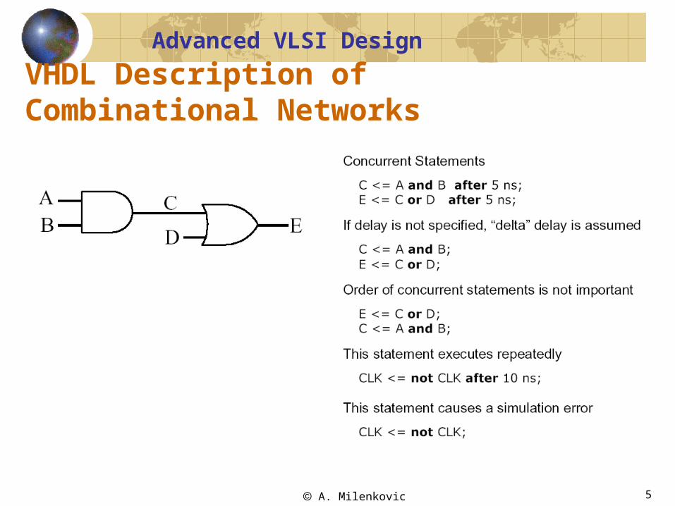
VHDL Description of Combinational Networks
A. Milenkovic 6
Advanced VLSI Design
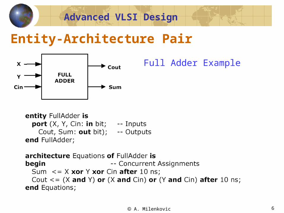
Entity-Architecture Pair
Full Adder Example

A. Milenkovic 7
Advanced VLSI Design
VHDL Program Structure

A. Milenkovic 8
Advanced VLSI Design
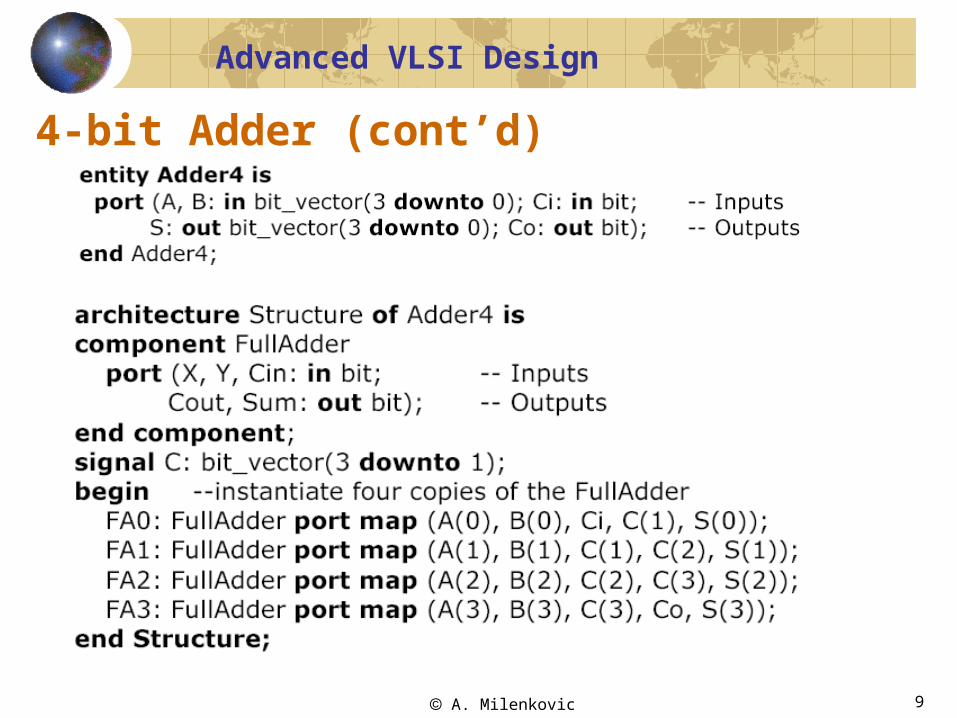
4-bit Adder
A. Milenkovic 9
Advanced VLSI Design
4-bit Adder (cont’d)
A. Milenkovic 10
Advanced VLSI Design
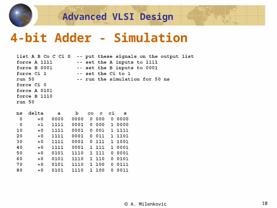
4-bit Adder - Simulation
A. Milenkovic 11
Advanced VLSI Design
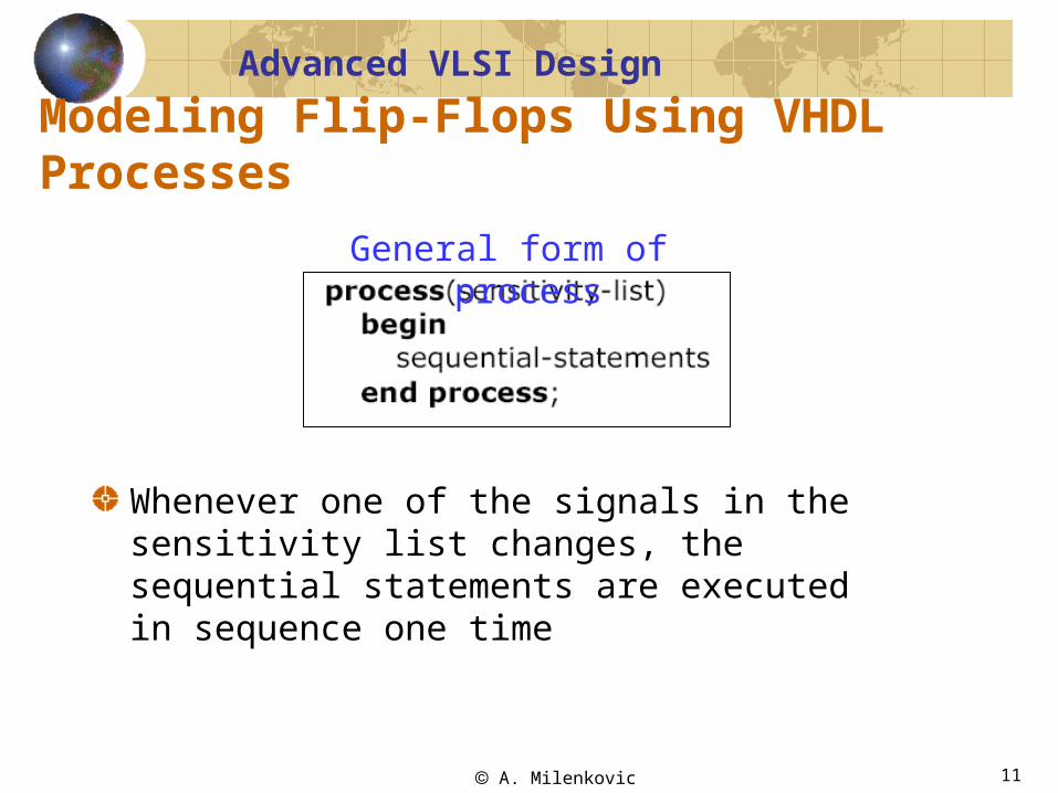
Modeling Flip-Flops Using VHDL Processes
Whenever one of the signals in the sensitivity list changes, the sequential statements are executed in sequence one time
General form of process
A. Milenkovic 12
Advanced VLSI Design
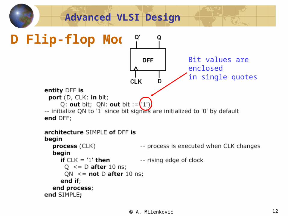
D Flip-flop Model
Bit values are enclosed in single quotes

A. Milenkovic 13
Advanced VLSI Design
JK Flip-Flop Model
A. Milenkovic 14
Advanced VLSI Design
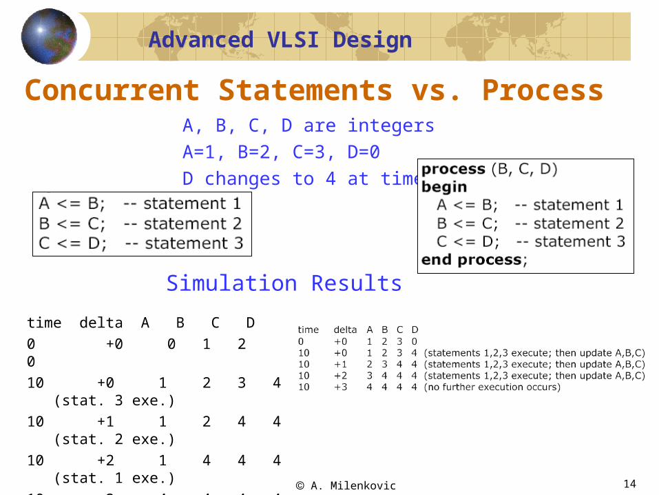
Concurrent Statements vs. Process
Simulation Results
A, B, C, D are integers
A=1, B=2, C=3, D=0
D changes to 4 at time 10
time delta A B C D
0 +0 0 1 2 0
10 +0 1 2 3 4 (stat. 3 exe.)
10 +1 1 2 4 4 (stat. 2 exe.)
10 +2 1 4 4 4 (stat. 1 exe.)
10 +3 4 4 4 4 (no exec.)
A. Milenkovic 15
Advanced VLSI Design
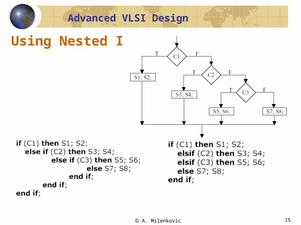
Using Nested IFs and ELSEIFs

A. Milenkovic 16
Advanced VLSI Design
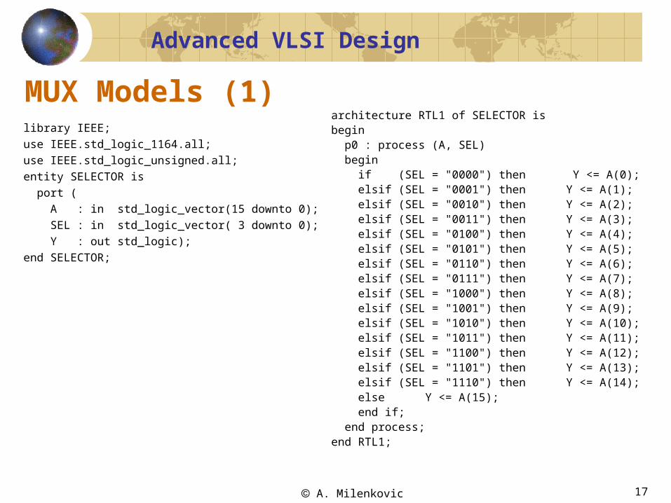
VHDL Models for a MUX
Sel represents the integerequivalent of a 2-bit binary number with bits A and B
If a MUX model is used inside a process, the MUX can be modeled using a CASE statement(cannot use a concurrent statement):
A. Milenkovic 17
Advanced VLSI Design
MUX Models (1)library IEEE;
use IEEE.std_logic_1164.all;
use IEEE.std_logic_unsigned.all;
entity SELECTOR is
port (
A : in std_logic_vector(15 downto 0);
SEL : in std_logic_vector( 3 downto 0);
Y : out std_logic);
end SELECTOR;
architecture RTL1 of SELECTOR isbegin p0 : process (A, SEL) begin if (SEL = "0000") then Y <= A(0); elsif (SEL = "0001") then Y <= A(1); elsif (SEL = "0010") then Y <= A(2); elsif (SEL = "0011") then Y <= A(3); elsif (SEL = "0100") then Y <= A(4); elsif (SEL = "0101") then Y <= A(5); elsif (SEL = "0110") then Y <= A(6); elsif (SEL = "0111") then Y <= A(7); elsif (SEL = "1000") then Y <= A(8); elsif (SEL = "1001") then Y <= A(9); elsif (SEL = "1010") then Y <= A(10); elsif (SEL = "1011") then Y <= A(11); elsif (SEL = "1100") then Y <= A(12); elsif (SEL = "1101") then Y <= A(13); elsif (SEL = "1110") then Y <= A(14); else Y <= A(15); end if; end process;end RTL1;
A. Milenkovic 18
Advanced VLSI Design
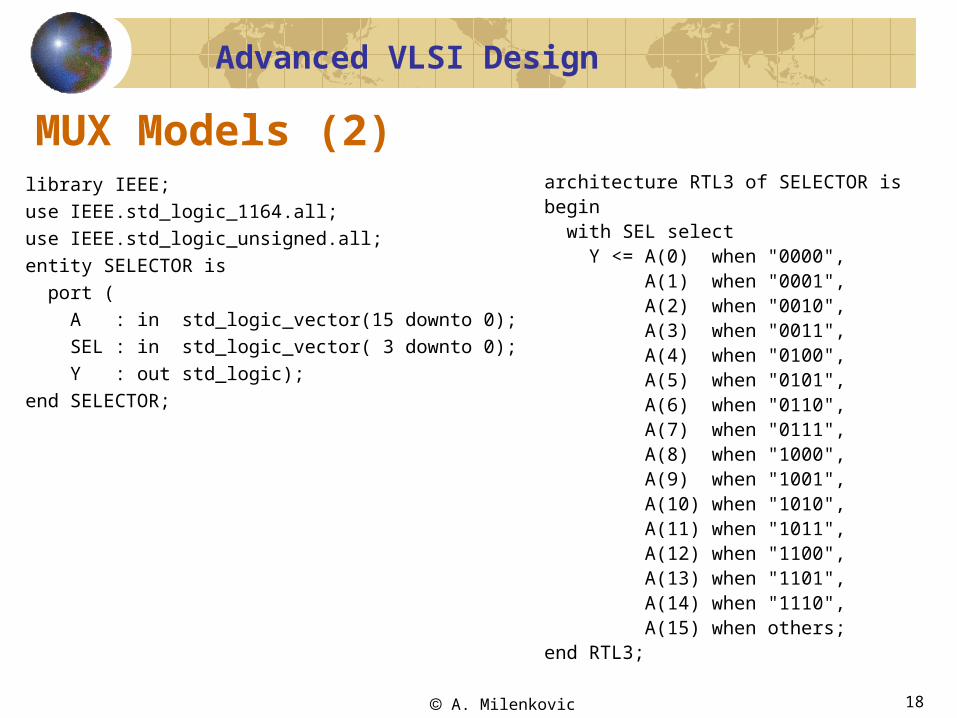
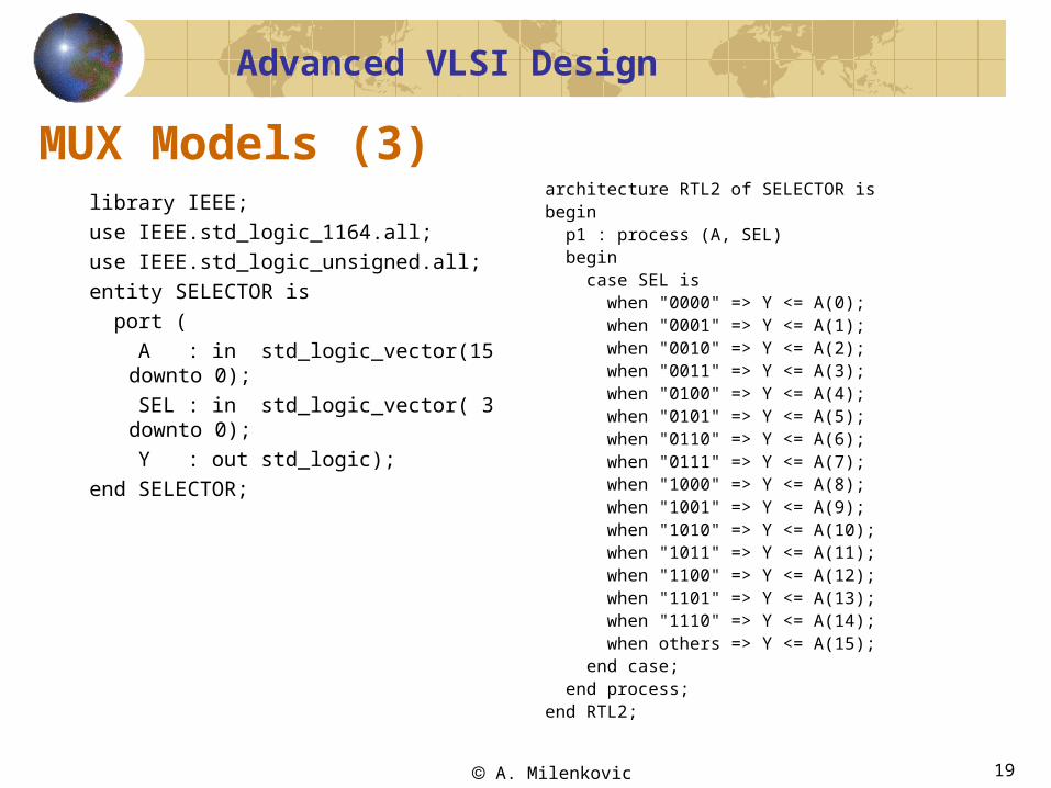
MUX Models (2)library IEEE;
use IEEE.std_logic_1164.all;
use IEEE.std_logic_unsigned.all;
entity SELECTOR is
port (
A : in std_logic_vector(15 downto 0);
SEL : in std_logic_vector( 3 downto 0);
Y : out std_logic);
end SELECTOR;
architecture RTL3 of SELECTOR isbegin with SEL select Y <= A(0) when "0000", A(1) when "0001", A(2) when "0010", A(3) when "0011", A(4) when "0100", A(5) when "0101", A(6) when "0110", A(7) when "0111", A(8) when "1000", A(9) when "1001", A(10) when "1010", A(11) when "1011", A(12) when "1100", A(13) when "1101", A(14) when "1110", A(15) when others; end RTL3;
A. Milenkovic 19
Advanced VLSI Design
MUX Models (3)library IEEE;
use IEEE.std_logic_1164.all;
use IEEE.std_logic_unsigned.all;
entity SELECTOR is
port (
A : in std_logic_vector(15 downto 0);
SEL : in std_logic_vector( 3 downto 0);
Y : out std_logic);
end SELECTOR;
architecture RTL2 of SELECTOR isbegin p1 : process (A, SEL) begin case SEL is when "0000" => Y <= A(0); when "0001" => Y <= A(1); when "0010" => Y <= A(2); when "0011" => Y <= A(3); when "0100" => Y <= A(4); when "0101" => Y <= A(5); when "0110" => Y <= A(6); when "0111" => Y <= A(7); when "1000" => Y <= A(8); when "1001" => Y <= A(9); when "1010" => Y <= A(10); when "1011" => Y <= A(11); when "1100" => Y <= A(12); when "1101" => Y <= A(13); when "1110" => Y <= A(14); when others => Y <= A(15); end case; end process;end RTL2;
A. Milenkovic 20
Advanced VLSI Design
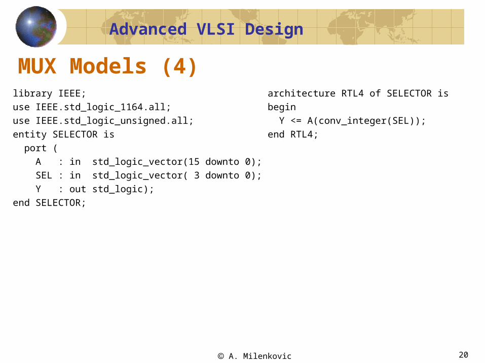
MUX Models (4)library IEEE;
use IEEE.std_logic_1164.all;
use IEEE.std_logic_unsigned.all;
entity SELECTOR is
port (
A : in std_logic_vector(15 downto 0);
SEL : in std_logic_vector( 3 downto 0);
Y : out std_logic);
end SELECTOR;
architecture RTL4 of SELECTOR is
begin
Y <= A(conv_integer(SEL));
end RTL4;
A. Milenkovic 21
Advanced VLSI Design
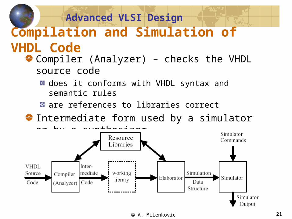
Compilation and Simulation of VHDL CodeCompiler (Analyzer) – checks the VHDL source code
does it conforms with VHDL syntax and semantic rules
are references to libraries correct
Intermediate form used by a simulator or by a synthesizer
Elaborationcreate ports, allocate memory storage, create interconnections, ...
establish mechanism for executing of VHDL processes
A. Milenkovic 22
Advanced VLSI Design
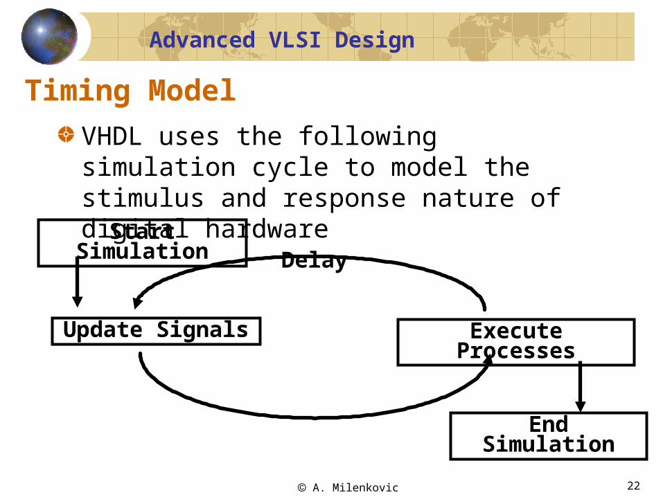
Timing Model
VHDL uses the following simulation cycle to model the stimulus and response nature of digital hardware
DelayStart
Simulation
Update Signals Execute Processes
End Simulation

A. Milenkovic 23
Advanced VLSI Design
Delay Types
All VHDL signal assignment statements prescribe an amount of time that must transpire before the signal assumes its new value
This prescribed delay can be in one of three forms:
Transport -- prescribes propagation delay only
Inertial -- prescribes propagation delay and minimum input pulse width
Delta -- the default if no delay time is explicitly specified
Inputdelay
Output

A. Milenkovic 24
Advanced VLSI Design
Transport DelayTransport delay must be explicitly specified
I.e. keyword “TRANSPORT” must be used
Signal will assume its new value after specified delay
Input Output
0 5 10 15 20 25 30 35
Input
Output
-- TRANSPORT delay exampleOutput <= TRANSPORT NOT Input AFTER 10 ns;
A. Milenkovic 25
Advanced VLSI Design
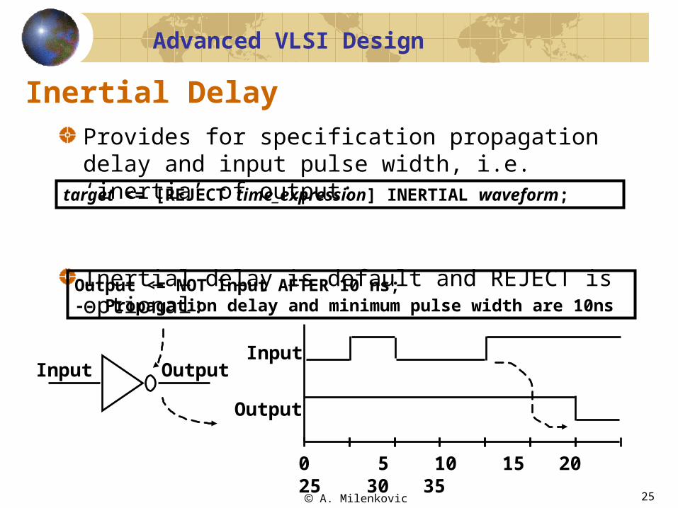
Inertial DelayProvides for specification propagation delay and input pulse width, i.e. ‘inertia’ of output:
Inertial delay is default and REJECT is optional:
Input
Output
0 5 10 15 20 25 30 35
Input Output
target <= [REJECT time_expression] INERTIAL waveform;
Output <= NOT Input AFTER 10 ns;-- Propagation delay and minimum pulse width are 10ns
A. Milenkovic 26
Advanced VLSI Design
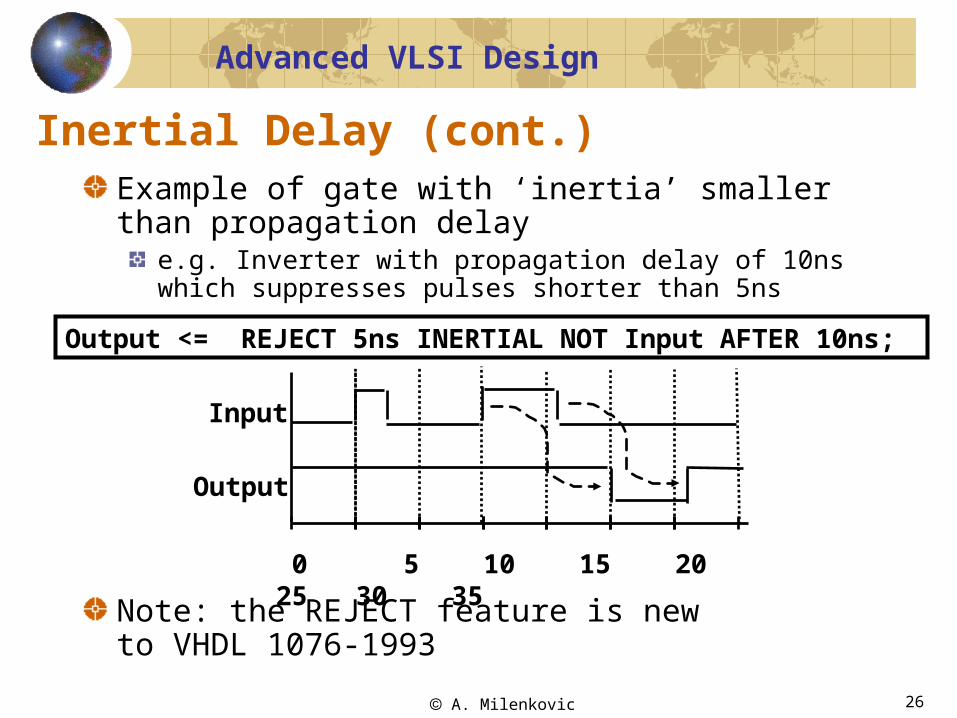
Inertial Delay (cont.)Example of gate with ‘inertia’ smaller than propagation delay
e.g. Inverter with propagation delay of 10ns which suppresses pulses shorter than 5ns
Note: the REJECT feature is new to VHDL 1076-1993
Input
Output
0 5 10 15 20 25 30 35
Output <= REJECT 5ns INERTIAL NOT Input AFTER 10ns;
A. Milenkovic 27
Advanced VLSI Design
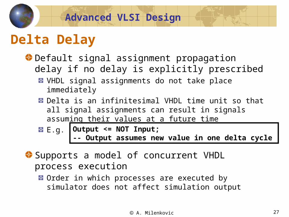
Delta DelayDefault signal assignment propagation delay if no delay is explicitly prescribed
VHDL signal assignments do not take place immediately
Delta is an infinitesimal VHDL time unit so that all signal assignments can result in signals assuming their values at a future time
E.g.
Supports a model of concurrent VHDL process execution
Order in which processes are executed by simulator does not affect simulation output
Output <= NOT Input;-- Output assumes new value in one delta cycle
A. Milenkovic 28
Advanced VLSI Design
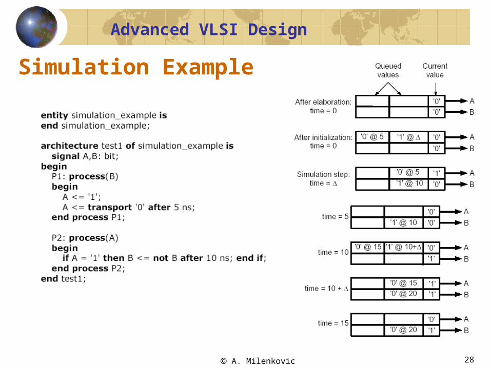
Simulation Example

A. Milenkovic 29
Advanced VLSI Design
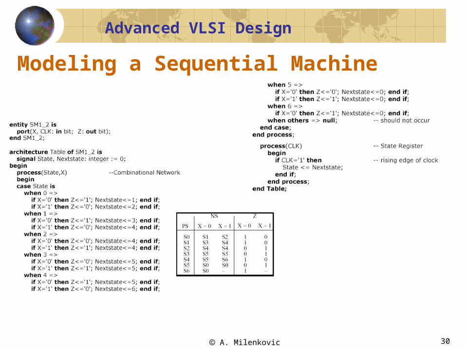
Modeling a Sequential MachineMealy Machine for
8421 BCD to 8421 BCD + 3 bit serial converter
How to model this in VHDL?
A. Milenkovic 30
Advanced VLSI Design
Modeling a Sequential Machine
A. Milenkovic 31
Advanced VLSI Design
Behavioral VHDL Model
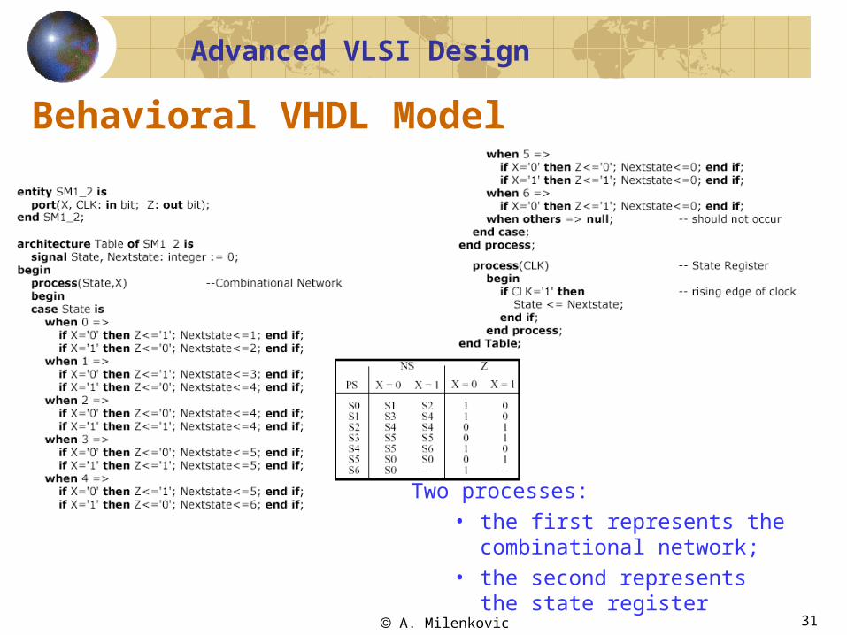
Two processes:
• the first represents the combinational network;
• the second represents the state register

A. Milenkovic 32
Advanced VLSI Design
Simulation of the VHDL ModelSimulation command file:
Waveforms:
A. Milenkovic 33
Advanced VLSI Design
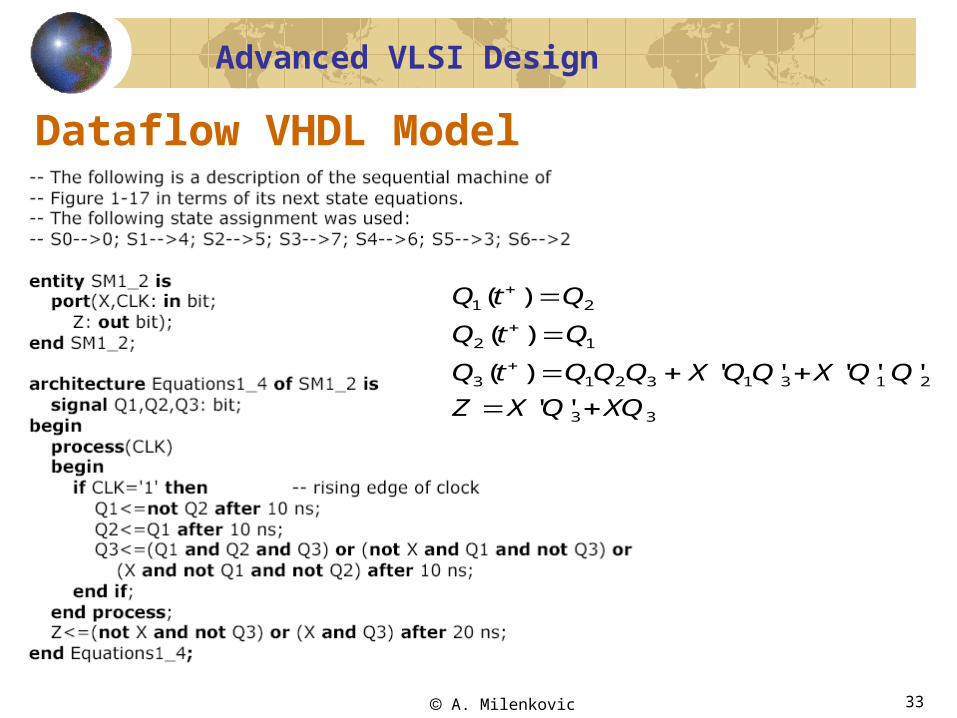
Dataflow VHDL Model
33
21313213
12
21
''
''''')(
)(
)(
XQQXZ
QQXQQXQQQtQ
QtQ
QtQ

A. Milenkovic 34
Advanced VLSI Design
Structural Model
Package bit_pack is a part of library BITLIB –
includes gates, flip-flops, counters
(See Appendix B for details)

A. Milenkovic 35
Advanced VLSI Design
Simulation of the Structural ModelSimulation command file:
Waveforms:

A. Milenkovic 36
Advanced VLSI Design
Wait Statements... an alternative to a sensitivity list
Note: a process cannot have both wait statement(s)and a sensitivity list
Generic form of a process with wait statement(s)
process
begin
sequential-statements
wait statement
sequential-statements
wait-statement
...
end process;
How wait statements work?• Execute seq. statement until a wait statement is encountered.
• Wait until the specified condition is satisfied.
• Then execute the next set of sequential statements until the next wait statement is encountered.
• ...
• When the end of the process is reached start over again at the beginning.

A. Milenkovic 37
Advanced VLSI Design
Forms of Wait Statements
Wait on until one of the signals in the sensitivity list changes
Wait forwaits until the time specified by the time expression has elapsedWhat is this:wait for 0 ns;
Wait untilthe boolean expression is evaluated whenever one of the signals in the expression changes, and the process continues execution when the expression evaluates to TRUE
wait on sensitivity-list;
wait for time-expression;
wait until boolean-expression;
A. Milenkovic 38
Advanced VLSI Design
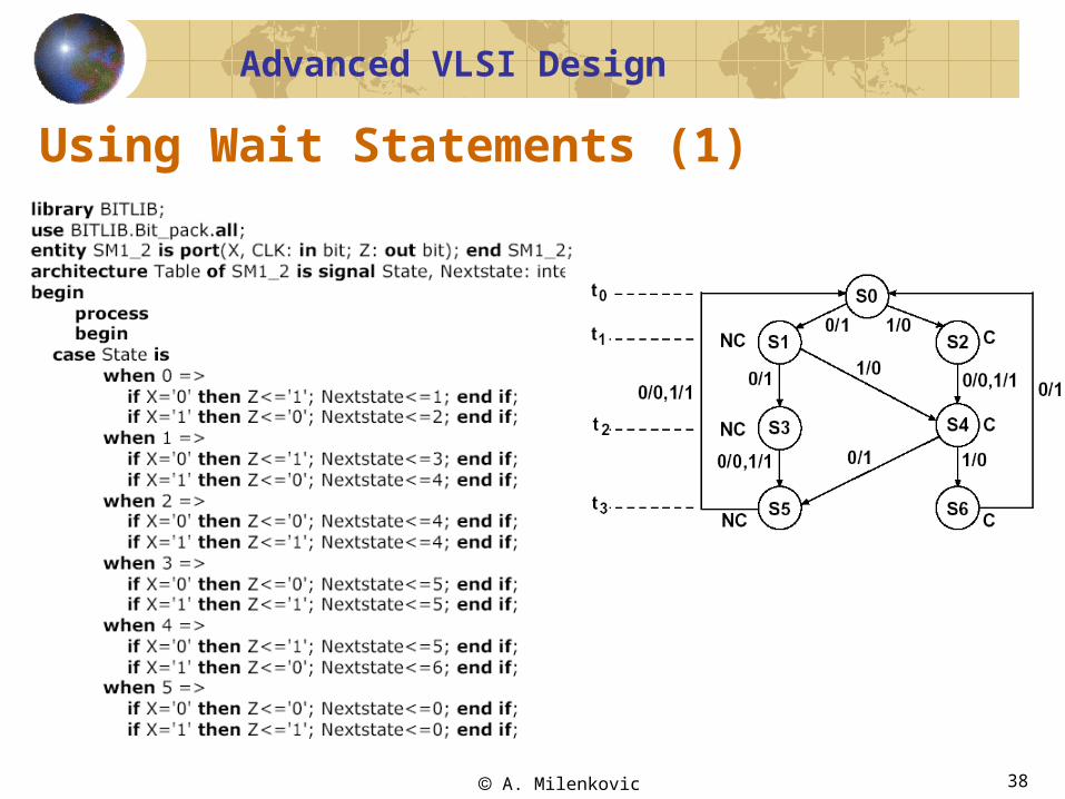
Using Wait Statements (1)
A. Milenkovic 39
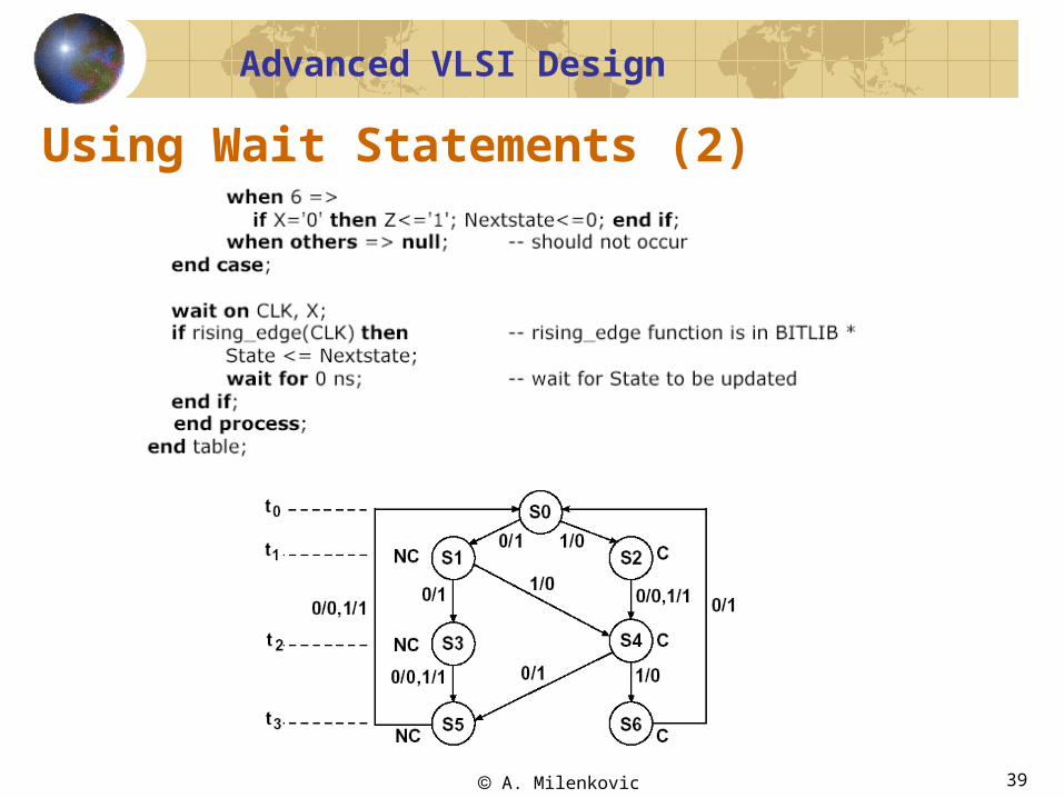
Advanced VLSI Design
Using Wait Statements (2)
A. Milenkovic 40
Advanced VLSI Design
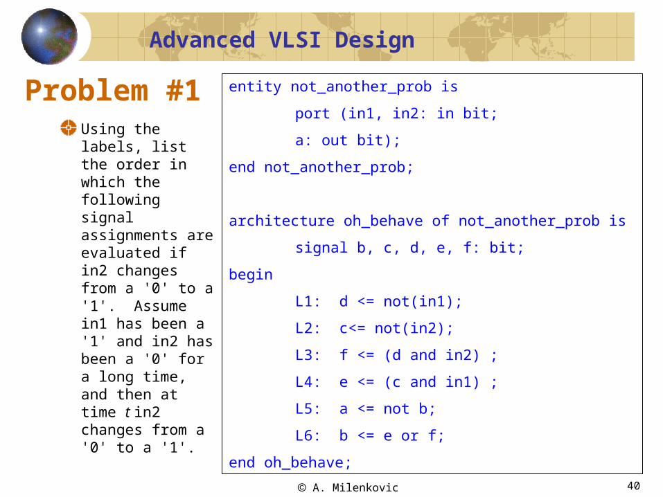
Problem #1Using the labels, list the order in which the following signal assignments are evaluated if in2 changes from a '0' to a '1'. Assume in1 has been a '1' and in2 has been a '0' for a long time, and then at time t in2 changes from a '0' to a '1'.
entity not_another_prob is
port (in1, in2: in bit;
a: out bit);
end not_another_prob;
architecture oh_behave of not_another_prob is
signal b, c, d, e, f: bit;
begin
L1: d <= not(in1);
L2: c<= not(in2);
L3: f <= (d and in2) ;
L4: e <= (c and in1) ;
L5: a <= not b;
L6: b <= e or f;
end oh_behave;
A. Milenkovic 41
Advanced VLSI Design
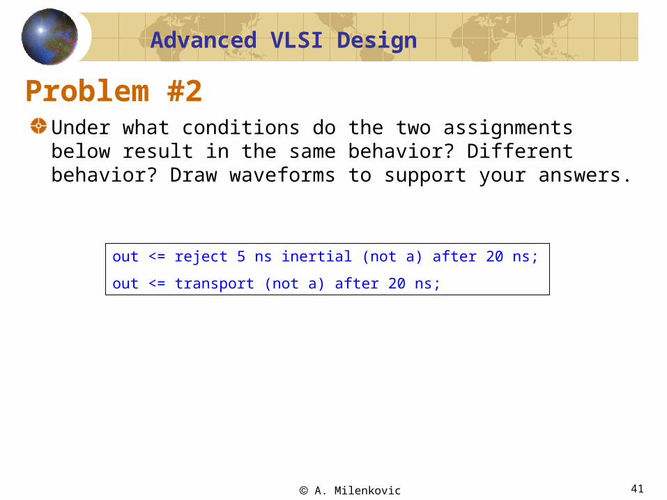
Problem #2Under what conditions do the two assignments below result in the same behavior? Different behavior? Draw waveforms to support your answers.
out <= reject 5 ns inertial (not a) after 20 ns;
out <= transport (not a) after 20 ns;
A. Milenkovic 42
Advanced VLSI Design
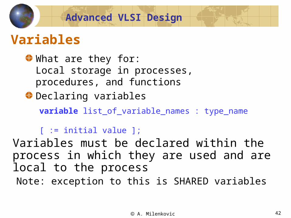
VariablesWhat are they for: Local storage in processes, procedures, and functions
Declaring variables
variable list_of_variable_names : type_name
[ := initial value ];
Variables must be declared within the process in which they are used and are local to the processNote: exception to this is SHARED variables

A. Milenkovic 43
Advanced VLSI Design
SignalsSignals must be declared outside a processDeclaration formsignal list_of_signal_names : type_name [ := initial value ];
• Declared in an architecture can be used anywhere within that architecture
A. Milenkovic 44
Advanced VLSI Design
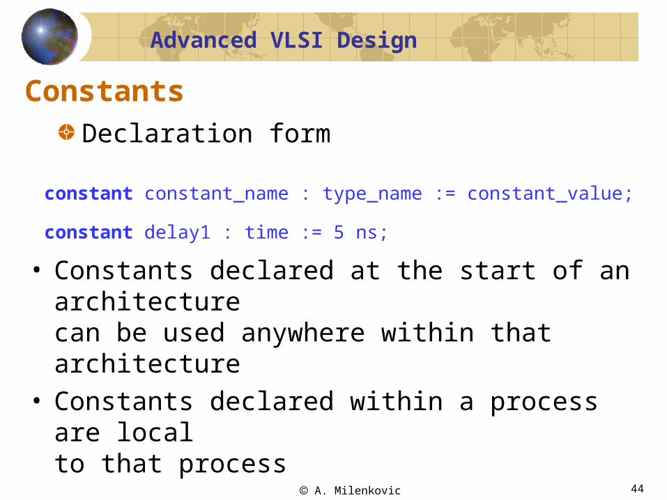
ConstantsDeclaration form
constant constant_name : type_name := constant_value;
• Constants declared at the start of an architecturecan be used anywhere within that architecture
• Constants declared within a process are localto that process
constant delay1 : time := 5 ns;
A. Milenkovic 45
Advanced VLSI Design
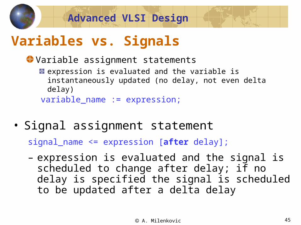
Variables vs. SignalsVariable assignment statements
expression is evaluated and the variable is instantaneously updated (no delay, not even delta delay)
variable_name := expression;
• Signal assignment statementsignal_name <= expression [after delay];
– expression is evaluated and the signal is scheduled to change after delay; if no delay is specified the signal is scheduled to be updated after a delta delay
A. Milenkovic 46
Advanced VLSI Design
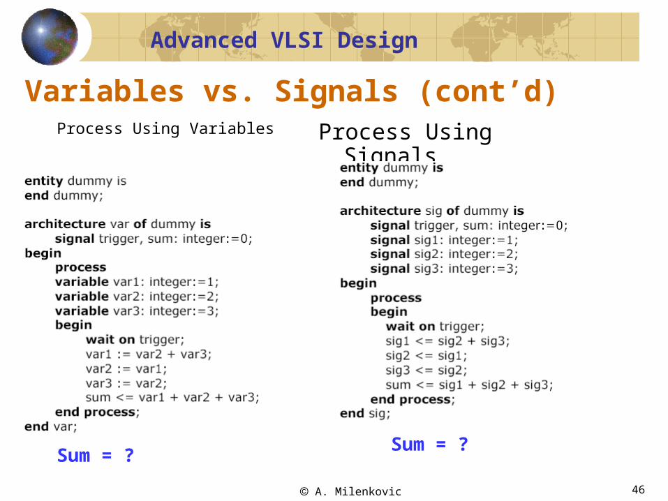
Variables vs. Signals (cont’d)Process Using Variables Process Using Signals
Sum = ?Sum = ?
A. Milenkovic 47
Advanced VLSI Design
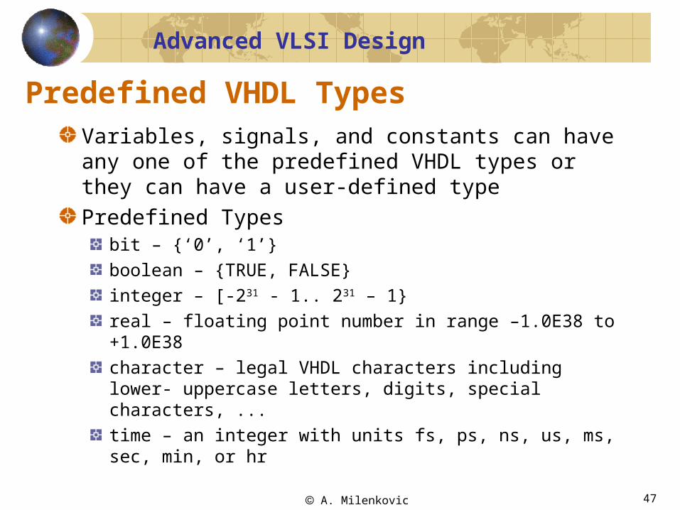
Predefined VHDL TypesVariables, signals, and constants can have any one of the predefined VHDL types or they can have a user-defined type
Predefined Typesbit – {‘0’, ‘1’}
boolean – {TRUE, FALSE}
integer – [-231 - 1.. 231 – 1}
real – floating point number in range –1.0E38 to +1.0E38
character – legal VHDL characters including lower- uppercase letters, digits, special characters, ...
time – an integer with units fs, ps, ns, us, ms, sec, min, or hr
A. Milenkovic 48
Advanced VLSI Design
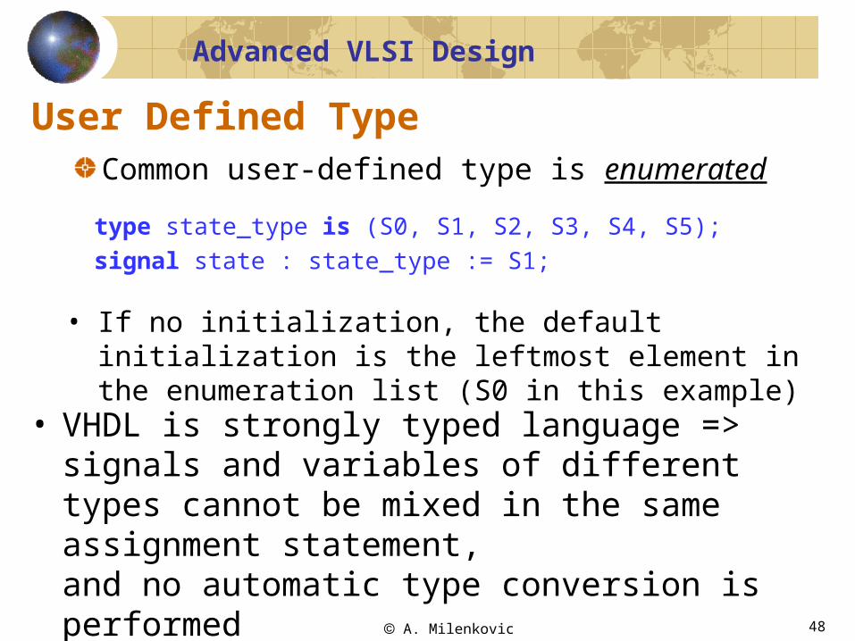
User Defined TypeCommon user-defined type is enumerated
type state_type is (S0, S1, S2, S3, S4, S5);
signal state : state_type := S1;
• If no initialization, the default initialization is the leftmost element in the enumeration list (S0 in this example)
• VHDL is strongly typed language =>signals and variables of different types cannot be mixed in the same assignment statement,and no automatic type conversion is performed
A. Milenkovic 49
Advanced VLSI Design
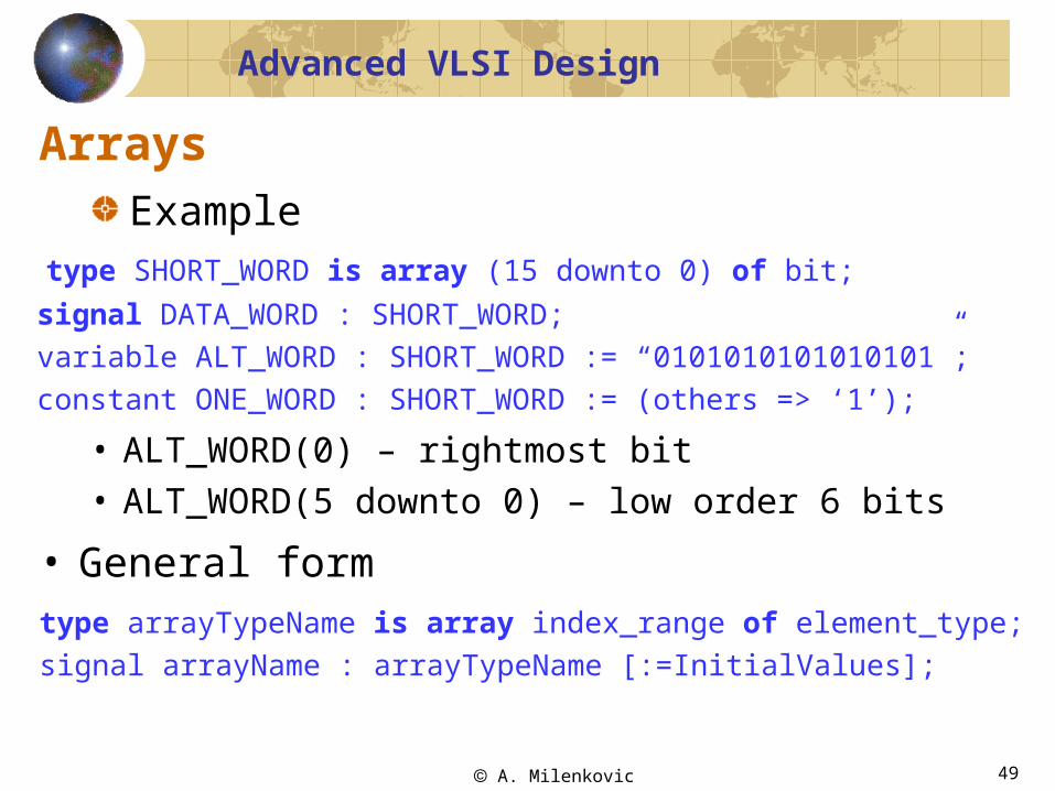
ArraysExample
type SHORT_WORD is array (15 downto 0) of bit;
signal DATA_WORD : SHORT_WORD;
variable ALT_WORD : SHORT_WORD := “0101010101010101”;
constant ONE_WORD : SHORT_WORD := (others => ‘1’);
• ALT_WORD(0) – rightmost bit• ALT_WORD(5 downto 0) – low order 6 bits
• General formtype arrayTypeName is array index_range of element_type;
signal arrayName : arrayTypeName [:=InitialValues];

A. Milenkovic 50
Advanced VLSI Design
Arrays (cont’d)
Multidimensional arraystype matrix4x3 is array (1 to 4, 1 to 3) of integer;
variable matrixA: matrix4x3 := ((1,2,3), (4,5,6), (7,8,9), (10,11,12));
• matrixA(3, 2) = ?
• Unconstrained array typetype intvec is array (natural range<>) of integer;
• range must be specified when the array object is declared
signal intvec5 : intvec(1 to 5) := (3,2,6,8,1);
type matrix is array (natural range<>,natural range<>) of integer;
A. Milenkovic 51
Advanced VLSI Design
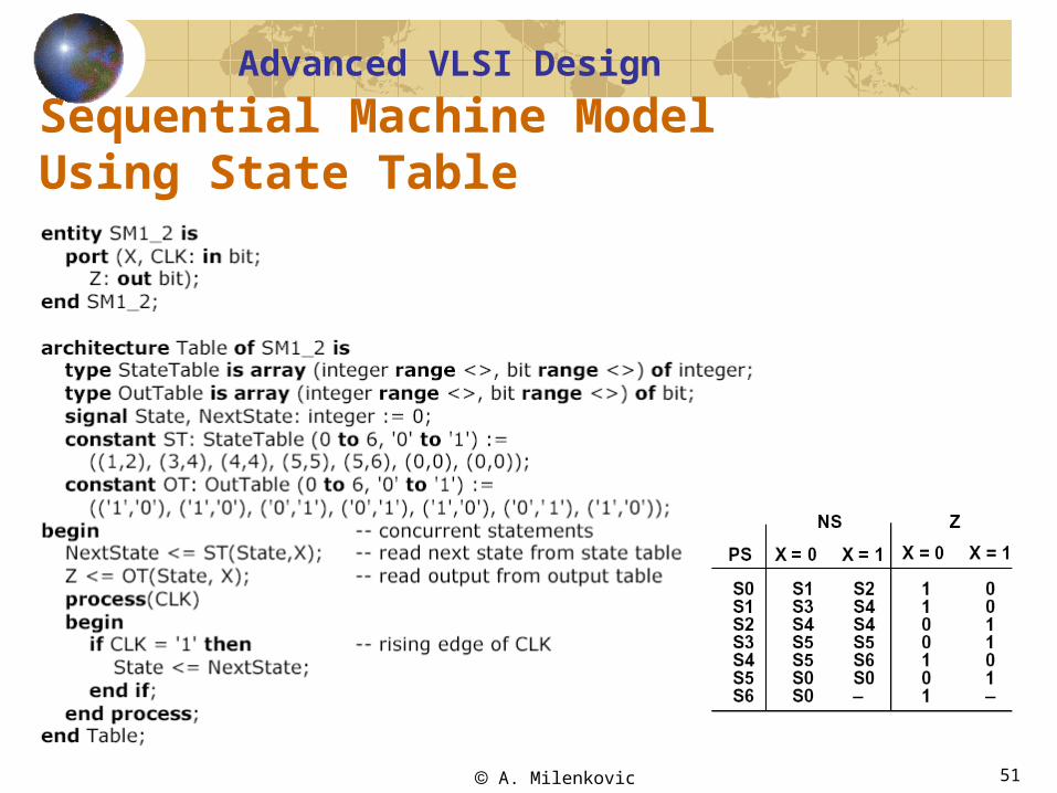
Sequential Machine Model Using State Table
A. Milenkovic 52
Advanced VLSI Design
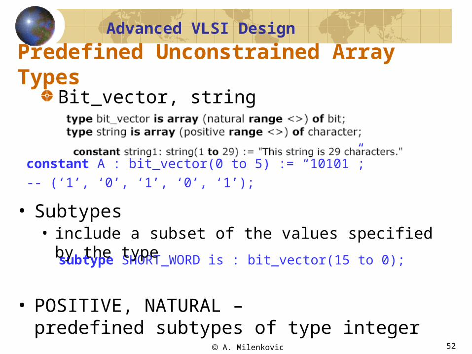
Predefined Unconstrained Array Types
Bit_vector, string
constant A : bit_vector(0 to 5) := “10101”;
-- (‘1’, ‘0’, ‘1’, ‘0’, ‘1’);
• Subtypes
subtype SHORT_WORD is : bit_vector(15 to 0);
• POSITIVE, NATURAL – predefined subtypes of type integer
• include a subset of the values specified by the type

A. Milenkovic 53
Advanced VLSI Design
VHDL Operators
Binary logical operators: and or nand nor xor xnor
Relational: = /= < <= > >=
Shift: sll srl sla sra rol ror
Adding: + - & (concatenation)
Unary sign: + -
Multiplying: * / mod rem
Miscellaneous: not abs **
• Class 7 has the highest precedence (applied first),followed by class 6, then class 5, etc
A. Milenkovic 54
Advanced VLSI Design
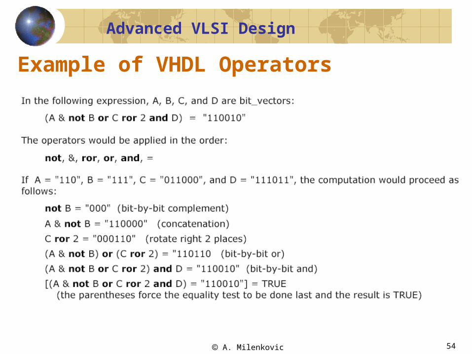
Example of VHDL Operators

A. Milenkovic 55
Advanced VLSI Design
Example of Shift Operators (cont’d)
A. Milenkovic 56
Advanced VLSI Design
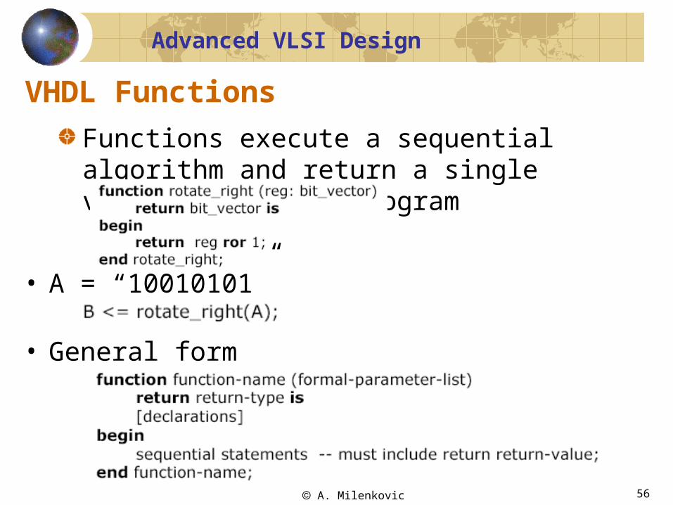
VHDL Functions
Functions execute a sequential algorithm and return a single value to calling program
• A = “10010101”
• General form

A. Milenkovic 57
Advanced VLSI Design
For Loops
A. Milenkovic 58
Advanced VLSI Design
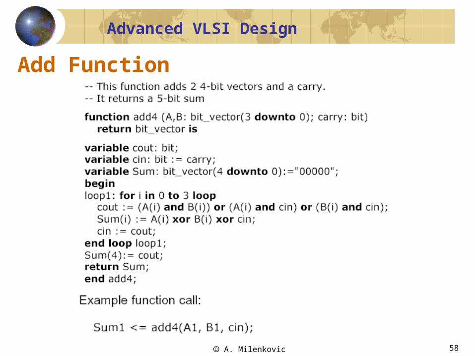
Add Function
A. Milenkovic 59
Advanced VLSI Design
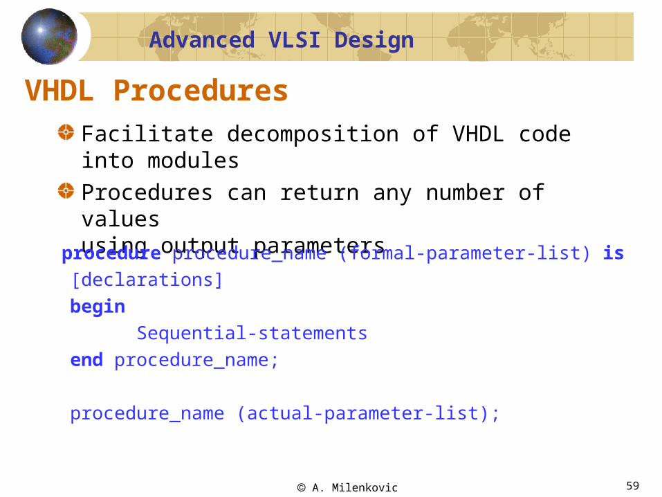
VHDL ProceduresFacilitate decomposition of VHDL code into modules
Procedures can return any number of values using output parameters
procedure procedure_name (formal-parameter-list) is
[declarations]
begin
Sequential-statements
end procedure_name;
procedure_name (actual-parameter-list);

A. Milenkovic 60
Advanced VLSI Design
Procedure for Adding Bit_vectors

A. Milenkovic 61
Advanced VLSI Design
Parameters for Subprogram Calls

A. Milenkovic 62
Advanced VLSI Design
Packages and Libraries
Provide a convenient way of referencing frequently used functions and components
• Package declaration
• Package body [optional]

A. Milenkovic 63
Advanced VLSI Design
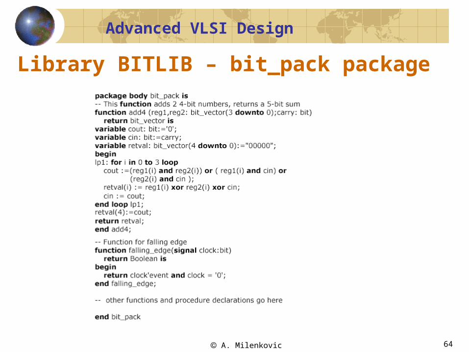
Library BITLIB – bit_pack package
A. Milenkovic 64
Advanced VLSI Design
Library BITLIB – bit_pack package

CPE 626: Advanced VLSI DesignVHDL Recap (Part II)
Department of Electrical and Computer Engineering University of Alabama in Huntsville

A. Milenkovic 66
Advanced VLSI Design
Additional Topics in VHDLAttributesTransport and Inertial DelaysOperator OverloadingMultivalued Logic and Signal ResolutionIEEE 1164 Standard LogicGenericsGenerate StatementsSynthesis of VHDL CodeSynthesis ExamplesFiles and Text IO
A. Milenkovic 67
Advanced VLSI Design
Signal Attributes
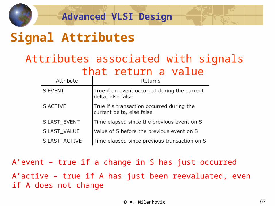
Attributes associated with signals that return a value
A’event – true if a change in S has just occurred
A’active – true if A has just been reevaluated, even if A does not change

A. Milenkovic 68
Advanced VLSI Design
Review: Signal Attributes (cont’d)
Attributes that create a signal
A. Milenkovic 69
Advanced VLSI Design
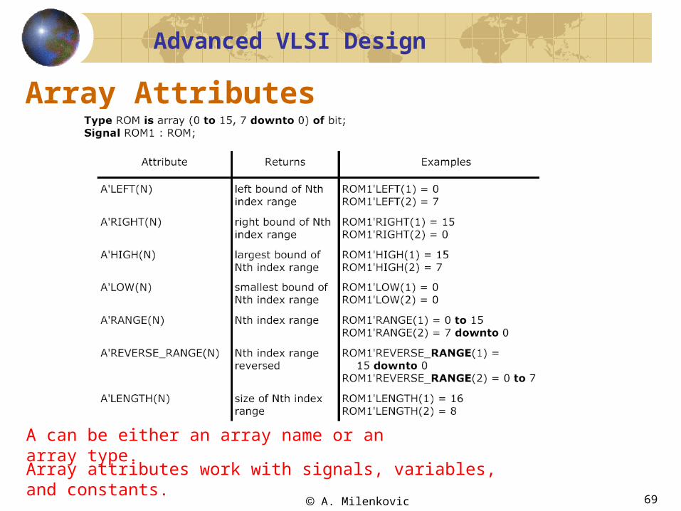
Array Attributes
A can be either an array name or an array type.
Array attributes work with signals, variables, and constants.

A. Milenkovic 70
Advanced VLSI Design
Transport and Inertial Delay

A. Milenkovic 71
Advanced VLSI Design
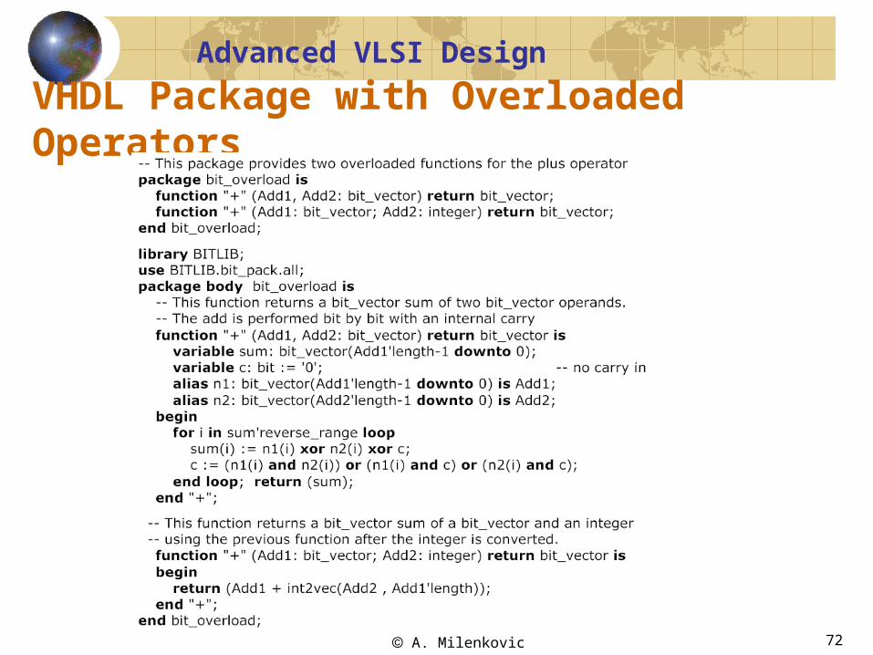
Review: Operator OverloadingOperators +, - operate on integers
Write procedures for bit vector addition/subtractionaddvec, subvec
Operator overloading allows using + operator to implicitly call an appropriate addition function
How does it work?When compiler encounters a function declaration in which the function name is an operator enclosed in double quotes, the compiler treats the function as an operator overloading (“+”)
when a “+” operator is encountered, the compiler automatically checks the types of operands and calls appropriate functions
A. Milenkovic 72
Advanced VLSI Design
VHDL Package with Overloaded Operators

A. Milenkovic 73
Advanced VLSI Design
Multivalued Logic
Bit (0, 1)
Tristate buffers and buses =>high impedance state ‘Z’
Unknown state ‘X’ e. g., a gate is driven by ‘Z’, output is unknown
a signal is simultaneously driven by ‘0’ and ‘1’
A. Milenkovic 74
Advanced VLSI Design
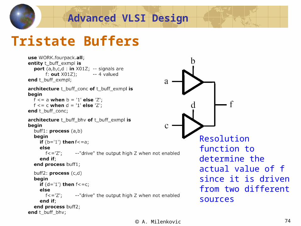
Tristate Buffers
Resolution function to determine the actual value of f since it is driven from two different sources

A. Milenkovic 75
Advanced VLSI Design
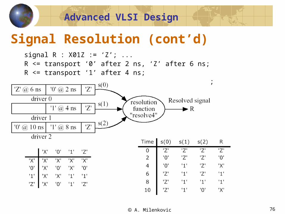
Signal Resolution
VHDL signals may either be resolved or unresolved
Resolved signals have an associated resolution function
Bit type is unresolved – there is no resolution function
if you drive a bit signal to two different values in two concurrent statements, the compiler will generate an error
A. Milenkovic 76
Advanced VLSI Design
Signal Resolution (cont’d)signal R : X01Z := ‘Z’; ...R <= transport ‘0’ after 2 ns, ‘Z’ after 6 ns;R <= transport ‘1’ after 4 ns;R <= transport ‘1’ after 8 ns, ‘0’ after 10 ns;
A. Milenkovic 77
Advanced VLSI Design
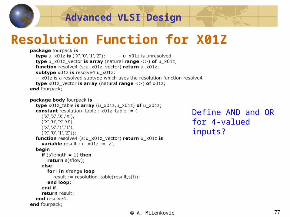
Resolution Function for X01Z
Define AND and OR for 4-valued inputs?
A. Milenkovic 78
Advanced VLSI Design
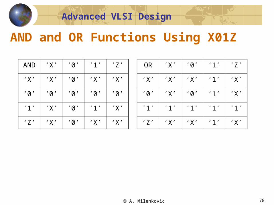
AND and OR Functions Using X01Z
AND ‘X’ ‘0’ ‘1’ ‘Z’
‘X’ ‘X’ ‘0’ ‘X’ ‘X’
‘0’ ‘0’ ‘0’ ‘0’ ‘0’
‘1’ ‘X’ ‘0’ ‘1’ ‘X’
‘Z’ ‘X’ ‘0’ ‘X’ ‘X’
OR ‘X’ ‘0’ ‘1’ ‘Z’
‘X’ ‘X’ ‘X’ ‘1’ ‘X’
‘0’ ‘X’ ‘0’ ‘1’ ‘X’
‘1’ ‘1’ ‘1’ ‘1’ ‘1’
‘Z’ ‘X’ ‘X’ ‘1’ ‘X’

A. Milenkovic 79
Advanced VLSI Design
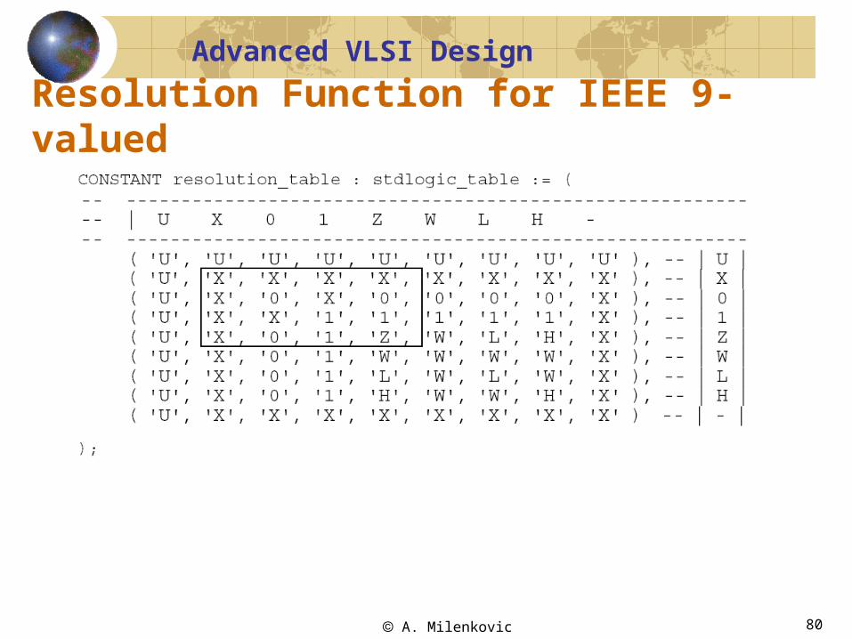
IEEE 1164 Standard Logic9-valued logic system
‘U’ – Uninitialized‘X’ – Forcing Unknown‘0’ – Forcing 0‘1’ – Forcing 1‘Z’ – High impedance‘W’ – Weak unknown‘L’ – Weak 0‘H’ – Weak 1‘-’ – Don’t care
If forcing and weak signal are tied together, the forcing signal dominates.
Useful in modeling the internal operation of certain types of ICs.
In this course we use a subset of the IEEE values: X10Z
A. Milenkovic 80
Advanced VLSI Design
Resolution Function for IEEE 9-valued

A. Milenkovic 81
Advanced VLSI Design
AND Table for IEEE 9-valued

A. Milenkovic 82
Advanced VLSI Design
AND Function for std_logic_vectors

A. Milenkovic 83
Advanced VLSI Design
Generics
Used to specify parameters for a component in such a way that the parameter values must be specified when the component is instantiated
Example: rise/fall time modeling

A. Milenkovic 84
Advanced VLSI Design
Rise/Fall Time Modeling Using Generics
A. Milenkovic 85
Advanced VLSI Design
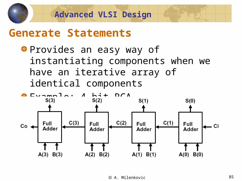
Generate Statements
Provides an easy way of instantiating components when we have an iterative array of identical components
Example: 4-bit RCA
A. Milenkovic 86
Advanced VLSI Design
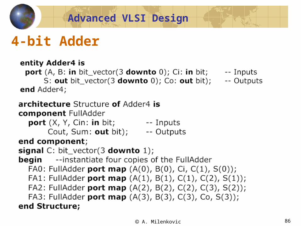
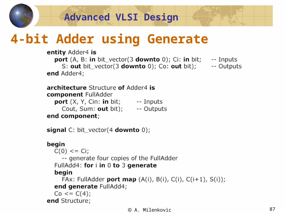
4-bit Adder
A. Milenkovic 87
Advanced VLSI Design
4-bit Adder using Generate

A. Milenkovic 88
Advanced VLSI Design
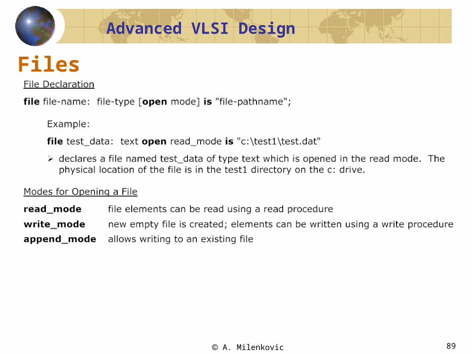
Files
File input/output in VHDL
Used in test benchesSource of test data
Storage for test results
VHDL provides a standard TEXTIO packageread/write lines of text
A. Milenkovic 89
Advanced VLSI Design
Files
A. Milenkovic 90
Advanced VLSI Design
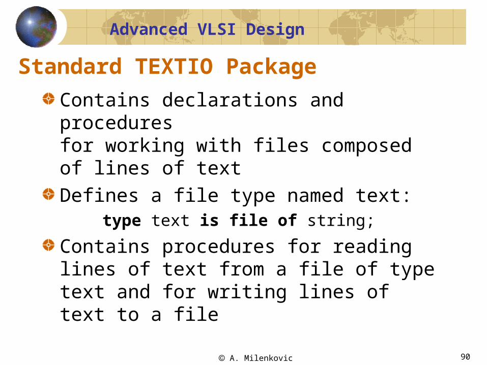
Standard TEXTIO Package
Contains declarations and procedures for working with files composed of lines of text
Defines a file type named text:type text is file of string;
Contains procedures for reading lines of text from a file of type text and for writing lines of text to a file
A. Milenkovic 91
Advanced VLSI Design
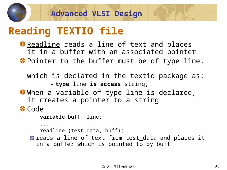
Reading TEXTIO fileReadline reads a line of text and places it in a buffer with an associated pointerPointer to the buffer must be of type line, which is declared in the textio package as:
– type line is access string;
When a variable of type line is declared, it creates a pointer to a stringCode
variable buff: line;...readline (test_data, buff);
reads a line of text from test_data and places it in a buffer which is pointed to by buff

A. Milenkovic 92
Advanced VLSI Design
Extracting Data from the Line Buffer
To extract data from the line buffer, call a read procedure one or more times
For example, if bv4 is a bit_vector of length four, the call
read(buff, bv4)
extracts a 4-bit vector from the buffer, sets bv4 equal to this vector, and adjusts the pointer buff to point to the next character in the buffer. Another call to read will then extract the next data object from the line buffer.

A. Milenkovic 93
Advanced VLSI Design
Extracting Data from the Line Buffer (cont’d)
TEXTIO provides overloaded read procedures to read data of types bit, bit_vector, boolean, character, integer, real, string, and time from buffer
Read forms• read(pointer, value)
• read(pointer, value, good)
good is boolean that returns TRUE if the read is successful and FALSE if it is not
type and size of value determines which of the read procedures is called
character, strings, and bit_vectors within files of type text are not delimited by quotes

A. Milenkovic 94
Advanced VLSI Design
Writing to TEXTIO filesCall one or more write procedures to write data to a line buffer and then call writeline to write the line to a filevariable buffw : line;variable int1 : integer; variable bv8 : bit_vector(7 downto 0);...write(buffw, int1, right, 6); --right just., 6 ch.
widewrite(buffw, bv8, right, 10); writeln(buffw, output_file);
Write parameters: 1) buffer pointer of type line, 2) a value of any acceptable type, 3) justification (left or right), and 4) field width (number of characters)
A. Milenkovic 95
Advanced VLSI Design
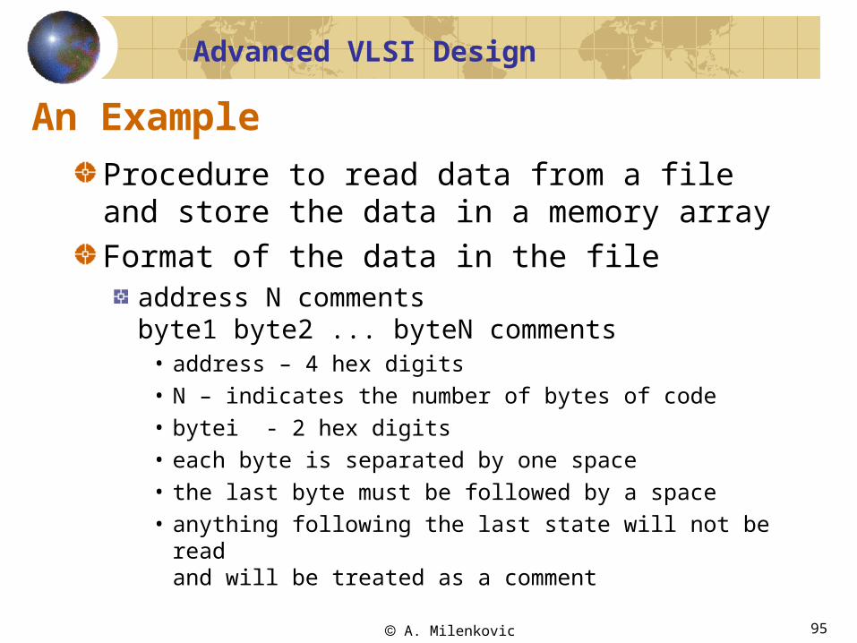
An Example
Procedure to read data from a file and store the data in a memory array
Format of the data in the fileaddress N commentsbyte1 byte2 ... byteN comments
• address – 4 hex digits• N – indicates the number of bytes of code• bytei - 2 hex digits• each byte is separated by one space• the last byte must be followed by a space• anything following the last state will not be read
and will be treated as a comment
A. Milenkovic 96
Advanced VLSI Design
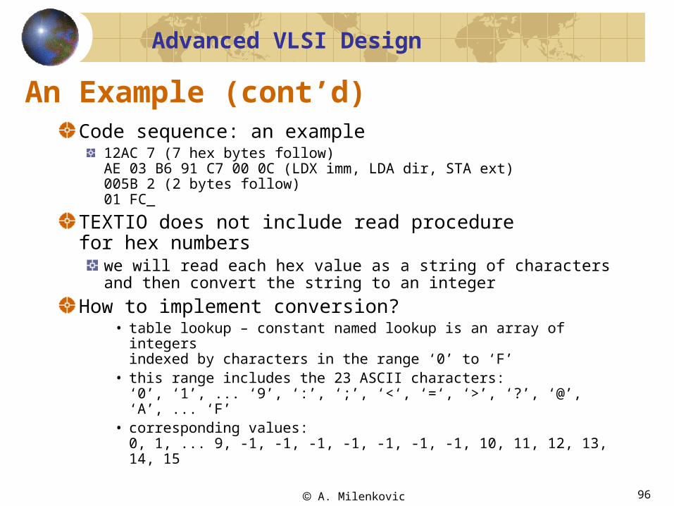
An Example (cont’d)Code sequence: an example
12AC 7 (7 hex bytes follow)AE 03 B6 91 C7 00 0C (LDX imm, LDA dir, STA ext)005B 2 (2 bytes follow)01 FC_
TEXTIO does not include read procedure for hex numbers
we will read each hex value as a string of charactersand then convert the string to an integer
How to implement conversion?• table lookup – constant named lookup is an array of integers
indexed by characters in the range ‘0’ to ‘F’• this range includes the 23 ASCII characters:
‘0’, ‘1’, ... ‘9’, ‘:’, ‘;’, ‘<‘, ‘=‘, ‘>’, ‘?’, ‘@’, ‘A’, ... ‘F’• corresponding values:
0, 1, ... 9, -1, -1, -1, -1, -1, -1, -1, 10, 11, 12, 13, 14, 15

A. Milenkovic 97
Advanced VLSI Design
VHDL Code to Fill Memory Array
A. Milenkovic 98
Advanced VLSI Design
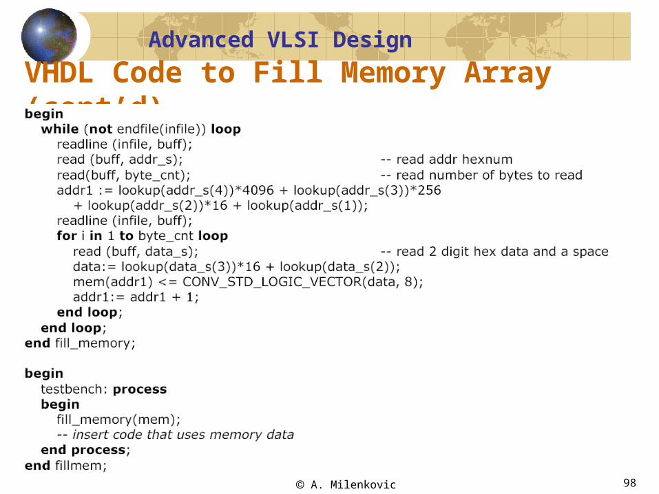
VHDL Code to Fill Memory Array (cont’d)
A. Milenkovic 99
Advanced VLSI Design
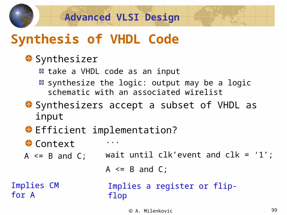
Synthesis of VHDL Code
Synthesizertake a VHDL code as an input
synthesize the logic: output may be a logic schematic with an associated wirelist
Synthesizers accept a subset of VHDL as input
Efficient implementation?
Context
A <= B and C;
...
wait until clk’event and clk = ‘1’;
A <= B and C;
Implies CM for A Implies a register or flip-flop
A. Milenkovic 100
Advanced VLSI Design
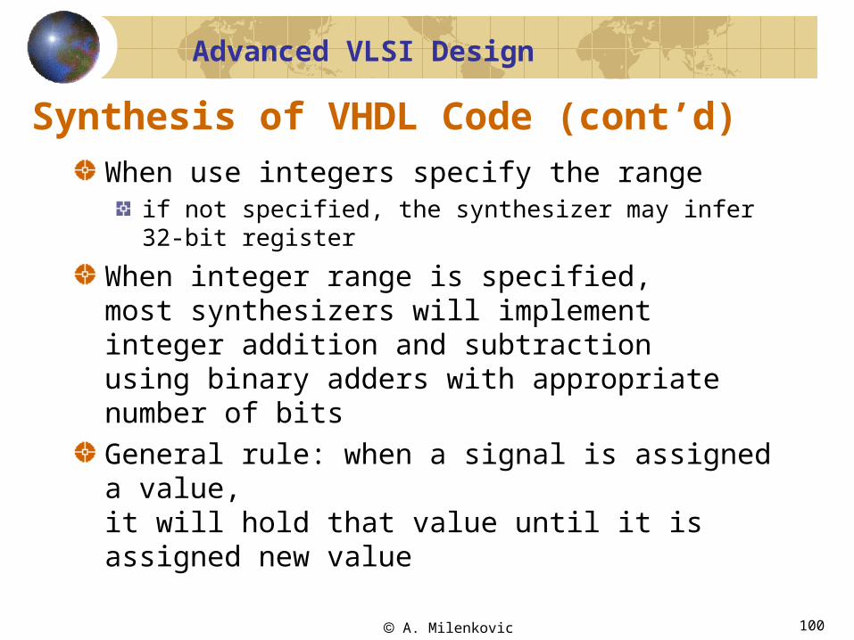
Synthesis of VHDL Code (cont’d)When use integers specify the range
if not specified, the synthesizer may infer 32-bit register
When integer range is specified,most synthesizers will implement integer addition and subtraction using binary adders with appropriate number of bits
General rule: when a signal is assigned a value,it will hold that value until it is assigned new value

A. Milenkovic 101
Advanced VLSI Design
Unintentional Latch Creation
What if a = 3?
The previous value of b should be held in the latch, so G should be 0 when a = 3.

A. Milenkovic 102
Advanced VLSI Design
If Statements
if A = ‘1’ then NextState <= 3;
end if;
What if A /= 1?
Retain the previous value for NextState?
Synthesizer might interpret this to mean that NextState is unknown!
if A = ‘1’ then NextState <= 3;
else NextState <= 2;
end if;

A. Milenkovic 103
Advanced VLSI Design
Synthesis of an If Statement
Synthesized code before optimization
A. Milenkovic 104
Advanced VLSI Design
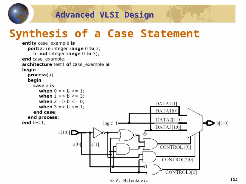
Synthesis of a Case Statement

A. Milenkovic 105
Advanced VLSI Design
Case Statement: Before and After Optimization
A. Milenkovic 106
Advanced VLSI Design
Standard VHDL Synthesis PackageEvery VHDL synthesis tool provides its own package of functions for operations commonly used in hardware modelsIEEE is developing a standard synthesis package,which includes functions for arithmetic operations on bit_vectors and std_logic vectors
numeric_bit package defines operations on bit_vectors• type unsigned is array (natural range<>) of bit;• type signed is array (natural range<>) of bit;
package include overloaded versions of arithmetic,relational, logical, and shifting operations, and conversion functionsnumeric_std package defines similar operations on std_logic vectors

A. Milenkovic 107
Advanced VLSI Design
Numeric_bit, Numeric_std
Overloaded operatorsUnary: abs, -
Arithmetic: +, -, *, /, rem, mod
Relational: >, <, >=, <=, =, /=
Logical: not, and, or, nand, nor, xor, xnor
Shifting: shift_left, shift_right, rotate_left, rotate_right,sll, srl, rol, ror

A. Milenkovic 108
Advanced VLSI Design
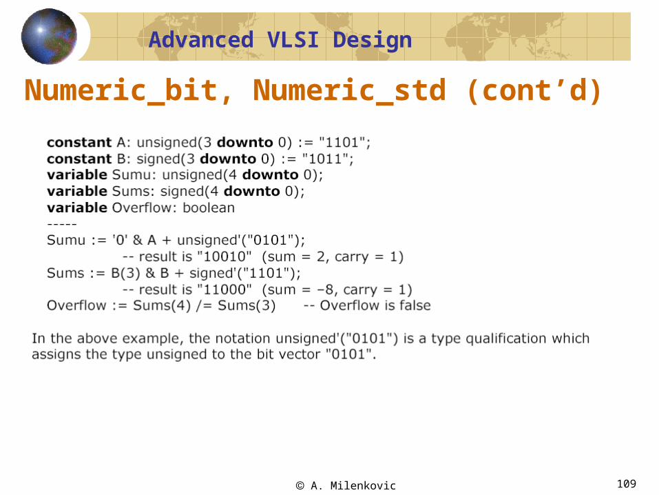
Numeric_bit, Numeric_std (cont’d)
A. Milenkovic 109
Advanced VLSI Design
Numeric_bit, Numeric_std (cont’d)

A. Milenkovic 110
Advanced VLSI Design
Synthesis Examples (1)
A. Milenkovic 111
Advanced VLSI Design
Synthesis Examples (2a)
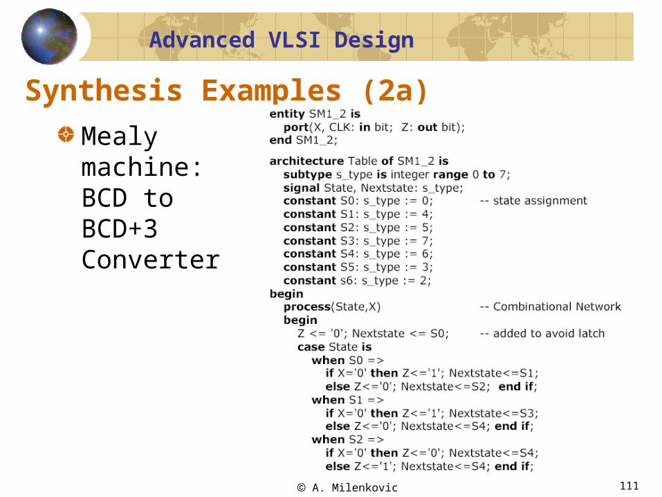
Mealy machine: BCD to BCD+3 Converter

A. Milenkovic 112
Advanced VLSI Design
Synthesis Examples (2b)
Mealy machine: BCD to BCD+3 Converter
A. Milenkovic 113
Advanced VLSI Design
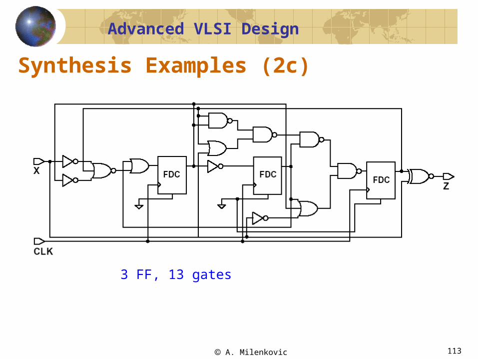
Synthesis Examples (2c)
3 FF, 13 gates

A. Milenkovic 114
Advanced VLSI Design
Writing Test BenchesMUX 16 to 1
16 data inputs
4 selection inputs
library IEEE;
use IEEE.std_logic_1164.all;
use IEEE.std_logic_unsigned.all;
entity SELECTOR is
port(
A: in std_logic_vector(15 downto 0);
SEL: in std_logic_vector(3 downto 0);
Y: out std_logic);
end SELECTOR;
architecture RTL of SELECTOR is
begin
Y <= A(conv_integer(SEL));
end RTL;
A. Milenkovic 115
Advanced VLSI Design
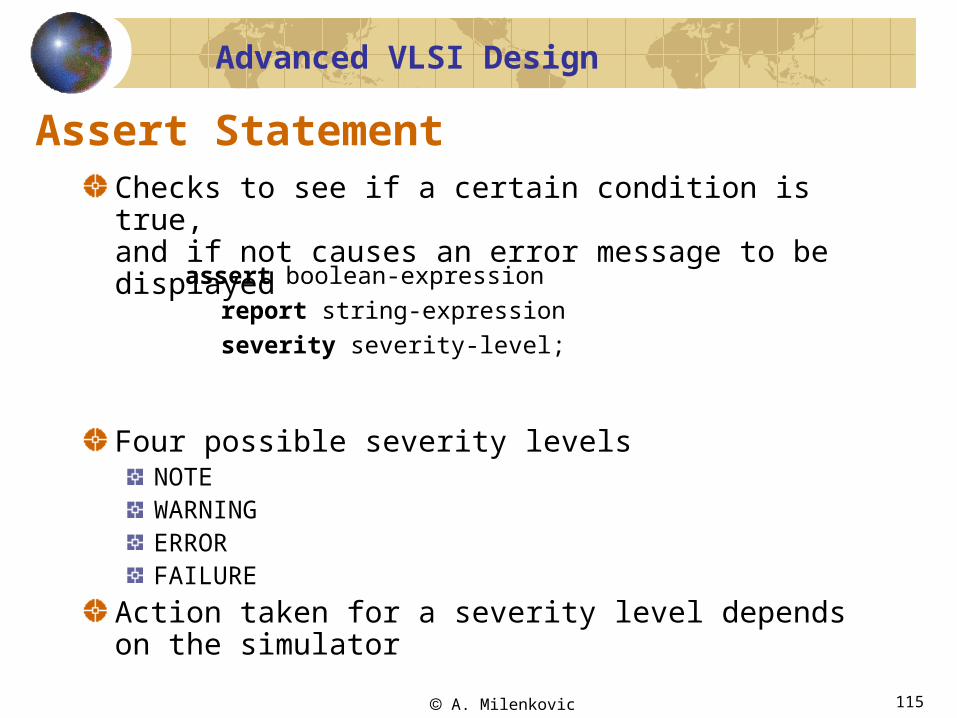
Assert StatementChecks to see if a certain condition is true,and if not causes an error message to be displayed
Four possible severity levelsNOTEWARNINGERRORFAILURE
Action taken for a severity level depends on the simulator
assert boolean-expression
report string-expression
severity severity-level;
A. Milenkovic 116
Advanced VLSI Design
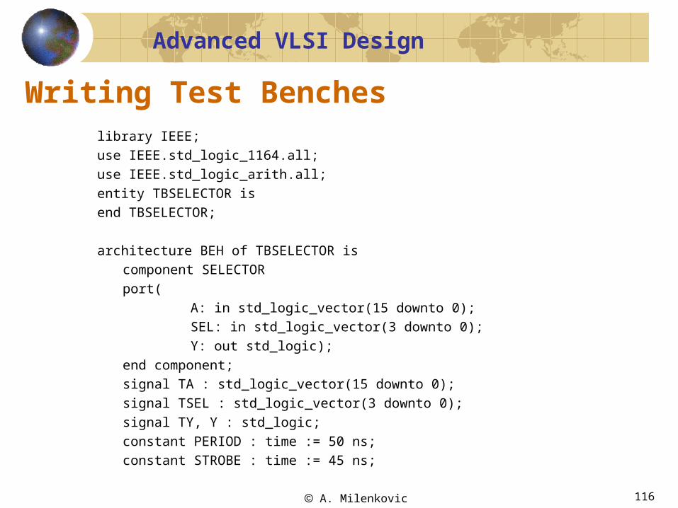
Writing Test Bencheslibrary IEEE;
use IEEE.std_logic_1164.all;
use IEEE.std_logic_arith.all;
entity TBSELECTOR is
end TBSELECTOR;
architecture BEH of TBSELECTOR is
component SELECTOR
port(
A: in std_logic_vector(15 downto 0);
SEL: in std_logic_vector(3 downto 0);
Y: out std_logic);
end component;
signal TA : std_logic_vector(15 downto 0);
signal TSEL : std_logic_vector(3 downto 0);
signal TY, Y : std_logic;
constant PERIOD : time := 50 ns;
constant STROBE : time := 45 ns;
A. Milenkovic 117
Advanced VLSI Design
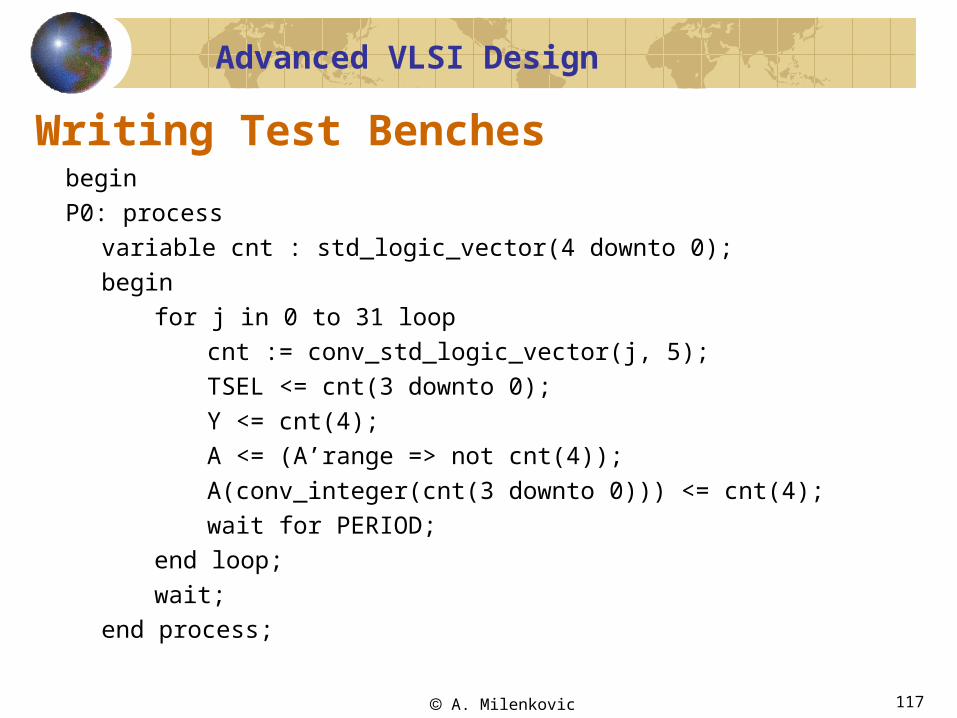
Writing Test Benchesbegin
P0: process
variable cnt : std_logic_vector(4 downto 0);
begin
for j in 0 to 31 loop
cnt := conv_std_logic_vector(j, 5);
TSEL <= cnt(3 downto 0);
Y <= cnt(4);
A <= (A’range => not cnt(4));
A(conv_integer(cnt(3 downto 0))) <= cnt(4);
wait for PERIOD;
end loop;
wait;
end process;

A. Milenkovic 118
Advanced VLSI Design
Writing Test Benchesbegin
check: process
variable err_cnt : integer := 0;
begin
wait for STROBE;
for j in 0 to 31 loop
assert FALSE report “comparing” severity NOTE;
if (Y /= TY) then
assert FALSE report “not compared” severity WARNING;
err_cnt := err_cnt + 1;
end if;
wait for PERIOD;
end loop;
assert (err_cnt = 0) report “test failed” severity ERROR;
assert (err_cnt /= 0) report “test passed” severity NOTE;
wait;
end process;
sel1: SELECTOR port map (A => TA, SEL = TSEL, Y => TY);
end BEH;

A. Milenkovic 119
Advanced VLSI Design
Things to RememberAttributes associated to signals
allow checking for setup, hold times, and other timing specifications
Attributes associated to arraysallow us to write procedures that do not depend on the manner in which arrays are indexed
Inertial and transport delaysallow modeling of different delay types that occur in real systems
Operator overloadingallow us to extend the definition of VHDL operators so that they can be used with different types of operands
A. Milenkovic 120
Advanced VLSI Design
Things to Remember (cont’d)Multivalued logic and the associated resolution functions
allow us to model tri-state buses, and systems where a signal is driven by more than one source
Genericsallow us to specify parameter values for a componentwhen the component is instantiated
Generate statementsefficient way to describe systems with iterative structure
TEXTIOconvenient way for file input/output