CP1122 UltraSIL Polymer-Housed VariSTAR - Cooper Industries
20
CERTIFIED TEST REPORT UltraSIL ™ Polymer-Housed VariSTAR ™ Type US, UH, and UX Station-Class Surge Arresters FILE REF: 235-103 CP1122 PAGE: 1 of 20 0112 • New Issues
Transcript of CP1122 UltraSIL Polymer-Housed VariSTAR - Cooper Industries

CERTIFIED TEST REPORT
UltraSIL™ Polymer-Housed
VariSTAR™ Type US, UH, and UX
Station-Class
Surge Arresters
FILE REF: 235-103
CP1122 PAGE: 1 of 20
0112 • New Issues
UltraSIL™ Polymer-Housed VariSTAR™ Type
US, UH AND UX Station-Class Surge Arresters
CERTIFICATION
Statements made and data shown are, to the best of our knowledge and belief,correct and within the usual limits of commercial testing practice.
Chuck Daley Michael M. Ramarge Staff Engineer Manager of Product Engineering - Arresters
FILE REF: 235-103
CP1122 PAGE: 2 of 20
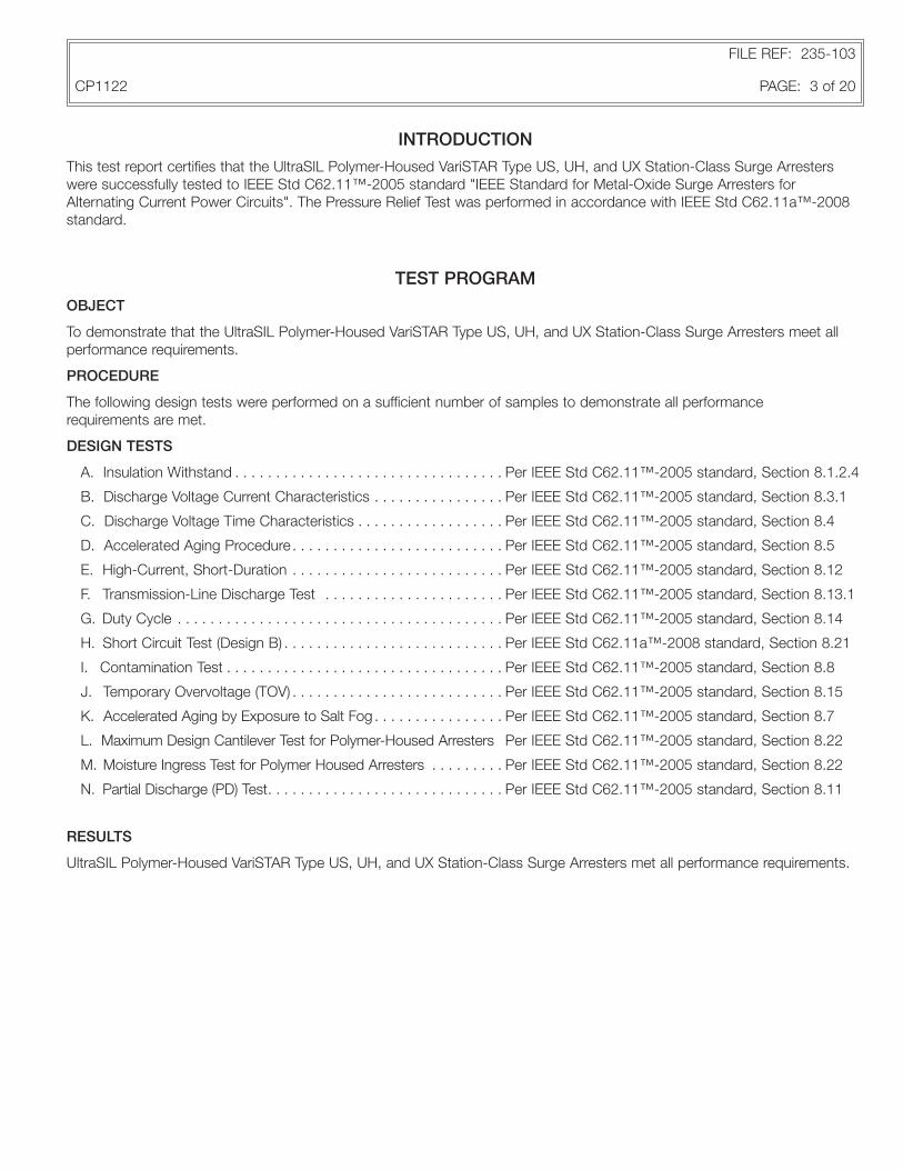
INTRODUCTION
This test report certifies that the UltraSIL Polymer-Housed VariSTAR Type US, UH, and UX Station-Class Surge Arresters were successfully tested to IEEE Std C62.11™-2005 standard "IEEE Standard for Metal-Oxide Surge Arresters for Alternating Current Power Circuits". The Pressure Relief Test was performed in accordance with IEEE Std C62.11a™-2008 standard.
TEST PROGRAM
OBJECT
To demonstrate that the UltraSIL Polymer-Housed VariSTAR Type US, UH, and UX Station-Class Surge Arresters meet all performance requirements.
PROCEDURE
The following design tests were performed on a sufficient number of samples to demonstrate all performance requirements are met.
DESIGN TESTS
A. Insulation Withstand . . . . . . . . . . . . . . . . . . . . . . . . . . . . . . . . . Per IEEE Std C62.11™-2005 standard, Section 8.1.2.4
B. Discharge Voltage Current Characteristics . . . . . . . . . . . . . . . . Per IEEE Std C62.11™-2005 standard, Section 8.3.1
C. Discharge Voltage Time Characteristics . . . . . . . . . . . . . . . . . . Per IEEE Std C62.11™-2005 standard, Section 8.4
D. Accelerated Aging Procedure . . . . . . . . . . . . . . . . . . . . . . . . . . Per IEEE Std C62.11™-2005 standard, Section 8.5
E. High-Current, Short-Duration . . . . . . . . . . . . . . . . . . . . . . . . . . Per IEEE Std C62.11™-2005 standard, Section 8.12
F. Transmission-Line Discharge Test . . . . . . . . . . . . . . . . . . . . . . Per IEEE Std C62.11™-2005 standard, Section 8.13.1
G. Duty Cycle . . . . . . . . . . . . . . . . . . . . . . . . . . . . . . . . . . . . . . . . Per IEEE Std C62.11™-2005 standard, Section 8.14
H. Short Circuit Test (Design B) . . . . . . . . . . . . . . . . . . . . . . . . . . . Per IEEE Std C62.11a™-2008 standard, Section 8.21
I. Contamination Test . . . . . . . . . . . . . . . . . . . . . . . . . . . . . . . . . . Per IEEE Std C62.11™-2005 standard, Section 8.8
J. Temporary Overvoltage (TOV) . . . . . . . . . . . . . . . . . . . . . . . . . . Per IEEE Std C62.11™-2005 standard, Section 8.15
K. Accelerated Aging by Exposure to Salt Fog . . . . . . . . . . . . . . . . Per IEEE Std C62.11™-2005 standard, Section 8.7
L. Maximum Design Cantilever Test for Polymer-Housed Arresters Per IEEE Std C62.11™-2005 standard, Section 8.22
M. Moisture Ingress Test for Polymer Housed Arresters . . . . . . . . . Per IEEE Std C62.11™-2005 standard, Section 8.22
N. Partial Discharge (PD) Test. . . . . . . . . . . . . . . . . . . . . . . . . . . . . Per IEEE Std C62.11™-2005 standard, Section 8.11
RESULTS
UltraSIL Polymer-Housed VariSTAR Type US, UH, and UX Station-Class Surge Arresters met all performance requirements.
FILE REF: 235-103
CP1122 PAGE: 3 of 20

TEST AINSULATION WITHSTAND
OBJECTTo verify that the assembled insulating members of the VariSTAR Type US, UH, and UX Station-Class Surge Arresters with-stand impulse and power frequency voltage tests in accordance with IEEE Std C62.11™-2005 standard.
PROCEDUREArresters rated 3-48 kV:• New, clean arresters of each rating, with internal parts rendered inoperative, were subjected to positive and negative 1.2 x
50 µs voltage impulses which exceeded the minimum values in IEEE Std C62.11™-2005 standard Table 4.• These samples were also subjected to both wet and dry 60 Hertz withstand voltages which exceeded the minimum val-
ues in IEEE Std C62.11™-2005 standard, Table 4.
Arresters rated ≥ 54 kV:• For each arrester rating the maximum 8 x 20, 20 kA discharge voltage was determined. This value was multiplied by a
factor of 1.42. This calculated value established the minimum 1.2 x 50 µs impulse withstand level.• New, clean arrester samples of each rating, with internal parts removed, were subjected to positive and negative 1.2 x 50
µs voltage impulses which exceeded the minimum withstand levels as calculated above.• For each arrester rating, the maximum switching impulse discharge voltage was determined. This value was multiplied by
a factor of 0.82. This calculated value established the minimum 10 second, wet 60 Hz withstand voltage in rms volts for each arrester.
• Arrester samples of each rating having the internal parts removed, were wetted and subjected to 10 seconds of 60 Hz rms voltages exceeding the minimum withstand voltages as calculated above.
RESULTSNone of the samples flashed over during any of the above tests in accordance with the insulation withstand requirements of IEEE Std C62.11™-2005 standard. Table 1 shows the insulation withstand voltages for VariSTAR Type US, UH, and UX Station-Class Surge Arresters.
TEST B DISCHARGE VOLTAGE CURRENT CHARACTERISTICS
OBJECTTo determine the maximum discharge voltage characteristics of the VariSTAR Type US, UH, and UX Station-Class Surge Arresters at 1.5, 3, 5, 10, 20 and 40 kA crest in accordance with IEEE Std C62.11™-2005 standard.
PROCEDURE• Sample arresters were impulsed using an 8 x 20 µs wave shape at 1.5, 3, 5, 10, 20 and 40 kA crest.• The discharge voltage crest was measured.
RESULTSCharts 3, 4, and 5 show the maximum 8 x 20 discharge voltages for the VariSTAR Type US, UH, and UX Station-Class Surge Arresters.
FILE REF: 235-103
CP1122 PAGE: 4 of 20

TEST C DISCHARGE VOLTAGE TIME CHARACTERISTICS
OBJECTTo obtain the front-of-wave and switching impulse protective levels of the VariSTAR Type US, UH, and UX Station-Class Surge Arresters in accordance with IEEE Std C62.11™-2005 standard.
PROCEDUREFront-of-Wave Protective Level: • A current of 10 kA was used to determine the front-of-wave protective level. • The arresters were impulsed using front times of 8 µs, 2 µs and 1 µs. • The maximum discharge voltage and the time to voltage crest were measured. • The voltage/time measurements were plotted on linear voltage versus log time paper and the maximum voltage at
0.5 µs was determined.
Switching Impulse Protective Level:• Currents of 500 and 1000 Amperes crest were used to determine the switching impulse protective level. • The arresters were impulsed with switching impulse current waves having a time to actual crest of 45 to 60 µs. • The discharge voltage crest was measured.
RESULTS Tables 3, 4, and 5 show the front-of-wave and switching impulse protective levels for the VariSTAR Type US, UH, and UX Station-Class Surge Arresters.
TEST D ACCELERATED AGING PROCEDURE
OBJECTTo verify the KC and KR ratios of the VariSTAR Type US, UH, and UX Station-Class Surge Arresters in accordance with IEEE Std C62.11™-2005 standard. KC = MCOV Ratio KR = Duty Cycle RatioThese ratios were determined to calculate the test values of MCOV and duty cycle voltages used during testing.
PROCEDURE• Samples were placed in an oven at 115 °C and energized at MCOV for 1,000 hours. • The watts loss was measured at the MCOV and duty cycle voltage levels within two to five hours after the start of the test.• The watts loss was remeasured at 1,000 hours at MCOV and duty cycle voltage levels. Watts Loss @, 1,000 Hrs @ MCOV• KC =
Watts Loss @ 2-5 Hrs @ MCOV
Watts Loss @1,000 Hrs @ Rated Voltage • KR = Watts Loss @ 2-5 Hrs @ Rated Voltage
If KC and KR, - 1, then KC, and KR are equal to 1.
RESULTSKC and KR = 1.
FILE REF: 235-103
CP1122 PAGE: 5 of 20

TEST E HIGH-CURRENT, SHORT-DURATION
OBJECTTo demonstrate that the VariSTAR Type US, UH, and UX Station-Class Surge Arresters meet the high-current, short-duration requirements in accordance with IEEE Std C62.11™-2005 standard.
Kw = Watts Loss Ratio
PROCEDURE• Three prorated equivalent thermal sections were used for this test.• Each sample was impulsed with a 100 kA crest current with a wave shape of 4 x 10 µs. This exceeded the required crest
current of 65 kA.• The samples were allowed to cool to ambient temperature.• Each sample was impulsed a second time.• Immediately following the second impulse, the samples were energized at the thermal recovery voltage per IEEE Std
C62.11™-2005 standard (MCOV x KW x KC) for 30 minutes to verify thermal recovery.• The samples were inspected after testing to verify that there was no physical damage.• Kw = Voltage at max watts/MCOV
RESULTSVariSTAR Type US, UH, and UX Station-Class Surge Arresters met the high-current, short-duration requirements of two impulses, thermal recovery, and no physical damage.
TEST F TRANSMISSION-LINE DISCHARGE TEST
OBJECTTo demonstrate that the VariSTAR Type US, UH, and UX Station-Class Surge Arresters meet the transmission-line discharge test in accordance with IEEE Std C62.11™-2005 standard.
PROCEDURE• Three prorated equivalent thermal sections were used for this test.• Each sample was impulsed with a 10 kA crest, 8 x 20 µs wave and the discharge voltage was measured.• Each sample was subjected to three groups of six consecutive Transmission-Line Discharge (TLD) operations timed to
occur 50 to 60 seconds apart. The TLD operations were as defined in IEEE Std C62.11™-2005 standard.• The samples were permitted to cool after each group of six impulses.• After the 18th impulse the samples were heated to 60 degrees centigrade and allowed to thermally stabilize.• Within two minutes upon removal from the oven, two additional TLD impulses were applied 50 to 60 seconds apart.• Within one minute the appropriate 60 Hz voltage was applied and the watts loss was monitored for a minimum of 30
minutes to verify thermal recovery.• Each sample was subjected to a final 10 kA crest, 8 x 20 µs impulse wave and the discharge voltage measured. The
discharge voltage was compared to the discharge voltage taken prior to duty cycle to make sure that it did not vary by more than ±10%.
• The samples were inspected after testing to assure that no physical damage occurred.
RESULTSVariSTAR Type US, UH, and UX Station-Class Surge Arresters met the Transmission-Line Discharge test requirements of 20 impulses, <10% change in discharge voltage, and no physical damage.
FILE REF: 235-103
CP1122 PAGE: 6 of 20

TEST G DUTY CYCLE
OBJECT To demonstrate that the VariSTAR Type US, UH, and UX Station-Class Surge Arresters meet the duty cycle requirements in accordance with IEEE Std C62.11™-2005 standard.
PROCEDURE• Three prorated equivalent thermal sections were used for this test. • Each sample was impulsed with 10 kA crest, 8 x 20 µs wave and the discharge voltage measured. • Each sample was energized at KR times the duty cycle voltage (KR = 1), for the duration of time needed to allow 20
impulses. • Each sample was impulsed with 10 kA crest surges of 8 x 20 µs wave shape. • Each impulse occurred at approximately 60° before the crest on the power frequency wave. • Each sample was impulsed once every 50 to 60 seconds for 20 consecutive impulses. • After the 20th impulse, the samples were de-energized and placed into an oven until they stabilized at 60 °C. • Each sample was removed from the oven and immediately energized at KC times the MCOV (KC = 1) and impulsed twice
more with a 10 kA crest, 8/20 µs wave within one minute. • Samples remained energized at the thermal recovery voltage per IEEE Std C62.11™-2005 standard (MCOV x KW x KC)
for 30 minutes minimum to verify thermal recovery. • Each sample was then impulsed with a 10 kA crest, 8 x 20 µs wave and the discharge voltage measured. The
discharge voltage was compared to the discharge voltage taken prior to duty cycle to make sure that it did not vary by more than ±10%.
• The samples were inspected after testing to assure that no physical damage occurred.
RESULTS VariSTAR Type US, UH, and UX Station-Class Surge Arresters met the duty cycle test requirements of 22 impulses, thermal recovery, <10% change in discharge voltage, and no physical damage.
FILE REF: 235-103
CP1122 PAGE: 7 of 20

TEST H SHORT CIRCUIT TEST
(DESIGN B)OBJECT To verify that the pressure-relief capability of VariSTAR Type US, UH, and UX Station-Class Surge Arresters meet the requirements in accordance with IEEE Std C62.11a™-2008 standard.
PROCEDURE• 60kV rated samples were used in the testing for the US design and 72 kV rated samples were used for the UH & UX
designs, which represent the highest voltage rating in a single unit housing. • The arrester samples were mounted to simulate service conditions as specified by IEEE Std C62.11a™-2008 standard.
High-Current Pressure-Relief Testing:• Samples were prefailed by power frequency overvoltage.• The test circuit was adjusted to produce a 60 Hz, 65 kA (rms) current for a minimum of 0.2 seconds.• The above noted current was initiated within 5° of the applied 60 Hz voltage zero.• The arresters were monitored to assure venting occurred without violent shattering.
Low-Current Pressure-Relief Testing:• Samples were prefailed by power frequency overvoltage.• The test circuit was adjusted to produce a 60 Hz current of 600 A determined by the average for the duration of the
current flow.• The current duration lasted until the arrester vented up to a maximum of 1 second or until venting occurs.
RESULTSVariSTAR Type US, UH, and UX Station-Class Surge Arresters passed the described high and low-current pressure-relief tests based on oscillograph recordings showing test current magnitude and duration, from the evidence of the time at which the venting occurred, and from the confinement of all components of the arrester within the specified enclosures.
TEST I CONTAMINATION TEST
OBJECT To demonstrate the ability of the VariSTAR Type US, UH, and UX Station-Class Surge Arresters to withstand the electrical stresses caused by contamination on the housing, in accordance with IEEE Std C62.11™-2005 standard.
PROCEDURE• 240 kV samples were used in this test.• Arrester samples were energized for a minimum of one hour at MCOV. • The watts loss at MCOV was measured at the end of the hour.• The samples were de-energized. Within 13 minutes, a 400-500 Ωm slurry was applied to the housing heavily enough to
form drops on the skirts. • The samples were energized at the MCOV voltage. • The watts loss was measured after 15 minutes. • The samples were de-energized again and another slurry application was performed. • The samples were energized at MCOV for 30 minute intervals and the watts loss was monitored to verify decreasing levels
towards the original measurement. • Once the samples were cleaned and dried, they were inspected for internal damage using partial discharge measurements
at MCOV.
RESULTS VariSTAR Type US, UH, and UX Station-Class Surge Arrester samples passed the test by having stabilized lower watts loss over time, by not flashing over and by not having any internal physical damage in accordance with IEEE Std C62.11™-2005 standard.
FILE REF: 235-103
CP1122 PAGE: 8 of 20

TEST J TEMPORARY OVERVOLTAGE (TOV)
OBJECT To verify what levels of 60 cycle temporary overvoltage the VariSTAR Type US, UH, and UX Station-Class Surge Arresters survive in accordance with IEEE Std C62.11™-2005 standard.
PROCEDURE• Prorated equivalent thermal sections were used for this test. • Each sample was impulsed with a 10 kA crest, 8 x 20 µs wave and the discharge voltage measured. • Samples were preheated to 60 °C.• Each sample was removed from the oven and immediately energized at the overvoltage. • The overvoltage was removed before sample failure. • Within 1 second, each sample was energized at the thermal recovery voltage per IEEE Std C62.11™-2005 standard
(MCOV x KW x Kc) for 30 minutes. Sample current and temperature were monitored for thermal runaway. • Each sample was impulsed with a 10 kA crest, 8 x 20 µs wave and the discharge voltage measured. The discharge
voltage was compared to the discharge voltage taken prior to the Temporary Overvoltage testing to make sure that it did not vary by more than 10%.
• The samples were inspected after testing to assure that no physical damage occurred. • Temporary overvoltage test points were plotted. • The above test procedures were repeated with "prior duty" energy applied to the arrester before the TOV is applied. • The "prior duty" energy applied to the arrester before the TOV was the energy generated in two transmission line
discharges. • The "prior duty" energy applied to Type US (3-108 kV) arresters was 3.9 kJ/kV of MCOV and 6.2 kJ/kV of MCOV for 120-
240 kV Type US arresters. For Type UH (3-108 kV) arresters, the energy was 6.2 kJ/kV of MCOV and 10 kJ/kV of MCOV for 120-240 kV Type UH arresters. For Type UX arresters, the energy was 10 kJ/kV of MCOV.
RESULTS Graph 1 and Table 6 show the performance results
TEST KACCELERATED AGING BY EXPOSURE TO SALT FOG
OBJECTThe purpose of this test is to demonstrate the ability of the VariSTAR Type US, UH, and UX Station-Class Surge Arresters to withstand electrical stresses on the arrester housing caused by exposure to salt fog, in accordance with IEEE Std C62.11™-2005 standard.
PROCEDURE• Complete 72 kV Samples were used for this test.• The Reference Voltage at specified Reference Current and Partial Discharge at 1.05 x MCOV were recorded.• Samples were mounted vertically in a moisture-sealed corrosion-proof chamber.• The fog should continually fill the chamber.• The samples were energized at MCOV for time duration of 1,000 hours.• The samples were inspected after testing to assure no physical damage occurred.• The Reference Voltage at specified Reference Current and Partial Discharge at 1.05 x MCOV were recorded.
RESULTSVariSTAR Type US, UH, and UX Station-Class Surge Arresters met the Accelerated Aging by Exposure to Salt Fog require-ments of no tracking occurring, erosion did not penetrate through housing material, sheds and housing were not punctured, reference voltage did not decrease by more than 5% from initial measurements, and partial discharge did not exceed 10pc before and after testing.
FILE REF: 235-103
CP1122 PAGE: 9 of 20

TEST LMAXIMUM DESIGN CANTILEVER TEST FOR POLYMER HOUSED ARRESTERS
OBJECTTo evaluate the Maximum Design Cantilever Load (MDCL-Static) specified by the manufacturer for polymer housed arresters in accordance with IEEE Std C62.11™-2005 standard.
PROCEDURE• The sample consisted of the longest mechanical unit of the design family consisting of an end casting and top terminal
assembly.• Power loss at 80-100% MCOV (noting ambient temperature) and Nominal Discharge Current at 1.5 kA measurements are
recorded.• Terminal torque levels of 100 ft-lbs were applied to samples using 20mm top studs and 150 ft-lbs for samples using 1.0"
top studs for time durations of 30s.• Thermomechanical Preconditioning.
- The sample is subject to the Maximum Design Cantilever Load with variations in load direction and temperature according to IEEE Std C62.11™-2005 standard, Figure 4.
- Maximum Design Cantilever Load is 6,000 in-lbs for Type US (3-108 kV); 8,000 in-Ibs for Type UH (3-108 kV) and US (120-240 kV); 14,000 in-Ibs for Type UX (3-108 kV) and UH (120-240 kV) arresters.
- Each temperature shall be maintained for a minimum of 16 hours and no longer than 24 hours.- The sample is subject to 0° load direction at 60 ° ±3 °C.- The sample is subject to 180° load direction at -25 ° ±3 °C.- The sample is subject to 270° load direction at 45 ° ±3 °C.- The sample is subject to 90° load direction at -40 ° ±3 °C.- The deflection at each direction shall be noted.
- The sample is then subjected to loads at each direction in ambient temperature for a period of 24 hrs per direction. The deflection at each direction shall be noted.
• Power loss at 80-100% MCOV (noting ambient temperature) and Nominal Discharge Current at 1.5 kA measurements are recorded.
RESULTSVariSTAR Type US, UH, and UX Station-Class Surge Arresters met Maximum Design Cantilever test requirements of the power loss and did not increase by more than 20% from the initial measurement. The residual voltage at 1.5 kA did not deviate more than 5% from the initial measurement. The oscillograms did not reveal any voltage or current breakdown, and partial discharge at 1.05 x MCOV did not exceed 10pC.
FILE REF: 235-103
CP1122 PAGE: 10 of 20
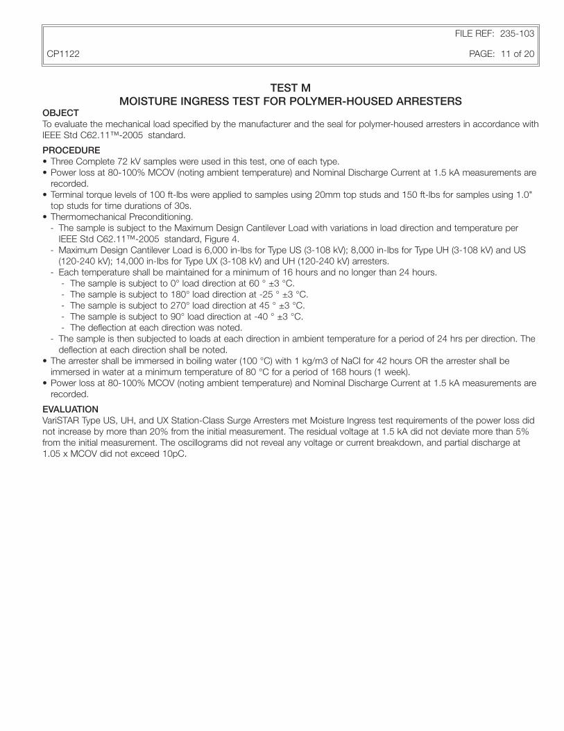
TEST MMOISTURE INGRESS TEST FOR POLYMER-HOUSED ARRESTERS
OBJECTTo evaluate the mechanical load specified by the manufacturer and the seal for polymer-housed arresters in accordance with IEEE Std C62.11™-2005 standard.
PROCEDURE• Three Complete 72 kV samples were used in this test, one of each type.• Power loss at 80-100% MCOV (noting ambient temperature) and Nominal Discharge Current at 1.5 kA measurements are
recorded.• Terminal torque levels of 100 ft-lbs were applied to samples using 20mm top studs and 150 ft-lbs for samples using 1.0"
top studs for time durations of 30s.• Thermomechanical Preconditioning.
- The sample is subject to the Maximum Design Cantilever Load with variations in load direction and temperature per IEEE Std C62.11™-2005 standard, Figure 4.
- Maximum Design Cantilever Load is 6,000 in-lbs for Type US (3-108 kV); 8,000 in-Ibs for Type UH (3-108 kV) and US (120-240 kV); 14,000 in-Ibs for Type UX (3-108 kV) and UH (120-240 kV) arresters.
- Each temperature shall be maintained for a minimum of 16 hours and no longer than 24 hours.- The sample is subject to 0° load direction at 60 ° ±3 °C.- The sample is subject to 180° load direction at -25 ° ±3 °C.- The sample is subject to 270° load direction at 45 ° ±3 °C.- The sample is subject to 90° load direction at -40 ° ±3 °C.- The deflection at each direction was noted.
- The sample is then subjected to loads at each direction in ambient temperature for a period of 24 hrs per direction. The deflection at each direction shall be noted.
• The arrester shall be immersed in boiling water (100 °C) with 1 kg/m3 of NaCl for 42 hours OR the arrester shall be immersed in water at a minimum temperature of 80 °C for a period of 168 hours (1 week).
• Power loss at 80-100% MCOV (noting ambient temperature) and Nominal Discharge Current at 1.5 kA measurements are recorded.
EVALUATIONVariSTAR Type US, UH, and UX Station-Class Surge Arresters met Moisture Ingress test requirements of the power loss did not increase by more than 20% from the initial measurement. The residual voltage at 1.5 kA did not deviate more than 5% from the initial measurement. The oscillograms did not reveal any voltage or current breakdown, and partial discharge at 1.05 x MCOV did not exceed 10pC.
FILE REF: 235-103
CP1122 PAGE: 11 of 20

TEST NPARTIAL DISCHARGE (PD) TEST
OBJECTThe purpose of this test is to verify that the VariSTAR Type US, UH, and UX Station-Class Surge Arresters do not generate unacceptable levels of partial discharge according to IEEE Std C62.11™-2005 standard.
PROCEDURE
• The samples were 240 kV arresters, one of each type.• The corrected Rated and MCOV voltages were calculated based on the correction factor of Vref measured/ Vref minimum.• The voltage was raised to rated voltage for 2 seconds, then lowered to 1.05 x corrected MCOV.• The partial discharge was measured at this level voltage.
EVALUATIONVariSTAR Type US, UH, and UX Station-Class Surge Arresters met Partial Discharge test requirements. Partial discharge at 1.05 x corrected MCOV did not exceed 10pC.
FILE REF: 235-103
CP1122 PAGE: 12 of 20

TABLE 1 Insulation Withstand Voltages - VariSTAR Type US, UH, and UX Station-Class Surge Arresters with Standard Creep Housings
FILE REF: 235-103
CP1122 PAGE: 13 of 20
Arrester Rating
(kV, rms)
Arrester MCOV
(kV, rms)
Creepage Distance (Inches)
Insulation Withstand Voltages
1.2/50 Impulse (kV, Crest)
Switching Surge Impulse
(kV, Crest)
60 Hz, dry 60 Seconds
(kV, rms)
60 Hz, wet 10 Seconds
(kV, rms)
US UH UX US UH UX US UH UX US UH UX US UH UX
3 2.55 30.7 30.7 30.7 115 119 126 N/A N/A N/A 80 77 82 64 63 60
6 5.1 38.4 38.4 38.4 134 137 138 N/A N/A N/A 94 90 90 75 75 71
9 7.65 38.4 38.4 38.4 134 137 138 N/A N/A N/A 94 90 90 75 75 71
10 8.4 38.4 38.4 38.4 134 137 138 N/A N/A N/A 94 90 90 75 75 71
12 10.2 46.1 46.1 46.1 155 158 159 N/A N/A N/A 109 104 104 88 88 84
15 12.7 46.1 46.1 46.1 155 158 159 N/A N/A N/A 109 104 104 88 88 84
18 15.3 53.7 53.7 53.7 176 178 179 N/A N/A N/A 123 118 117 101 101 97
21 17.0 53.7 53.7 53.7 176 178 179 N/A N/A N/A 123 118 117 101 101 97
24 19.5 61.4 61.4 61.4 201 201 206 N/A N/A N/A 140 140 135 113 113 116
27 22.0 61.4 61.4 61.4 201 201 206 N/A N/A N/A 140 140 135 113 113 116
30 24.4 69.1 69.1 69.1 217 218 220 N/A N/A N/A 151 146 144 126 128 123
33 27.5 69.1 69.1 69.1 217 218 220 N/A N/A N/A 151 146 144 126 128 123
36 29.0 69.1 69.1 69.1 217 218 220 N/A N/A N/A 151 146 144 126 128 123
39 31.5 84.4 84.4 84.4 252 258 262 N/A N/A N/A 172 166 168 152 156 154
42 34.0 84.4 84.4 84.4 252 258 262 N/A N/A N/A 172 166 168 152 156 154
45 36.5 92.1 92.1 92.1 275 279 281 N/A N/A N/A 188 188 184 162 167 162
48 39.0 99.8 99.8 99.8 294 298 300 N/A N/A N/A 201 201 202 173 186 176
54 42.0 99.8 99.8 99.8 294 298 300 N/A N/A N/A 201 201 202 173 186 176
60 48.0 107.5 107.5 107.5 316 319 321 N/A N/A N/A 212 215 211 187 192 188
66 53.0 138.2 115.2 115.2 434 340 342 N/A N/A N/A 302 230 224 252 206 201
72 57.0 138.2 122.8 122.8 434 361 364 N/A N/A N/A 302 246 237 252 213 210
78 62.0 153.5 153.5 153.5 469 476 482 N/A N/A N/A 323 312 312 278 284 277
84 68.0 168.9 168.9 168.9 504 516 524 N/A N/A N/A 344 332 336 304 312 308
90 72.0 176.6 176.6 176.6 527 537 543 N/A N/A N/A 360 354 352 314 323 316
96 76.0 184.3 184.3 184.3 550 558 562 N/A N/A N/A 376 376 368 324 334 324
108 84.0 199.6 199.6 199.6 588 596 600 N/A N/A N/A 402 402 404 346 372 352
120 98.0 215 215 - 638 642 - N/A N/A - 430 422 - 384 376 -
132 106 230.3 230.3 - 680 684 - N/A N/A - 460 448 - 412 402 -
138 111 245.7 245.7 - 722 728 - N/A N/A - 492 474 - 426 420 -
144 115 245.7 245.7 - 722 728 - N/A N/A - 492 474 - 426 420 -
162 130 307.1 307.1 - 915 921 - N/A N/A - 617 615 - 564 540 -
168 131 314.8 314.8 - 936 942 - N/A N/A - 631 624 - 570 552 -
172 140 322.4 322.4 - 957 963 - N/A N/A - 646 637 - 584 565 -
180 144 330.1 330.1 - 978 985 - 972 1029 - 662 650 - 591 574 -
192 152 337.8 337.8 - 999 1006 - 994 1052 - 677 663 - 605 587 -
198 160 353.2 353.2 - 1041 1049 - 1040 1083 - 707 685 - 618 608 -
204 165 360.8 360.8 - 1062 1070 - 1062 1106 - 722 698 - 632 621 -
216 174 406.9 406.9 - 1213 1221 - 1197 1296 - 818 817 - 750 716 -
228 180 422.2 422.2 - 1255 1263 - 1247 1320 - 846 835 - 762 740 -
240 190 429.9 429.9 - 1276 1284 - 1272 1332 - 860 844 - 768 752 -

TABLE 2Dimensions, Clearance Requirements, and Weights - VariSTAR Type US, UH, and UX Station-Class Surge Arresters with Standard Creep Housings
FILE REF: 235-103
CP1122 PAGE: 14 of 20
* Temporary Overvoltage with Prior Duty.** Based on a 10 kA current impulse that results in a discharge voltage cresting in 0.5 μs*** Contact manufacturer for alternate electrical builds.**** 45-60 μs rise time for a 500 A peak current surge
Arrester Rating
(kV, rms)
Arrester MCOV
(kV, rms)
Figure 8 Dim. "A" (Inches)
Figure 5 Dim. "B" Minimum Phase-to-Ground
Clearances (inches)*
Figure 5 Dim. "C" Minimum Phase-to-Phase
Clearances (inches)*Figure 8 Dim. "D"
(inches)Weight (lbs.)
US UH UX US UH UX US UH UX US UH UX US UH UX
3 2.55 8.2 8.2 8.2 5.5 5.5 5.5 10 10 10 5.13 5.49 5.93 12.2 14 15.5
6 5.1 9.7 9.7 9.7 5.5 5.5 5.5 10 10 10 5.13 5.49 5.93 13.2 15.5 17.7
9 7.65 9.7 9.7 9.7 5.9 5.6 5.6 10.4 10.1 10.1 5.13 5.49 5.93 13.2 15.5 17.7
10 8.4 9.7 9.7 9.7 6.1 5.8 5.7 10.6 10.3 10.2 5.13 5.49 5.93 13.2 15.5 17.7
12 10.2 11.3 11.3 11.3 6.6 6.2 6 11.1 10.7 10.5 5.13 5.49 5.93 14.3 16.9 19.7
15 12.7 11.3 11.3 11.3 7.5 6.9 6.6 12 11.4 11.1 5.13 5.49 5.93 14.3 16.9 19.7
18 15.3 12.8 12.8 12.8 8.6 7.8 7.4 13.1 12.3 11.9 5.13 5.49 5.93 14.7 17.3 20.2
21 17.0 12.8 12.8 12.8 8.6 7.8 7.4 13.1 12.3 11.9 5.13 5.49 5.93 14.7 17.3 20.2
24 19.5 14.4 14.4 14.4 9.5 8.5 8 14 13 12.5 5.13 5.49 5.93 15.5 18.6 22
27 22.0 14.4 14.4 14.4 10.5 9.4 8.8 15 13.9 13.3 5.13 5.49 5.93 15.5 18.6 22
30 24.4 16 16 16 11.5 10.2 9.6 16 14.7 14.1 5.13 5.49 5.93 16.3 19.6 23.4
33 27.5 16 16 16 12.7 11.3 10.6 17.2 15.8 15.1 5.13 5.49 5.93 16.3 19.6 23.4
36 29.0 16 16 16 13.3 11.8 11.1 17.8 16.3 15.6 5.13 5.49 5.93 16.3 19.6 23.4
39 31.5 19.1 19.1 19.1 14.3 12.7 11.9 18.8 17.2 16.4 5.13 5.49 5.93 17.9 21.7 26.4
42 34.0 19.1 19.1 19.1 15.2 13.5 12.7 19.7 18 17.2 5.13 5.49 5.93 17.9 21.7 26.4
45 36.5 20.6 20.6 20.6 16.2 14.4 13.5 20.7 18.9 18 5.13 5.49 5.93 18.8 23 28.3
48 39.0 22.2 22.2 22.2 17.2 15.3 14.3 21.7 19.8 18.8 5.13 5.49 5.93 19.9 24.4 30.4
54 42.0 22.2 22.2 22.2 18.4 16.3 15.2 22.9 20.8 19.7 5.13 5.49 5.93 19.9 24.4 30.4
60 48.0 23.7 23.7 23.7 20.8 18.4 17.2 25.3 22.9 21.7 5.13 5.49 5.93 20.8 25.7 32.2
66 53.0 30 25.3 25.3 22.7 20.1 18.7 27.2 24.6 23.2 5.13 5.49 5.93 23.9 29.2 37.5
72 57.0 30 26.8 26.8 24.3 21.5 20 28.8 26 24.5 5.13 5.49 5.93 23.9 30.5 39.4
78 62.0 33.2 33.2 33.2 26.3 23.2 21.6 30.8 27.7 26.1 5.13 5.49 5.93 25.4 31.6 40.2
84 68.0 36.3 36.3 36.3 28.7 25.3 23.5 33.2 29.8 28 5.13 5.49 5.93 26.9 33.7 43.2
90 70.0 37.8 37.8 37.8 30.2 26.6 24.8 34.7 31.1 29.3 5.13 5.49 5.93 27.8 35 45.1
96 76.0 39.3 39.3 39.3 31.8 28 26.1 36.3 32.5 30.6 5.13 5.49 5.93 28.8 36.3 46.9
108 84.0 42.5 42.5 42.5 35 30.8 28.7 39.5 35.3 33.2 5.13 5.49 5.93 31 39.2 51.2
120 98.0 45.6 45.6 - 35.6 33.1 - 40.1 37.6 - 5.49 5.93 - 41.8 54.9 -
132 106 48.7 48.7 - 46.9 44.2 - 59.9 57.2 - 5.49 5.93 - 48.7 65.4 -
138 111 51.8 51.8 - 48.6 45.8 - 61.6 58.8 - 5.49 5.93 - 51.2 69 -
144 115 51.8 51.8 - 50 47.1 - 63 60.1 - 5.49 5.93 - 51.2 69 -
162 130 68.3 68.3 - 55.2 51.8 - 68.2 64.8 - 5.49 5.93 - 64.6 83.1 -
168 131 69.8 69.8 - 55.5 52.2 - 68.5 65.2 - 5.49 5.93 - 65.9 84.9 -
172 140 71.4 71.4 - 58.6 55 - 71.6 68 - 5.49 5.93 - 69.4 90.2 -
180 144 72.9 72.9 - 60 56.3 - 73 69.3 - 5.49 5.93 - 70.6 92 -
192 152 74.5 74.5 - 62.7 58.9 - 75.7 71.9 - 5.49 5.93 - 74.1 97.3 -
198 160 77.6 77.6 - 65.5 61.4 - 78.5 74.4 - 5.49 5.93 - 76.7 101 -
204 165 79.2 79.2 - 67.2 63 - 80.2 76 - 5.49 5.93 - 80.1 106.3 -
216 174 88.6 88.6 - 70.3 65.9 - 83.3 78.9 - 5.49 5.93 - 79.4 103.8 -
228 180 91.7 91.7 - 73.1 68.5 - 86.1 81.5 - 5.49 5.93 - 82 107.6 -
240 190 93.2 93.2 - 75.8 71 - 88.8 84 - 5.49 5.93 - 83.3 109.4 -
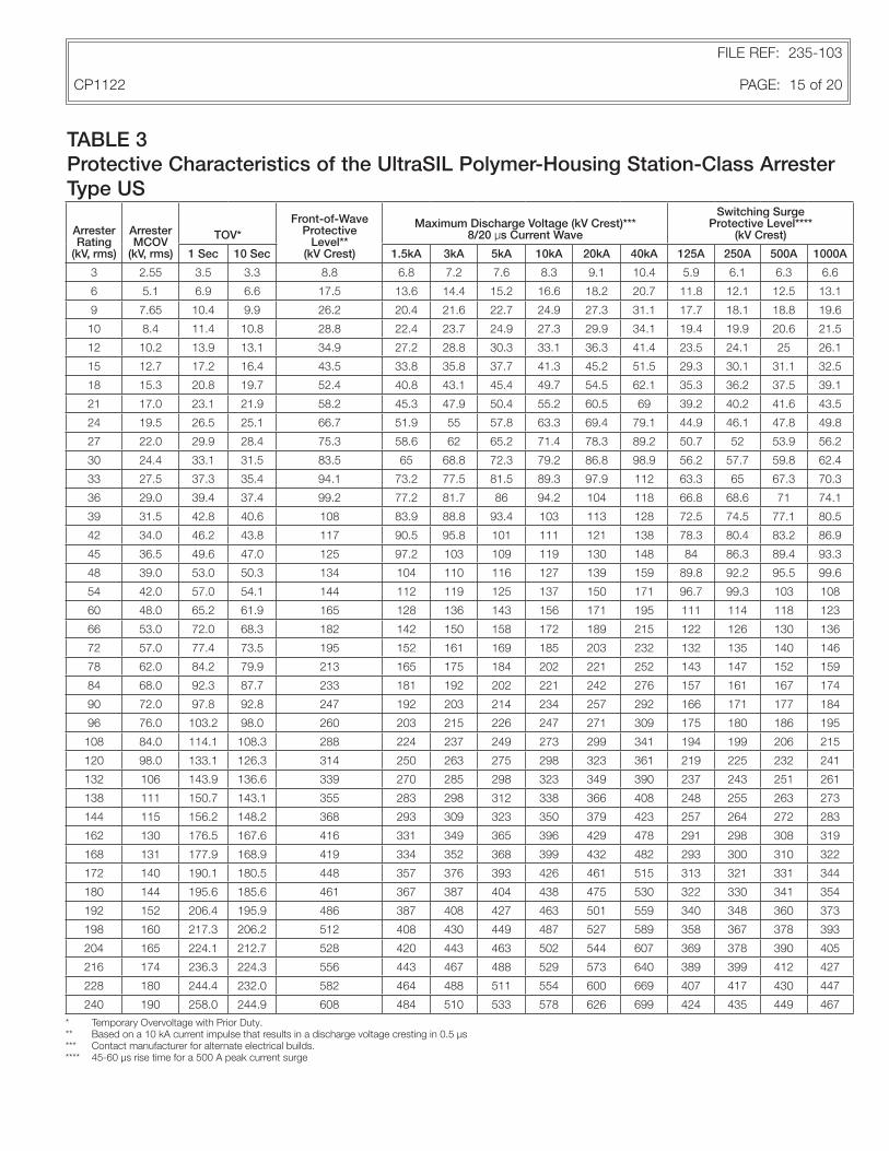
TABLE 3Protective Characteristics of the UltraSIL Polymer-Housing Station-Class Arrester Type US
FILE REF: 235-103
CP1122 PAGE: 15 of 20
Arrester Rating
(kV, rms)
Arrester MCOV
(kV, rms)
TOV*Front-of-Wave
Protective Level**
(kV Crest)
Maximum Discharge Voltage (kV Crest)*** 8/20 μs Current Wave
Switching Surge Protective Level****
(kV Crest)
1 Sec 10 Sec 1.5kA 3kA 5kA 10kA 20kA 40kA 125A 250A 500A 1000A
3 2.55 3.5 3.3 8.8 6.8 7.2 7.6 8.3 9.1 10.4 5.9 6.1 6.3 6.6
6 5.1 6.9 6.6 17.5 13.6 14.4 15.2 16.6 18.2 20.7 11.8 12.1 12.5 13.1
9 7.65 10.4 9.9 26.2 20.4 21.6 22.7 24.9 27.3 31.1 17.7 18.1 18.8 19.6
10 8.4 11.4 10.8 28.8 22.4 23.7 24.9 27.3 29.9 34.1 19.4 19.9 20.6 21.5
12 10.2 13.9 13.1 34.9 27.2 28.8 30.3 33.1 36.3 41.4 23.5 24.1 25 26.1
15 12.7 17.2 16.4 43.5 33.8 35.8 37.7 41.3 45.2 51.5 29.3 30.1 31.1 32.5
18 15.3 20.8 19.7 52.4 40.8 43.1 45.4 49.7 54.5 62.1 35.3 36.2 37.5 39.1
21 17.0 23.1 21.9 58.2 45.3 47.9 50.4 55.2 60.5 69 39.2 40.2 41.6 43.5
24 19.5 26.5 25.1 66.7 51.9 55 57.8 63.3 69.4 79.1 44.9 46.1 47.8 49.8
27 22.0 29.9 28.4 75.3 58.6 62 65.2 71.4 78.3 89.2 50.7 52 53.9 56.2
30 24.4 33.1 31.5 83.5 65 68.8 72.3 79.2 86.8 98.9 56.2 57.7 59.8 62.4
33 27.5 37.3 35.4 94.1 73.2 77.5 81.5 89.3 97.9 112 63.3 65 67.3 70.3
36 29.0 39.4 37.4 99.2 77.2 81.7 86 94.2 104 118 66.8 68.6 71 74.1
39 31.5 42.8 40.6 108 83.9 88.8 93.4 103 113 128 72.5 74.5 77.1 80.5
42 34.0 46.2 43.8 117 90.5 95.8 101 111 121 138 78.3 80.4 83.2 86.9
45 36.5 49.6 47.0 125 97.2 103 109 119 130 148 84 86.3 89.4 93.3
48 39.0 53.0 50.3 134 104 110 116 127 139 159 89.8 92.2 95.5 99.6
54 42.0 57.0 54.1 144 112 119 125 137 150 171 96.7 99.3 103 108
60 48.0 65.2 61.9 165 128 136 143 156 171 195 111 114 118 123
66 53.0 72.0 68.3 182 142 150 158 172 189 215 122 126 130 136
72 57.0 77.4 73.5 195 152 161 169 185 203 232 132 135 140 146
78 62.0 84.2 79.9 213 165 175 184 202 221 252 143 147 152 159
84 68.0 92.3 87.7 233 181 192 202 221 242 276 157 161 167 174
90 72.0 97.8 92.8 247 192 203 214 234 257 292 166 171 177 184
96 76.0 103.2 98.0 260 203 215 226 247 271 309 175 180 186 195
108 84.0 114.1 108.3 288 224 237 249 273 299 341 194 199 206 215
120 98.0 133.1 126.3 314 250 263 275 298 323 361 219 225 232 241
132 106 143.9 136.6 339 270 285 298 323 349 390 237 243 251 261
138 111 150.7 143.1 355 283 298 312 338 366 408 248 255 263 273
144 115 156.2 148.2 368 293 309 323 350 379 423 257 264 272 283
162 130 176.5 167.6 416 331 349 365 396 429 478 291 298 308 319
168 131 177.9 168.9 419 334 352 368 399 432 482 293 300 310 322
172 140 190.1 180.5 448 357 376 393 426 461 515 313 321 331 344
180 144 195.6 185.6 461 367 387 404 438 475 530 322 330 341 354
192 152 206.4 195.9 486 387 408 427 463 501 559 340 348 360 373
198 160 217.3 206.2 512 408 430 449 487 527 589 358 367 378 393
204 165 224.1 212.7 528 420 443 463 502 544 607 369 378 390 405
216 174 236.3 224.3 556 443 467 488 529 573 640 389 399 412 427
228 180 244.4 232.0 582 464 488 511 554 600 669 407 417 430 447
240 190 258.0 244.9 608 484 510 533 578 626 699 424 435 449 467
* Temporary Overvoltage with Prior Duty.** Based on a 10 kA current impulse that results in a discharge voltage cresting in 0.5 μs*** Contact manufacturer for alternate electrical builds.**** 45-60 μs rise time for a 500 A peak current surge

TABLE 4Protective Characteristics of the UltraSIL Polymer-Housing Station-Class Arrester Type UH
FILE REF: 235-103
CP1122 PAGE: 16 of 20
* Temporary Overvoltage with Prior Duty.** Based on a 10 kA current impulse that results in a discharge voltage cresting in a 0.5 μs *** Contact manufacturer for alternate electrical builds.**** 45-60 μs rise time for a 500 A peak current surge.
Arrester Rating
(kV, rms)
Arrester MCOV
(kV, rms)
TOV*Front-of-Wave
Protective Level**
(kV Crest)
Maximum Discharge Voltage (kV Crest)*** 8/20 μs Current Wave
Switching Surge Protective Level****
(kV Crest)
1 Sec 10 Sec 1.5kA 3kA 5kA 10kA 20kA 40kA 125A 250A 500A 1000A
3 2.55 3.5 3.3 8.2 6.5 6.9 7.2 7.8 8.4 9.4 5.7 5.9 6.1 6.3
6 5.1 6.9 6.6 16.3 13 13.7 14.3 15.6 16.8 18.8 11.4 11.7 12.1 12.6
9 7.65 10.4 9.9 24.5 19.5 20.6 21.5 23.3 25.2 28.2 17.1 17.6 18.1 18.8
10 8.4 11.4 10.8 26.9 21.4 22.6 23.6 25.6 27.7 30.9 18.8 19.3 19.9 20.7
12 10.2 13.9 13.1 32.6 26 27.4 28.6 31.1 33.6 37.5 22.8 23.4 24.1 25.1
15 12.7 17.2 16.4 40.6 32.4 34.1 35.6 38.7 41.9 46.7 28.4 29.1 30 31.2
18 15.3 20.8 19.7 48.9 39 41.1 42.9 46.6 50.4 56.3 34.2 35.1 36.2 37.6
21 17.0 23.1 21.9 54.4 43.3 45.6 47.7 51.7 56 62.5 38 39 40.2 41.8
24 19.5 26.5 25.1 62.4 49.7 52.3 54.7 59.3 64.2 71.7 43.6 44.7 46.1 47.9
27 22.0 29.9 28.4 70.3 56 59 61.7 66.9 72.5 80.9 49.1 50.4 52 54
30 24.4 33.1 31.5 78 62.1 65.5 68.4 74.2 80.4 89.7 54.5 55.9 57.7 59.9
33 27.5 37.3 35.4 87.9 70 73.8 77.1 83.6 90.6 102 61.4 63 65 67.5
36 29.0 39.4 37.4 92.7 73.8 77.8 81.3 88.2 95.5 107 64.8 66.4 68.6 71.2
39 31.5 42.8 40.6 101 80.2 84.5 88.3 95.8 104 116 70.3 72.2 74.5 77.3
42 34.0 46.2 43.8 109 86.6 91.2 95.3 104 112 125 75.9 77.9 80.4 83.5
45 36.5 49.6 47.0 117 92.9 97.9 103 111 121 135 81.5 83.6 86.3 89.6
48 39.0 53.0 50.3 125 99.3 105 110 119 129 144 87.1 89.3 92.2 95.7
54 42.0 57.0 54.1 135 107 113 118 128 139 155 93.8 96.2 99.3 104
60 48.0 65.2 61.9 154 123 129 135 146 159 177 108 110 114 118
66 53.0 72.0 68.3 170 135 143 149 162 175 195 119 122 126 131
72 57.0 77.4 73.5 183 146 153 160 174 188 210 128 131 135 140
78 62.0 84.2 79.9 199 158 167 174 189 205 228 139 142 147 153
84 68.0 92.3 87.7 218 174 183 191 207 224 250 152 156 161 167
90 72.0 97.8 92.8 231 184 194 202 219 238 265 161 165 171 177
96 76.0 103.2 98.0 243 194 204 214 232 251 280 170 174 180 187
108 84.0 114.1 108.3 269 214 226 236 256 277 309 188 193 199 207
120 98.0 133.1 126.3 297 242 253 263 284 303 334 214 219 226 234
132 106 143.9 136.6 321 262 274 285 307 328 361 232 237 244 253
138 111 150.7 143.1 336 274 287 298 321 343 378 243 248 256 265
144 115 156.2 148.2 348 284 297 309 333 356 392 251 257 265 274
162 130 176.5 167.6 394 321 336 349 376 402 443 284 291 300 310
168 131 177.9 168.9 397 323 339 352 379 405 446 286 293 302 312
172 140 190.1 180.5 424 346 362 376 405 433 477 306 313 323 334
180 144 195.6 185.6 436 355 372 387 417 445 491 315 322 332 343
192 152 206.4 195.9 460 375 393 408 440 470 518 332 340 350 362
198 160 217.3 206.2 485 395 413 430 463 495 545 350 358 369 382
204 165 224.1 212.7 500 407 426 443 477 510 562 361 369 380 393
216 174 236.3 224.3 527 429 450 467 503 538 593 380 389 401 415
228 180 244.4 232.0 551 449 470 489 526 563 620 398 407 419 434
240 190 258.0 244.9 575 469 491 510 550 587 647 415 425 438 453

TABLE 5Protective Characteristics of the UltraSIL Polymer-Housing Station-Class Arrester Type UX
FILE REF: 235-103
CP1122 PAGE: 17 of 20
* Temporary Overvoltage with Prior Duty.** Based on a 10 kA current impulse that results in a discharge voltage cresting in a 0.5 μs *** Contact manufacturer for alternate electrical builds.**** 45-60 μs rise time for a 500 A peak current surge.
Arrester Rating
(kV, rms)
Arrester MCOV
(kV, rms)
TOV* Front-of-Wave Protective Level**
(kV Crest)
Maximum Discharge Voltage (kV Crest) 8/20 μs Current Wave
Switching Surge Protective Level***
(kV Crest)
1 Sec 10 Sec 1.5kA 3kA 5kA 10kA 20kA 40kA 125A 250A 500A 1000A
3 2.55 3.5 3.3 7.8 6.3 6.6 6.9 7.4 7.9 8.7 5.6 5.7 5.9 6.1
6 5.1 6.9 6.6 15.5 12.6 13.2 13.7 14.8 15.8 17.4 11.2 11.4 11.8 12.2
9 7.65 10.4 9.9 23.2 18.9 19.8 20.6 22.2 23.7 26.1 16.7 17.1 17.6 18.3
10 8.4 11.4 10.8 25.5 20.8 21.7 22.6 24.3 26 28.6 18.4 18.8 19.4 20.1
12 10.2 13.9 13.1 30.9 25.2 26.4 27.4 29.5 31.6 34.8 22.3 22.8 23.5 24.3
15 12.7 17.2 16.4 38.5 31.4 32.8 34.1 36.8 39.3 43.3 27.8 28.4 29.3 30.3
18 15.3 20.8 19.7 46.3 37.8 39.5 41.1 44.3 47.3 52.1 33.4 34.2 35.2 36.5
21 17.0 23.1 21.9 51.5 42 43.9 45.6 49.2 52.6 57.9 37.1 38 39.2 40.5
24 19.5 26.5 25.1 59.1 48.1 50.4 52.3 56.4 60.3 66.4 42.6 43.6 44.9 46.5
27 22.0 29.9 28.4 66.6 54.3 56.8 59.1 63.6 68 74.9 48.1 49.2 50.7 52.4
30 24.4 33.1 31.5 73.9 60.2 63 65.5 70.6 75.4 83.1 53.3 54.6 56.2 58.2
33 27.5 37.3 35.4 83.3 67.8 71 73.8 79.5 85 93.7 60.1 61.5 63.3 65.5
36 29.0 39.4 37.4 87.8 71.5 74.9 77.8 83.9 89.6 98.8 63.3 64.8 66.8 69.1
39 31.5 42.8 40.6 95.4 77.7 81.3 84.5 91.1 97.4 108 68.8 70.4 72.5 75.1
42 34.0 46.2 43.8 103 83.9 87.8 91.2 98.3 106 116 74.2 76 78.3 81
45 36.5 49.6 47.0 111 90 94.2 97.9 106 113 125 79.7 81.6 84 87
48 39.0 53.0 50.3 119 96.2 101 105 113 121 133 85.1 87.2 89.8 92.9
54 42.0 57.0 54.1 128 104 109 113 122 130 143 91.7 93.9 96.7 101
60 48.0 65.2 61.9 146 119 124 129 139 149 164 105 108 111 115
66 53.0 72.0 68.3 161 131 137 143 154 164 181 116 119 122 127
72 57.0 77.4 73.5 173 141 148 153 165 177 195 125 128 132 136
78 62.0 84.2 79.9 188 153 161 167 180 192 212 136 139 143 148
84 68.0 92.3 87.7 206 168 176 183 197 211 232 149 152 157 162
90 72.0 97.8 92.8 218 178 186 194 209 223 246 158 161 166 172
96 76.0 103.2 98.0 230 188 197 204 220 235 259 166 170 175 181
108 84.0 114.1 108.3 255 208 217 226 243 260 286 184 188 194 201

GRAPH 1
TOV Recovery Curve of VariSTAR Type US, UH, and UX Station-Class Surge Arresters
FILE REF: 235-103
CP1122 PAGE: 18 of 20
* The energy absorbed in the prior duty test was 3.9 kJ/kV of MCOV for type US (3-108 kV) arresters. For Type US (120-240 kV) and UH (3-108 kV), the energy was 6.2 kJ/kV of MCOV. For Type UH (120-240 kV) and UX (3-108 kV) the energy was 10 kJ/kV of MCOV.
TABLE 6TOV Recovery Capability of VariSTAR Type US, UH, and UX Station-Class Surge Arresters
1.600
1.500
1.400
1.300
1.200
1.100
1.000
1.486
1.417
1.348
1.279
1.210
1.141
1.427
1.358
1.289
1.220
1.151
1.082
0.1 1 10 100 1000 10000
Time (sec)
Volta
ge (p
er u
nit C
OV
)
Time (Seconds)
TOV (Per unit MCOV)
No Prior Duty Prior Duty
0.1 1.486 1.427
1 1.417 1.358
10 1.348 1.289
100 1.279 1.220
1000 1.210 1.151
10000 1.141 1.082

FILE REF: 235-103
CP1122 PAGE: 19 of 20
This page intentionally left blank.
FILE REF: 235-103
CP1122 PAGE: 20 of 20
2300 Badger Drive Waukesha, WI 53188 USA
© 2012 Cooper Industries. All Rights Reserved Cooper Power Systems, VariSTAR and UltraSIL are valuable trademarks of Cooper Industries in the U.S. and other countries. You are not permitted to use the Cooper Trademark without the prior written consent of Cooper Industries.IEEE is a registered trademark of the Institute of Electrical and Electronics Engineers, Inc.IEEE Std C62.11™-2005 and IEEE Std C62.11a™-2008 standards are trademarks of the Institute of Electrical and Electronics Engineers, Inc., (IEEE). This publication/product is not endorsed or approved by the IEEE.
One Cooper | www.cooperpower.com | Online