COVERS MODEL 4510 - Traxxas · This manual contains the instructions you will need to operate and...
15
OPERATING INSTRUCTIONS COVERS MODEL 4510 KC1149-R01 Rev 090806
Transcript of COVERS MODEL 4510 - Traxxas · This manual contains the instructions you will need to operate and...

OPERATING INSTRUCTIONSCOVERS MODEL 4510
KC1149-R01 Rev 090806
WARNING!Carefully read and follow all instructions in this and any accompanying materials to prevent serious damage to your model. Failure to follow these instructions will be considered abuse and/or neglect.
INTRODUCTION
Thank you for purchasing the Traxxas Nitro Sport. This manual contains the instructions you will need to operate and maintain your Nitro Sport. Look over the manual and examine the Nitro Sport carefully before running it. If for some reason you think the Nitro Sport is not what you wanted, then do not continue any further. Your hobby dealer absolutely cannot accept a Nitro Sport for return or exchange after it has been run.
Please read all of the operating instructions and precautions before attempting to drive the Nitro Sport. Even if you are an experienced R/C enthusiast, continue reading to learn about Nitro Sport’s unique features. Pay special attention to the mechanical and safety precautions outlined in the manual.
If you have any questions about your new model, feel free to call Traxxas’ technical support line toll-free at 1-888-TRAXXAS (1-888-872-9927) Outside the U.S. call 972-265-8000. Technical support is available Monday through Friday, from 8:30am to 9:00pm Central Standard Time. Technical assistance is also available through our website at Traxxas.com (e-mail us at [email protected]). We hope that you will enjoy many hours of fun with your new Nitro Sport.
FUEL
It’s imperative that you use the correct fuel in your Pro.15 engine for maximum performance and engine life. Traxxas Top Fuel® Power Plus™ should be used to ensure correct engine lubrication, performance, and ease of tuning.
• Top Fuel is the only fuel which is 100% certified for use in Traxxas engines. • Traxxas Top Fuel is made with just the right balance of natural and
synthetic lubricants to allow excellent throttle response and the best top-end performance, without sacrificing long-term durability.
You may use 10% or 20% nitro-content fuel. Try to use the same percentage all the time, avoid switching back and forth between fuels. We recommend that if you break in your engine on 20% fuel that you stick with that percentage. If you do move to a higher or lower percentage, make sure you readjust your fuel mixture to compensate.
Can other brands of fuel be used besides Top Fuel? There are other fuels that can provide satisfactory performance; however, there could be long-term costs in the form of decreased engine performance, loss of tuning ease, and shorter engine life. Only use fuels that contain both castor and synthetic oil.
Everyone has an opinion or a claim to make about fuel. The engineering team at Traxxas has spent years developing Traxxas engines. No one knows more about the specific fuel requirements of Traxxas engines, than Traxxas engineers. We strongly urge you not to take chances with your engine investment and use the Traxxas fuel made for Traxxas engines.
FUEL BOTTLE
Fuel is usually purchased by the gallon or quart, so a smaller bottle with a dispensing tube is required to fill the fuel tank. The fuel tank in the Nitro Sport has a capacity of 75cc. The fuel bottle should always be capped to prevent the fuel from evaporating and becoming contaminated with debris or moisture. The alcohol and nitro contents of the fuel will evaporate, thus upsetting the fuel balance and spoiling the fuel. Do not use old or dirty fuel!
Included Fuel Bottle(Part #5001)
PERSONAL SAFETY PRECAUTIONS Every precaution outlined in this manual needs to be followed to help ensure
safe operation. Operate your model sensibly and with care and it will be exciting, safe, and fun for you and your spectators. Failure to operate your model in a safe and responsible manner could result in property damage and serious injury. You alone must see to it that the instructions are followed and the precautions are adhered to.
The Nitro Sport is not intended for use by children without the supervision of a responsible adult. Traxxas shall not be liable for any loss or damages, whether direct, indirect, special, incidental, or consequential, arising from the use, misuse, or abuse of this product and any chemical or accessory required to operate this product.
• Nitro Sport is very fast! Children under 16 years of age and inexperienced drivers should not operate the Nitro Sport without the supervision of a responsible and knowledgeable (experienced) adult.
• Model engine fuel is dangerous and highly poisonous. Always follow all directions and precautions printed on the fuel container. Model engine fuel is poisonous to humans and animals. Drinking the fuel can cause blindness and death. Handle with care and respect.
• Model engine fuel, especially when in a fuel dispensing bottle, may look like a cool drink to a child. Keep all fuel out of the reach of children at all times. Do not place fuel containers on the ground where children can reach them while you are driving.
• Model engine fuel is flammable. Never allow smoking, sparks, heat or flame in the presence of fuel or fuel vapors.
• The engine, brakes, and exhaust system may become extremely hot during use. Be careful not to touch the parts, especially when refueling or stopping the engine.
• Prolonged exposure to the engine exhaust can be harmful. Avoid breathing the engine exhaust. Always run your Nitro Sport outdoors, in a well-ventilated area. Never run the engine indoors.
• Do not operate your Nitro Sport at night, or anytime your line of sight to the model may be obstructed or impaired in any way.
• Never operate your Nitro Sport in crowds of people or busy pedestrian areas. Nitro Sport is very fast and could cause injury to those unaware of its presence. Keep small children at a safe distance away from the operating area.
• Because Nitro Sport is controlled by radio, it is subject to radio interference from many sources beyond your control. Since radio interference can cause momentary loss of control, always allow a safety margin in all directions around your model to prevent collisions.
• The engine can be loud. If the noise makes you uncomfortable, wear ear protection. Be considerate of your neighbors by not running your model early in the morning or late in the evening.
• Most importantly, use good common sense at all times.
Batteries and Battery ChargingYour model uses rechargeable batteries that must be handled with care for safety and long battery life. Make sure to read and follow all instructions and precautions that were provided with the battery packs and your charger. It is your responsibility to charge and care for the battery packs properly. In addition toyour battery and charger instructions, here are some more tips to keep in mind.
• Use the supplied charger to charge the included battery. See “Charging the EZ-Start Battery” on page 5.
• Never leave batteries to charge unattended.
• Allow the battery pack to cool off before charging.
• Do not use battery packs that have been damaged in any way.
• Do not use battery packs that have damaged wiring, exposed wiring, or a damaged connector.
• Children should have responsible adult supervision when charging and handling batteries.
• Only use approved chargers for NiMH battery packs (such as Part #2921 or the Traxxas TRX Power Charger, Part #3030X). Do not exceed the maximum charge rate of 1 amp.
• Do not short-circuit the battery pack. This may cause burns and severe damage to the battery pack
• Do not burn or puncture the batteries. Toxic materials could be released. If eye or skin contact occurs, flush with water.
• Store the battery pack in a dry location, away from heat sources and direct sunlight.
• Nickel Metal Hydride batteries must be recycled or disposed of properly. 2
3
OTHER REQUIRED EQUIPMENT
To operate the Nitro Sport, you will need these additional items. All of these items should be available from your hobby shop. 1. 12 “AA” size batteries for your transmitter (8) and receiver (4)2. Small Phillips head and flat screwdrivers (for adjustments)3. After-run oil (to protect the engine from corrosion)
THE TQ RADIO SYSTEM
The Nitro Sport Model 4510 is equipped with the 2-channel TQ radio system. The following radio system terms will be used throughout the rest of these operating instructions.
Channel - The 27 MHz frequency band is divided into 6 channels so that up to six models can be operated simultaneously. Each channel is referred to by its flag color and channel number, as shown below.
Clearing your frequency - A routine, verbal check to make sure nobody else in your area is operating on the same channel. Always clear your frequency by calling out your channel number before operating your model. Wait or move to another area if your channel is already being used.
Crystal (X-tal) - The plug-in device that determines on which channel the radio system will operate. For each channel, there are two crystals, one for the receiver and one for the transmitter. Of those two crystals, the one marked “RX” with the lower number (.455 MHz lower) must be inserted into the receiver.
Frequency band - The radio frequency used by the transmitter to send signals to your Nitro Sport. All Traxxas RTR models operate on a 27 MHz frequency band.
mah – Abbreviation for milliamp hour. Measure of the capacity of the battery pack. The higher the number, the longer the battery will last between recharges.
Neutral position - The standing position that the servos seek when the transmitter controls are at the neutral setting.
NiCad - Abbreviation for nickel-cadmium. The original rechargeable hobby pack, NiCad batteries have very high current handling, high capacity, and can last up to 1000 charging cycles. Good charging procedures are required to reduce the possibility of developing a “memory” effect and shortened run times.
NiMH - Abbreviation for nickel-metal hydride. Rechargeable NiMH batteries offer high current handling, and much greater resistance to the “memory” effect. NiMH batteries generally allow higher capacity than NiCad batteries. They can last up to 500 charge cycles. A peak charger designed for NiMH batteries is required for optimal performance.
Receiver - The radio unit inside your Nitro Sport that receives signals from the transmitter and relays them to the servos.
Servos - Small motor units in your Nitro Sport that operate the throttle and steering mechanisms.
Two-channel radio system - The TQ radio system, consisting of the receiver, the transmitter, and the servos. The system uses two channels: one to operate the throttle and one to operate the steering.
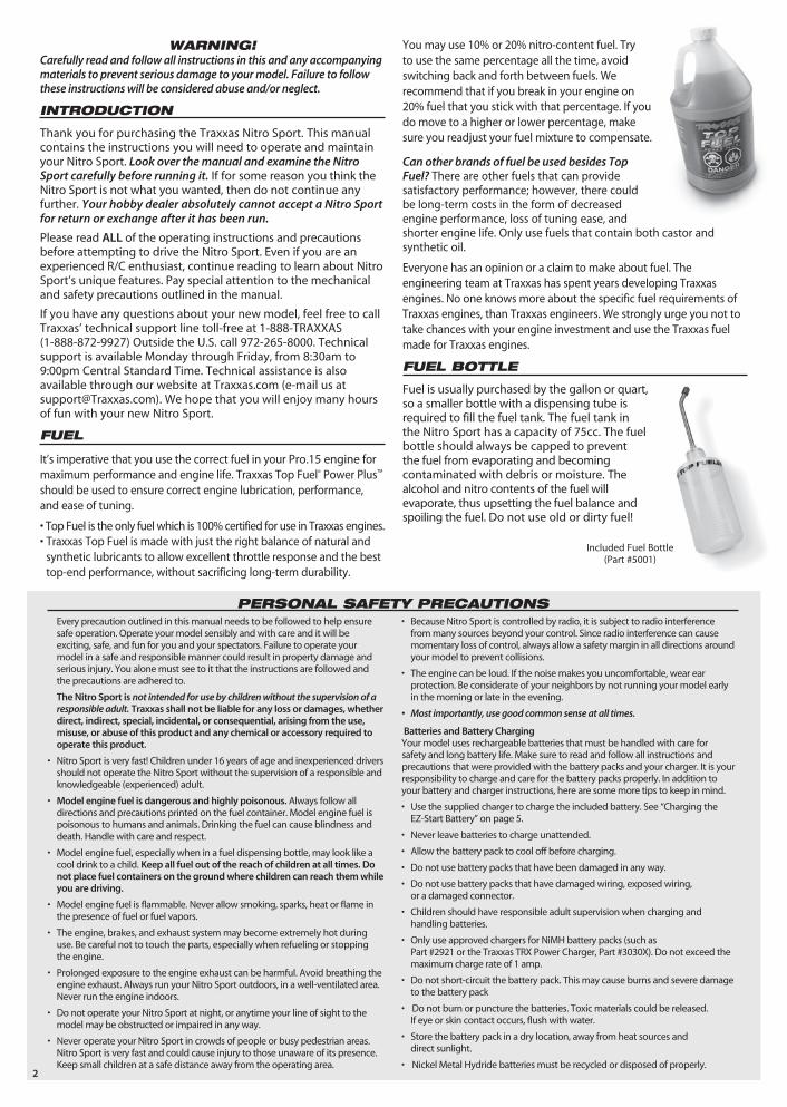
Transmitter - The hand-held radio unit that sends throttle and steering instructions to your Nitro Sport.
Trim - The fine-tuning adjustment of the neutral position of the servos, made by turning the throttle and steering trim knobs on the face of the transmitter.
INSTALLING TRANSMITTER BATTERIES
Install 8 AA batteries into the bottom of the transmitter as shown in the drawing.
Antenna
Power Indicator
Steering Trim
Throttle Trim
Throttle Neutral Adjust
Throttle Trigger
Steering Wheel
Power Switch
Servo Reversing SwitchesSteering (R), Throttle (L)
BatteryCompartment
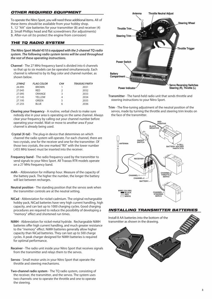
27MHZ FLAG COLOR CH# TRAXXAS PART#26.995 BROWN 1 203127.045 RED 2 203227.095 ORANGE 3 203327.145 YELLOW 4 203427.195 GREEN 5 203527.255 BLUE 6 2036
CHANNEL-1STEERING
SERVO
CHANNEL-2THROTTLE
SERVO
4-CELLBATTERY HOLDER
PART# 3170
CHANNEL-1
ANTENNA
RECEIVER
ON/OFFSWITCH
BLACKNEGATIVE
REDPOSITIVE
CHANNEL-2
BATTERY
WIRE COLORSBLACKREDWHITE

RADIO SYSTEM ADJUSTMENTS Throttle Neutral adjustThe throttle neutral adjustment is located on the transmitter face and controls the forward and reverse travel of the throttle trigger. There are two settings, 50/50 which allows equal travel for both forward and brake, and 70/30 which allows more travel for throttle and less for brake. Change the adjustment by pressing the button and sliding it to the desired position. 70/30 is the recommended setting while running the Nitro Sport.
Servo Reversing SwitchesOn the front of the transmitter there are two switches. One for throttle and one for steering. Moving the switches reverses the direction of the corresponding servos. For example, if you turn your steering wheel right and the model moves left, then switch the steering servo reversing switch to correct the servo direction. You may need to adjust the corresponding trim control after moving the servo-reversing switch.
TOTAL TRIGGER
MOVEMENT
50%REVERSE
50%FORWARD
4
INSTALLING RECEIVER BATTERIES
The receiver battery holder is located underneath the battery cover. Remove the battery cover by removing the two body clips from the posts on both sides of the battery holder. Install 4 AA batteries into the battery holder. Alkaline batteries should be used. Place the battery holder into the battery cover with the cushioning foam. Secure the battery cover to the chassis using the two body clips as shown.
ANTENNA SETUP
Locate the plastic tube and the antenna tip (supplied in the bag with your instructions). Insert the black antenna wire, extending from the receiver housing, into one end of the tube and push it all the way through. Spray the wire with glass cleaner to make it easier to insert. Insert the tube into the antenna mount on the side of the chassis. Fold the remaining antenna wire over the top of the antenna tube and secure it with the vinyl antenna tip.
Under no circumstances should you ever cut your antenna wire. Its length is specially tuned to the frequency band, and cutting it could severely shorten the radio’s range. On the transmitter, fully extend the chrome telescopic antenna.
RADIO SYSTEM OPERATION
Your radio system was pre-adjusted before it left the factory, however, the adjustment should be checked prior to running the truck.
1. Before you ever turn your radio system on, you must “clear” your frequency. There are six different channels numbered 1 through 6. Each of the six channels is represented by a color. Look at the crystal in the back of the transmitter to determine which of the channels your truck is operating. Clearing your frequency means checking to be sure that no one else in the area is operating on the same channel.
2. always turn the transmitter on first and off last. This will prevent the model from receiving stray signals and running out of control. Slide the transmitter switch to the “on” position. A steady red light should illuminate. a flashing red light indicates weak batteries. Weak batteries will limit the range of the radio signal between your transmitter and receiver. Loss of the radio signal can cause you to lose control of the truck.
3. Turn the truck on. The switch is located on the chassis. The servos should jump and move to their idle (neutral) positions.
4. With the front wheels off the ground, operate the steering control on the transmitter (channel 1). Check for rapid operation of the steering servo and that the steering mechanism is not loose or binding. If the servo operates slowly, check for weak batteries. Turn the “steering trim” control on the transmitter to adjust the servo so that the front wheels are pointing straight ahead. Check to be sure that the wheels do not turn more in one direction than in the other.
5. Operate the throttle trigger on the transmitter to ensure that the throttle servo is operating properly. When the servo is in the neutral position, the carburetor should be in its idle position (you will adjust the engine idle speed later). When the throttle trigger is pulled all of the way, the carburetor should be in the fully-open position. When the throttle lever is pushed forward, the brake should be locked and the throttle should not close any further than when at idle.
RANGE TEST THE RADIO
There are many things such as buildings, power lines, radio transmitters, etc. which can adversely affect the performance of your radio system. To make sure you do not have a “runaway” model, range test the radio system. With the radio system on and working, hold the truck and have a friend carry the transmitter away from you the distance you plan to run the truck. Have the friend operate the controls on the transmitter to be sure that everything is working at full range.
CH.2
CH.1
NOTE: Never turn the transmitter or receiver off while the engine is
running. The model could run out of control. (The on/off switch only turns the receiver on and off. It does not turn off the engine.)
CH.2
CH.1
0°0°
1°-2°1°-2°
-1° -1°
5
PREPARING TO RUN
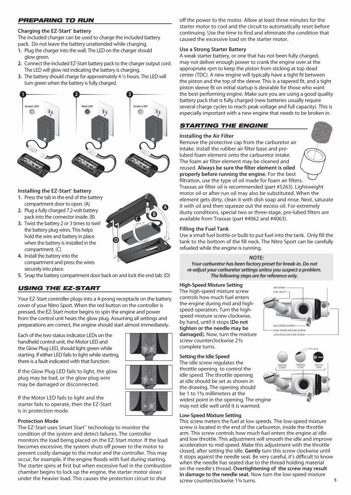
Charging the EZ-Start® batteryThe included charger can be used to charge the included battery pack. Do not leave the battery unattended while charging. 1. Plug the charger into the wall. The LED on the charger should
glow green. 2. Connect the included EZ-Start battery pack to the charger output cord.
The LED will glow red indicating the battery is charging.3. The battery should charge for approximately 4 ½ hours. The LED will
turn green when the battery is fully charged.
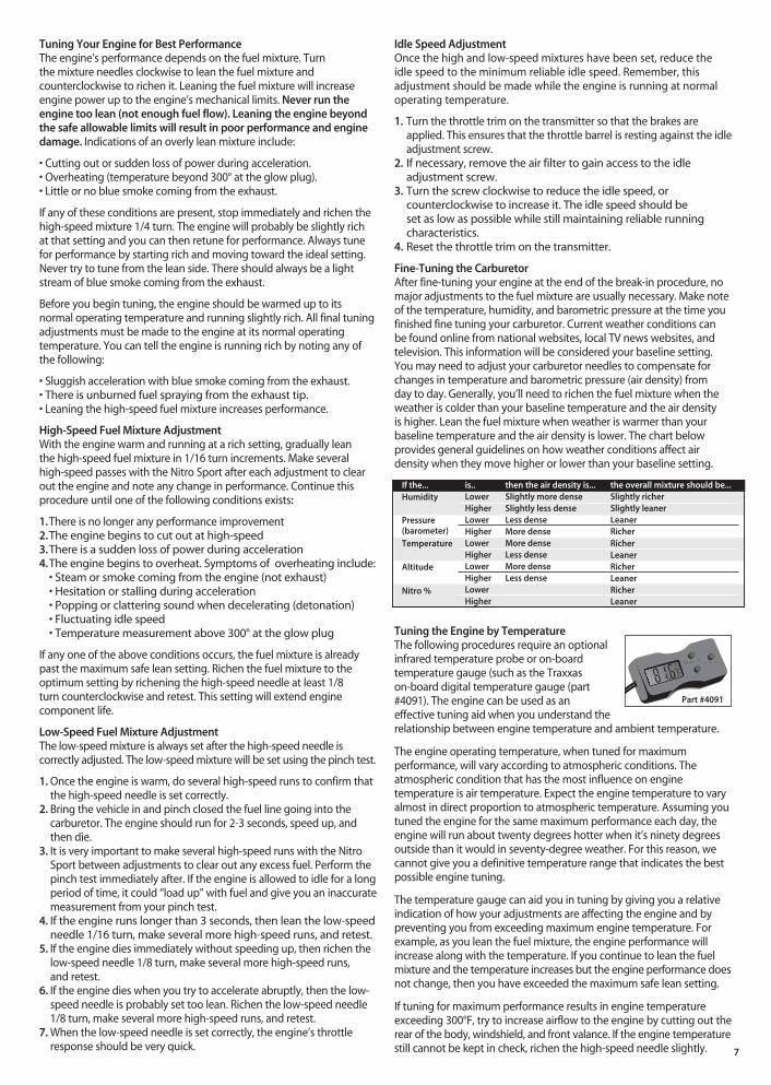
Installing the EZ-Start® battery1. Press the tab in the end of the battery
compartment door to open. (A)2. Plug a fully charged 7.2-volt battery
pack into the connector inside. (B)3. Twist the battery 2 or 3 times to twirl
the battery plug wires. This helps hold the wire and battery in place when the battery is installed in the compartment. (C)
4. Install the battery into the compartment and press the wires securely into place.
5. Snap the battery compartment door back on and lock the end tab. (D)
USING THE EZ-START
Your EZ-Start controller plugs into a 4-prong receptacle on the battery cover of your Nitro Sport. When the red button on the controller is pressed, the EZ-Start motor begins to spin the engine and power from the control unit heats the glow plug. Assuming all settings and preparations are correct, the engine should start almost immediately.
Each of the two status indicator LEDs on the handheld control unit, the Motor LED and the Glow Plug LED, should light green while starting. If either LED fails to light while starting, there is a fault indicated with that function:
If the Glow Plug LED fails to light, the glow plug may be bad, or the glow plug wire may be damaged or disconnected.
If the Motor LED fails to light and the starter fails to operate, then the EZ-Start is in protection mode.
Protection ModeThe EZ-Start uses Smart Start™ technology to monitor the condition of the system and detect failures. The controller monitors the load being placed on the EZ-Start motor. If the load becomes excessive, the system shuts off power to the motor to prevent costly damage to the motor and the controller. This may occur, for example, if the engine floods with fuel during starting. The starter spins at first but when excessive fuel in the combustion chamber begins to lock up the engine, the starter motor slows under the heavier load. This causes the protection circuit to shut
off the power to the motor. Allow at least three minutes for the starter motor to cool and the circuit to automatically reset before continuing. Use the time to find and eliminate the condition that caused the excessive load on the starter motor.
Use a Strong Starter Battery A weak starter battery, or one that has not been fully charged, may not deliver enough power to crank the engine over at the appropriate rpm to keep the piston from sticking at top dead center (TDC). A new engine will typically have a tight fit between the piston and the top of the sleeve. This is a tapered fit, and a tight piston sleeve fit on initial startup is desirable for those who want the best-performing engine. Make sure you are using a good quality battery pack that is fully charged (new batteries usually require several charge cycles to reach peak voltage and full capacity). This is especially important with a new engine that needs to be broken in.
STARTING THE ENGINE
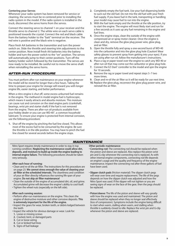
Installing the air FilterRemove the protective cap from the carburetor air intake. Install the rubber air filter base and pre-lubed foam element onto the carburetor intake. The foam air filter element may be cleaned and reused. always be sure the filter element is oiled properly before running the engine. For the best filtration, use the type of oil made for foam air filters. Traxxas air filter oil is recommended (part #5263). Lightweight motor oil or after-run oil may also be substituted. When the element gets dirty, clean it with dish soap and rinse. Next, saturate it with oil and then squeeze out the excess oil. For extremely dusty conditions, special two or three-stage, pre-lubed filters are available from Traxxas (part #4062 and #4063).
Filling the Fuel Tank Use a small fuel bottle or bulb to put fuel into the tank. Only fill the tank to the bottom of the fill neck. The Nitro Sport can be carefully refueled while the engine is running.
High-Speed Mixture SettingThe high-speed mixture screw controls how much fuel enters the engine during mid and high-speed operation. Turn the high-speed mixture screw clockwise, by hand, until it stops (Do not tighten or the needle may be damaged). Now, turn the mixture screw counterclockwise 2½ complete turns.
Setting the Idle SpeedThe idle screw regulates the throttle opening to control the idle speed. The throttle opening at idle should be set as shown in the drawing. The opening should be 1 to 1½ millimeters at the widest point in the opening. The engine may not idle well until it is warmed.
low-Speed Mixture SettingThis screw meters the fuel at low speeds. The low-speed mixture screw is located in the end of the carburetor, inside the throttle arm. This screw controls how much fuel enters the engine at idle and low throttle. This adjustment will smooth the idle and improve acceleration to mid-speed. Make this adjustment with the throttle closed, after setting the idle. Gently turn this screw clockwise until it stops against the needle seat. Be very careful, it’s difficult to know when the needle has seated due to the thread holding material on the needle’s thread. Overtightening of the screw may result in damage to the needle seat. Now turn the low-speed mixture screw counterclockwise 1¾ turns.
NOTE: Your carburetor has been factory preset for break-in. Do not
re-adjust your carburetor settings unless you suspect a problem. The following steps are for reference only.
Mo
tor
Glo
w
Plu
g
Mo
tor
Glo
w
Plu
g
Mo
tor
Glo
w
Plu
g
Mo
tor
Glo
w
Plu
g
Mo
tor
Glo
w
Plu
g
Mo
tor
Glo
w
Plu
g
Mo
tor
Glo
w
Plu
g
Mo
tor
Glo
w
Plu
g
Mo
tor
Glo
w
Plu
g
Mo
tor
Glo
w
Plu
g
Mo
tor
Glo
w
Plu
g
Mo
tor
Glo
w
Plu
g
Mo
tor
Glo
w
Plu
g
Mo
tor
Glo
w
Plu
g
Mo
tor
Glo
w
Plu
g
Mo
tor
Glo
w
Plu
g
Mo
tor
Glo
w
Plu
g
Mo
tor
Glo
w
Plu
g
Mo
tor
Glo
w
Plu
g
Mo
tor
Glo
w
Plu
g
Mo
tor
Glo
w
Plu
g
Mo
tor
Glo
w
Plu
g
Mo
tor
Glo
w
Plu
g
Mo
tor
Glo
w
Plu
g
Mo
tor
Glo
w
Plu
g
Mo
tor
Glo
w
Plu
g
Mo
tor
Glo
w
Plu
g
Green LED Green LEDRed LEDGreen LED Green LEDRed LEDGreen LED Green LEDRed LED
aB
C
D
2 31

DRIVING PRECAUTIONS• The radio system is not waterproof. Avoid driving through puddles,
wet grass, or mud. Water could damage the electronics.• Do not continue to operate the Nitro Sport with low batteries.
After the battery power drops below a certain point, the model will continue with the last command it had from the transmitter. Indications of low battery power include slow operation and sluggish servos. On the transmitter, a flashing red light indicates low transmitter batteries.
• Do not drive the Nitro Sport at night, on public streets, or in large crowds of people.
• If the truck becomes stuck, do not continue to run the engine. Remove the obstruction before continuing to drive.
• Do not attempt to push or tow objects with the Nitro Sport.• The model is controlled by radio. It is subject to radio
interference from many sources beyond your control. Since radio interference can cause momentary loss of control, allow a safety margin around the truck in order to prevent collisions.
• Use common sense whenever you are driving your model. Intentionally driving in an abusive and rough manner will only result in poor performance and broken parts.
6
Shutting Off the Engine Before starting the engine it is important to know how to shut it off. The correct method is to pinch and hold the carburetor’s fuel line at idle speed, until the engine dies.
Starting the EngineBefore you start your engine for the first time, make sure you have read all instructions and precautions in this manual. Pay close attention to the break-in instructions in the next section, and make sure you have read and understood them before you run your engine.
Your engine must be at room temperature (70°F or 21° C) or above the first time you start it. If it’s cooler than room temperature outside, remove all fuel and keep your model indoors until you’re ready to start it and then take it outside. We do not recommend running the model in temperatures below 35 degrees.
1. Turn on the radio system.2. Make sure the throttle trigger on the transmitter is in the idle
(neutral) position.3. Connect the EZ-Start controller.4. Press the starter button in short two-second bursts and watch
for fuel moving through the fuel line up to the carburetor. Watch closely! The fuel moves very fast. If the fuel doesn’t move through the line within 5 seconds, prime the engine by briefly (one or two seconds) covering the exhaust outlet with your finger until the fuel is just visible in the carburetor fuel line. Watch carefully! If the engine is primed too long, it will flood with fuel and stop turning.
5. Once fuel reaches the carburetor, the engine should quickly start and idle.
6. Disconnect the EZ-Start controller from the model.
7. Proceed with the engine break-in.8. Do not rev your engine with no load (wheels off the ground).
BREAKING-IN THE ENGINE (VERY IMPORTANT!)
Once your engine is running, it must be broken-in. The key to breaking-in your engine is patience. The break-in time will take about 1 to 1½ hours. During the break-in period, your engine may appear to malfunction with symptoms such as stalling, inconsistent performance, and fouled glow plugs. Don’t give up on it! These are just “break-in pains” that every new engine has to go through. They will disappear once you get through the break-in period. Just keep it running, and throttle on and off as smoothly as you can. Sudden bursts or releases of the throttle can stall your engine. Resist the temptation to tune the engine for performance and/or run for extended times at wide open throttle. Soon, after about the fourth tank of fuel, your patience will pay off with solid, consistent performance.
During Break-in...• Special break-in fuels are not required.• Drive the model on a smooth hard surface.• If possible, avoid running on very hot, humid days.
• Run with the body off for extra engine cooling.• Turn the mixture screw (needle) clockwise (in) to lean the mixture
and counterclockwise (out) to richen the mixture. • Do not allow the fuel tank to run completely empty, possibly
leading to a burned plug. An extremely low fuel level causes the fuel mixture to be too lean.
• Keep extra glow plugs handy. The break-in process, because of the engine running rich, can cause deposits to form on the glow plug, leading to failure.
The First Tank of Fuel
Drive the Nitro Sport on a flat paved surface in an oval configuration. This will cause you to naturally vary your speed over the entire rpm range. During this break-in time ease in and out of the throttle slowly to avoid stalling the engine. The goal is to simply keep it running. The fuel mixture setting may require slight adjustment to correct for different altitudes and temperature. To tell if the engine is running rich (high volume of fuel flowing through the engine) look for the following conditions:
1. The engine should accelerate sluggishly.2. There should be a thick trail of blue smoke coming from
the exhaust.3. If you do not observe the conditions above, then turn the high-
speed needle out 15° (counterclockwise) and retest.4. Do not rev the engine with the wheels off the ground. High,
no-load rpms can damage the engine, usually resulting in a broken connecting rod. At the end of the first tank of fuel, stop the engine and allow it to cool for 5-10 minutes before proceeding.
Tanks Two Through Four:Shut off the engine and allow it to cool for 5-10 minutes, then refuel. Turn the high-speed needle in 15° (clockwise). Turn on the radio system and restart the engine. Continue driving on your oval course, varying your throttle, until the second tank of fuel is used up. Repeat this process for tanks 3 and 4. Important: Do not lean the high-speed mixture less than 2 turns out from closed (see illustration). also, be sure to allow the engine to cool between each run.
2 1/2 turns out
2 turns out
Tuning Your Engine for Best PerformanceThe engine’s performance depends on the fuel mixture. Turn the mixture needles clockwise to lean the fuel mixture and counterclockwise to richen it. Leaning the fuel mixture will increase engine power up to the engine’s mechanical limits. Never run the engine too lean (not enough fuel flow). leaning the engine beyond the safe allowable limits will result in poor performance and engine damage. Indications of an overly lean mixture include:
• Cutting out or sudden loss of power during acceleration. • Overheating (temperature beyond 300° at the glow plug).• Little or no blue smoke coming from the exhaust.
If any of these conditions are present, stop immediately and richen the high-speed mixture 1/4 turn. The engine will probably be slightly rich at that setting and you can then retune for performance. Always tune for performance by starting rich and moving toward the ideal setting. Never try to tune from the lean side. There should always be a light stream of blue smoke coming from the exhaust.
Before you begin tuning, the engine should be warmed up to its normal operating temperature and running slightly rich. All final tuning adjustments must be made to the engine at its normal operating temperature. You can tell the engine is running rich by noting any of the following:
• Sluggish acceleration with blue smoke coming from the exhaust.• There is unburned fuel spraying from the exhaust tip.• Leaning the high-speed fuel mixture increases performance.
High-Speed Fuel Mixture adjustmentWith the engine warm and running at a rich setting, gradually lean the high-speed fuel mixture in 1/16 turn increments. Make several high-speed passes with the Nitro Sport after each adjustment to clear out the engine and note any change in performance. Continue this procedure until one of the following conditions exists:
1. There is no longer any performance improvement2. The engine begins to cut out at high-speed3. There is a sudden loss of power during acceleration4. The engine begins to overheat. Symptoms of overheating include: • Steam or smoke coming from the engine (not exhaust) • Hesitation or stalling during acceleration • Popping or clattering sound when decelerating (detonation) • Fluctuating idle speed • Temperature measurement above 300° at the glow plug
If any one of the above conditions occurs, the fuel mixture is already past the maximum safe lean setting. Richen the fuel mixture to the optimum setting by richening the high-speed needle at least 1/8 turn counterclockwise and retest. This setting will extend engine component life.
low-Speed Fuel Mixture adjustmentThe low-speed mixture is always set after the high-speed needle is correctly adjusted. The low-speed mixture will be set using the pinch test.
1. Once the engine is warm, do several high-speed runs to confirm that the high-speed needle is set correctly.
2. Bring the vehicle in and pinch closed the fuel line going into the carburetor. The engine should run for 2-3 seconds, speed up, and then die.
3. It is very important to make several high-speed runs with the Nitro Sport between adjustments to clear out any excess fuel. Perform the pinch test immediately after. If the engine is allowed to idle for a long period of time, it could “load up” with fuel and give you an inaccurate measurement from your pinch test.
4. If the engine runs longer than 3 seconds, then lean the low-speed needle 1/16 turn, make several more high-speed runs, and retest.
5. If the engine dies immediately without speeding up, then richen the low-speed needle 1/8 turn, make several more high-speed runs, and retest.
6. If the engine dies when you try to accelerate abruptly, then the low-speed needle is probably set too lean. Richen the low-speed needle 1/8 turn, make several more high-speed runs, and retest.
7. When the low-speed needle is set correctly, the engine’s throttle response should be very quick.
Idle Speed adjustmentOnce the high and low-speed mixtures have been set, reduce the idle speed to the minimum reliable idle speed. Remember, this adjustment should be made while the engine is running at normal operating temperature.
1. Turn the throttle trim on the transmitter so that the brakes are applied. This ensures that the throttle barrel is resting against the idle adjustment screw.
2. If necessary, remove the air filter to gain access to the idle adjustment screw.
3. Turn the screw clockwise to reduce the idle speed, or counterclockwise to increase it. The idle speed should be set as low as possible while still maintaining reliable running characteristics.
4. Reset the throttle trim on the transmitter.
Fine-Tuning the CarburetorAfter fine-tuning your engine at the end of the break-in procedure, no major adjustments to the fuel mixture are usually necessary. Make note of the temperature, humidity, and barometric pressure at the time you finished fine tuning your carburetor. Current weather conditions can be found online from national websites, local TV news websites, and television. This information will be considered your baseline setting. You may need to adjust your carburetor needles to compensate for changes in temperature and barometric pressure (air density) from day to day. Generally, you’ll need to richen the fuel mixture when the weather is colder than your baseline temperature and the air density is higher. Lean the fuel mixture when weather is warmer than your baseline temperature and the air density is lower. The chart below provides general guidelines on how weather conditions affect air density when they move higher or lower than your baseline setting.
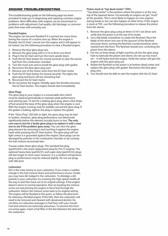
Tuning the Engine by TemperatureThe following procedures require an optional infrared temperature probe or on-board temperature gauge (such as the Traxxas on-board digital temperature gauge (part #4091). The engine can be used as an effective tuning aid when you understand the relationship between engine temperature and ambient temperature.
The engine operating temperature, when tuned for maximum performance, will vary according to atmospheric conditions. The atmospheric condition that has the most influence on engine temperature is air temperature. Expect the engine temperature to vary almost in direct proportion to atmospheric temperature. Assuming you tuned the engine for the same maximum performance each day, the engine will run about twenty degrees hotter when it’s ninety degrees outside than it would in seventy-degree weather. For this reason, we cannot give you a definitive temperature range that indicates the best possible engine tuning.
The temperature gauge can aid you in tuning by giving you a relative indication of how your adjustments are affecting the engine and by preventing you from exceeding maximum engine temperature. For example, as you lean the fuel mixture, the engine performance will increase along with the temperature. If you continue to lean the fuel mixture and the temperature increases but the engine performance does not change, then you have exceeded the maximum safe lean setting.
If tuning for maximum performance results in engine temperature exceeding 300°F, try to increase airflow to the engine by cutting out the rear of the body, windshield, and front valance. If the engine temperature still cannot be kept in check, richen the high-speed needle slightly.
the overall mixture should be...Slightly richerSlightly leanerleanerRicherRicherleanerRicherleanerRicherleaner
then the air density is...Slightly more denseSlightly less denseless denseMore denseMore denseless denseMore denseless dense
is..lowerHigherlowerHigherlowerHigherlowerHigherlowerHigher
If the...Humidity
Pressure (barometer)Temperature
altitude
Nitro %
7
Part #4091

8
ADJUSTMENTS
Toe-inGeometry and alignment specs play an important role in your truck’s handling, so take the time to set them correctly. Set the steering trim on your transmitter to neutral. Now, adjust your tie rods so that both wheels are pointing straight ahead and are parallel to each other (0 degrees toe-in). This will ensure the same amount of steering in both directions. If you run out of adjustment, then the steering servo will have to be re-centered (see “centering your servos” on page 9). For increased stability add 1-2 degrees of toe-in to each front wheel. Use the turnbuckles to adjust the alignment.
CamberThe camber angle of both the front and rear wheels can be adjusted with the camber rods (upper turnbuckles). Use a square or right-angle triangle to set the camber accurately. Adjust the front wheels to 0 degrees of camber (wheel perpendicular to the ground). In the rear, adjust the wheels to 1 to 2 degrees of negative camber. These adjustments should be set with the truck positioned at its normal ride height.
ShocksThe four shocks on Nitro Sport have the most influence on its handling. Whenever you rebuild your shocks, or make any changes to the pistons, springs or oil, always do it carefully and in pairs (front or rear). Piston selection depends on the range of oil viscosities that you have available. For example, using a two-hole piston with a lightweight oil will, at one point, give you the same damping as a three-hole piston with heavier oil. We recommend using the two-hole pistons with a range of oil viscosities from 10W to 50W (available from your hobby shop). The thinner viscosity oils (30W or less) flow more smoothly and are more consistent, while thicker oils provide more damping. Use only 100% pure silicone shock oil to prolong seal life.
The ride height for Nitro Sport can be adjusted by adding or removing the clip-on spring pre-load spacers. Instead of adding spacers to increase stiffness, use stiffer springs. Adjust the ride height so that the suspension arms are slightly above being parallel to the ground. Observe how the Nitro Sport handles in turns. If it is picking up the inside rear wheel in hard turns, then stiffen the front suspension. If it is picking up the inside front wheel in hard turns, then stiffen the rear suspension. Proper set-up will add stability and help prevent roll-overs.
Gear RatiosA unique Nitro Sport feature is the ability to change the gear ratios. The final drive ratio of the gearbox is 2.81 to 1. Use the following formula to calculate the overall ratio:
Nitro Sport comes with a 70-tooth spur gear and a 20-tooth pinion (clutch bell) gear. This combination will provide the best overall acceleration and top speed. If you want more acceleration and less top speed, then use a smaller clutch bell gear (fewer teeth). For more top speed, use a larger clutch bell gear.
adjusting the Slipper ClutchThe Nitro Sport features an adjustable slipper clutch on the spur gear to protect the drivetrain from sudden shock loads (such as landing off of jumps with the engine at full throttle). Under normal conditions the sipper clutch should not slip. Before adjusting the slipper clutch, turn the model off. Do not adjust the slipper clutch while the engine is running.
Use the supplied wrench to tighten the slipper nut (clockwise) until it stops and then back the nut out 1/4 of a turn. If you notice any decrease in performance after making changes to the slipper clutch adjustment, then it may be too loose. The slipper must not be allowed to slip during normal acceleration or the slipper could be damaged.
Changing the Clutch Bell and Spur Gears
Remove the rubber exhaust pipe and the tuned pipe. Remove the electric starter drive. Loosen the four 3x8mm cap-head screws which hold the slotted adjusting plates to the engine mount.
Remove the 4mm nylon locknut and the spring from the slipper clutch. Try to remove the slipper clutch as one assembly by holding the pressure plates together with your thumb and index finger.
PRE-lOaDSPaCERS
Remove the large E-clip on the clutch shaft and the clutch bell gear. Remove the ball bearings and install them in the new clutch bell gear. Reinstall the clutch bell gear and E-clip. Note: Smaller clutch bell gears use smaller ball bearings. Refer to your parts list for the correct bearings. Reinstall the spur gear on the top shaft and secure it with the 4mm locknut.
Slide a strip of thin note paper between the spur gear and the clutch bell gear. Push the clutch bell gear against the spur gear and tighten the 3x8mm adjusting plate screws. Remove the paper and the gear mesh should be correctly adjusted.
Pinion222222202018181616
Spur Gear667072707270727072
Final Drive8.43:18.94:19.19:19.83:1
10.11:110.92:111.24:112.27:112.64:1 aCCElERaTION
TOP SPEED
Number of Spur Gear Teeth
Number of Clutch Bell Gear Teethx 2.81 = Final Drive Ratio
0°0°
1°-2°1°-2°
-1° -1°
Toe
0°0°
1°-2°1°-2°
-1° -1°
Camber
9
MAINTENANCENitro Sport requires timely maintenance in order to stay in top running condition. Neglecting the maintenance could allow dirt, deposits, and moisture to build up inside the engine leading to internal engine failure. The following procedures should be taken very seriously.
after each hour of running:• Clean and re-oil the air filter. The instructions for this procedure are
on page 23. We cannot stress enough the value of cleaning your air filter at the scheduled intervals. The cleanliness and condition of your air filter directly influences the running life span of your engine. Do not skip air filter maintenance!
• Clean the outside of the engine of accumulated dirt, oil, and grime. Accumulated grime will decrease the engine’s ability to cool itself.
• Tighten the wheel nuts (especially on the left side).
after each running session:• Perform after-run maintenance on the engine. This clears the
engine of destructive moisture and other corrosive deposits. This is extremely important for the life of the engine.
• Inspect the gears for wear, broken teeth, or debris lodged between the teeth
• Inspect the vehicle for obvious damage or wear. Look for: 1. Loose or missing screws 2. Cracked, bent, or damaged parts 3. Cut or loose wiring 4. Cut or kinked fuel lines 5. Signs of fuel leakage
Other periodic maintenance:• Connecting rod: The connecting rod should be replaced when
the piston and sleeve are replaced. Also replace the piston wrist pin and G-clip whenever the connecting rod is replaced. As with other internal engine components, connecting rod life depends on engine’s usage and the quality and frequency of the engine maintenance. Inspect the connecting rod after three gallons of fuel have been used.
• Slipper clutch pads (friction material): The slipper clutch pegs will wear over time and require replacement. The life of the pegs depends on how the slipper clutch was adjusted and how the Nitro Sport was used. If the slipper will not tighten or you are seeing signs of wear on the face of the gear, then the pegs should be replaced.
• Piston/sleeve: The life of the piston and sleeve will vary greatly with how the engine was used and maintained. The piston and sleeve should be replaced when they no longer seal effectively (loss of compression). Symptoms include the engine being difficult to start when warm, stalling when warm, and stalling when throttle is suddenly closed to idle. Replace the wrist pin and G-clip whenever the piston and sleeve are replaced.
Centering your ServosWhenever your radio system has been removed for service or cleaning, the servos must be re-centered prior to installing the radio system in the model. If the radio system is installed in the truck, disconnect the servo horns from the servos.
Connect the steering servo to channel 1 on your receiver and the throttle servo to channel 2. The white wire on each servo cable is positioned towards the crystal. Connect the red and black cable from the battery holder to the “batt” terminal on the receiver. The red wire is positive and the black wire is negative.
Place fresh AA batteries in the transmitter and turn the power switch on. Slide the throttle and steering trim adjustments to the center position. Now install fresh AA batteries into the battery holder and turn the power switch to the “on” position. The servos will automatically jump to their center positions. Turn off the battery holder switch followed by the transmitter. The servos are now ready to be installed. Be careful not to move the servo shaft when reinstalling the servo horns.
AFTER-RUN PROCEDURE You must perform after-run maintenance on your engine whenever the model will be stored for longer than a few hours. Taking the time to prepare your engine for storage will reward you with longer engine life, easier starting, and better performance.
When a nitro engine is shut off, some excess unburned fuel remains in the engine. The methanol in model engine fuel is hydroscopic, which means it easily attracts and absorbs moisture. This moisture can cause rust and corrosion on the steel engine parts (crankshaft, bearings, wrist pin and starter shaft) if the fuel is not removed from the engine. There are after-run oil products available from your hobby dealer or you can use WD-40™, a common household lubricant. To ensure your engine is protected from internal corrosion, use the following procedure:
1. Shut off the engine by pinching the fuel line closed. This allows most of the excess fuel to be consumed by the engine. Be sure the throttle is in the idle position. You may have to pinch the fuel line closed for several seconds before the engine stops.
2. Completely empty the fuel tank. Use your fuel-dispensing bottle to suck out the old fuel. Do not mix the old fuel with your fresh fuel supply. If you leave fuel in the tank, transporting or handling your model may cause fuel to run into the engine.
3. With the fuel tank empty and the throttle at the idle position, try to start the engine. The engine will most likely start and run for a few seconds as it uses up any fuel remaining in the engine and fuel lines.
4. Once the engine stops, clean the outside of the engine with compressed air or spray motor cleaner. Once the engine is clean and dry, remove the glow plug power wire, glow plug, and air filter.
5. Open the throttle fully and spray a one-second burst of WD-40 into the carburetor and into the glow plug hole (Caution! Wear safety glasses to prevent spray from getting into your eyes). If you are using after-run oil, follow the manufacturer’s instructions.
6. Place a rag or paper towel over the engine to catch any WD-40 or after-run oil that may come out the carburetor or glow plug hole.
7. Connect the EZ-Start® controller to the model and spin the engine for 10 seconds.
8. Remove the rag or paper towel and repeat steps 5–7 two more times.
9. Clean and re-oil the air filter so it will be ready for use next time. 10. Replace the glow plug, reconnect the glow plug power wire, and
reinstall the air filter.
10
ENGINE TROUBLESHOOTING The troubleshooting guide on the following page has been provided to help you in diagnosing and repairing common engine problems. Most difficulties with engines can be traced back to problems with adjustment, fuel quality, dirt blockage, or common parts that wear with everyday use.
Flooded Engine The engine can become flooded if it is primed too many times during the course of a routine start up. When the engine is flooded, the EZ-Start® cannot turn the engine and it will appear to be locked. Use the following procedure to clear a flooded engine.
1. Remove the blue glow plug wire2. Remove the glow plug with a 5/16 or 8mm nut driver3. Plug in the EZ-Start and turn the truck upside down4. Push the EZ-Start button for several seconds to clear the excess
fuel from the combustion chamber5. Turn the truck over and re-install the glow plug with gasket6. Reconnect the blue glow plug wire7. Remove one of the motor wires from the EZ-Start motor8. Push the EZ-Start button for several seconds. This lights the
glow plug and burns off any remaining fuel9. Reconnect the EZ-Start motor10. Do not prime the engine. Partially open the throttle and press
the EZ-Start button. The engine should start immediately.
Glow Plugs The glow plug in your engine is a consumable item which must be replaced periodically to maintain peak performance and starting ease. To test for a leaking glow plug, place a few drops of fuel around the base of the glow plug when the engine is cool. With the engine running, look for bubbles around the glow plug. If the gasket is leaking, tighten the plug or replace the gasket. If the “Glow Plug” LED fails to light, the glow plug may be bad or broken. However, glow plug performance can deteriorate significantly before the element actually burns in two. The only sure way to test for a faulty glow plug is to replace it with a new one to see if the problem goes away. You can view the glow plug element by removing it and touching it against the engine head while pressing the EZ-Start button. The glow plug will not light unless it is grounded against the engine. Glow plugs can be damaged by particles in the combustion chamber or by running the fuel mixture excessively lean. Traxxas makes three glow plugs. The standard hot plug (part#3230) is the stock replacement plug for Pro.15 engines. The optional heavy-duty (part#3231) and super-duty (part#3232) plugs will last longer in most cases, however, it is a medium temperature plug so performance may be reduced slightly. Do not use plugs with idle bars!
Carburetor Dirt is the main enemy to your carburetor. If you notice a sudden change in the fuel mixture (lean) and performance of your model, you may have dirt lodged in the carburetor. To dislodge a dirt particle in your carburetor try screwing the high-speed needle all the way in and then back out to its original settings. If the engine doesn’t return to normal operation, then try backing the mixture screw out and priming the engine to force fuel through the carburetor. Return the mixture screw back to its original setting. The engine will be flooded at this point, so follow the directions for relieving a flooded engine. If this fails, then the carburetor will need to be removed and cleaned with denatured alcohol. Do not blow on carburetor passages or fuel lines with your mouth. Fuel and solvents are extremely poisonous. To prevent this from occurring again, insert a fuel filter in the line between the tank and the carburetor.
Piston stuck at “top dead center” (TDC)“Top dead center” is the position where the piston is at the very top of the tapered sleeve. Occasionally an engine can get “stuck” at this position. This is most likely to happen on new engines during break-in, but can also happen at other times. If the engine is stuck at TDC, use the following procedure to release the piston from the sleeve:
1. Remove the glow plug using an 8mm (5/16”) nut driver and verify that the piston is at the top of its stroke.
2. Use a flat blade screwdriver to rotate the flywheel. Place the blade of the driver into one of the grooves of the flywheel and push down, turning the flywheel counterclockwise when viewed from the front. The flywheel should turn, unsticking the piston from the sleeve.
3. Put two or three drops of light machine oil into the glow plug hole to lubricate the piston and sleeve. Do not use too much oil— It will hydro-lock the engine. Verify the starter will spin the engine with the glow plug out.
4. Rotate the flywheel so the piston is at bottom dead center and replace the glow plug with gasket. Reconnect the blue glow plug wire.
5. You should now be able to start the engine with the EZ-Start.
11
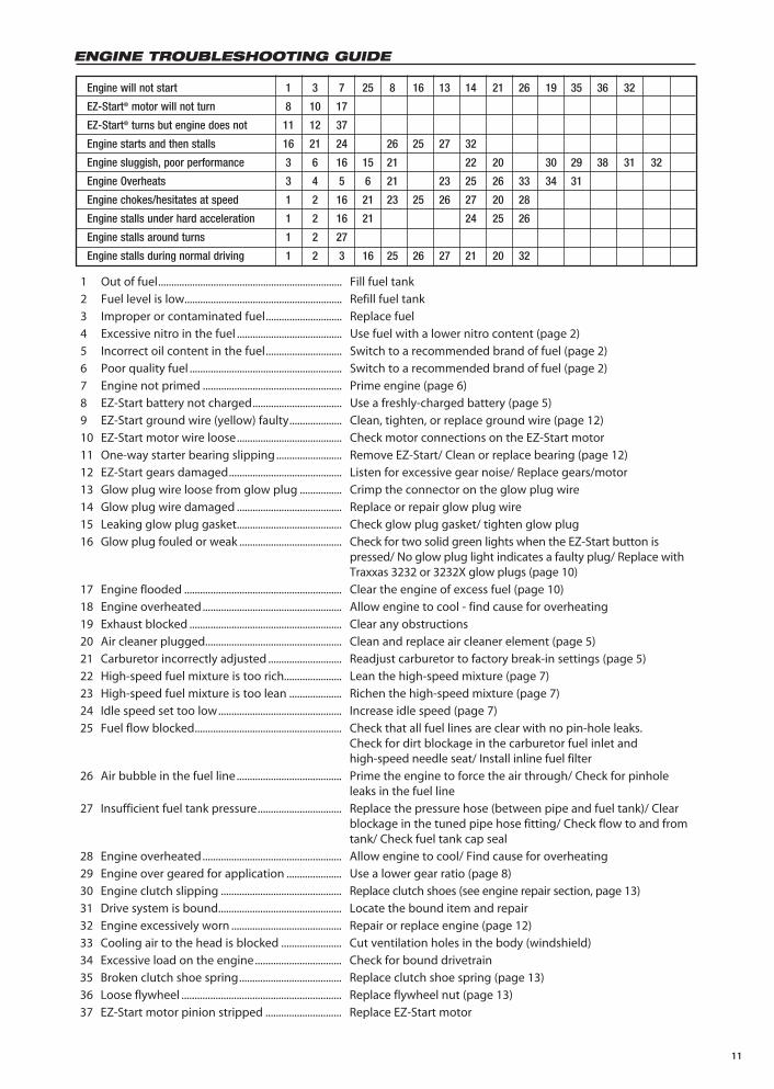
1 Out of fuel ...................................................................... Fill fuel tank
2 Fuel level is low............................................................ Refill fuel tank
3 Improper or contaminated fuel ............................. Replace fuel
4 Excessive nitro in the fuel ........................................ Use fuel with a lower nitro content (page 2)
5 Incorrect oil content in the fuel ............................. Switch to a recommended brand of fuel (page 2)
6 Poor quality fuel .......................................................... Switch to a recommended brand of fuel (page 2)
7 Engine not primed ..................................................... Prime engine (page 6)
8 EZ-Start battery not charged .................................. Use a freshly-charged battery (page 5)
9 EZ-Start ground wire (yellow) faulty .................... Clean, tighten, or replace ground wire (page 12)
10 EZ-Start motor wire loose ........................................ Check motor connections on the EZ-Start motor
11 One-way starter bearing slipping ......................... Remove EZ-Start/ Clean or replace bearing (page 12)
12 EZ-Start gears damaged ........................................... Listen for excessive gear noise/ Replace gears/motor
13 Glow plug wire loose from glow plug ................ Crimp the connector on the glow plug wire
14 Glow plug wire damaged ........................................ Replace or repair glow plug wire
15 Leaking glow plug gasket ........................................ Check glow plug gasket/ tighten glow plug
16 Glow plug fouled or weak ....................................... Check for two solid green lights when the EZ-Start button is pressed/ No glow plug light indicates a faulty plug/ Replace with Traxxas 3232 or 3232X glow plugs (page 10)
17 Engine flooded ............................................................ Clear the engine of excess fuel (page 10)
18 Engine overheated ..................................................... Allow engine to cool - find cause for overheating
19 Exhaust blocked .......................................................... Clear any obstructions
20 Air cleaner plugged .................................................... Clean and replace air cleaner element (page 5)
21 Carburetor incorrectly adjusted ............................ Readjust carburetor to factory break-in settings (page 5)
22 High-speed fuel mixture is too rich...................... Lean the high-speed mixture (page 7)
23 High-speed fuel mixture is too lean .................... Richen the high-speed mixture (page 7)
24 Idle speed set too low ............................................... Increase idle speed (page 7)
25 Fuel flow blocked ........................................................ Check that all fuel lines are clear with no pin-hole leaks. Check for dirt blockage in the carburetor fuel inlet and high-speed needle seat/ Install inline fuel filter
26 Air bubble in the fuel line ........................................ Prime the engine to force the air through/ Check for pinhole leaks in the fuel line
27 Insufficient fuel tank pressure ................................ Replace the pressure hose (between pipe and fuel tank)/ Clear blockage in the tuned pipe hose fitting/ Check flow to and from tank/ Check fuel tank cap seal
28 Engine overheated ..................................................... Allow engine to cool/ Find cause for overheating
29 Engine over geared for application ..................... Use a lower gear ratio (page 8)
30 Engine clutch slipping .............................................. Replace clutch shoes (see engine repair section, page 13)
31 Drive system is bound ............................................... Locate the bound item and repair
32 Engine excessively worn .......................................... Repair or replace engine (page 12)
33 Cooling air to the head is blocked ....................... Cut ventilation holes in the body (windshield)
34 Excessive load on the engine ................................. Check for bound drivetrain
35 Broken clutch shoe spring ....................................... Replace clutch shoe spring (page 13)
36 Loose flywheel ............................................................. Replace flywheel nut (page 13)
37 EZ-Start motor pinion stripped ............................. Replace EZ-Start motor
Engine will not start 1 3 7 25 8 16 13 14 21 26 19 35 36 32
EZ-Start® motor will not turn 8 10 17
EZ-Start® turns but engine does not 11 12 37
Engine starts and then stalls 16 21 24 26 25 27 32
Engine sluggish, poor performance 3 6 16 15 21 22 20 30 29 38 31 32
Engine Overheats 3 4 5 6 21 23 25 26 33 34 31
Engine chokes/hesitates at speed 1 2 16 21 23 25 26 27 20 28
Engine stalls under hard acceleration 1 2 16 21 24 25 26
Engine stalls around turns 1 2 27
Engine stalls during normal driving 1 2 3 16 25 26 27 21 20 32
ENGINE TROUBLESHOOTING GUIDE

12
ST
EP
7:
Rem
ove
the
3x23
mm
cap
-hea
d m
achi
ne
scre
ws
that
fa
sten
th
e he
ader
to
th
e en
gine
. C
aref
ully
rem
ove
the
head
er t
o av
oid
dam
agin
g th
e ga
sket
.T
o se
para
te t
he e
ngin
e fr
om t
he e
ngin
e m
ount
, re
mov
e th
e fo
ur 3
x8m
m c
ap-h
ead
mac
hine
scr
ews.
Reb
uild
ing
th
e E
ng
ine
ST
EP
1:
Rem
ove
the
4mm
loc
knut
fro
m t
he f
ront
pi
pe h
ange
r. P
ull
the
pipe
fro
m t
he r
ear
exha
ust
head
er.
ST
EP
2:
Unp
lug
the
blue
wire
fro
m t
he g
low
plu
g. R
emov
e th
e fu
el li
ne fr
om th
e ca
rbur
etor
inle
t and
from
the
exha
ust
head
er p
ress
ure
fittin
g. D
isco
nnec
t th
e re
d an
d bl
ack
wire
s fr
om t
he E
Z-S
tart
® m
otor
.
ST
EP
3:
Rem
ove
the
EZ
-Sta
rt g
earb
ox b
y re
mov
ing
the
thre
e 3x
8mm
rou
nd-h
ead
mac
hine
scr
ews.
ST
EP
4:
Use
a 2
.5m
m h
ex d
river
to
rem
ove
the
yello
w g
roun
d w
ire fr
om th
e en
gine
mou
nt. M
ove
the
EZ
-Sta
rt w
iring
ha
rnes
s ou
t of
the
way
.
ST
EP
5:
Use
a
2.5m
m
hex
driv
er
to
rem
ove
the
thre
e re
mai
ning
3x1
0mm
cap
-hea
d m
achi
ne s
crew
s fr
om
the
engi
ne m
ount
.
ST
EP
6:
Pul
l th
e en
gine
fro
m t
he c
hass
is.
Tur
n th
e en
gine
so
th
at
the
thro
ttle
linka
ge
to
the
carb
uret
or
will
co
me
out.
ST
EP
9:
Ch
ang
ing
th
e p
isto
n a
nd
sle
eve
asse
mb
lyU
se a
5/1
6 in
ch n
ut d
river
to r
emov
e th
e gl
ow p
lug
and
copp
er g
aske
t.
ST
EP
10:
Use
a 2
.5m
m a
llen
wre
nch
to r
emov
e th
e fo
ur 3
x12m
m
cap-
head
scr
ews
that
fas
ten
the
cylin
der
head
. R
ock
the
cylin
der
head
gen
tly f
rom
sid
e to
sid
e to
rel
ease
it
from
the
slee
ve. N
ote
the
thin
alu
min
um h
ead
gask
ets.
W
e re
com
men
d th
at y
ou r
epla
ce t
hese
gas
kets
with
ne
w o
nes
upon
rea
ssem
bly.
ST
EP
11:
Rem
ove
the
back
plat
e an
d th
e st
arte
r sh
aft.
Rep
lace
the
bac
kpla
te
gask
et
with
a
new
on
e du
ring
as
sem
bly.
ST
EP
12:
T
he p
isto
n an
d sl
eeve
are
a m
atch
ed s
et.
Whe
n th
e pi
ston
and
sle
eve
are
disa
ssem
bled
, th
ey m
ust
be
reas
sem
bled
in
the
sam
e or
ient
atio
n. U
se a
hob
by
knife
to
scra
tch
a m
ark
to i
ndic
ate
the
loca
tion
of t
he
pist
on in
rel
atio
n to
the
pin
ning
of
the
slee
ve.
ST
EP
8:
Rem
ovin
g th
e ca
rbur
etor
is
not
nece
ssar
y to
reb
uild
th
e en
gine
, un
less
you
int
end
to r
epla
ce t
he i
nter
nal
bear
ings
of
the
engi
ne.
Rem
ove
the
carb
uret
or b
y lo
osen
ing
the
3mm
lock
nut
and
pulli
ng t
he c
arbu
reto
r st
raig
ht u
p.
13
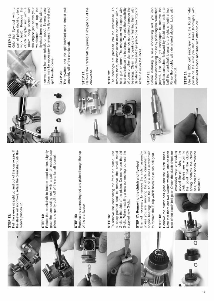
ST
EP
15:
Rem
ove
the
conn
ectin
g ro
d an
d pi
ston
thro
ugh
the
top
of t
he c
rank
case
.
ST
EP
16:
To
rem
ove
the
conn
ectin
g ro
d fr
om t
he p
isto
n, u
se
a sh
arp-
poin
ted
tool
to
re
mov
e th
e sm
all
met
al
G-c
lip in
the
sid
e of
the
pis
ton.
Do
not
re-u
se t
he o
ld
G-c
lip.
Whe
n in
stal
ling
a ne
w c
onne
ctin
g ro
d, u
se t
he
supp
lied
new
G-c
lip.
ST
EP
21:
R
emov
e th
e cr
anks
haft
by p
ullin
g it
stra
ight
out
of
the
cran
kcas
e.
ST
EP
22:
The
be
arin
gs
are
pres
s-fit
in
to
the
cran
kcas
e.
To
rem
ove
them
, th
e cr
ankc
ase
mus
t be
hea
ted
with
a
heat
gun
or
torc
h. T
he c
rank
case
will
exp
and
with
he
at a
nd r
elea
se th
e be
arin
gs. T
o av
oid
the
poss
ibili
ty
of b
urns
or
othe
r da
mag
e, d
o no
t at
tem
pt r
emov
e th
e be
arin
gs.
Cle
an t
he b
earin
gs b
y flu
shin
g th
em w
ith
dena
ture
d al
coho
l and
then
pla
ce o
ne o
r tw
o dr
ops
of
afte
r-ru
n oi
l on
the
race
s.
ST
EP
23:
Bef
ore
inst
allin
g a
new
co
nnec
ting
rod,
yo
u ca
n in
crea
se c
onne
ctin
g ro
d lif
e by
pol
ishi
ng th
e cr
anks
haft
jour
nal.
Use
12
00
grit
sand
pape
r to
re
mov
e th
e su
rfac
e sc
ratc
hes
follo
wed
by
liqui
d m
etal
pol
ish
to
buff
the
cran
ksha
ft jo
urna
l to
a b
right
, sm
ooth
shi
ne.
Rin
se t
horo
ughl
y w
ith d
enat
ured
alc
ohol
. Lu
be w
ith
afte
r-ru
n oi
l.
ST
EP
24:
Use
the
120
0 gr
it sa
ndpa
per
and
the
liqui
d m
etal
po
lish
on t
he w
rist
pin
also
. R
inse
tho
roug
hly
with
de
natu
red
alco
hol a
nd lu
be w
ith a
fter-
run
oil.
ST
EP
13:
Pul
l the
sle
eve
stra
ight
up
and
out
of t
he c
rank
case
. If
the
slee
ve w
ill n
ot m
ove,
rot
ate
the
cran
ksha
ft un
til th
e sl
eeve
pus
hes
up.
ST
EP
14:
Rot
ate
the
cran
ksha
ft to
bot
tom
dea
d ce
nter
. Li
ghtly
gr
ab t
he c
onne
ctin
g ro
d w
ith a
pai
r of
nee
dlen
ose
plie
rs a
nd g
ently
pul
l it
off
of t
he c
rank
shaf
t jo
urna
l.
ST
EP
17:
Rem
ovi
ng
th
e cl
utc
h a
nd
fly
wh
eel
It is
not
nec
essa
ry t
o re
mov
e th
e cl
utch
ass
embl
y un
less
you
are
ser
vici
ng t
he c
lutc
h, c
rank
shaf
t, or
en
gine
bea
rings
. U
se t
he t
ip o
f a
smal
l sc
rew
driv
er
to r
emov
e th
e E
-clip
whi
ch h
olds
the
clu
tch
bell
gear
.
ST
EP
18:
Rem
ove
the
clut
ch b
ell
gear
and
the
clu
tch
shoe
s.
Not
e th
at th
ere
are
two
5x8m
m w
ashe
rs, o
ne o
n ea
ch
side
of t
he c
lutc
h be
ll ge
ar. C
heck
the
clut
ch s
hoes
for
exce
ssiv
e w
ear
or c
rack
ing
arou
nd t
he p
in h
oles
. If
the
clut
ch
shoe
s ar
e w
orn
to
the
poin
t th
at
the
clut
ch
sprin
g co
ntac
ts
the
clut
ch
bell,
then
the
shoe
s m
ust b
e re
plac
ed.
ST
EP
19:
G
rip
the
flyw
heel
w
ith
a pa
ir of
plie
rs (
lock
ing
plie
rs
wor
k be
st).
R
emov
e th
e cl
utch
ad
apte
r nu
t w
ith
a 10
mm
de
ep
sock
et.
Hol
d th
e en
gine
jus
t ab
ove
your
w
orkb
ench
an
d ta
p th
e fly
whe
el f
rom
beh
ind
with
a
non-
mar
ring
ham
mer
(pl
astic
or
woo
d).
Sev
eral
eas
y bl
ows
may
be
nece
ssar
y to
rel
ease
the
fly
whe
el a
nd
split
bev
eled
con
e.
ST
EP
20:
The
fly
whe
el a
nd t
he s
plit-
beve
led
cone
sho
uld
pull
smoo
thly
off
of t
he c
rank
shaf
t.
14
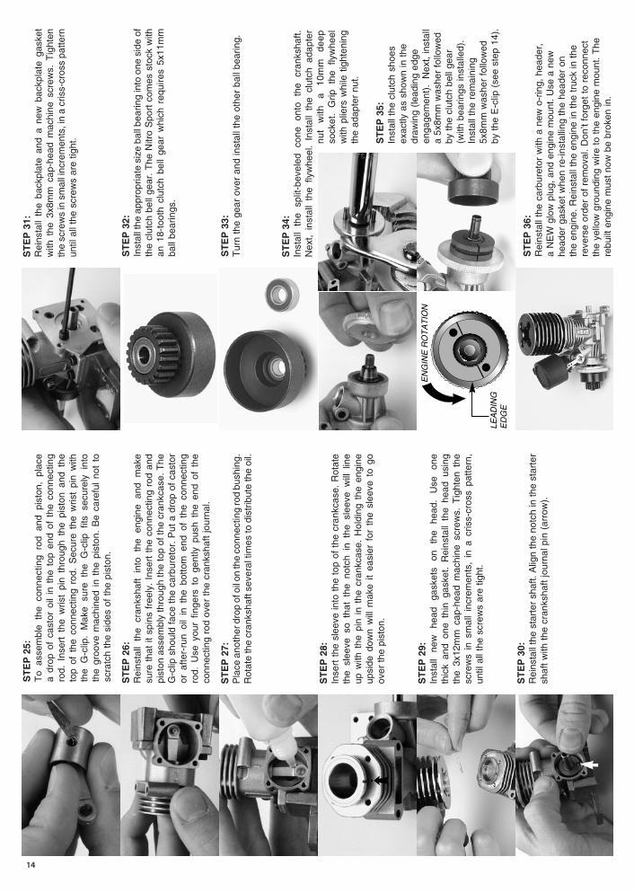
ST
EP
36:
Rei
nsta
ll th
e ca
rbur
etor
with
a n
ew o
-rin
g, h
eade
r,
a N
EW
glo
w p
lug,
and
eng
ine
mou
nt. U
se a
new
he
ader
gas
ket
whe
n re
-inst
allin
g th
e he
ader
on
the
engi
ne.
Rei
nsta
ll th
e en
gine
in t
he t
ruck
in t
he
reve
rse
orde
r of
rem
oval
. D
on’t
forg
et t
o re
conn
ect
the
yello
w g
roun
ding
wire
to
the
engi
ne m
ount
. T
he
rebu
ilt e
ngin
e m
ust
now
be
brok
en in
.
ST
EP
31:
R
eins
tall
the
back
plat
e an
d a
new
bac
kpla
te g
aske
t w
ith t
he 3
x8m
m c
ap-h
ead
mac
hine
scr
ews.
Tig
hten
th
e sc
rew
s in
sm
all i
ncre
men
ts, i
n a
cris
s-cr
oss
patte
rn
until
all
the
scre
ws
are
tight
.
ST
EP
32:
Inst
all t
he a
ppro
pria
te s
ize
ball
bear
ing
into
one
sid
e of
th
e cl
utch
bel
l gea
r. T
he N
itro
Spo
rt c
omes
sto
ck w
ith
an 1
8-to
oth
clut
ch b
ell
gear
whi
ch r
equi
res
5x11
mm
ba
ll be
arin
gs.
ST
EP
33:
T
urn
the
gear
ove
r an
d in
stal
l the
oth
er b
all b
earin
g.
ST
EP
34:
In
stal
l th
e sp
lit-b
evel
ed
cone
on
to
the
cran
ksha
ft.
Nex
t, in
stal
l th
e fly
whe
el.
Inst
all
the
clut
ch a
dapt
er
nut
with
a
10m
m
deep
so
cket
. G
rip
the
flyw
heel
w
ith p
liers
whi
le t
ight
enin
g th
e ad
apte
r nu
t.
ST
EP
35:
Inst
all t
he c
lutc
h sh
oes
exac
tly a
s sh
own
in t
he
draw
ing
(lead
ing
edge
en
gage
men
t).
Nex
t, in
stal
l a
5x8m
m w
ashe
r fo
llow
ed
by t
he c
lutc
h be
ll ge
ar
(with
bea
rings
inst
alle
d).
Inst
all t
he r
emai
ning
5x
8mm
was
her
follo
wed
by
the
E-c
lip (
see
step
14)
.
ST
EP
25:
To
asse
mbl
e th
e co
nnec
ting
rod
and
pist
on,
plac
e a
drop
of
cast
or o
il in
the
top
end
of
the
conn
ectin
g ro
d. I
nser
t th
e w
rist
pin
thro
ugh
the
pist
on a
nd t
he
top
of t
he c
onne
ctin
g ro
d. S
ecur
e th
e w
rist
pin
with
th
e G
-clip
. M
ake
sure
the
G-c
lip f
its s
ecur
ely
into
th
e gr
oove
mac
hine
d in
the
pis
ton.
Be
care
ful
not
to
scra
tch
the
side
s of
the
pis
ton.
ST
EP
26:
Rei
nsta
ll th
e cr
anks
haft
into
th
e en
gine
an
d m
ake
sure
tha
t it
spin
s fr
eely
. In
sert
the
con
nect
ing
rod
and
pist
on a
ssem
bly
thro
ugh
the
top
of th
e cr
ankc
ase.
The
G
-clip
sho
uld
face
the
car
bure
tor.
Put
a d
rop
of c
asto
r or
afte
r-ru
n oi
l in
the
bot
tom
end
of
the
conn
ectin
g ro
d. U
se y
our
finge
rs t
o ge
ntly
pus
h th
e en
d of
the
co
nnec
ting
rod
over
the
cra
nksh
aft
jour
nal.
ST
EP
27:
Pla
ce a
noth
er d
rop
of o
il on
the
conn
ectin
g ro
d bu
shin
g.
Rot
ate
the
cran
ksha
ft se
vera
l tim
es to
dis
trib
ute
the
oil.
ST
EP
28:
In
sert
the
sle
eve
into
the
top
of
the
cran
kcas
e. R
otat
e th
e sl
eeve
so
that
the
not
ch i
n th
e sl
eeve
will
lin
e up
with
the
pin
in
the
cran
kcas
e. H
oldi
ng t
he e
ngin
e up
side
dow
n w
ill m
ake
it ea
sier
for
the
sle
eve
to g
o ov
er t
he p
isto
n.
ST
EP
29:
In
stal
l ne
w
head
ga
sket
s on
th
e he
ad.
Use
on
e th
ick
and
one
thin
gas
ket.
Rei
nsta
ll th
e he
ad u
sing
th
e 3x
12m
m c
ap-h
ead
mac
hine
scr
ews.
Tig
hten
the
sc
rew
s in
sm
all
incr
emen
ts,
in a
cris
s-cr
oss
patte
rn,
until
all
the
scre
ws
are
tight
.
ST
EP
30:
Rei
nsta
ll th
e st
arte
r sh
aft.
Alig
n th
e no
tch
in th
e st
arte
r sh
aft
with
the
cra
nksh
aft
jour
nal p
in (
arro
w).