Coverage Tutorial Using the Object Model -...
23
Analytical Graphics, Inc. (AGI) 1 of 23 Object Model Tutorial for Coverage Coverage Tutorial Using the Object Model This tutorial shows how to use the STK Object Model to set up a simple coverage analysis, performing tasks for which you might otherwise use Connect or the STK GUI. Source code is given in C# and Visual Basic.NET. Familiarity with Microsoft Visual Studio and STK are presumed. Source Code Location: The source code for this tutorial is in the following text file: <STK Install Folder>\Help\LinkedDocuments\OM_CoverageTutorial.txt The code is broken into sections corresponding to the sections in this tutorial. Within each section, the C# and VB.NET code are presented in separate subsections. CONTENTS Where to Get Help .............................................................................................................. 1 Start Visual Studio and Create your Project ............................................... 3 Add STK X Controls to your Form ............................................................ 4 Set the Scene for the Coverage Analysis ............................................................................ 6 Add the Core of the STK Object Model to your Project ............................ 6 Create and Populate a Scenario................................................................... 6 Animate the Scenario .................................................................................. 7 Coverage with the Object Model ........................................................................................ 8 Create a Coverage Definition...................................................................... 8 Set Coverage Bounds .................................................................................. 9 Set Coverage Resolution ........................................................................... 11 Compute Coverage.................................................................................... 12 Define Figure of Merit .............................................................................. 15 Set Satisfaction Criterion .......................................................................... 19 Display Coverage Contours ...................................................................... 21 Where to Get Help Before proceeding with this tutorial, take a moment to familiarize yourself with the parts of the STK Programming Interface Help system that relate to the Object Model and STK X. In the Contents tab of the Help system, navigate to Using Core Libraries STK Object Model STK Objects.
Transcript of Coverage Tutorial Using the Object Model -...

Analytical Graphics, Inc. (AGI) 1 of 23 Object Model Tutorial for Coverage
Coverage Tutorial Using the Object Model This tutorial shows how to use the STK Object Model to set up a simple coverage analysis, performing tasks for which you might otherwise use Connect or the STK GUI. Source code is given in C# and Visual Basic.NET. Familiarity with Microsoft Visual Studio and STK are presumed. Source Code Location: The source code for this tutorial is in the following text file: <STK Install Folder>\Help\LinkedDocuments\OM_CoverageTutorial.txt The code is broken into sections corresponding to the sections in this tutorial. Within each section, the C# and VB.NET code are presented in separate subsections.
CONTENTS Where to Get Help .............................................................................................................. 1
Start Visual Studio and Create your Project ............................................... 3 Add STK X Controls to your Form ............................................................ 4
Set the Scene for the Coverage Analysis ............................................................................ 6 Add the Core of the STK Object Model to your Project ............................ 6 Create and Populate a Scenario................................................................... 6 Animate the Scenario .................................................................................. 7
Coverage with the Object Model ........................................................................................ 8 Create a Coverage Definition...................................................................... 8 Set Coverage Bounds .................................................................................. 9 Set Coverage Resolution ........................................................................... 11 Compute Coverage.................................................................................... 12 Define Figure of Merit .............................................................................. 15 Set Satisfaction Criterion .......................................................................... 19 Display Coverage Contours ...................................................................... 21
Where to Get Help Before proceeding with this tutorial, take a moment to familiarize yourself with the parts of the STK Programming Interface Help system that relate to the Object Model and STK X. In the Contents tab of the Help system, navigate to Using Core Libraries STK Object Model STK Objects.

Analytical Graphics, Inc. (AGI) 2 of 23 Object Model Tutorial for Coverage
In addition to these introductory sections, the Library Reference for STK Objects is broken down into subsections for the various types in the library.
Try this: To find help for the AgStkObjectRoot class discussed above, click Library ReferenceSTK Object ModelSTK Objects and scroll down the alphabetical list until you find the entry entitled "AgStkObjectRoot". Click AgStkObjectRoot to display a page containing a diagram with several links, including a link to Root (IAgStkObjectRoot Object). From that page you can access a page that lists all the members (methods and properties) of the interface associated with the AgStkObjectRoot object. Similarly, you can find help for any other object or interface, as well as any method, property or enumeration.

Analytical Graphics, Inc. (AGI) 3 of 23 Object Model Tutorial for Coverage
A quick way to find help on a given type is to use the Search tab of the Help system. For example, suppose you are interested in the AgECoordinateSystem enum. If you enter "AgECoordinateSystem" in the search field and click List Topics, a list of pages containing that term appears. Click on the Title heading to order the list alphabetically, and the entry for AgECoordinateSystem will appear at the top. Click that entry to display a page defining the enum and listing its members.
TIP: Keep the STK Programming Interface Help system open to the Search tab while you are working through this tutorial. Then you can copy and paste the names of interfaces, enumerations, etc. into the search field to learn more about their meaning and usage.
NOTE: It is not necessary to have STK running to display the Help system. To launch Help, simply open the Windows Start Menu and navigate to to All Programs STK 11 Help STK 11 – Programming Interface.
In addition to the Object Model (STK Objects and STK Util), you may find it useful to refer to help on STK X controls.
One final note on the STK Programming Interface help: In addition to help on programming issues, the help provides information about the real-world context in which the application is to be used. For example, the help page for the SpinAxisConeAngle property tells you that it is writable, is of the Variant data type, and belongs to the IAgSnPtSpinning interface. In addition, it tells you that the property represents "the cone angle used in defining the spin axis; i.e., the angle between the spin axis and the sensor boresight." This latter information is useful in deciding whether and how to use the property in your application, but it is necessarily somewhat sketchy, since the help is mainly intended to provide guidance on programming issues. However, in the STK Help System, there is generally more information. For example, the help page for “Spinning Sensor Pointing” not only gives more detailed context information but also includes a drawing of spin axis geometry that illustrates the spin axis cone angle quite clearly.
TIP: For real-world context information on the Object Model types that you use in your application, do not rely solely on the brief definitions in the Object Model help. Refer also to the STK Help System.
Start Visual Studio and Create your Project You will use two STK X controls for this tutorial. To add these controls and to use the STK Object Model, you must add the following COM references to your project:
STK Objects – a COM Library containing types, interfaces, events and classes representing various aspects of the STK application structure.
STK Util – a library containing objects and enumerations shared by the STK Objects and STK X type libraries.
STK X - a collection of COM components and ActiveX controls that use STK Engine technology.

Analytical Graphics, Inc. (AGI) 4 of 23 Object Model Tutorial for Coverage
Here are the steps to set up your project and add the necessary references: 1. Start Visual Studio and click on TFileT and then New TProjectT. 2. Under the TInstalledT templates, navigate to Templates, select either Visual Basic or
C#, then in the Windows page choose TWindows Forms ApplicationT. Configure the rest of your project settings as you see fit. In this tutorial, CoverageTutorialT is used as the project name.
3. Once your new project has loaded, open the Solution Explorer in the View tab, right-click on the project name, and then select Properties.
4. Click on the Build tab in the properties panel if using C#. Go to the Compile tab for Visual Basic
5. For C#, in the Platform target field, select “x86”, and then close the properties panel. For Visual Basic, in the Target CPU field, select “x86”, and then close the properties panel.
6. Finally, click on the TProjectT menu and select the TAdd Reference…T menu item. Select the TCOMT tab and add the following references to your project:
AGI STK Objects 11 AGI STK Util 11 AGI STK X 11
Add STK X Controls to your Form Before you begin writing Object Model code, use the design view in Visual Studio to draw the user interface for your custom application. When you are finished, the GUI you create will look something like this:

Analytical Graphics, Inc. (AGI) 5 of 23 Object Model Tutorial for Coverage
The application that you create allows the user to:
Create a Scenario and display it in 2D and 3D windows. Control the animation of the scenario. Select various actions from a combo box: define a coverage region, compute
coverage, select a figure of merit and display the quality of coverage graphically in the 2D and 3D windows.
Here are the steps to create the GUI:
1. Display the automatically-generated TForm1T in design view and stretch the form so that it is approximately square and substantially fills the available workspace (with Visual Studio maximized). Display its properties page and change the TText Tproperty from “Form1” to “Coverage with the STK Object Model”.
2. If the Toolbox is not already in your workspace, then add it by clicking on TViewToolboxT from the menu. Right-click on a blank area in the General section of the toolbox (i.e., neither a control nor the Toolbox title bar), and select TChoose Items…T from the drop-down menu.
3. From the dialog, select the TCOM ComponentsT tab and add the following components to your project by selecting the checkboxes next to their entries:
AGI Globe Control 11 AGI Map Control 11
4. Click TOKT to close the dialog. 5. From the Form1T design view, find TAGI Globe Control 11 in the Toolbox, and
draw a rectangular shape in the upper left region of your form. Do the same thing with the AGI Map Control 11 in the lower left region of the form.
6. Place a ComboBox in the upper right corner of the form. 7. Display the properties page for the ComboBox, change its Text property to
"Select Action…". Afterwards, set the Enabled property to False – the code in the .txt file will enable this after a new scenario is created.
8. Place a button below the ComboBox and change its Text property to "New Scenario".
9. Place a GroupBox below the "New Scenario" button and stretch it so that it will accommodate 6 buttons, arranged vertically. Change its Text property to "Animation".
10. Arrange 6 buttons vertically in the GroupBox. Set the Enabled property for all of the buttons to False. Starting with the top button and working down, set the Text properties of the buttons to: Play Scenario Pause Scenario Reset Scenario Play Backward Slower Faster

Analytical Graphics, Inc. (AGI) 6 of 23 Object Model Tutorial for Coverage
This completes the artistic part of this exercise. Now, on to coding with the Object Model.
Set the Scene for the Coverage Analysis
Add the Core of the STK Object Model to your Project Refer to OM_CoverageTutorial.txt for the code segments to be added in this section. Begin by adding statements at the beginning of the code (using in C#, Imports in VB.NET) to gain access to the types defined in the STK Objects and STK Util libraries. Next, define and initialize an instance of AgStkObjectRoot, the top level object in the Object Model hierarchy, which exposes a set of methods and properties that you will find indispensable in implementing the Object Model in your application. To name just 3 examples, this class includes the following methods:
NewScenario(): creates a new STK scenario. LoadScenario(): loads a scenario file on a specified path. ExecuteCommand(): takes a string representing a Connect command as an
argument and executes the command.
Finally, add the OnFormClosing method to close STK Object root properly, as indicated in OM_CoverageTutorial.txt.
Create and Populate a Scenario Referring to OM_CoverageTutorial.txt, add a function to create a new scenario to the main body of the Form1 class and populate it with two satellites. Then add a call to that function to the Click event for button you created. At this point you should be able to build and run your application. Click the button to display the 3D Globe and 2D Map:

Analytical Graphics, Inc. (AGI) 7 of 23 Object Model Tutorial for Coverage
More detailed discussion of the interfaces, methods and properties made available by the Object Model for creating and configuring satellites can be found in STK Tutorial Using the Object Model.
Animate the Scenario Add the appropriate method of the AgStkObjectRoot object to the appropriate Click method of each of the animation buttons that you drew on Form1:
TButton text TCode in Click methodT
Play Scenario root.PlayForward()
Pause Scenario root.Pause()
Reset Scenario root.Rewind()
Play Backward root.PlayBackward()
Slower root.Slower()
Faster root.Faster()
If you are coding in C#, of course, you need to add a semicolon (;) to each of those method statements. Build and run the application, create a scenario, experiment with the animation controls, and observe the results in your 2D and 3D displays.

Analytical Graphics, Inc. (AGI) 8 of 23 Object Model Tutorial for Coverage
Coverage with the Object Model
Create a Coverage Definition In the STK GUI, a coverage grid is defined using the coverage definition's BasicGrid page. Here, for example, using Latitude Bounds, a grid is defined to cover a tropical region (between 23.5 deg north and south of the Equator), with a resolution of 3 deg between grid points:
In this exercise we have broken the process of creating a coverage definition, defining its bounds and setting its resolution into three methods, so that we can see the effect of each separately. Referring to OM_CoverageTutorial.txt, the coverage definition is created with a single line of code, invoking the New method of the IAgStkObjectCollection interface, which takes as arguments an enumeration member representing the class of the new object (in this case AgESTKObjectType.eCoverageDefinition) and an instance name ("Tropics"). The Children property is used to indicate that the new object is a child of the current scenario. A variable representing the coverage definition needs to be added to the Form1 class, where it will be available for use by other methods in that class. At this juncture, you will also add (to the Form1 class constructor) the code needed to populate the combo box. Finally, you will add to the SelectedIndexChanged method of the combo box a call to the CreateCovDef() method.
NOTE: The SelectedIndexChanged() method includes calls to the BeginUpdate() and EndUpdate() methods of the AgStkObjectRoot class. The BeginUpdate() method suspends graphic updates, which helps speed up processing of a block of code. The graphic updates are then carried out in a batch when you invoke EndUpdate().

Analytical Graphics, Inc. (AGI) 9 of 23 Object Model Tutorial for Coverage
Now build and run the application, create a scenario, and select Create Coverage Definition from the combo box:
Set Coverage Bounds The CoverageBounds() method gets the reference to the IAgCvGrid interface from the coverage definition's Grid property, then it configures the IAgCvBoundsLat interface of the Bounds property of IAgCvGrid. Latitude bounds are then set using the MaxLatitude and MinLatitude properties of IAgCvBoundsLat.

Analytical Graphics, Inc. (AGI) 10 of 23 Object Model Tutorial for Coverage
Again, add a variable to the Form1 class and update the SelectedIndexChanged() method. Now build and run the application, create a scenario, and select Create Coverage Definition and Set Coverage Bounds from the combo box:

Analytical Graphics, Inc. (AGI) 11 of 23 Object Model Tutorial for Coverage
Set Coverage Resolution The CoverageResolution() method uses only one interface, IAgCvResolutionLatLon, which is initialized to the Resolution property of the IAgCvGrid instance that was introduced with our CoverageBounds() method. (This is why you had to declare the variable representing that instance at the Form1 level.)
Using the LatLon property of IAgCvResolutionLatLon, set the resolution to 3 deg. After updating the SelectedIndexChanged() method, build and run the scenario, and select Create Coverage Definition, Set Coverage Bounds and Set Coverage Resolution from the combo box:

Analytical Graphics, Inc. (AGI) 12 of 23 Object Model Tutorial for Coverage
Compute Coverage The ComputeCoverage() method carries out the actual computation of coverage in a single line, but that line is preceded by code to assign the coverage assets and configure graphics properties. In the STK GUI, the coverage definition's Basic – Assets page lets you assign the coverage assets (in this case, the two satellites) and set their Status (active or inactive), among other things:
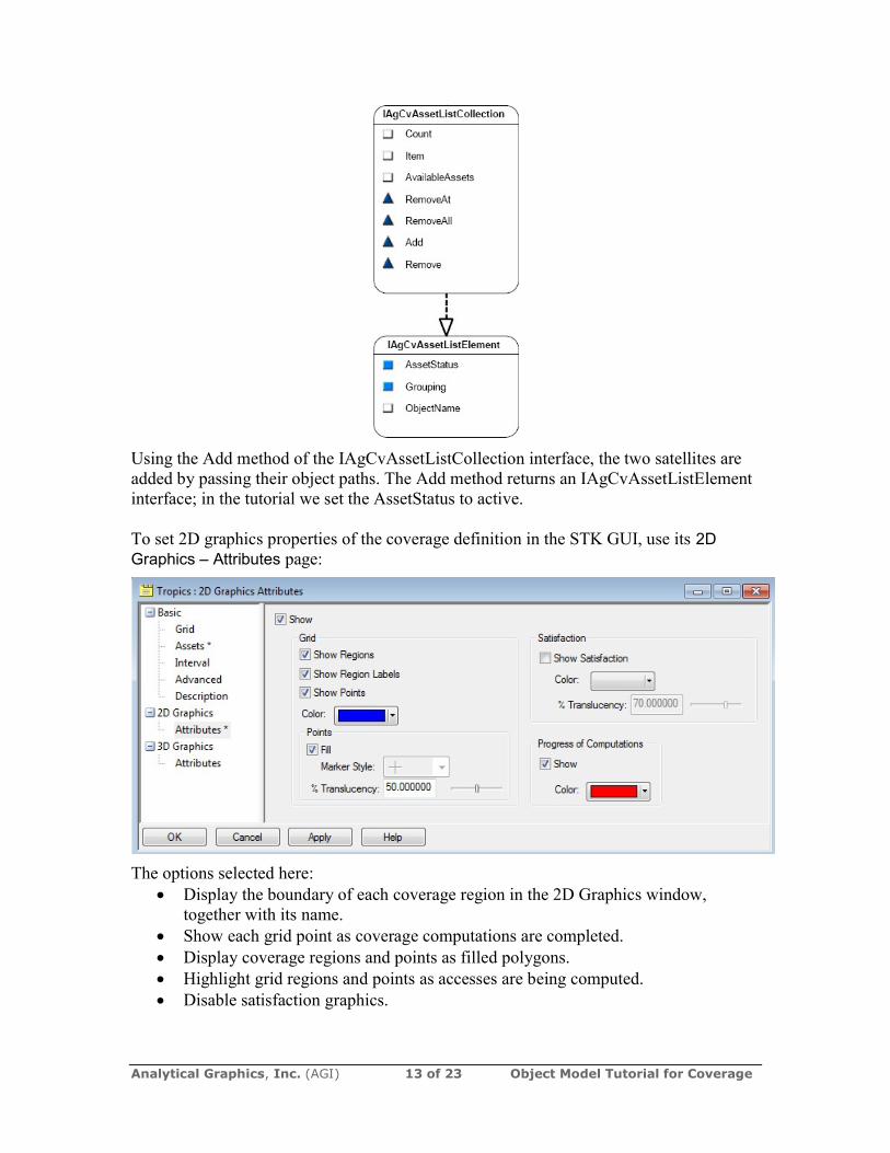
In the Object Model, the above assignment uses the IAgCvAssetListCollection interface, which is retrieved from the coverage definition's AssetList property.
Analytical Graphics, Inc. (AGI) 13 of 23 Object Model Tutorial for Coverage
Using the Add method of the IAgCvAssetListCollection interface, the two satellites are added by passing their object paths. The Add method returns an IAgCvAssetListElement interface; in the tutorial we set the AssetStatus to active. To set 2D graphics properties of the coverage definition in the STK GUI, use its 2D Graphics – Attributes page:
The options selected here: Display the boundary of each coverage region in the 2D Graphics window,
together with its name. Show each grid point as coverage computations are completed. Display coverage regions and points as filled polygons. Highlight grid regions and points as accesses are being computed. Disable satisfaction graphics.

Analytical Graphics, Inc. (AGI) 14 of 23 Object Model Tutorial for Coverage
The Object Model provides a hierarchy of interfaces under the coverage definition's Graphics property to let you make the above settings:
The IAgCvGfxStatic interface lets you set the region, label, point and fill display options.
The IAgCvGfxProgress interface lets you set the options related to progress of computations.
The IAgCvGfxAnimation interface lets you configure satisfaction graphics. After these settings are made, invoke the coverage definition's ComputeAccesses() method, corresponding to the Compute Accesses option in the coverage definition's tools menu in the GUI. After updating the SelectedIndexChanged() method, build and run the application, then select Create Coverage Definition, Set Coverage Bounds, Set Coverage Resolution and Compute Coverage from the combo box:

Analytical Graphics, Inc. (AGI) 15 of 23 Object Model Tutorial for Coverage
Define Figure of Merit In the STK GUI, after creating a figure of merit object as a child of the coverage definition object, you can use its Basic – Definition page to select the type of figure of merit you want and to set its Compute option:
Here N Asset Coverage is selected, which measures the number of assets available simultaneously during coverage, with the Maximum Compute option; i.e., the maximum number of assets available over the entire coverage interval.

Analytical Graphics, Inc. (AGI) 16 of 23 Object Model Tutorial for Coverage
In the Object model, the figure of merit object provides a SetDefinitionType() method for selecting the type of figure of merit, and an interface available via its Definition property lets you set the compute type:
In the STK GUI, to configure the display of the figure of merit in the 2D Graphics window, use its 2D Graphics – Animation and Static pages:

Analytical Graphics, Inc. (AGI) 17 of 23 Object Model Tutorial for Coverage
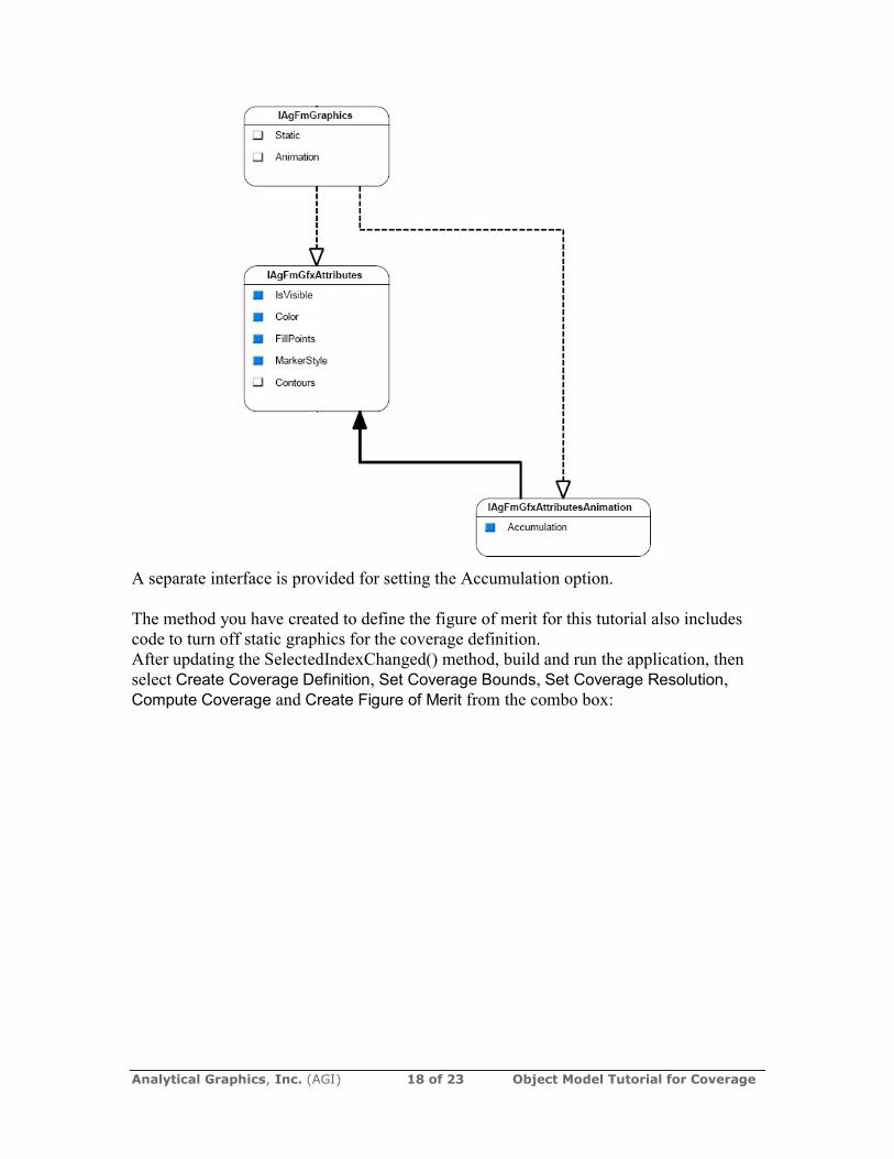
Among other things, options were selected to use markers instead of fill for static and animation graphics, and use Current Time as the Accumulation option; i.e., when animating, only grid points that currently meet the satisfaction criterion are highlighted. In the Object Model, most of the above settings are made using the IAgFmGfxAttributes interface, which is instantiated first to the Static then to the Animation property of the IAgFmGraphics interface:
Analytical Graphics, Inc. (AGI) 18 of 23 Object Model Tutorial for Coverage
A separate interface is provided for setting the Accumulation option. The method you have created to define the figure of merit for this tutorial also includes code to turn off static graphics for the coverage definition. After updating the SelectedIndexChanged() method, build and run the application, then select Create Coverage Definition, Set Coverage Bounds, Set Coverage Resolution, Compute Coverage and Create Figure of Merit from the combo box:
Analytical Graphics, Inc. (AGI) 19 of 23 Object Model Tutorial for Coverage
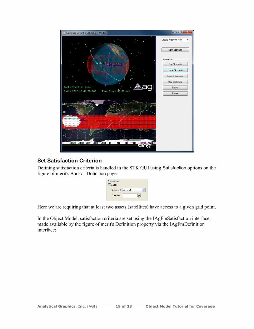
Set Satisfaction Criterion Defining satisfaction criteria is handled in the STK GUI using Satisfaction options on the figure of merit's Basic – Definition page:
Here we are requiring that at least two assets (satellites) have access to a given grid point. In the Object Model, satisfaction criteria are set using the IAgFmSatisfaction interface, made available by the figure of merit's Definition property via the IAgFmDefinition interface:

Analytical Graphics, Inc. (AGI) 20 of 23 Object Model Tutorial for Coverage
After updating the SelectedIndexChanged() method, build and run the scenario, then select Create Coverage Definition, Set Coverage Bounds, Set Coverage Resolution, Compute Coverage, Create Figure of Merit and At Least Two from the combo box:

Analytical Graphics, Inc. (AGI) 21 of 23 Object Model Tutorial for Coverage
`
Display Coverage Contours In the STK GUI, to set up animation contours to show the degree of satisfaction of the figure of merit (by one or both assets) dynamically, use its 2D Graphics – Animation page:

Analytical Graphics, Inc. (AGI) 22 of 23 Object Model Tutorial for Coverage
Here we have opted to show animation contours and have used the Explicit color method to assign a color to each level of satisfaction of the figure of merit (by one or both satellites). In the Object Model, use the IAgFmGfxContours interface and two interfaces that it makes available to set the above options:
The IAgFmGfxContours interface is available via the Contours property of the IAgFmGfxAttributes interface The method used in this tutorial to set up animation contours first turns off the figure of merit's static graphics, then leverages the above interfaces to turn on animation contours, add two contour levels and assign a color to each. After updating the SelectedIndexChanged() method, build and run the scenario, then select Create Coverage Definition, Set Coverage Bounds, Set Coverage Resolution, Compute Coverage, Create Figure of Merit, At Least Two and Contours from the combo box. Then animate the scenario and watch the changing graphics display in the 2D and 3D windows:

Analytical Graphics, Inc. (AGI) 23 of 23 Object Model Tutorial for Coverage