cover NF MCCB - KVC Industrial Supplies Sdn Bhd … · NF MCCB Based on Mitsubishi MCCB Datasheet....
77
Issued November 2009 12485 DATA SHEET NF MCCB Based on Mitsubishi MCCB Datasheet
Transcript of cover NF MCCB - KVC Industrial Supplies Sdn Bhd … · NF MCCB Based on Mitsubishi MCCB Datasheet....

Issued November 2009 12485
DATA SHEET
NF MCCB
Based on Mitsubishi MCCB Datasheet

SeriesFrame Size
Photo
Type name
Rated current In (Amp.)
Rated ambient temperature (°C)Number of polesRated insulation voltage Ui (V)
Ratedshort-circuitbreakingcapacities (kA)
IEC60947-2(Icu/Ics)
AC(50/60Hz)
690V525V500V440V415V400V380V
DC
230V250V300V
Utilization categoryReverse connection (terminals unmarked)Rated impulse withstand voltage Uimp (kV)Pollution degree
Number of operating cycles
without current
with current
440V-In/2440V-In690V-In/2690V-In
Overall dimensions (mm)
abcca
Installationandconnections
FixedFront
Screw terminal
Synchronous Closing (UVT-S)Non-Synchronous Closing (UVT-N)
Solderless (box) terminal (SL)
Rear (B)Busbar terminal
Plug-inRear (PM)Rear/front IP20 (PM-IP)
IEC 35mm rail
Mounting hook (option)Adapter (option)
Cassette-typeaccessories(option) ✽ 5
Alarm switch (AL)Auxiliary switch (AX)Shunt trip (SHT)
Undervoltage trip (UVT)
Accessorie’s connection(option)
with Lead-wire terminal block (SLT)with Internal terminal type (INT)with Flying leads
Built-inaccessories(option)
Pre-alarm (contact output) ✽ 3 (PAL)Overcurrent trip alarm ✽ 3 (OAL)
EnclosureDustproof
(S) ( I )
Handle lock (HL)
(HL-S)
Externalaccessories(option)
Marine approval
Electrical operation device (MD) Mechanical interlock
Handle lock device
(MI)
Lock cover (LC)
Waterproof (W)
Externaloperatinghandle
Door mounting (V)(S)
Mounted on breaker(R)(F)
Insulatingbarrier
Between phase (BA-F)To ground (BA-G)
Terminalcover
Large (TC-L)Small (TC-S)
for rear connection (BTC)for plug-in (PTC)
L/RG/LBV
DNVABS
Automatic tripping device
Trip button
Notes ✽ 1: Use two poles in the case of three-pole or four-pole products.In addition, wiring as shown to the right allows the three poles to be used for up to 400V DC and the four poles to be used for up to 500V DC.
✽ 2: Use two poles in the case of three-pole or four-pole products.In addition, wiring as shown to the right allows the three poles to be used for up to 500V DC and the four poles to be used for up to 600V DC.
✽ 3: Both PAL and OAL is not available. Only one specified.✽ 4: Specify if for DC use.✽ 5: Cassette-type accessories are not suitable for NF30-CS.
a cac
b
Suitability for isolation
Mass of front-face type (kg)
Transparent (TTC)
Cylinder key lock
Available soon
Available soon
C series30
NF30-CS
3 5 1015 20 30
302 3
45 67.5
500–––
–1.5/1.5
–
1.5/1.52.5/2 (240V)
––
–
A–42
10,0006,000 (415V)
––
965267
––
–––●
–––
–
––
–
––
–●–
––––––
–
–––
Hydraulic-magnetic
–
0.25 0.35
–
●
●
●●
●
●
●
●
●●
●
●
●
●
6,000 (415V)
S series C series C seriesS series32
NF32-SW
3 4 6 10 1620 25 32
402 3
2.5/1 ✽ 4 –
600––
2.5/12.5/12.5/15/25/2
7.5/4
–
A
62
10,0006,0006,000
––
1306890
––
–
–
–
–
––
–
–
Hydraulic-magneticEquipped
50 75
–
–
0.4 0.55
●
●
●
●●
●
●●●●
●
●
●●
●●●●
●
●●●●●
●●●●●●●
●
●
●
–
63
NF63-CW
3 4 6 10 16 2025 32 40 50 63
402 3
2.5/1 ✽ 4 –
50 75
600––
2.5/12.5/12.5/15/25/2
7.5/4
–
A
62
10,0006,0006,000
––
1306890
––
–
–
–
–
––
–
–
Hydraulic-magneticEquipped
–
–
0.45 0.6
–
●
●
●
●●
●
●●●●
●
●
●●
●●●●
●
●●●●●
●●●●●●●
●
●
●
63
NF63-SW
3 4 6 10 16 2025 32 40 50 63
402 3 4
600––
7.5/47.5/47.5/47.5/47.5/415/8
–
A
62
15,00015,0008,000
––
1306890
––
–
–
–
–
––
–
–
Hydraulic-magneticEquipped
7.5/4 ✽ 4 –
50 75 100
0.45 0.6 0.7
––––
–––––
–
●
●
●
●●
●
●●●●
●
●
●●●●
●
●●●●●
●●
●
●●
●
●●●●●
●
–
●●●●●
●●●
●
●
●●●●
●
●●
●
●
●
●
●
●●
●●●●●
●
●●●●
H series63
NF63-HW
10 16 20 25 32 40 50 63
40
6902.5/1
–7.5/410/510/510/510/525/13
–
A
62
15,00015,0008,000
–-–
1306890
––
–
–
–
–
––
–
–
Hydraulic-magneticEquipped
7.5/4 ✽ 4 –
50 75 100
0.45 0.6 0.7
––––
–––––
–
432
–
125
NF125-CW
50 63 80100 125
402 3
7.5/4 ✽ 1
60 90
600––
7.5/410/510/510/510/530/15
–
A
83
10,0006,0006,000
––
1306890
–
––
–
––
Thermal-magneticEquipped
0.65 0.9
––
–
●
●
●●
●●
●●●●●●●
●
●●
●●●●
●●●●●●●
●●●●●●●
●●
●
●
●
3-pole 4-pole
Line
Load Load
Line
Detailed SpecificationsMolded-Case Circuit Breakers
12485
Based on Mitsubishi MCCB Datasheet Page 1 of 76
2
●●●●●
●
●
●●●●●●
●
●●
●●
●
●
●●●
●
●
●
●●
●●●●●●●
●●●●
S series
NF125-SW
16 20 32 40 50 63 80 100 125
40
6908/418/518/925/1330/1530/1530/1550/25
–
A
83
25,00020,00010,0001,0001,000
1306890
–
––
–
––
Thermal-magneticEquipped
125
15/8 ✽ 1
60
0.7
90 120
0.95 1.3
––
–––
–––––
–
432
–
●●●●
●●●●
●●
●●
●●●●●●●●
●●●
●
●
●●
●
●
●●●●
●●●
●
●
●●
●
●
●●
●●
●
●●
●●
●●●
●●●●●
●●
●●
●●●
●●●●●●
NF125-SGWRT
16–25 25–40 40–63 63–100 80–125
40
–
6908/8
22/2230/3036/3636/3636/3636/3685/85
A
83
50,00040,00030,0001,0001,000
16586110
–
–
––
–
––
– –
–
–
Thermal-magneticEquipped
NF125-SGWRE
16–32 32–63 63–100 75–125
403 4
6908/8
22/2230/3036/3636/3636/3636/3685/85
––
A
83
50,00040,00030,0001,0001,000
16586110
–
–
––
–
–
–
Electronic
Equipped
105 140
2.0 2.6
105 140
2.0 2.6
––
––
432
20/20 ✽ 2
●●●●●
●●●
●
●
●●●●●●
●
●●
●●
●
●
●
●
●
●●
●●●●●●●
●●●●
NF125-HW
16 20 32 40 50 63 80 100
40
69010/522/1130/1550/2550/2550/2550/25100/50
–
A
83
25,00020,00010,0001,0001,000
1306890
–
––
–
––
Thermal-magneticEquipped
40/20 ✽ 1
0.8 0.95
90 120
1.3
––
–––
–––––
–
432
–
●●●●
●●●●
●●
●●
●●●●●●●●
●●●
●
●
●●
●
●
●●●●
●●●
●
●
●●
●
●
● ●
●●
●●
●●
●●
●●●
●●●●●
●●
●●
●●●
●●●●●
H series
–
Electronic
125
NF125-HGWRT
16–25 25–40 40–63 63–100 80–125
40
69020/2035/3550/5065/6570/7075/7575/75
100/100
A
83
50,00040,00030,0001,0001,000
16586110
–
–
––
–
––
●
–
Thermal-magneticEquipped
NF125-HGWRE
16–32 32–63 63–100 75–125
403 4
69020/2035/3550/5065/6570/7075/7575/75
100/100
––
A
83
50,00040,00030,0001,0001,000
16586110
–
–
––
–
●
–
Equipped
105 140
2.0 2.6
105 140
2.0 2.6
–––
–––
432
40/40 ✽ 2
U series
NF125-RGWRT
16–25 25–4040–63 63–100
402 3
69025/25
–125/125125/125125/125125/125125/125125/125
–
A
83
50,00040,00030,0001,0001,000
240105
3.1
86110
–
–––
–
––
–
–
–
Equipped
NF125-UGWRT
16–25 25–4040–63 63–100
40
69030/30
–200/200200/200200/200200/200200/200200/200
A
83
50,00040,00030,0001,0001,000
24086110
–
–––
–
––
–
–
–
Thermal-magnetic
Thermal-magnetic
Equipped
125
–– –
105 140
3.1 3.9
–
–
––
–––
–––––
432
●●
●●●●●
●●●●●
●
●●
●
●●
●●
●
●
●●●●●
●●●●
●●●
●
●●
●
●
●●●●●
●
●
●●●●●
●●●●
●●●
●●
●●
●
●
12485
Based on Mitsubishi MCCB Datasheet Page 2 of 76

SeriesFrame Size
Photo
Type name
Rated current In (Amp.)
Rated ambient temperature (°C)Number of polesRated insulation voltage Ui (V)
Ratedshort-circuitbreakingcapacities (kA)
IEC60947-2(Icu/Ics)
AC(50/60Hz)
690V525V500V440V415V400V380V
DC230V250V300V
Utilization categoryReverse connection (terminals unmarked)Rated impulse withstand voltage Uimp (kV)Pollution degree
Number of operating cycles
without current
with current440V-In/2440V-In690V-In/2690V-In
Overall dimensions (mm)abcca
Installationandconnections
Fixed FrontScrew terminal
Synchronous Closing (UVT-S)Non-Synchronous Closing (UVT-N)
Solderless (box) terminal (SL)
Rear (B)Busbar terminal
Plug-in Rear (PM)Rear/front IP20 (PM-IP)
IEC 35mm rail
Mounting hook (option)Adapter (option)
Cassette-typeaccessories(option)
Alarm switch (AL)Auxiliary switch (AX)Shunt trip (SHT)Undervoltage trip (UVT)
Accessorie’s connection(option)
with Lead-wire terminal block (SLT)with Internal terminal type (INT)with Flying leads
Built-inaccessories(option)
Pre-alarm (contact output) ✽ 3 (PAL)Overcurrent trip alarm ✽ 3 (OAL)
EnclosureDustproof (S) ( I )
Handle lock (HL) (HL-S)
Externalaccessories(option)
Marine approval
Electrical operation device (MD) Mechanical interlock
Handle lock device
(MI)
Lock cover (LC)
Waterproof (W)
Externaloperatinghandle
Door mounting (V)(S)
Mounted on breaker (R)(F)
Insulatingbarrier
Between phase (BA-F)To ground (BA-G)
Terminalcover
Large (TC-L)Small (TC-S)
for rear connection (BTC)for plug-in (PTC)
L/RG/LBV
DNVABS
Automatic tripping device
Trip button
Notes ✽ 1: Use two poles in the case of three-pole or four-pole products.In addition, wiring as shown to the right allows the three poles to be used for up to 400V DC and the four poles to be used for up to 500V DC.
✽ 2: Use two poles in the case of three-pole or four-pole products.In addition, wiring as shown to the right allows the three poles to be used for up to 500V DC and the four poles to be used for up to 600V DC.
✽ 3: Both PAL and OAL is not available. Only one specified.
a cac
b
Suitability for isolation
Mass of front-face type (kg)
Transparent (TTC)
Cylinder key lock
Available soon
Available soon
●
●●●●●
●●●●
●●
●●
●●●●●
●●●
●●
●●
●●●●●
● ● ●
●●●
●●
● ● ●●●
●●●
–
●
●
●●
●●
●●●
●
●
●
●
●●
●
●
●●●
●●●●
●
●
●●
●
●
●●●
●●●●●●
● ●
●●
●●
●
S series
Electronic
NF160-SW
125 150 160
40
690––
15/825/1330/1530/1530/1550/25
–
A
62
12,0004,0004,000
––
1656892
–
–––
–
–
––
Thermal-magneticEquipped
160
NF160-SGWRT
125–160
40
6908/8
22/2230/3036/3636/3636/3636/3685/85
–
A
83
40,00030,00020,0001,0001,000
16586
110
–
–
––
–
––
●
–
Thermal-magneticEquipped
NF160-SGW RE
80–160
403 4
6908/8
22/2230/3036/3636/3636/3636/3685/85
––
A
83
40,00030,00020,0001,0001,000
16586
110
–
–
––
–
●
–
Equipped
15/8 ✽ 1
105 140 105 140 105 140
2.0 2.6 2.0 2.6
–––
–––
–––
––––
–––––
–––––
432
1.91.51.3
432
20/20 ✽ 2
–
H series
NF160-HW
125 150 160
40
6905/3–
30/850/1350/1350/1350/13
100/25
–
A
62
12,0004,0004,0001,0001,000
1656892
–
–––
–
–
––
–
Thermal-magneticEquipped
160
NF160-HGWRT
125–160
40
69020/2035/3550/5065/6570/7075/7575/75
100/100–
A
83
40,00030,00020,0001,0001,000
16586
110
–
–
––
–
––
●
–
Thermal-magneticEquipped
NF160-HGWRE
80–160
40
69020/2035/3550/5065/6570/7075/7575/75
100/100
––
A
83
40,00030,00020,0001,0001,000
16586
110
–
–
––
–
●
–
Electronic
Equipped
3 4
105 140
2.0 2.6
2 3 4
1.3 1.5 1.9
2 3 4
40/20 ✽ 140/40 ✽ 2
105 140 105 140
2.0 2.6
––
–––
–––
–––––
–––––
–––––
– ●●
●●
●
●
●●
●●●●●●●
●●●●●
●
●
●●●●
●●
●●
●
●
●●●
●
●●●●●
●●
●
●
●●●●●
●●●●●●
●●●
●
●
●●
●
●
●
●
●
●●
●●
●●●
●●●●
●●●●
●●●
●
●
●●
●
●
3-pole 4-pole
Line
Load Load
Line
Detailed SpecificationsMolded-Case Circuit Breakers
12485
Based on Mitsubishi MCCB Datasheet Page 3 of 76
2
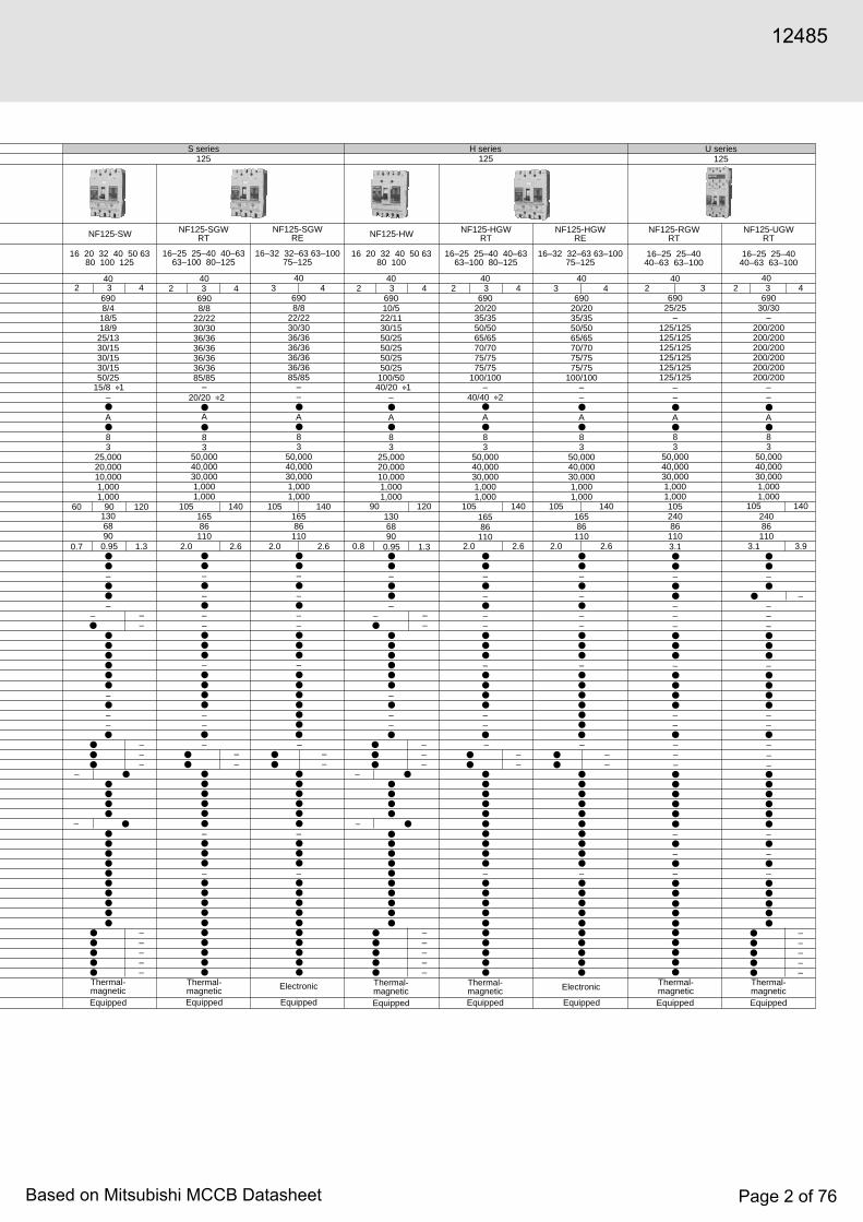
C series S series H series U series
3 4 3 4
NF250-SW
125 150 175200 225 250
40
690––
15/825/1330/1530/1530/1550/25
–
A
62
12,0004,0004,000
–-–
1656892
–
–––
–
–
––
Thermal-magneticEquipped
105 140
2.0 2.6
105 140
2.0 2.6
250
NF250-SGWRT
125–160 160–250
40
6908/8
22/2230/3036/3636/3636/3636/3685/85
–
A
83
25,00015,00010,0001,0001,000
16586110
–
–
––
–
––
●
–
Thermal-magneticEquipped
NF250-SGWRE
125–250
40
6908/8
22/2230/3036/3636/3636/3636/3685/85
––
A
83
25,00015,00010,0001,0001,000
16586110
–
–
––
–
●
–
Electronic
Equipped
NF250-HW
125 150 175200 225 250
40
6905/3–
30/850/1350/1350/1350/13
100/25
–
A
62
12,0004,0004,0001,0001,000
1656892
–
–––
–
–
––
Thermal-magneticEquipped
NF250-HGWRT
125–160 160–250
40
69020/2035/3550/5065/6570/7075/7575/75
100/100–
A
83
25,00015,00010,0001,0001,000
16586
110
–
–
––
–
––
–
–
Thermal-magneticEquipped
250
NF250-HGWRE
125–250
40
–
69020/2035/3550/5065/6570/7075/7575/75
100/100
–
A
83
25,00015,00010,0001,0001,000
16586
110
–
–
––
–
–
–
Electronic
Equipped
105
3.1
2 3
250
NF250-RGWRT
125–160 160–225
40
69025/25
125/125125/125125/125125/125125/125125/125125/125
–
A
83
25,00015,00010,0001,0001,000
24086
110
–
–––
–
––
–
–
–
●Thermal-magnetic
Thermal-magnetic
Equipped
NF250-UGWRT
125–160 160–225
40
69030/30
–200/200200/200200/200200/200200/200200/200
–
A
83
25,00015,00010,0001,0001,000
24086
110
–
–––
–
––
–
–
–
Equipped
2 3 42 3 4
1.3 1.5 1.9
15/8 ✽ 120/20 ✽ 2 40/40 ✽ 2
40/20 ✽ 1–
105 140 105 140
2.0 2.6
105 140 105 140
2.0 2.6
105 140
3.1 3.9
–––
–––
–––
–––
–––
–––
–
–––
–––
–––
–
–
–––––
–––––
432
1.91.51.3
432 432
–
●
●
●●
●●
●●●●
●
●
●●●●●
●●●●●●●●●●
●
●
●
●●
●
●
●●●
●●●●
●●●●●
●●●
●●●●●
●
●
●●
●
●
●●●
●●●●●●
●●●●●
●●●
●●●●●
●●●
●● ●
●
●●
●●●
●●●●●
●●●●●
● ●
● ● –
●
●
●●
●●
●●●●
●
●
●●●●
●●●●●●●●●●
●
●
●●
●
●
●●●
●●●●
●●
●●●
●
●●●
●
●●
●●
●
●
●●
●
●
●●●
●●●●●●
●●●●●●
●●●
●●●●●
●
●
●●
●●
●●●
●●●●
●●●●●
●
●
●●●●●●●●●
●
●
●●
●
●●●
●●●●
●●●●●
● ●
●
●
●●●●●
●●●
●●●
●
●●●●●
●●●●●
●●●●●
●●●●●
●
●
● ● ● ●
–
250
NF250-CW
125 150 175 200225 250
402 3
10/5 ✽ 1
105
600––
10/515/818/918/918/9
35/18
–
A
62
8,0004,0004,000
––
1656892
–
–––
–
–
––
Thermal-magneticEquipped
1.3 1.5
●
●
●●
●●
●●●●
●
●
●●●●●●●●
●●
●
●●●●●
●●●●●●●
●
–
12485
Based on Mitsubishi MCCB Datasheet Page 4 of 76

SeriesFrame Size
Photo
Type name
Rated current In (Amp.)
Rated ambient temperature (°C)Number of polesRated insulation voltage Ui (V)
Ratedshort-circuitbreakingcapacities (kA)
IEC60947-2(Icu/Ics)
AC(50/60Hz)
690V500V440V415V400V380V
DC230V250V
Utilization category
Reverse connection (terminals unmarked)Rated impulse withstand voltage Uimp (kV)Pollution degree
Overall dimensions (mm)
abcca
Installationandconnections
FixedFront
Screw terminal
Synchronous Closing (UVT-S)Non-Synchronous Closing (UVT-N)
Solderless (box) terminal (SL)
Rear (B)Busbar terminal
Plug-inRear (PM)Rear/front IP20 (PM-IP)
Cassette-typeaccessories(option)
Alarm switch (AL)Auxiliary switch (AX)Shunt trip (SHT)
Undervoltage trip (UVT)
Accessorie’s connection(option)
with Lead-wire terminal block (SLT)with Internal terminal type (INT)with Flying leads
Built-inaccessories(option)
Pre-alarm (contact output) ✽ 3 (PAL)Overcurrent trip alarm ✽ 3 (OAL)
(TI)
EnclosureDustproof
(S) ( I )
Handle lock (HL)
(HL-S)Externalaccessories(option)
Marine approval
Mechanical interlock
Handle lock device
(MI)
Lock cover (LC)
Waterproof (W)
Externaloperatinghandle
Door mounting (V)(S)
Mounted on breaker(R)
Electrical operation device
Motor-operated type (MD)
Spring-charge type (MDS)
(F)Insulatingbarrier
Between phase (BA-F)To ground (BA-G)
Terminalcover
Large (TC-L)Small (TC-S)
for rear connection (BTC)for plug-in (PTC)
L/RG/LBV
DNVABS
Automatic tripping device
Trip button
Notes ✽ 1: In case of solderless terminal, interrupting capacity reduces: ( / ).✽ 2: Solid state relay output is option . Please specify if other output is
necessary. (Standard type is thus SLT equipped.)✽ 3: Both PAL and OAL is not available. Only one specified.✽ 4: Specify if for DC use.
C series S series
a cac
b
Suitability for isolation
Mass of front-face type (kg)
Transparent (TTC)
Trip indicator
400
2 3
Rated short-time withstand current Icw (kA)
NF400-CP
H series400
250 300 350 400
40
600–
15/8
36/1836/1825/13
40/2050/25
20/10 ✽ 4 –
A–
83
140257103134
–
–
–
––––
–
–
–
Thermal-magneticEquipped
A–
83
140257103155
–
–
–
––––
–
–
Thermal-magneticEquipped
NF400-SP
250 300 350 400
40
40/40 ✽ 4 –
69010/10(5/5) ✽ 1
30/30(25/25) ✽ 142/42(36/36) ✽ 145/45(36/36) ✽ 145/45(36/36) ✽ 150/50(42/42) ✽ 185/85(65/65) ✽ 1
400
NF400-SEP
200~400adjustable
3 4
–
B5
NF400-HEP
400
2 3 4
185
––
–
4.9 5.7 7.5
––––––
83
140257103155
–
–
–
● ✽ 2–●–
–
–
Electronic
Equipped
40
69010/10(5/5) ✽ 1
30/30(25/25) ✽ 142/42(36/36) ✽ 145/45(36/36) ✽ 145/45(36/36) ✽ 150/50(42/42) ✽ 185/85(65/65) ✽ 1
185
6 7.8
––
–
200~400adjustable
3 4
–
B5
83
140257103155
––
–
–
● ✽ 2–●–
–
––
Electronic
Equipped
–––––
–––––
40
69010/1050/5065/6570/7070/7070/70
100/100
185
6 7.8
––
––
NF400-REP
200~400adjustable
3
–
B5
83
140257103155
––
–
–
● ✽ 2–●–
–
––
–
Electronic
Equipped
40
69015/1070/35125/63125/63125/63125/63150/75
6
––
●
●
●●●●
●●●●●●
●
●
●
●
●
●●●
●
●●●●●●
●●●●●●
●
●
●
●
●●●●
●●●●●●
●
●
●
●●●
●
●●●●●●
●●●
●●
●●●●
●
●
●
●●●●
●●●●●●
●
●
●
●●●
●
●●●●●●
●●●
●●
●
●
●
●●●
●●●●●●
●
●
●
●●●
●
●●●●●
●
●●●●●
●●●–●
●●
●
●
●●●
●●●●●●
●
●
●
●●●
●
●●●●●
●●●
●
●
●–
4.7 5.5
Detailed SpecificationsMolded-Case Circuit Breakers
12485
Based on Mitsubishi MCCB Datasheet Page 5 of 76
2
–
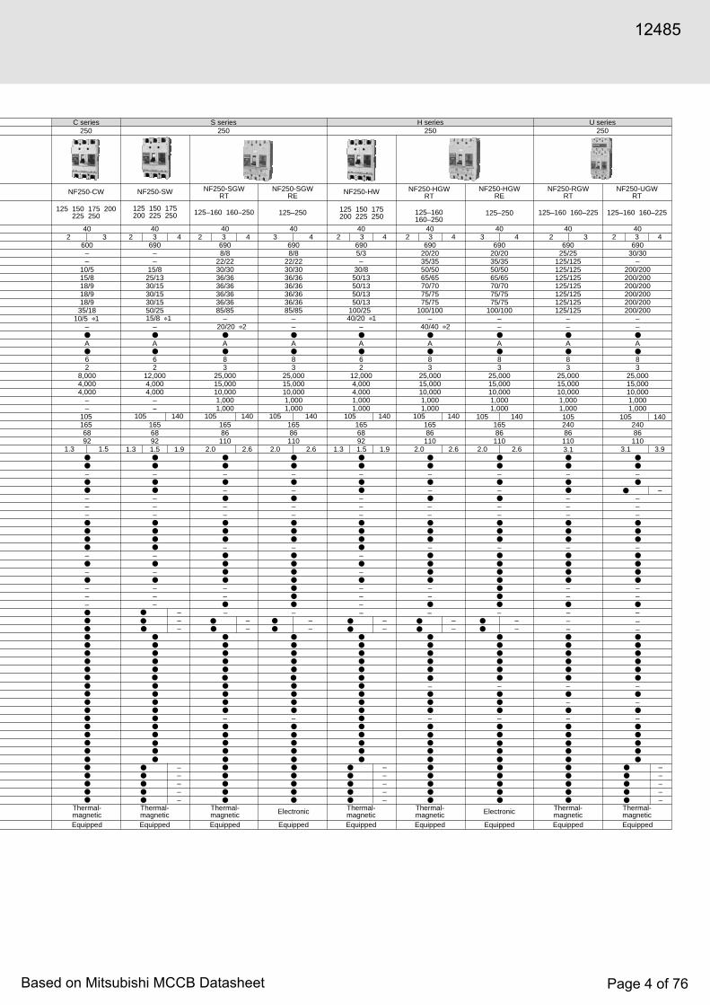
C series S series630
NF630-CP
500 600 630
40
600–
18/936/1836/1836/1840/2050/25
A
83
275103
275103
275103
155
–
–
–
––––
–
–
–
Thermal-magneticEquipped
630H series
630
3 4
210
432
U series400
3 4
140 280297 322
NF400-UEP
200–400adjustable
–
B5
●
83
200252
––
–
–
● ✽ 2–●–
––
–
●–
–
Electronic
Equipped
–
40
69035/35
170/170200/200200/200200/200200/200200/200
––
–
16.7 26.1
210 280322
–
B7.6
83
200252
––
–
–
● ✽ 2–●–
––
–
●–
Electronic
Equipped
–
35/35170/170200/200200/200200/200200/200200/200
––
–
25.7 31.9
2 3
20/10 ✽ 4 –
8.0 9.4
NF630-SP
500 600 630
40
69010/1030/3042/4245/4545/4550/5085/85
A
155
–
–
–
––––
–
–
–
Thermal-magneticEquipped
40/40 ✽ 4 –
210 280
12.59.68.5
––
––––––
NF630-SEP
300~630adjustable
40
69010/1030/3042/4245/4545/4550/5085/85
B– – 7.6
155
–
–
–
● ✽ 2–●–
–
–
–
Electronic
Equipped
–
210 280
10.5 13.6
––
–––––
83
83
275103
3 4
NF630-HEP
300~630adjustable
40
69015/1550/5065/6570/7070/7070/70
100/100
B7.6
155
––
–
–
● ✽ 2–●–––
–
–
–
Electronic
Equipped
–
210 280
10.5 13.6
––––––
83
630U series
3 4
NF630-UEP
300~630adjustable
40
690
630
275103
NF630-REP
300~630adjustable
403
69020/1570/35125/63125/63125/63125/63150/75
B7.6
15510.5
––
–
–
● ✽ 2–●–––
–
–
–
Electronic
Equipped
–
–
83
210
––––––
–
●
●
●
●●●
●
●
●
●●●●
●●●●●●
●
●●●
●
●●●●
●●
●●
●
●●
●●●●●●
●
●
●
●●●
●
●●●
●●●
●–
–––
–
●
●
●
●●
●●●●●●
●
●
●
●●●
●
●●●
●
●
●
●
●
●
●
●●●●
●●●●●●
●
●●●
●
●●●●
●●
●
●●
●●●
●
●
●
●
●
●
●●●●
●●●●●●
●
●●●
●
●●●●
●●
●
●●
●●●●●
●
●
●
●
●
●●●
●●●●●●
●
●●●
●
●●●●
●●
●
●●●
●
●
●
●
●
●
●●●
●●●●●●
●
●●●
●
●●●●
●●
●
●●●
●
●●●
●
● ● –
12485
Based on Mitsubishi MCCB Datasheet Page 6 of 76

SeriesFrame Size
Photo
Type name
Rated current In (Amp.)
Rated ambient temperature (°C)Number of polesRated insulation voltage Ui (V)
Ratedshort-circuitbreakingcapacities (kA)
IEC60947-2(Icu/Ics)
AC(50/60Hz)
690V500V440V415V400V380V
DC230V250V
Utilization category
Reverse connection (terminals unmarked)Rated impulse withstand voltage Uimp (kV)Pollution degree
Overall dimensions (mm)abcca
Installationandconnections
Fixed FrontScrew terminal
Synchronous Closing (UVT-S)Non-Synchronous Closing (UVT-N)
Rear (B)Busbar terminal
Plug-in Rear (PM)Rear/front IP20 (PM-IP)
Cassette-typeaccessories(option) ✽ 5
Alarm switch (AL)Auxiliary switch (AX)Shunt trip (SHT)Undervoltage trip (UVT)
Accessorie’s connection(option)
with Lead-wire terminal block (SLT)with Internal terminal type (INT)with Flying leads
Built-inaccessories(option)
Pre-alarm (contact output) ✽ 3 (PAL)Overcurrent trip alarm ✽ 3 (OAL)
(TI)
EnclosureDustproof (S) ( I )
Handle lock (HL) (HL-S)
Externalaccessories(option)
Marine approval
Mechanical interlock
Handle lock device
(MI)
Lock cover (LC)
Waterproof (W)
Externaloperatinghandle
Door mounting (V)(S)
Mounted on breaker (R)
Electrical operation device
Motor-operated type (MD)
Spring-charge type (MDS)
(F)Insulatingbarrier
Between phase (BA-F)To ground (BA-G)
Terminalcover
Large (TC-L)Small (TC-S)
for rear connection (BTC)for plug-in (PTC)
L/RG/LBV
DNVABS
Automatic tripping device
Trip button
Notes ✽ 1: In case of solderless terminal, interrupting capacity reduces: ( / ).✽ 2: Solid state relay output is option . Please specify if other output is
necessary. (Standard type is thus SLT equipped.)✽ 3: Both PAL and OAL is not available. Only one specified.✽ 4: Specify if for DC use.✽ 5: Cassette-type accessories are not suitable for NF1000-SS, NF1000-SSD,
NF1250-SS, NF1250-SSD, NF1250-UR, NF1600-SS, and NF1600-SSD.
a cac
b
Suitability for isolation
Mass of front-face type (kg)
Transparent (TTC)
Trip indicator
Rated short-time withstand current low (kA)
C series800
NF800-CEP
400~800adjustable
403
600–
18/936/1836/1836/1840/2050/25
B
83
27510315510.9
–
–
–
● ✽ 2–
–
–
–
–
Electronic
Equipped
210
–
9.6
S series800
H series800
NF800-SDP
(700) 800
402––––––––
A
83
2751031559–
–
–
––––
–
–
–
Thermal-magneticEquipped
210
40/40 ✽ 4
–
NF800-SEP
400~800adjustable
403 4
69010/1030/3042/4245/4545/4550/5085/85
B
83
275103155
–
–
–
● ✽ 2–
–
–
–
–
Electronic
Equipped
–
9.6
210 280322
–
B9.6
83
200252
––
–
–
● ✽ 2–●–
––
–
––
Electronic
Equipped
–
35/35170/170200/200200/200200/200200/200200/200
––
––––––
27.6 33.7
– –
800U series
3 4
NF800-UEP
400~800adjustable
40
690
210 280
10.9 14.2
––
–––––
NF800-HEP
400~800adjustable
403 4
69015/1550/5065/6570/7070/7070/70
100/100
B
83
275103155
––
–
–
● ✽ 2–
–––
–
–
–
Electronic
Equipped
–
9.6
210 280
10.9 14.2
–––
– ––
NF800-REP
400~800adjustable
403
69020/1570/35125/63125/63125/63125/63150/75
B
83
21027510315510.9
––
–
–
● ✽ 2–
–––
–
–
–
Electronic
Equipped
–
9.6
–
●
●
●
●●●●●
●
●
●●●●
●●●●●●
●
●
●●●
●
●●●●
●●
●●
●
●
●
●
–––––
●
●
●●●●
●●●●●●
●
●●●
●
●●●●
●●
●●
●
●
●
●
●
●
●●●●
●●●●●●
●
●
●●●
●
●●●●
●●
●
●
●
●●
●●●●●●
●
●
●
●●●
●
●●●
●
●●
●●●●●
●
●
●
●
●
●●●
●●●●●●
●
●
●●●
●
●●●●
●●
●
●●●
●
●
●
●
●
●
●●●
●●●●●●
●
●
●●●
●
●●●●
●●
●
●●●
●
Solderless (box) terminal (SL)
Detailed SpecificationsMolded-Case Circuit Breakers
12485
Based on Mitsubishi MCCB Datasheet Page 7 of 76

2
210 280406
–
B20
–
83
140190
––
–
–
––––
–
––
–
–
Electronic
Equipped
–
25/1365/3385/43
–85/43
–125/63
––
23.5 30.7
1000S series
3 4
NF1000-SS
40
690
–––––
––
– –– –
–
500–600–700–800–900–1000 adjustable
406
40/20 ✽ 4
A–
–
83
210
14019022––
––
–
––––
–
––
–
–
Thermal-magneticEquipped
–
–––––––
––
NF1000-SSD
402–
1000
––
––
210 280406
–
B20
–
83
140190
––
–
–
––––
–
––
–
–
Electronic
Equipped
–
25/1365/3385/43
–85/43
–125/63
––
23.5 30.7
1250S series
1250U series
1600S series
3 4
NF1250-SS
40
690
–––––
600–700–800–1000–1200–1250 adjustable
240 310406
–
B20
–
83
144194
––
–
●(LT)–
––––––
–
––
–
–
–
Electronic
Equipped
–
–85/42125/65
–125/65
–170/85
––––––
–
37.2 46.7
3 4
NF1250-UR
40
690
600–700–800–1000–1200–1250 adjustable
406
40/20 ✽ 4
A–
–
83
210
14019022––
––
–
––––
–
––
–
–
Thermal-magneticEquipped
–
–––––––
––
NF1250-SSD
402–
1250
–
––
– –– –
–
210 280406
–
B20
–
83
140190
––
––
–
––––––
–
––
–
–
Electronic
Equipped
–
25/1365/3385/43
–85/43
–125/63
––––––
–
34.5 41.2
3 4
NF1600-SS
40
690
–––––
800–1000–1200–1400–1500–1600 adjustable
406
40/20 ✽ 4
A–
–
83
210
14019032––
––
–
––––––
–
––
–
●
●●●
●●●●●●
●
●
●
●●
●
●●●●
●●
●
●
●●
●●●●●●
●
●
●
●●
●
●●●●
●●
●●
●●
●
●●●
●●●●●●
●
●
●
●●
●
●●●●
●
●●
●●●●●
●
●
●
●●
●
●
●●
●
●●
●●●●●●
●
●●
●
●
●●
●
●●●●
●
●●
●
●
●●
●●●●●●
●
●
●
●●
●
●●●–
●
●●
●●●●●●
●
●
●
●●
●
●●●––
magnetic
Equipped
–
–––––––
––
NF1600-SSD
402–
1600
12485
Based on Mitsubishi MCCB Datasheet Page 8 of 76
2-pole
3-pole
ALLeft-sidemounting
Right-sidemounting
Operating handleAX Lead wire
direction
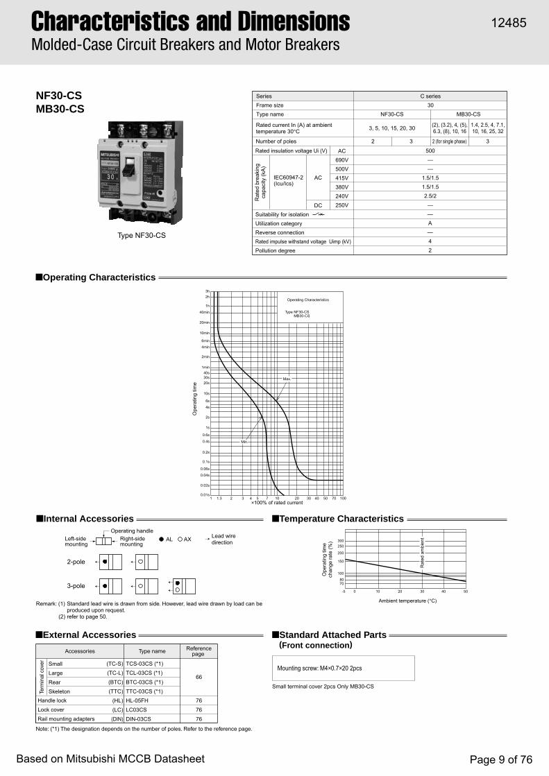
NF30-CSMB30-CS
Type NF30-CS
■ Operating Characteristics
■ Internal Accessories
■ External Accessories ■ Standard Attached Parts(Front connection)
■ Temperature Characteristics
Note: (*1) The designation depends on the number of poles. Refer to the reference page.
Remark: (1) Standard lead wire is drawn from side. However, lead wire drawn by load can beproduced upon request.
(2) refer to page 50.
Mounting screw: M4×0.7×20 2pcs
Rat
ed b
reak
ing
capa
city
(kA
)
Rated current In (A) at ambienttemperature 30°C
Number of poles 32
IEC60947-2(Icu/Ics)
AC
DC
Rated insulation voltage Ui (V)
Suitability for isolationUtilization categoryReverse connection Rated impulse withstand voltage Uimp (kV)Pollution degree
500——
1.5/1.51.5/1.52.5/2
——A—42
Type name NF30-CSFrame size 30Series C series
3, 5, 10, 15, 20, 30
AC690V500V415V380V240V250V
32 (for single phase)
MB30-CS
(2), (3.2), 4, (5),6.3, (8), 10, 16
1.4, 2.5, 4, 7.1,10, 16, 25, 32
Type NF30-CSMB30-CS
Operating Characteristics
Max.
Min.
1 1.30.01s
0.02s
0.04s
0.1s
0.2s
0.4s
0.6s
1s
2s
4s
6s
10s
20s30s40s
1min
2min
4min
6min
10min
20min
40min
1h
2h3h
0.06s
2 3 4 5 7 10 20 30 40 50 70 100
Ope
ratin
g tim
e
×100% of rated current
Ambient temperature (°C)
Ope
ratin
g tim
ech
ange
rate
(%)
Rat
ed a
mbi
ent
7080
-5 0 10 20 30 40 50
100
150
200
250300
Small terminal cover 2pcs Only MB30-CS
66
76
76
76
Term
inal
cov
er Small
Large
Rear
Skeleton
TCS-03CS (*1)
TCL-03CS (*1)
BTC-03CS (*1)
TTC-03CS (*1)
HL-05FH
LC03CS
DIN-03CS
(TC-S)
(TC-L)
(BTC)
(TTC)
(HL)
(LC)(DIN)
Handle lock
Lock cover
Rail mounting adapters
Accessories Type name Referencepage
Characteristics and DimensionsMolded-Case Circuit Breakers and Motor Breakers
12485
Based on Mitsubishi MCCB Datasheet Page 9 of 76

6
Front connection
Rear connection
Lead-wire Terminal block (LT)
IEC Rail Mounting Adapter
4723.5
67.545
64 54
ø8.5
10
14.5
12.5 (max.)
76.5
96
Mtg. hole M5 screw
Bus t max. =3
Bus drilling fordirect connection
2-pole 3-pole
2-pole 3-poleDrilling plan
ø5
28
49
523
67
6
ø5.5
84
23.5
BreakerM4 × 0.7 taps or ø5
2-pole 3-pole
2-pole 3-pole Drilling plan
8476.5
23.5
Breaker
ø14
M4 × 0.7 tapsor ø5
76.5
Mtg plat t max. =3.2
Insulating tube
5
38.5
58.5
8
45 (m
in)
25 (m
in)
Breaker mtgM4 × 0.7 screwM6 screw
47
23.5
Front-plate cutout
1mm clearance oneach side of handle
Breaker
R2
3-pole
2-pole
2018
20
55
35 100
431
52
55
58
70
35mm IEC-rail adapterfor installation
Installation utensilfor 35mm IEC-rail
2-pole 3-pole
5
63
7.5
225
.5
8
18.5
9.5
80.5
40.5
2
22
Terminal cover (optional)M3.5 self-lifting terminal
77.5
9.5
12485
Based on Mitsubishi MCCB Datasheet Page 10 of 76
Characteristics and DimensionsMolded-Case Circuit Breakers and Motor Breakers
2-pole
3-pole
AL
Left-sidemounting
Right-sidemounting
Breaker handle
AX
SHT or UVT
Lead wiredirection
Type nameType name
F05SW (*1)F 61
63
60
Ml Ml-05SW3 (*1) 75S S05SW
V V05SWF
R
Small TC-S TCS-05SW3W (*1)
66
76
Large TC-L TCL-05SW3W (*1)
Skeleton TTC TTC-05SW3 (*1)
Rear BTC BTC-05SW3W (*1)
LC LC-05SW
Plug-in PTC PTC-05SW3W (*1)(*2)HL HLN-05SW
HLF-05SW
DIN-05SW 76
HL-S HLS-05SW (*1)
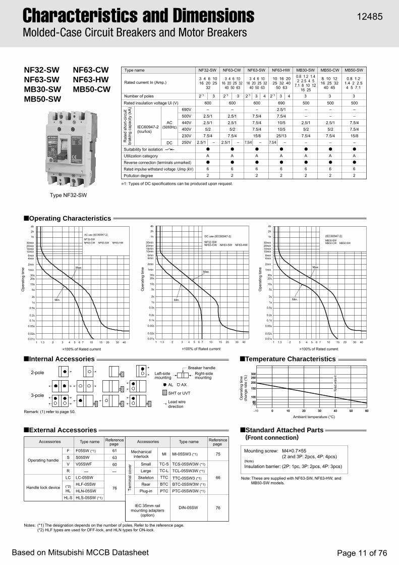
NF32-SWNF63-SWMB30-SWMB50-SW
■ Operating Characteristics
■ Internal Accessories
■ External Accessories ■ Standard Attached Parts(Front connection)
■ Temperature Characteristics
Notes: (*1) The designation depends on the number of poles. Refer to the reference page.(*2) HLF types are used for OFF-lock, and HLN types for ON-lock.
Remark: (1) refer to page 50.
Note: These are supplied with NF63-SW, NF63-HW, and MB50-SW models.
Mounting screw: M4×0.7×55 (2 and 3P: 2pcs, 4P: 4pcs)
(Note)
Insulation barrier: (2P: 1pc, 3P: 2pcs, 4P: 3pcs)
NF63-CWNF63-HWMB50-CW
Min.
Max.
×100% of Rated current
Ope
ratin
g tim
e
NF63-CW NF63-SW NF63-HWNF32-SW
AC use (IEC60947-2)
4h
2h
1h
30min 20min 14min 10min
6min 4min
2min
1min
30s20s
10s
5s
2s
1s
0.5s
0.2s
0.1s
0.05s
0.02s
1 1.3 2 3 4 5 6 7 10 15 20 30 400.01s
NF63-CW NF63-SW NF63-HWNF32-SW
DC use (IEC60947-2)
Min.
Max.
×100% of Rated current
Ope
ratin
g tim
e
4h
2h
1h
30min 20min 14min 10min
6min 4min
2min
1min
30s20s
10s
5s
2s
1s
0.5s
0.2s
0.1s
0.05s
0.02s
1 1.3 2 3 4 5 6 7 10 15 20 30 400.01s
Min.
Max.
(IEC60947-2)
MB50-CW MB50-SWMB30-SW
×100% of Rated current
Ope
ratin
g tim
e
4h
2h
1h
30min 20min 14min 10min
6min 4min
2min
1min
30s20s
10s
5s
2s
1s
0.5s
0.2s
0.1s
0.05s
0.02s
1 1.3 2 3 4 5 6 7 10 15 20 30 400.01s
Rated
ambie
nt
Ambient temperature (°C)
Ope
ratin
g tim
ech
ange
rate
(%) 300
250
200
150
100
8070
6050403020100
300250
200
150
100
8070
6050403020100–10
Term
inal
cov
erR
ated
sho
rt-ci
rcui
tbr
akin
g ca
paci
ty (k
A)
Rated current In (Amp.)
Number of poles 32∗1
–2.5/1
IEC60947-2(Icu/Ics)
AC(50/60Hz)
DC
Rated insulation voltage Ui (V)
Suitability for isolationUtilization categoryReverse connection (terminals unmarked)Rated impulse withstand voltage Uimp (kV)Pollution degree
600–
2.5/12.5/15/2
7.5/4
●
A●
62
Type name NF32-SW
3 4 6 1016 20 25
32
690V500V440V400V230V250V
32∗1
– –2.5/1
600–
2.5/12.5/15/2
7.5/4
●
A●
62
NF63-CW
3 4 6 1016 20 25 32
40 50 63
2∗1 3 4
7.5/4
600–
7.5/47.5/47.5/415/8
●
A●
62
NF63-SW
3 4 6 1016 20 25 32
40 50 63
–
2∗1 3 4
7.5/4
6902.5/17.5/410/510/525/13
●
A●
62
NF63-HW
10 16 2025 32 40
50 63
8 10 1216 25 32
40 45
3
500––
2.5/15/2
7.5/4–●
A●
62
MB30-SW0.8 1.2 1.42 2.5 4 5
7.1 8 10 12 16 25
3
500––
2.5/15/2
7.5/4–●
A●
62
MB50-CW
0.8 1.21.4 2 2.54 5 7.1
3
500––
7.5/47.5/415/8
–●
A●
62
MB50-SW
Accessories Accessories
Mechanicalinterlock
IEC 35mm railmounting adapters
(option)
Referencepage
Referencepage
Operating handle
Handle lock device
— —
✽ 1: Types of DC specifications can be produced upon request.
Type NF32-SW
12485
Based on Mitsubishi MCCB Datasheet Page 11 of 76

6
Front connection
Rear connection
Plug-in
Drilling plan4-pole3-pole2-pole
M4×0.7 tapsor 5mm dia.hole
Breaker
4-pole3-pole2-pole
Conductor drillingfor direct connection
(Conductor thickness t=5 max.)
φ5.5(6.5mm-diameter for 63A)
Screw terminal
Applicablewire size:1.6mm-dia.to 22mm2
M5×0.8 screw(M6 for 63A)
Neutral pole
Trip button
Insulation barrier(removable)
Mounting hole
50
22
25
50
50
75
25
75
100
5013
0
111
84
24
45
φ8.5
61
68
724
90
12.5 max.
6
2525
111
φ4.5
2-pole
min.
M4×0.7 tapsor 5mm-dia.hole
Breaker
Drilling plan
4-pole3-pole
M4×0.7 screwfor mounting breaker
M6 screw
Insulation tube
Mounting panelt=3.2max
φ14
111
25
25
75
25
5025
50
6
4268
72
8
27
111
Front-panel cutout
1.0mm clearance on each side ofthe handle frame.
Breaker
4-pole
3-pole
2-pole
50
22.5
70
52R1
φ6.5
Details of terminal
M6 screw
M5×0.8terminal block mounting screw
Plug-in terminal block
Mounting panel
Center line ofbreaker body
Conductor drillingfor direct connection2-pole
4-pole3-pole
Cutout and drilling plan
4-pole3-pole2-pole6mm-dia.hole oror M5×0.8 taps
Breaker (plug-in terminal block)
11
54
5454
80
57 82
25
107
50
50
80
75
25
105
111
55
25
16.5 max.
7
3
180
83.5
85
30
21
89
5.5 15.5
10
12485
Based on Mitsubishi MCCB Datasheet Page 12 of 76

NF125-CWNF125-HW
NF125-SWMB100-SW
Remark: (1) Only AC characteristics are available for the model MB100-SW.
∗1: When wired as shown at the bottom of page 13, 3-pole models can be used for up to 400 V DC, and 4-pole models for up to 500 V DC.
F F1SW (*1) 61
6360
Ml Ml-05SW3 (*1) 75S S1SWV V1SW (*2)
R R1SWSmall TC-S TCS-1SW3W (*1)
6664 Large TC-L TCL-1SW3W (*1)
Skeleton TTC TTC-1SW3 (*1)
Rear BTC BTC-1SW3W (*1)LC LC-1SW
76 Pulg-in PTC PTC-1SW3W (*1)(*4)HL
HLF-1SW
DIN-1SW3 (*1) 76
67
HLN-1SWHL-S HLS-1SW (*1)(*4)
MDS-NF1SWE (*3)
2-pole
3, 4-poleAL AX
■ Operating Characteristics
■ Internal Accessories ■ Ambient Compensating Curve
■ External Accessories ■ Standard Attached Parts(Front connection)
Rat
ed s
hort-
circ
uit
brak
ing
capa
city
(kA
)
Rated current In (Amp.)
Number of poles 32 2 3 342 3 4
IEC60947-2(Icu/Ics)
AC(50/60Hz)
DC ∗1
Rated insulation voltage Ui (V)
Suitability for isolationUtilization categoryReverse connection (terminals unmarked)Rated impulse withstand voltage Uimp (kV)Pollution degree
600–
7.5/410/510/530/15
7.5/4–
–7.5/4
15/8–
40/2015/8 40/20
40/20–
15/8
– –
–––●
A●
83
●
A●
83
●
A●
83
●
A●
83
6908/418/925/1330/1550/25
69010/530/1550/2550/25100/50
500––
25/1330/1550/25
–––
Type name NF125-CW NF125-SW NF125-HW MB100-SW(12.5) (16)
(25) 32 (40)45 63 7190 100
50 63 80100 125
16 20 32 4050 63 80
100
16 20 32 4050 63 80100 125
690V500V440V400V230V250V400V500V
Left-sidemounting
Right-sidemounting
Operating handle
SHT or UVTLead wiredirection
Mounting screw: M4×0.7×55 (2 and 3P: 2pcs, 4P: 4pcs)
(Note)
Insulation barrier: (2P: 1pc, 3P: 2pcs, 4P: 3pcs)
Type name Type name
Term
inal
cov
er
(IEC 60947-2)MB100-SW 40A~100ANF125-HW 40A~100ANF125-SW 40A~100ANF125-CW 50A~100A
(40A~50A)
(60A~100A)Max.
Max.
breaking time
Max. total
AC
DC
Instantaneous tripTime-delay trip
Min.
×100% of Rated current
Ope
ratin
g tim
e
4h
2h
1h
30min 20min 14min 10min 6min 4min
2min
1min
30s20s
10s
5s
2s
1s
0.5s
0.2s
0.1s
0.05s
0.02s
1 1.3 2 3 4 5 6 7 10 15 20 30 40 500.01s
Min.
(IEC 60947-2)NF125-SW 125ANF125-CW 125A
Max.
breaking timeMax. total
AC
DC
Instantaneous tripTime-delay trip
×100% of Rated current ×100% of Rated current
Ope
ratin
g tim
e
4h
2h
1h
30min 20min 14min 10min 6min 4min
2min
1min
30s20s
10s
5s
2s
1s
0.5s
0.2s
0.1s
0.05s
0.02s
1 1.3 2 3 4 5 6 7 10 15 20 30 40 50 1 1.3 2 3 4 5 6 7 10 15 20 30 40 500.01s
Ope
ratin
g tim
e
4h
2h
1h
30min 20min 14min 10min 6min 4min
2min
1min
30s20s
10s
5s
2s
1s
0.5s
0.2s
0.1s
0.05s
0.02s
0.01s
×100% of Rated current
Ope
ratin
g tim
e
4h
2h
1h
30min 20min 14min 10min 6min 4min
2min
1min
30s20s
10s
5s
2s
1s
0.5s
0.2s
0.1s
0.05s
0.02s
1 1.3 2 3 4 5 6 7 10 15 20 30 40 50 60 700.01s
130
120
110
100
90
800 10 20 30 40 50 60
Ambient temperature (°C)
Rate
d am
bien
t
–10
Cur
rent
ratin
g (%
)
Accessories AccessoriesReferencepage
Referencepage
Operating handle
Handle lock device
Mechanicalinterlock
IEC 35mm railmounting adapters
Electricaloperation device
Notes: (*1) The designation depends on the number of poles. Refer to the reference page.(*2) Attach the letter "F" to the end of designation for a fixed type.(*3) Specify the working voltage. An order should be placed at the same time as an order of circuit breaker main body.(*4) HLF and HLS types are used for OFF-lock, and HLN types for ON-lock.
Remark: (1) refer to page 50.
Note: These are supplied with NF125-SW, NF125-HW, and MB100-SW models.
AC
DC
Min.
breaking time
Max. total
Max.
(IEC 60947-2)NF125-HW 32A
MB100-SW 32ANF125-SW 32A
Time-delay trip Instantaneous trip
DC
AC
Min.
breaking timeMax. total
(IEC 60947-2)MB100-SW 12.5A~25ANF125-HW 16A~20ANF125-SW 16A~20A
Max.
Instantaneous tripTime-delay trip
Type NF125-CW
Characteristics and DimensionsMolded-Case Circuit Breakers and Motor Breakers
12485
Based on Mitsubishi MCCB Datasheet Page 13 of 76

6
Front connection
Rear connection
Plug-in
M5×0.8Terminal blockmounting screw
4-pole
4-pole
2-pole 3-pole2-pole
3-pole
Drilling plan
Plug-in terminal block
Mounting plateBreaker (plug-in terminal block)
6mm-dia. holeor M5×0.8 taps
Details of terminal
M8 screw
Conductor drillingfor direct connection
134
φ8.5
12
16.5 max.
65
30
90
125
60
95
205.5
30
21
11
190
98
67 97
30 60
127
5656
9454
30
12.5
LCLCCL
LC
89
LC
R1 R1
2-pole
Breaker
52
86
3-pole
28
4-pole
57
Front-panel cutout
1.0mm clearance on each sideof the handle frame.
CL
CL
LC
LC
Mounting base11
0-11
1
4-pole
30
112
30
90
2-pole
6
3-pole
4-pole
102
52
15
72
68
8.5
2.5
15
54.5
104.5
15
2.5
16
112
60
5
30
60
30
3-pole2-pole
M4×0.7 taps or5mm-dia. hole
Mounting platet=3.2 max.
Stud rotatableby 90°
Connectionallowance
M8 bolt
Insulationtube
M4×0.7breakermounting screw
Breaker
Drilling plan
φ18
CLCL
CL
CL
LC
4-pole
110-
111
30
130
112
4-pole
120
90
30
Neutralpole
50
60
30
90
60
22
24
84 50
68
61
45
724
90
φ8.5
8
19 max.
30
3-pole
3-pole
2-pole
2-pole
Tripbutton
Insulation barrier(removable)
Mounting hole
Conductor drillingfor direct connection
(Conductor thickness t=5 max.)
Breaker
Drilling plan
M4X0.7 tapsor 5mm-dia. hole
M8 screw
Solderless terminalfor wire size
14~2/0AWG CU/AL
Wire connection
LC
LC
LC LCLC
LCLC
CL
Remark: 2-pole model of NF125-HW are 3-pole model with the central pole removed.
12485
Based on Mitsubishi MCCB Datasheet Page 14 of 76
Characteristics and DimensionsMolded-Case Circuit Breakers and Motor Breakers
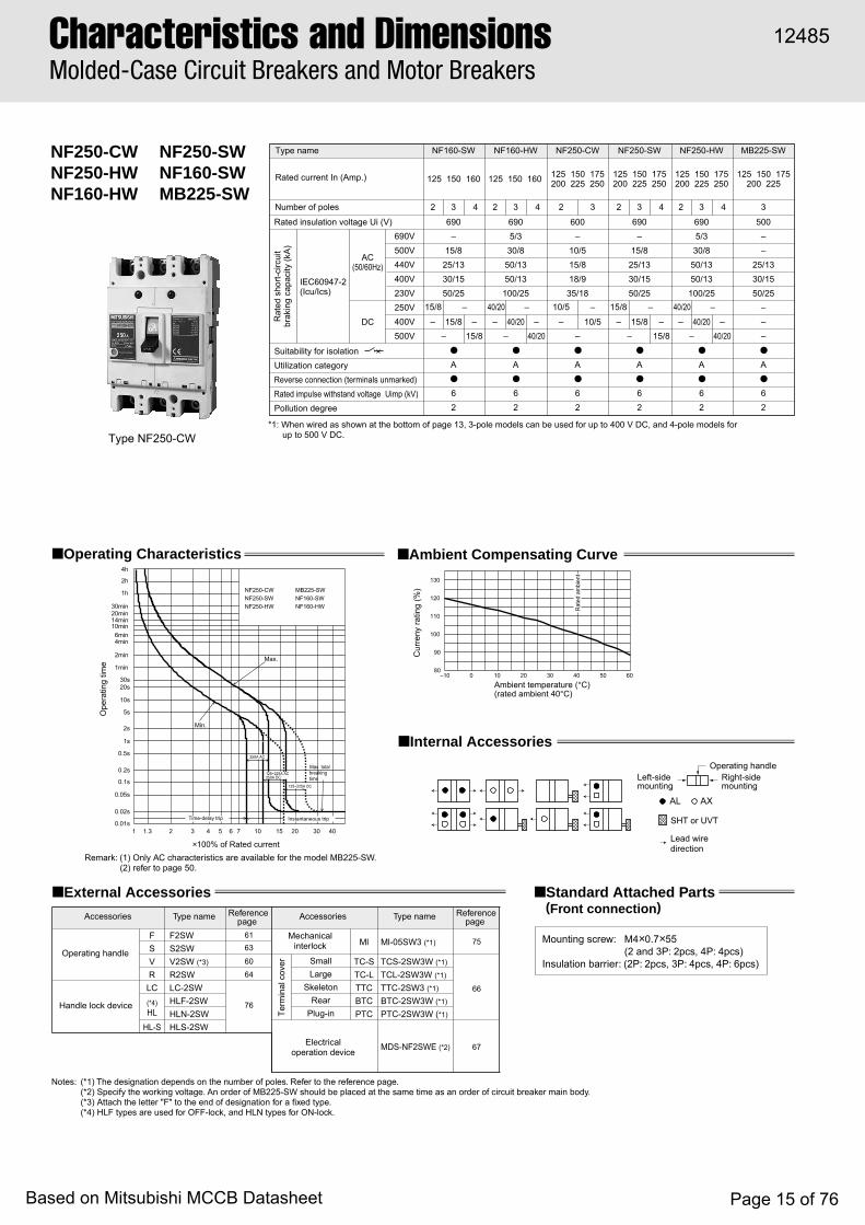
NF250-CWNF250-HWNF160-HW
NF250-SWNF160-SWMB225-SW
■ External Accessories ■ Standard Attached Parts(Front connection)
F F2SW 6163
60
64
Ml Ml-05SW3 (*1) 75S S2SWV V2SW (*3)
R R2SWSmall TC-S TCS-2SW3W (*1)
66
67
Large TC-L TCL-2SW3W (*1)
Skeleton TTC TTC-2SW3 (*1)
Rear BTC BTC-2SW3W (*1)
LC LC-2SW
76Plug-in PTC PTC-2SW3W (*1)
(*4)HL
HLF-2SW
MDS-NF2SWE (*2)
HLN-2SWHL-S HLS-2SW
*1: When wired as shown at the bottom of page 13, 3-pole models can be used for up to 400 V DC, and 4-pole models for up to 500 V DC.
Rat
ed s
hort-
circ
uit
brak
ing
capa
city
(kA
)
Rated current In (Amp.)
Number of poles 2 3 2 3 4
IEC60947-2(Icu/Ics)
AC(50/60Hz)
DC
Rated insulation voltage Ui (V)
Suitability for isolationUtilization categoryReverse connection (terminals unmarked)Rated impulse withstand voltage Uimp (kV)Pollution degree
600–
10/515/818/935/18
–●
A●
62
Type name NF250-CW
125 150 175200 225 250
690–
15/825/1330/1550/25
15/8
●
A●
62
NF250-SW
125 150 175200 225 250
690V500V440V400V230V250V400V500V
10/5 15/8– –
– 10/5 – –15/8–
2 3 4
6905/330/850/1350/13100/25
40/20
●
A●
62
NF250-HW
125 150 175200 225 250
3
500––
25/1330/1550/25
–––●
A●
62
MB225-SW
125 150 175200 225
40/20 –
– –40/20–
2 3 4
6905/330/850/1350/13100/25
40/20
●
A●
62
NF160-HW
40/20 –
– –40/20–
2 3 4
690–
15/825/1330/1550/25
15/8
●
A●
62
NF160-SW
125 150 160 125 150 160
15/8 –
– –15/8–
■ Operating Characteristics
NF160-HWNF160-SWMB225-SW
NF250-HWNF250-SWNF250-CW
time
Max.
Max. total
Instantaneous trip
breaking
Min.
Time-delay trip
×100% of Rated current
Ope
ratin
g tim
e
4h
2h
1h
30min 20min 14min 10min 6min 4min
2min
1min
30s20s
10s
5s
2s
1s
0.5s
0.2s
0.1s
0.05s
0.02s
1 1.3 2 3 4 5 6 7 10 15 20 30 400.01s
Cur
reny
ratin
g (%
)
Rat
ed a
mbi
ent
–10 10 20 30 40 50 6080
90
100
110
120
130
Ambient temperature (°C)(rated ambient 40°C)
0
Term
inal
cov
er
Mounting screw: M4×0.7×55 (2 and 3P: 2pcs, 4P: 4pcs)
Insulation barrier: (2P: 2pcs, 3P: 4pcs, 4P: 6pcs)
AL AX
■ Internal Accessories
Left-sidemounting
Right-sidemounting
Operating handle
SHT or UVT
Lead wiredirection
■ Ambient Compensating Curve
Notes: (*1) The designation depends on the number of poles. Refer to the reference page.(*2) Specify the working voltage. An order of MB225-SW should be placed at the same time as an order of circuit breaker main body.(*3) Attach the letter "F" to the end of designation for a fixed type.(*4) HLF types are used for OFF-lock, and HLN types for ON-lock.
Type nameType nameAccessories Accessories
Mechanicalinterlock
Referencepage
Referencepage
Operating handle
Handle lock device
Electricaloperation device
125~225A DC
125~225A AC250A DC
250A AC
Type NF250-CW
Remark: (1) Only AC characteristics are available for the model MB225-SW.(2) refer to page 50.
12485
Based on Mitsubishi MCCB Datasheet Page 15 of 76

6
Front connection
Rear connection
Plug-in
4-pole3-pole
φ9M8 bolt
Stud attachable in thisderection only
105
142
54 8058
.558
.5
Breaker (Terminal block)
Drilling plan
Con
nect
ion
al
low
ance
Insulating barrier
M6Terminal blockmounting screw
φ7
Plug-in terminal block
22
15
70
107
70
14
6
153
70
20
2834
.514
4
32
18
200
86
Mounting plate
3-pole
4-pole
100
52
32.5
Breaker
1mm clearanceon each sideof handle
Front-plate cutout
R1
Breaker
4-pole3-pole
144
126
35
105
35
70
105
6
8
3-pole
4-pole
Insulatingtube
M4×0.7taps
or φ5
Drilling plan106
71
72
68
ø24
M4×0.7breakermountingscrew
φ9M8 bolt
Connectionallowance
Insulatingtube Stud can be
rotated 90°Mounting plate t max.=3.2
35
70
144
20
22
15
15
30
125200
175A 14 95mm2
250A 70 125mm2
Wire connection
Solderless terminalfor wire size
4-pole3-pole
Neutralpole
4-pole3-pole
144
165
100
100
35
105
140
126
35φ8.5
ø4.5
(Hex-soket)
M4×0.7 tapsor φ5
Drilling plan
Breaker
M8 bolt
(Bus t max.=7)
Bus drilling fordirect connection
Trip button
Mounting hole
Insulating barrier(removable)
35
φ8.5
10
23 max.22
70
24
92
4 72
45
68
61
50102
105
Remarks: 1. 2-pole models are 3-pole models with the central pole removed.2. Only 2- and 3-pole models are available for the model of NF250-CW, and only 3-pole models are available
for the model of MB225-SW.
12485
Based on Mitsubishi MCCB Datasheet Page 16 of 76

AL AX F 61
6360
Ml 75
66
S
V Small TC-S
67
64 Large TC-L
Skeleton TTC
Rear BTC
LC
Plug-in PTC
(*2)
HL76
76HL-S
NF250-SGWNF160-SGWNF125-SGW
NF250-HGWNF160-HGWNF125-HGW
Ml-05SW3 (*1)
TCS-2GSW3W (*1)
TCL-2GSW3W (*1)
TTC-2GSW3 (*1)
BTC-2GSW3W (*1)
PTC-2GSW3W (*1)
MDS-NF2GSWE(*4)
F2GSW
S2GSW
V2GSW (*3)
R R2GSWLC-2GSW
HLN-2GSW
HLF-2GSW
HLS-2GSW
Rat
ed s
hort
-circ
uit
brak
ing
capa
city
(kA
)R
ated
sho
rt-c
ircui
tbr
akin
g ca
paci
ty (k
A)
Rated current In (Amp.)
Number of poles
IEC60947-2(Icu/Ics)
AC(50/60Hz)
DC ∗1
Rated insulation voltage Ui (V)
Suitability for isolationUtilization categoryReverse connection (terminals unmarked)Rated impulse withstand voltage Uimp (kV)Pollution degree
Type name
690V500V440V400V230V300V500V600V
6908/8
30/3036/3636/3685/85
NF160-SGWRT
2 3 4
20/20– 20/20
– 20/20
––
●
A●
83
125–160
6908/8
30/3036/3636/3685/85
NF250-SGWRT
125–160,160–250
2 3 4
20/20– 20/20
– 20/20
––
●
A●
83
69020/2050/5065/6575/75
100/100
NF250-HGWRT
125–160160–250
2 3 4
40/40– 40/40
– 40/40
––
●
A●
83
6908/8
30/3036/3636/3685/85
–––
NF250-SGWRE
125–250
3 4
●
A●
83
69020/2050/5065/6575/75
100/100–––
NF250-HGWRE
125–250
3 4
●
A●
83
6908/8
30/3036/3636/3685/85
–––
NF160-SGWRE
80–160
3 4
●
A●
83
Rated current In (Amp.)
Number of poles
IEC60947-2(Icu/Ics)
AC(50/60Hz)
DC ∗1
Rated insulation voltage Ui (V)
Suitability for isolationUtilization categoryReverse connection (terminals unmarked)Rated impulse withstand voltage Uimp (kV)Pollution degree
69020/2050/5065/6575/75
100/100
Type name NF160-HGWRT
690V500V440V400V230V300V500V600V
2 3 4
40/40– 40/40
– 40/40
––
●
A●
83
69020/2050/5065/6575/75
100/100–––
NF160-HGWRE
80–160125–160
3 4
●
A●
83
6908/8
30/3036/3636/3685/85
NF125-SGWRT
16–25, 25–40,40–63, 63–100,
80–125
16–25, 25–40,40–63, 63–100,
80–125
16–32, 32–63,63–100, 75–125
16–32, 32–63,63–100, 75–125
2 3 4
20/20– 20/20
– 20/20
––
●
A●
83
69020/2050/5065/6575/75
100/100
NF125-HGWRT
2 3 4
40/40– 40/40
– 40/40
––
●
A●
83
6908/8
30/3036/3636/3685/85
–––
NF125-SGWRE
3 4
●
A●
83
69020/2050/5065/6575/75
100/100–––
NF125-HGWRE
3 4
●
A●
83
■ Operating Characteristics
■ Internal Accessories ■ External Accessories
Term
inal
cov
er
Left-sidemounting
Right-sidemounting
Operating handle
SHT or UVT Lead wire direction
×100% of Rated current
Ope
ratin
g tim
e
4h
2h
1h
30min 20min 14min 10min
6min 4min
2min
1min
30s20s
10s
5s
2s
1s
0.5s
0.2s
0.1s
0.05s
0.02s
1 1.3 2 3 4 5 6 7 10 15 20 30 400.01s
×100% of Rated current
Ope
ratin
g tim
e
4h
2h
1h
30min 20min 14min 10min
6min 4min
2min
1min
30s20s
10s
5s
2s
1s
0.5s
0.2s
0.1s
0.05s
0.02s
1 1.3 2 3 4 5 6 7 10 15 20 30 400.01s
×100% of Rated current
Ope
ratin
g tim
e
4h
2h
1h
30min 20min 14min 10min
6min 4min
2min
1min
30s20s
10s
5s
2s
1s
0.5s
0.2s
0.1s
0.05s
0.02s
1 1.3 2 3 4 5 6 7 10 15 20 30 400.01s
130
120
110
100
90
800 10 20 30 40 50 60
(rated ambient 40°C)Ambient temperature (°C)
Mounting screw : M4 × 0.7 × 73 (4pcs)Insulation barrier : (2P : 2pcs, 3P : 4pcs, 4P : 6pcs)
Rat
ed a
mbi
ent
Cur
rent
ratin
g (%
)
–10
RT type RE type
Ambient temperature (°C)10 20 30 40 50 60–10
130
120
110
100
70
80
90
Der
atin
g of
Loa
d cu
rren
t (%
)
0
Rat
ed a
mbi
ent
∗1: Use either 2-pole. When wired as shown at the bottom of page 13, 3-pole models can be used for up to 500 V DC, and 4-pole mo dels for up to 600V DC.
■ Ambient Compensating Curve
Remark: (1) refer to page 50.
Type nameAccessories
Mechanicalinterlock
Referencepage Type nameAccessories Reference
page
Operating handle
Handle lock device
OFF Lock with 3 Padlock HLF3-2GSW Electricaloperation device
Notes:(*1) The designation depends
on the number of poles. Refer to the reference page.
(*2) HLF types are used for OFF-lock, and HLN types for ON-lock.
(*3) Attach the letter “F” to the end of designation for a fixed type.
(*4) Specify the working voltage.
Instantaneous tripcurrent ratio
DC x In (%)
AC x In (%)
1300±2601000±200
IEC 60947-2
AC
DC
16-25A (Rated current In=25A)NF125-SGW/HGW 25-40A (Rated current In=40A)
Min.
breakingMax. total
Max.
time
Thermal-Adjustable types
Time-delay trip Instantaneous trip
AC x In (%)1000±200
Instantaneous tripcurrent ratio
DC x In (%)1300±260
IEC 60947-2
AC
DC
Min.
breakingMax. total
Max.
time
NF125-SGW/HGW 63-100A (Rated current In=100A) 40-63A (Rated current In=63A)
Thermal-Adjustable types
Time-delay trip Instantaneous trip
Instantaneous trip adjustmentrange
Positionof notch
468
10
400±80600800
1000±200
AC x In (%)
520±104
DC x In (%)
78010401300±260
(Adjustable range)
(Adjustable range)DC
AC
IEC 60947-2NF125-SGW/HGW 80-125A (Rated current In=125A)NF160-SGW/HGW 125-160A (Rated current In=160A)NF250-SGW/HGW 160-250A (Rated current In=250A)
time
Max.
Max. totalbreaking
Min.
Thermal-Adjustable types
Time-delay trip Instantaneous trip
■ Standard Attached Parts (Front connection)
Type NF250-SGW
±15%
STD pickup current IS
STD operating time TS
Ir × (2-2.5-3-3.5-4 -5-6-7-8-10)
(at 200%)
LTD operating time TL
0.06±0.02s0.1±0.03s
0.2±0.04s0.3±0.06s
Pre-alarmpickup current IPIr × (0.70-0.75 -0.8-0.85-0.9 -0.95-1.0) ± 10%
12-60-80-100s ± 20%
Pre-alarm operating time TP
TLTP= 2 ± 20%(at 200%)
Max.total breaking time
In × (4~14) ±15%INST pickup current Il
0.01s
0.02s
0.05s
0.1s
0.2s
0.5s
1s
2s
5s
10s
20s
1min
30s
2min
4min6min
10min
20min30min
1h
2h
4h
Ope
ratin
g tim
e
0.6 0.7 4020151065 7 3042 31.31
× 100% of Current setting
Note) Instantaneous tripping current (× 100% of In)
NF125-SGW NF125-HGWNote)Current setting Ir Rated current In16~ 32A32~ 63A63~ 100A75~ 125A
32A63A
100A125A
(Adjustable)
Electric types
(at 200%)
± 20%2
TP = TL
Pre-alarm operating time TP
12-60-80-100s ± 20%
Ir × (0.70-0.75 -0.8-0.85-0.9 -0.95-1.0) ± 10%
Pre-alarmpickup current IP
0.3 ± 0.06s0.2 ± 0.04s
0.1 ± 0.03s0.06 ± 0.02s
In × (4~14) ± 15%
LTD operating time TL
(at 200%)
Ir × (2-2.5-3-3.5-4 -5-6-7-8-10) ± 15%
STD operating time TS
INST pickup current Il
STD pickup current IS
Max.total breaking time
Note) Instantaneous tripping current (× 100% of In)
1 1.3 32 4
Ope
ratin
g tim
e
3075 6 10 15 20 400.70.6
NF250-SGW NF250-HGWNote)Current setting Ir Rated current In 125~250A 250A (Adjustable)
Electric types
× 100% of Current setting
4h
2h
1h
30min20min
10min6min4min
2min
30s
1min
20s
10s
5s
2s
1s
0.5s
0.2s
0.1s
0.05s
0.02s
0.01s
STD pickup current IS
STD operating time TS
Ir × (2-2.5-3-3.5-4 -5-6-7-8-10)±15%
(at 200%)
LTD operating time TL
0.06±0.02s0.1±0.03s
0.2±0.04s0.3±0.06s
Pre-alarmpickup current IPIr × (0.70-0.75 -0.8-0.85-0.9 -0.95-1.0) ±10%
12-60-80-100s ±20%
Pre-alarm operating time TP
TLTP= 2 ± 20%(at 200%)
Max.total breaking time
In × (4~14) ±15%INST pickup current Il
Note) Instantaneous tripping current (× 100% of In)
0.01s
0.02s
0.05s
0.1s
0.2s
0.5s
1s
2s
5s
10s
20s
1min
30s
2min
4min6min
10min
20min30min
1h
2h
4h
Ope
ratin
g tim
e
0.6 0.7 4020151065 7 3042 31.31
× 100% of Current setting
Note)Current setting Ir Rated current In80~160A 160A (Adjustable)
NF160-SGW NF160-HGWElectric types
Characteristics and DimensionsMolded-Case Circuit Breakers
12485
Based on Mitsubishi MCCB Datasheet Page 17 of 76
6
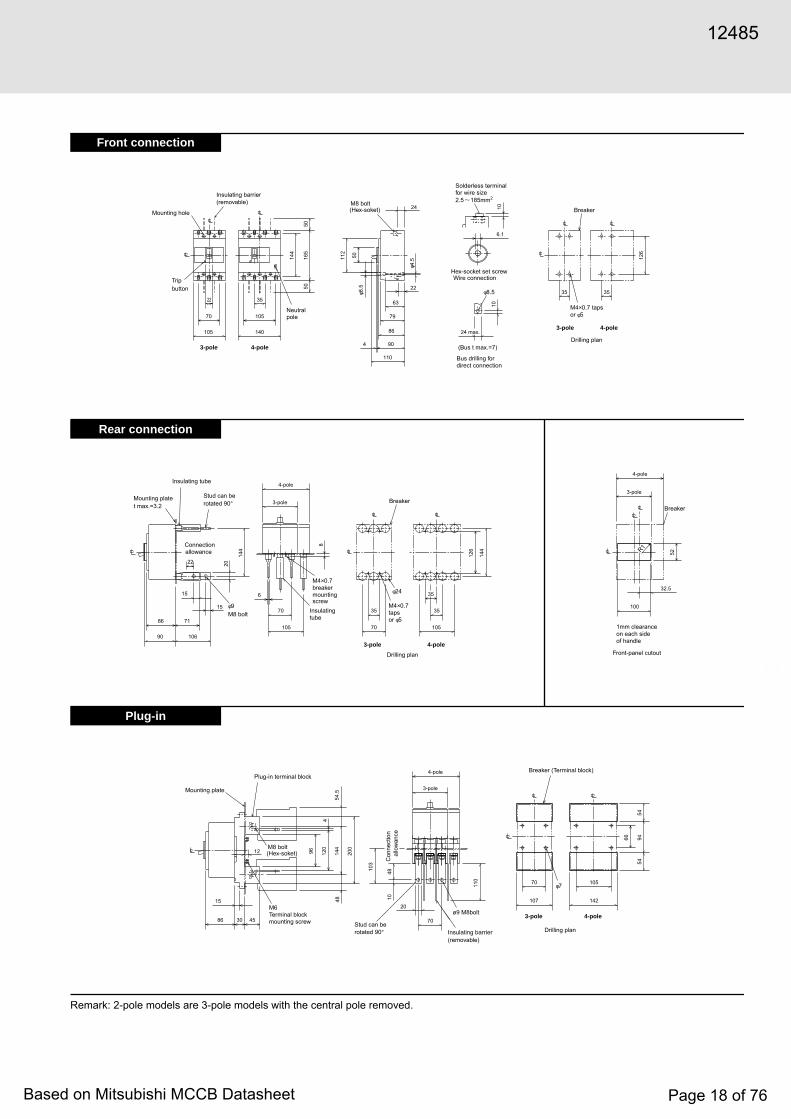
Front connection
Rear connection
Plug-in
Remark: 2-pole models are 3-pole models with the central pole removed.
Mounting plate
4530Stud can berotated 90°
5454
9466
4-pole
3-pole
110
104810
3
M8 bolt(Hex-soket)12 96
4
4854
.514
4
120
15
200
4-pole3-poleø9 M8bolt
105
142
Drilling plan
Con
nect
ion
al
low
ance
Insulating barrier(removable)
M6Terminal blockmounting screw
Breaker (Terminal block)
φ7
Plug-in terminal block
107
70
70
20
86
3-pole
4-pole
100
52
32.5
Breaker
1mm clearanceon each sideof handle
Front-panel cutout
R1
35
90
86
Breaker
4-pole3-pole
144
126
35
105
35
70
105
6
8
3-pole
4-pole
Insulatingtube
M4×0.7tapsor φ5
Drilling plan
106
71
φ24
M4×0.7breakermountingscrew
φ9M8 bolt
Connectionallowance
Insulating tube
Stud can berotated 90°
Mounting plate t max.=3.2
70
144
2022
15
15
Hex-socket set screwWire connection
Solderless terminalfor wire size2.5 185mm2
10
6.1
2235
24 max.
110
90
86
79
63
112
4-pole3-pole
Neutralpole
4-pole3-pole
144
165
5050
35
105
140
126
35φ8.5
(Hex-soket)
φ4.5
M4×0.7 tapsor φ5
Drilling plan
BreakerM8 bolt
(Bus t max.=7)
Bus drilling fordirect connection
Tripbutton
Mounting hole
Insulating barrier(removable)
φ8.5
10
22
70
24
4
50
105
12485
Based on Mitsubishi MCCB Datasheet Page 18 of 76
F—
S
V 60
64
75
Small TC-S
66
Large TC-L
Rear BTC
—
Skeleton TTC
Plug-in PTC
LC
(*2)HL
HL-S
MI
76
TCS-2GSW3W (*1)
TCL-2GSW3W (*1)
BTC-2GSW3W (*1)
PTC-2GSW3W (*1)
TTC-2GSW3 (*1)
LC-2GSW
HLN-2GSW
HLF-2GSW
HLS-2GSW
V2GUW
R R2GUW
—
—
—
MI-05SW3 (*1)
AL AX
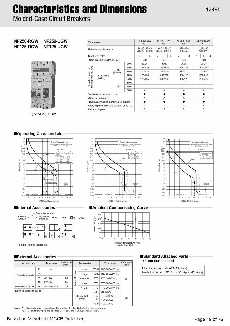
NF250-RGWNF125-RGW
NF250-UGWNF125-UGW
Rat
ed s
hort-
circ
uit
brak
ing
capa
city
(kA
)
Rated current In (Amp.)
Number of poles
IEC60947-2(Icu/Ics)
AC(50/60Hz)
DC
Rated insulation voltage Ui (V)
Suitability for isolationUtilization categoryReverse connection (terminals unmarked)Rated impulse withstand voltage Uimp (kV)Pollution degree
Type name
32
69025/25
125/125125/125125/125125/125
–––●
A●
83
NF125-RGWRT
16–25 25–4040–63 63–100
16–25 25–4040–63 63–100
32 2 3 4
69025/25
125/125125/125125/125125/125
–––●
A●
83
●
A●
83
69030/30
200/200200/200200/200200/200
–––
NF250-RGWRT
NF250-UGWRT
125–160160–225
125–160160–225
2 3 4
●
A●
83
69030/30
200/200200/200200/200200/200
–––
NF125-UGWRT
690V500V440V400V230V300V500V600V
■ Operating Characteristics
■ Internal Accessories
■ Standard Attached Parts(Front connection)
Mounting screw: M4×0.7×73 (4pcs)Insulation barrier: (2P : 2pcs, 3P : 4pcs, 4P : 6pcs)
■ External Accessories
Term
inal
cov
er
Left-sidemounting
Right-sidemounting
Operating handle
SHT or UVT
Remark: (1) refer to page 50.
Type name Type nameAccessories AccessoriesReferencepage
Referencepage
Operating handle
Mechanical interlock
Electrical operation device
Handle lockdevice
Notes: (*1) The designation depends on the number of poles. Refer to the reference page.(*2) HLF and HLS types are used for OFF-lock, and HLN types for ON-lock.
■ Ambient Compensating Curve
×100% of Rated current
Ope
ratin
g tim
e
4h
2h
1h
30min 20min 14min 10min
6min 4min
2min
1min
30s20s
10s
5s
2s
1s
0.5s
0.2s
0.1s
0.05s
0.02s
1 1.3 2 3 4 5 6 7 10 15 20 30 400.01s
×100% of Rated current ×100% of Rated current
Ope
ratin
g tim
e
4h
2h
1h
30min 20min 14min 10min
6min 4min
2min
1min
30s20s
10s
5s
2s
1s
0.5s
0.2s
0.1s
0.05s
0.02s
1 1.3 2 3 4 5 6 7 10 15 20 30 400.01s
Ope
ratin
g tim
e
4h
2h
1h
30min 20min 14min 10min
6min 4min
2min
1min
30s20s
10s
5s
2s
1s
0.5s
0.2s
0.1s
0.05s
0.02s
1 1.3 2 3 4 5 6 7 10 15 20 30 400.01s
1300±2601040
780
DC x In (%)520±104
AC x In (%)
1000±200800600400±80
10864
Positionof notch
Instantaneous trip adjustmentrange
Min.
breakingMax. total
Max.
time
NF250-RGW/UGW 160-225A (Rated current In=225A) 125-160A (Rated current In=160A)
IEC 60947-2
Thermal-Adjustable types
Time-delay trip Instantaneous trip
DC(Adjustable range)
AC(Adjustable range)
1300±260
DC x In (%)
Instantaneous tripcurrent ratio
1000±200
AC x In (%)
40-63A (Rated current In=63A)NF125-RGW/UGW 63-100A (Rated current In=100A)
time
Max.
Max. totalbreaking
Min.
DC
AC
IEC 60947-2
Thermal-Adjustable types
Time-delay trip Instantaneous trip
1000±200 1300±260
AC x In (%)
DC x In (%)
Instantaneous tripcurrent ratio
time
Max.
Max. totalbreaking
Min.
NF125-RGW/UGW 25-40A (Rated current In=40A) 16-25A (Rated current In=25A)
DC
AC
IEC 60947-2
Thermal-Adjustable types
Time-delay trip Instantaneous trip
130
120
110
100
90
800 10 20 30 40 50 60
(rated ambient 40°C)Ambient temperature (°C)
Rate
d am
bien
t
Cur
rent
ratin
g (%
)
–10
Type NF250-UGW
Characteristics and DimensionsMolded-Case Circuit Breakers
12485
Based on Mitsubishi MCCB Datasheet Page 19 of 76

Front connection
Rear connection
Plug-in
φ7
Insulatingbarrier
Drilling plan
Mounting plate
Stud attachable in thisderection only φ9 M8bolt
(Terminal block)
Con
nect
ion
allo
wan
ce
M6Terminal blockmounting screw
BreakerPlug-in terminalblock
275
34.5
219
28
6
32
18
14
104
22
15
70
20
70
153
70
58.5
58.5
155
129
107
100
32.5
52
4-pole
3-pole
R1
Breaker
1mm clearanceon each sideof handle
Front-panel cutout
11.5
105
35
35
70
35
4-pole
3-pole
8
105
70
6
20
15
15
90 106
7186
4-pole3-pole
Insulatingtube
M4×0.7tapsor φ5
Drilling plan
ø24
M4×0.7breakermountingscrewφ9
M8 bolt
Connectionallowance
Insulating tube
Stud can berotated 90°
Mounting plate t max.=3.2
201
219
219
108
73
22
Breaker
24
(Bus t max.=7)
24 max.
10
(Hex-soket)M8 bolt
M4×0.7 tapsor φ5
3535
110
4 90
86
79
φ8.5
63
22
φ4.55011
2
4-pole
5050
35
105
140
22
70
1054-pole3-pole
Neutralpole
3-poleDrilling plan
Breaker
Tripbutton
Mounting hole
Insulating barrier(removable)
201
240
219
φ8.5
6.1
Solderless terminalfor wire size2.5 185mm2
10
Bus drilling fordirect connection
Wire connectionHex-socket set screw
26.5
7516
5
Remark: 2-pole models are 3-pole models with the central pole removed.
12485
Based on Mitsubishi MCCB Datasheet Page 20 of 76

NF400-CPNF400-SP
Type NF400-SP
■ Operating Characteristics
■ Internal Accessories ■ Ambient Compensating Curve
130
120
110
100
90
800 10 20 30 40 50 60
AL
(*1) (*1)(*1)
(*1)
AX SHT or UVT
1000.01s
1min
1h
0.02s
0.05s
0.1s
0.2s
0.5s
1s
2s
5s
10s
20s30s
2min
4min6min
10min14min20min30min
2h
4h
130 200 300 400500
600700
1000 15002000
30004000
Operating Characteristics
(IEC 60947-2)
NF400-CP
NF400-SP
×100% of Rated current
Ope
ratin
g tim
e
Instantaneous tripTime-delay trip
Max. total breaking time
Max
NF400-CP
NF400-SP
Min
Type nameRated current In (Amp.)Number of poles
Rated insulationvoltage Ui (V)
Rat
ed s
hort-
circ
uit
brea
king
cap
acity
(kA)
600
–15/8
25/1336/1850/25
690
10/1030/3042/4245/4585/85
2 2 3 43
250 – 250 –
Note: (1)Types of DC specifications can be produced upon request.
IEC 60947-2(Icu/Ics)
AC
DC
ACDC(*1)690V500V440V400V230V250V 40/40 –20/10 –
NF400-CP NF400-SP
250 300 350 400
Left-sidemounting
Right-sidemounting
Operating handle
Note: (*1) Right-side mounting is standard of SHT and UVT. Specify separately for left-side mounting.Remark: (1) refer to page 51.
Lead wiredirection
Refe
renc
e am
bien
tte
mpe
ratu
re
Ambient temperature (°C)(Reference ambient temperature 40°C)
Cur
rent
ratin
g (%
)
■ External Accessories
Note: (*1) The designation depends on the number of poles. Refer to the reference page.
Accessories
Operating handle
F
S
V
61
63
60
75
76
66
76
67
F4SPW
S4CP, S4SP
V4SPWF, V4SPW
MI-4SP3 (*1)
HT-4CP, HT4SP
Term
inal c
over Large
Skeleton
Rear
Electrical operation device
TCL-4SP3W (*1)
TTC-4SP3 (*1)
BTC-4SP3W (*1)
HL-4CP, HL-4SP
HLS-4SP
(MI)
(HT)
(TC-L)
(TTC)
(BTC)HL
HL-SMechanical interlock
Auxiliary handle
Handlelock device
Type name Referencepage Accessories Type name Reference
page
■ Standard Attached Parts(An order for should be placed at the same time as an order of circuit breaker main body.)
Front connection
Rear connection
Mounting screw: M6 × 60 (4pcs)Insulating barrier: (2P: 2pcs, 3P: 4pcs, 4P: 6pcs)
Mounting screw: M6 × 72 (4pcs)
Characteristics and DimensionsMolded-Case Circuit Breakers
12485
Based on Mitsubishi MCCB Datasheet Page 21 of 76

Front connection
Rear connection
Plug-in
Remark: (1) 2-pole models are 3-pole models with the central pole removed.
28
87
130.5
136
44
160
79
15
24
121
18
24280
3528
225
8
181
87
135
163
5555
R6
113
10
25
118
92
20 20
26
225
265
87
44
43.5
130.5
44
194
225
8
8
87
130.5
128 83
14
102
3939
ø12
.5
ø7
155 (NF400-SP)134 (NF400-CP)
107
103
97
44
844
94.5
5
47
12
25ø10.5
44 44
194
110 16
4325
7
51
112
140
28
185
196
168
56
4-pole3-pole
Breaker
Drilling plan
M6 tap or ø7
Conductor thickness t=8 max.Conductor drilling for
direct connection
Conductor thickness t=8 max.
Neutral pole
4-pole3-pole
Trip button
Insulating barrier (removable)
Mounting hole
ø14 M12 bolt
ø13M12 bolt
Mounting plate
Stud can be rotated 90°
Connectionallowance
4-pole
3-pole
Insulation tube
M6 screw formounting breaker ø35
4-pole3-pole
M6 tap or ø7
Breaker Groove for reducingheat by overcurrent
Drilling plan
4-pole
3-pole
Breaker
Front-panel cutout
1.0mm clearance on each side of thehandle frame.
Mounting plate Plug-in terminal block
M8 terminal blockmounting screw
Stud attachable in this direction only
Insulating barrier
Connection allowance
ø13M12 bolt
4-pole
3-pole
3-pole 4-pole
ø10
Drilling plan
Breaker
248
194
225
2424
24
11 11
6-ø35
87
44
Load side
Note:
Line side
Boring dimensions for rear connection type barriers (3-pole)
The bore dimensional drawing shows the breaker viewed from the rear.
4-M6 tap or ø7
8-M4 screw Add these tapped holes in 8 positions to standard boring.
12485
Based on Mitsubishi MCCB Datasheet Page 22 of 76

NF400-SEPNF400-HEPNF400-REP
Type NF400-SEP
■ Operating Characteristics
■ Internal Accessories ■ Temperature Characteristics
Ambient temperature (°C)
Rat
ed a
mbi
ent
80
70
90
100
110
120
130
0 10 20 30 40 50 60
Con
tinuo
us lo
ad c
urre
nt (%
)
LTD operating timeat 125%
1000s(TL=150s set) 670s(TL=100s set) 400s(TL= 60s set) 80s(TL= 12s set)
0.6 0.7 1 1.3 2 3 4 5 6 7 10 30 4020150.01s
0.02s
0.05s
0.1s
0.2s
0.5s
1s
2s
5s
10s
20s30s
1min
2min
4min6min
10min14min20min30min
1h
2h
5h
10h
Pre-alarmpickup current IpIr x(0.70-0.75-0.8-0.85-0.9 ±10%-0.95-1.0)
Pre-alarmoperating time Tp
±20%
(at 200%)
Tp=2TL
Ope
ratin
g tim
e
INST pickup current IIx4~x16 ±15%
(Magnification to In)Max. totalbreaking time
STD operating time Ts
STD pickup current Is
12-60-100-150s ±20%(at 200%)
Ir x(2-2.5-3-3.5-4 -5-6-7-8-10) ±15%
0.3 ± 0.06s0.2 ± 0.04s
0.1 ± 0.03s0.06 ± 0.02s
LTD operating time TL
NF400-SEPNF400-HEPNF400-REP
Note)Current setting Ir: 200~400A (Adjustable)
Rated Current In: 400A
Current setting (×100% of Ir)Instantaneous tripping current (×100% of In)
■ External Accessories
Notes: (*1) This is for NF400-SEP.(*2) The designation depends on the number of poles. Refer to the reference page.
Accessories
Operating handle
F
S
V
61
63
60
75
76
66
76
67
F4SPW
S4SP
V4SPWF, V4SPW
MI-4SP3 (*2)
HT-4SP
Term
inal c
over Large
Skeleton
Rear
Electrical operation device
TCL-4SP3W (*1)(*2)
TTC-4SP3 (*2)
BTC-4SP3W (*1)(*2)
HL-4SP
HLS-4SP
(MI)
(HT)
(TC-L)
(TTC)
(BTC)HL
HL-S
Mechanical interlock
Auxiliary handleHandlelock device
Type name Referencepage Accessories Type name Reference
page
(An order for should be placed at the same time as an order of circuit breaker main body.)■ Standard Attached Parts
Front connection
Rear connection
Mounting screw: M6 × 60 (4pcs)Insulating barrier: (2P: 2pcs, 3P: 4pcs, 4P: 6pcs)
Mounting screw: M6 × 72 (4pcs)
Type name
Rated current In (Amp.)
Number of polesReted insulation voltage Ui (V)
Rat
ed s
hort-
circ
uit
brea
king
cap
acity
(kA)
69010/1030/3042/4245/4585/85
—
69010/1050/5065/6570/70
100/100—
69015/1070/35
125/63125/63150/75
—
43 43 3
IEC 60947-2(Icu/Ics)
AC
DC
AC690V500V440V400V230V250V
NF400-SEP NF400-HEP NF400-REP
200-400adjustable
SHT or UVTAL AX PAL TI
(*1) (*1) (*1)
(*1)
Left-sidemounting
Right-sidemounting
Operating handleLead wiredirection
Note: (*1) Right-side mounting is standard of SHT and UVT. Specify separately for left-side mounting.Remark: (1) refer to page 51.
Characteristics and DimensionsMolded-Case Circuit Breakers
12485
Based on Mitsubishi MCCB Datasheet Page 23 of 76

Front connection
Rear connection
Plug-in
28
87
130.5
136
44
160
79
15
24
121
18
24280
3528
225
8
181
87
135
163
5555
R6
113
10
25
118
92
20 20
26
225
265
87
44
43.5
130.5
44
194
225
8
8
87
130.5
128 83
14
102
3939
ø12
.5
ø7
155
107
103
97
44
844
94.5
5
47
12
25ø10.5
44 44
194
110 16
4325
7
51
112
140
28
185
196
168
56
4-pole3-pole
Breaker
Drilling plan
M6 tap or ø7
Conductor thickness t=8 max.Conductor drilling for
direct connection
Conductor thicknesst=8 max.
Neutral pole
4-pole3-pole
Trip button
Insulating barrier (removable)
Mounting hole
ø14M12 bolt
ø13M12 bolt
Mounting plate Stud can be rotated 90°
Connectionallowance
4-pole
3-pole
Insulation tube
M6 screw for mounting breaker ø35
4-pole3-pole
M6 tap or ø7
Breaker
Groove for reducing heat by overcurrent
Drilling plan
4-pole
3-pole
Breaker
Front-panel cutout
1.0mm clearance on each side of the handle frame.
Mounting plate Plug-in terminal block
M8 terminal block mounting screw
Stud attachable in this direction only
Insulating barrier
Connectionallowance
ø13M12 bolt
4-pole
3-pole
3-pole 4-pole
ø10
Drilling plan
Breaker
248
194
225
2424
24
11 11
6-ø35
87
44
Load side
Note:
Line side
Boring dimensions for rear connectiontype barriers (3-pole)
The bore dimensional drawing shows the breaker viewed from the rear.
4-M6 tap or ø7
8-M4 screw Add these tapped holes in 8 positions to standard boring.
12485
Based on Mitsubishi MCCB Datasheet Page 24 of 76
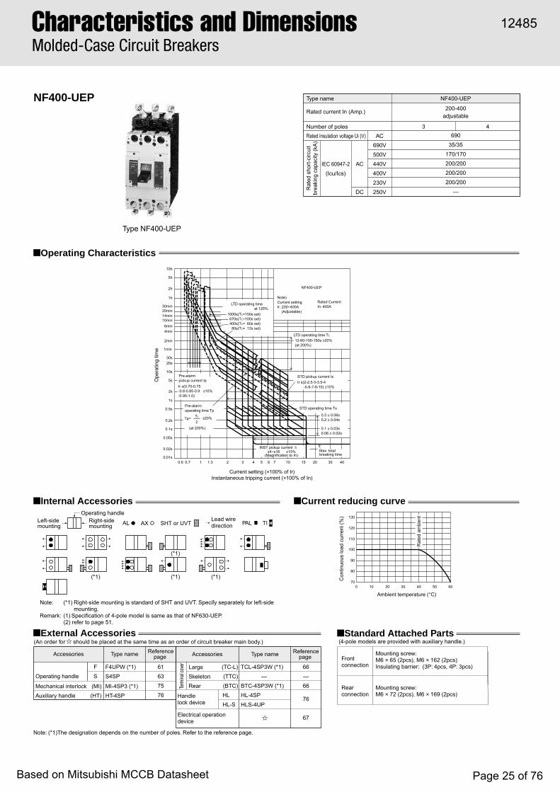
NF400-UEP
■ Operating Characteristics
■ Internal Accessories ■ Current reducing curve
Type name
Rated current In (Amp.)
Number of polesRated insulation voltage Ui (V)
Rat
ed s
hort-
circ
uit
brea
king
cap
acity
(kA)
69035/35
170/170200/200200/200200/200
—
3 4
IEC 60947-2(Icu/Ics)
AC
DC
AC690V500V440V400V230V250V
NF400-UEP
200-400adjustable
Ambient temperature (°C)
Rat
ed a
mbi
ent
80
70
90
100
110
120
130
0 10 20 30 40 50 60
Con
tinuo
us lo
ad c
urre
nt (%
)
Current setting (×100% of Ir)Instantaneous tripping current (×100% of In)
LTD operating timeat 125%
1000s(TL=150s set) 670s(TL=100s set) 400s(TL= 60s set) 80s(TL= 12s set)
0.6 0.7 1 1.3 2 3 4 5 6 7 10 30 4020150.01s
0.02s
0.05s
0.1s
0.2s
0.5s
1s
2s
5s
10s
20s30s
1min
2min
4min6min
10min14min20min30min
1h
2h
5h
10h
Pre-alarmpickup current IpIr x(0.70-0.75-0.8-0.85-0.9 ±10%-0.95-1.0)
Pre-alarmoperating time Tp
±20%
(at 200%)
Tp=2TL
Ope
ratin
g tim
e
INST pickup current IIx4~x16 ±15%
(Magnification to In)Max. totalbreaking time
STD operating time Ts
STD pickup current Is
12-60-100-150s ±20%(at 200%)
Ir x(2-2.5-3-3.5-4 -5-6-7-8-10) ±15%
0.3 ± 0.06s0.2 ± 0.04s
0.1 ± 0.03s0.06 ± 0.02s
LTD operating time TL
NF400-UEP
Note)Current setting Ir: 200~400A (Adjustable)
Rated Current In: 400A
■ External Accessories
Note: (*1)The designation depends on the number of poles. Refer to the reference page.
Accessories
Operating handle
F
S61
63
75
76
66
—
66
76
67
F4UPW (*1)
S4SP
MI-4SP3 (*1)
HT-4SP
Term
inal c
over Large
Skeleton
Rear
Electrical operation device
TCL-4SP3W (*1)
—
BTC-4SP3W (*1)
HL-4SP
HLS-4UP
(MI)
(HT)
(TC-L)
(TTC)
(BTC)HL
HL-S
Mechanical interlock
Auxiliary handle Handlelock device
Type name Referencepage Accessories Type name Reference
page
(An order for should be placed at the same time as an order of circuit breaker main body.)■ Standard Attached Parts
Front connection
(4-pole models are provided with auxiliary handle.)
Rear connection
Mounting screw: M6 × 65 (2pcs), M6 × 162 (2pcs)Insulating barrier: (3P: 4pcs, 4P: 3pcs)
Mounting screw: M6 × 72 (2pcs), M6 × 169 (2pcs)
Type NF400-UEP
SHT or UVTAL AX PAL TI
(*1) (*1) (*1)
(*1)
Left-sidemounting
Right-sidemounting
Operating handleLead wiredirection
Note: (*1) Right-side mounting is standard of SHT and UVT. Specify separately for left-side mounting.
Remark: (1) Specification of 4-pole model is same as that of NF630-UEP. (2) refer to page 51.
Characteristics and DimensionsMolded-Case Circuit Breakers
12485
Based on Mitsubishi MCCB Datasheet Page 25 of 76
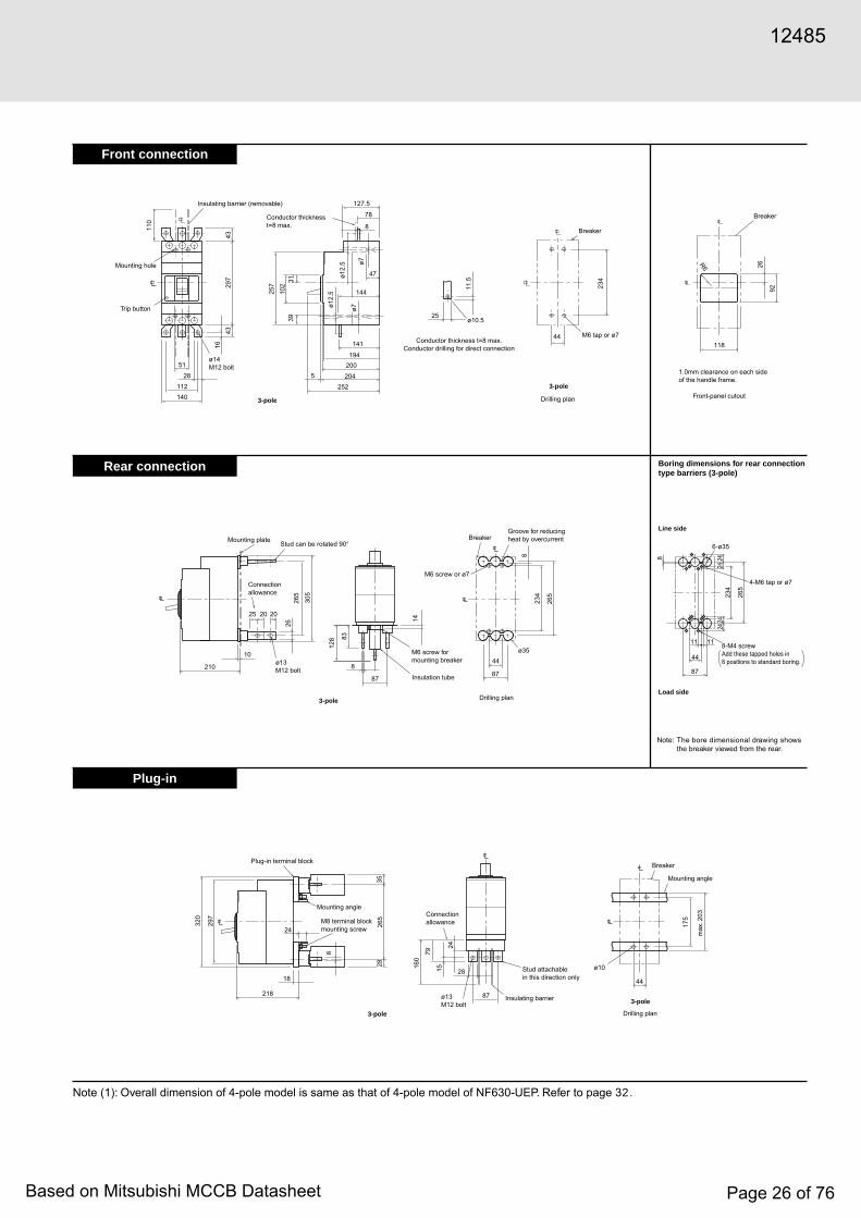
Front connection
Rear connection
Plug-in
Note (1): Overall dimension of 4-pole model is same as that of 4-pole model of NF630-UEP. Refer to page .
1643
297
102
39
257
ø12.
5
ø12.
5
11.5
234
ø7ø7
31
110
43
51
28112140
252204
200194
141
144
25
47
8
78
127.5
5
44
218
1828
87
44
24
320
297
3528
265
160
79
175
15
24
8
R6
210
10
25
8
8787
118
44
20 20
2626
5
305
128
234
26
92
265
8
83
14
3-pole
3-pole
Trip button
Insulating barrier (removable)
Mounting hole
ø14M12 bolt
ø10.5
Conductor thickness t=8 max.Conductor drilling for direct connection
Conductor thickness t=8 max.
3-pole
Breaker
Drilling plan
M6 tap or ø7
ø13M12 bolt
Mounting plate Stud can be rotated 90°
Connectionallowance
Insulation tube
M6 screw for mounting breaker
ø35
M6 screw or ø7
BreakerGroove for reducing heat by overcurrent
Drilling plan
Breaker
Front-panel cutout
1.0mm clearance on each side of the handle frame.
3-pole
ø10
3-pole
Drilling plan
Mounting angle
Mounting angle
Plug-in terminal block
M8 terminal block mounting screw
Stud attachable in this direction only
Insulating barrier
Connection allowance
ø13M12 bolt
Breaker
max
. 203
248
234
265
2424
24
11 11
6-ø35
87
44
Load side
Note:
Line side
Boring dimensions for rear connection type barriers (3-pole)
The bore dimensional drawing shows the breaker viewed from the rear.
4-M6 tap or ø7
8-M4 screw Add these tapped holes in 8 positions to standard boring.
12485
Based on Mitsubishi MCCB Datasheet Page 26 of 76
32
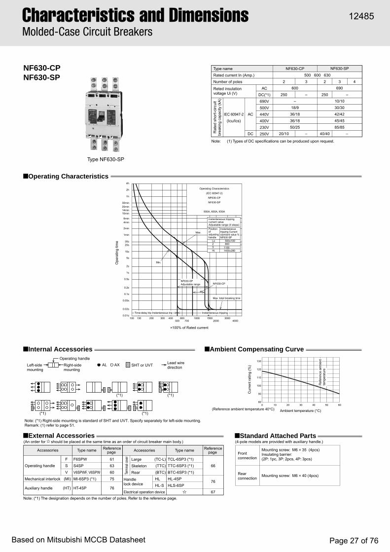
NF630-CPNF630-SP
Type NF630-SP
■ Operating Characteristics
■ Internal Accessories ■ Ambient Compensating Curve
Ambient temperature (°C)
Cur
rent
ratin
g (%
)
Type nameRated current In (Amp.)Number of poles
Reted insulationvoltage Ui (V)
Rat
ed s
hort-
circ
uit
brea
king
cap
acity
(kA)
600
–18/9
36/1836/1850/25
690
10/1030/3042/4245/4585/85
2 2 3 43
250 – 250 –
Note: (1) Types of DC specifications can be produced upon request.
IEC 60947-2(Icu/Ics)
AC
DC
ACDC(*1)690V500V440V400V230V250V 40/40 –20/10 –
NF630-CP NF630-SP
500 600 630
1000.01s
1min
1h
0.02s
0.05s
0.1s
0.2s
0.5s
1s
2s
5s
10s
20s30s
2min
4min6min
10min14min20min30min
2h
4h
130 200 300 400500
600700
1000 15002000
30004000
×100% of Rated current
Ope
ratin
g tim
e
Operating Characteristics
(IEC 60947-2)
NF630-CP
NF630-SP
500A, 600A, 630A
Instantaneous tripping
Max. total breaking time
Max.
Min.
Time-delay trip Instantaneous trip
NF630-SP Adjustable range NF630-CP
Note: (*1) The designation depends on the number of poles. Refer to the reference page.
■ External Accessories
Accessories
Operating handle
F
S
V
61
63
60
75
76
66
76
67
F6SPW
S4SP
V6SPWF, V6SPW
MI-6SP3 (*1)
HT-4SP
Term
inal c
over Large
Skeleton
Rear
Electrical operation device
TCL-6SP3 (*1)
TTC-6SP3 (*1)
BTC-6SP3 (*1)
HL-4SP
HLS-6SP
(MI)
(HT)
(TC-L)
(TTC)
(BTC)HL
HL-SMechanical interlock
Auxiliary handle
Handlelock device
Type name Referencepage Accessories Type name Reference
page
(An order for should be placed at the same time as an order of circuit breaker main body.) (4-pole models are provided with auxiliary handle.)■ Standard Attached Parts
Front connection
Rear connection
Mounting screw: M6 × 35 (4pcs)Insulating barrier: (2P: 1pc, 3P: 2pcs, 4P: 3pcs)
Mounting screw: M6 × 40 (4pcs)
AL
Note: (*1) Right-side mounting is standard of SHT and UVT. Specify separately for left-side mounting. Remark: (1) refer to page 51.
Right-side mounting
(*1)
(*1) (*1)
Left-side mounting
Operating handleAX SHT or UVT Lead wire
direction
(*1)
130
120
110
100
90
800
(Reference ambient temperature 40°C)10 20 30 40 50 60
Ref
eren
ce a
mbi
ent
tem
pera
ture
Instantaneous tripping current valueAdjustable range (4 steps)Position of adjusting handle
Instantaneous tripping Current standard value %NF630-SP
Lo23Hi
500±100800
11001400±280
Characteristics and DimensionsMolded-Case Circuit Breakers
12485
Based on Mitsubishi MCCB Datasheet Page 27 of 76
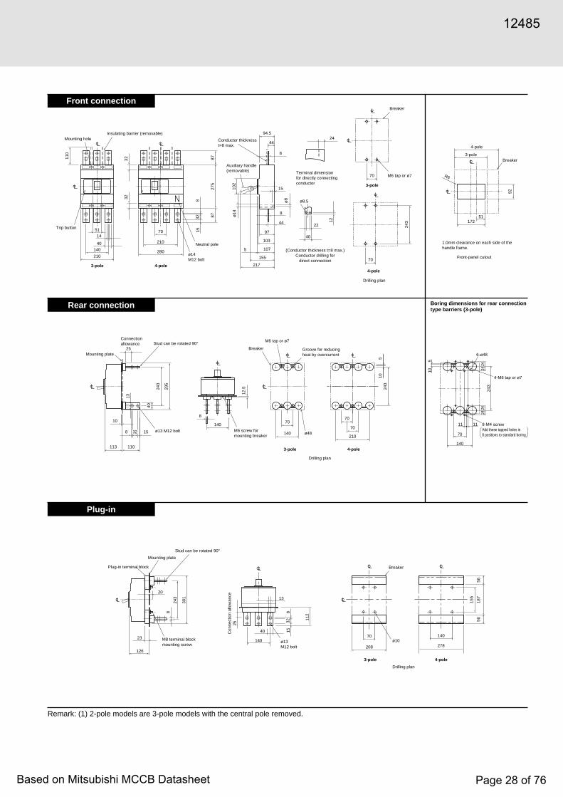
Front connection
Rear connection
Plug-in
Remark: (1) 2-pole models are 3-pole models with the central pole removed.
140
210
70
210280
110
14
40
51
32 815
32
275
87
97
103
107
87
32
94.5
8
4424
8
44
102
15
22
40
ø8.5
5
ø14
155
217
12
70
70
243
243
295
243
70
140
40
25
13
8 15
113 110
140
32
10
12.5
70
70
210
105
17251
92
R6
8
208
70
278
140
155
5656
18713
40
140
3225
815
112
243
8
20
301
126
23
Neutral pole
4-pole3-pole
Trip button
Insulating barrier (removable)Mounting hole
ø14M12 bolt
ø8
Conductor thickness t=8 max.
(Conductor thickness t=8 max.)Conductor drilling for
direct connection
Auxiliary handle (removable) Terminal dimension
for directly connecting conductor
4-pole
3-pole
Breaker
Drilling plan
M6 tap or ø7
4-pole
3-pole Breaker
Front-panel cutout
1.0mm clearance on each side of the handle frame.
ø48
4-pole3-pole
M6 tap or ø7
Breaker Groove for reducing heat by overcurrent
Drilling plan
M6 screw for mounting breaker
ø13 M12 bolt
Mounting plate
Stud can be rotated 90°Connection allowance
Mounting plate
Plug-in terminal block
M8 terminal block mounting screw
Stud can be rotated 90°
Con
nect
ion
allo
wan
ce
ø13M12 bolt
3-pole 4-pole
ø10
Drilling plan
Breaker
2424
2424
11 11
140
70
243
6-ø48
510
Boring dimensions for rear connection type barriers (3-pole)
4-M6 tap or ø7
8-M4 screw Add these tapped holes in 8 positions to standard boring.
12485
Based on Mitsubishi MCCB Datasheet Page 28 of 76

NF630-SEPNF630-HEPNF630-REP
Type NF630-SEP
■ Operating Characteristics
■ Internal Accessories ■ Temperature Characteristics
Ambient temperature (°C)
Rat
ed a
mbi
ent
80
70
90
100
110
120
130
0 10 20 30 40 50 60
Con
tinuo
us lo
ad c
urre
nt (%
)
Instantaneous tripping current (×100% of In)Current (×100% of Ir)
LTD operating timeat 125%
1000s(TL=150s set) 670s(TL=100s set) 400s(TL= 60s set) 80s(TL= 12s set)
0.6 0.7 1 1.3 2 3 4 5 6 7 10 30 4020150.01s
0.02s
0.05s
0.1s
0.2s
0.5s
1s
2s
5s
10s
20s30s
1min
2min
4min6min
10min14min20min30min
1h
2h
5h
10h
Pre-alarmpickup current IpIr x(0.70-0.75-0.8-0.85-0.9 ±10%-0.95-1.0)
Pre-alarmoperating time Tp
±20%
(at 200%)
Tp=2TL
Ope
ratin
g tim
e
INST pickup current IIx4~x15 ±15%
(Magnification to In)Max. totalbreaking time
STD operating time Ts
STD pickup current Is
12-60-100-150s ±20%(at 200%)
Ir x(2-2.5-3-3.5-4 -5-6-7-8-10) ±15%
0.3 ± 0.06s0.2 ± 0.04s
0.1 ± 0.03s0.06 ± 0.02s
LTD operating time TL
NF630-SEPNF630-HEPNF630-REP
Note)Current setting Ir: 300~630A (Adjustable)
Rated Current In: 630A
Type name
Rated current In (Amp.)
Number of polesReted insulation voltage Ui (V)
Rat
ed s
hort-
circ
uit
brea
king
cap
acity
(kA)
69010/1030/3042/4245/4585/85
—
69015/1550/5065/6570/70
100/100—
69020/1570/35
125/63125/63150/75
—
43 43 3
IEC 60947-2(Icu/Ics)
AC
DC
AC690V500V440V400V230V250V
NF630-SEP NF630-HEP NF630-REP
300-630adjustable
Note: (*1) The designation depends on the number of poles. Refer to the reference page.
■ External Accessories
Accessories
Operating handle
F
S
V
61
63
60
75
76
66
76
67
F6SPW
S4SP
V6SPWF, V6SPW
MI-6SP3 (*1)
HT-4SP
Term
inal c
over Large
Skeleton
Rear
Electrical operation device
TCL-6SP3 (*1)
TTC-6SP3 (*1)
BTC-6SP3 (*1)
HL-4SP
HLS-6SP
(MI)
(HT)
(TC-L)
(TTC)
(BTC)HL
HL-S
Mechanical interlock
Auxiliary handleHandlelock device
Type name Referencepage Accessories Type name Reference
page
(An order for should be placed at the same time as an order of circuit breaker main body.) (4-pole models are provided with auxiliary handle.)■ Standard Attached Parts
Front connection
Rear connection
Mounting screw: M6 × 35 (4pcs)Insulating barrier: (3P: 2pcs, 4P: 3pcs)
Mounting screw: M6 × 40 (4pcs)
SHT or UVTAL AX PAL TILeft-sidemounting
Right-sidemounting
Operating handleLead wiredirection
Note: (*1) Right-side mounting is standard of SHT and UVT. Specify separately for left-side mounting.Remark: (1) refer to page 51.
(*1) (*1)
(*1)(*1)
Characteristics and DimensionsMolded-Case Circuit Breakers
12485
Based on Mitsubishi MCCB Datasheet Page 29 of 76

Front connection
Rear connection
Plug-in
140
210
70
210280
110
14
40
51
32 815
32
275
87
97
103
107
87
32
94.5
8
4424
8
4410
2
15
22
40
ø8.5
5
ø14
155
217
12
70
70
243
243
295
243
70
140
40
25
13
8 15
113 110
140
32
10
12.5
70
70
210
105
17251
92
R6
8
208
70
278
140
155
5656
18713
40
140
3225
815
112
243
20
301
8
126
23
Neutral pole
4-pole3-pole
Trip button
Insulating barrier (removable)Mounting hole
ø14M12 bolt
N ø8
Conductor thickness t=8 max.
(Conductor thickness t=8 max.)Conductor drilling for
direct connection
Auxiliary handle (removable) Terminal dimension
for directly connecting conductor
4-pole
3-pole
Breaker
Drilling plan
M6 tap or ø7
Breaker
Front-panel cutout
1.0mm clearance on each side of the handle frame.
ø48
4-pole3-pole
M6 tap or ø7
Breaker Groove for reducing heat by overcurrent
Drilling plan
M6 screw for mounting breaker
ø13M12 bolt
Mounting plate
Stud can be rotated 90°Connection allowance
Mounting plate
Plug-in terminal block
M8 terminal block mounting screw
Stud can be rotated 90°
Con
nect
ion
allo
wan
ce
ø13M12 bolt
3-pole 4-pole
f10
Drilling plan
Breaker
4-pole
3-pole
2424
2424
11 11
140
70
243
6-ø48
510
Boring dimensions for rear connection type barriers (3-pole)
4-M6 tap or ø7
8-M4 screw Add these tapped holes in 8 positions to standard boring.
12485
Based on Mitsubishi MCCB Datasheet Page 30 of 76

NF630-UEP
■ Operating Characteristics
■ Internal Accessories ■ Temperature Characteristics
Ambient temperature (°C)
Rat
ed a
mbi
ent
80
70
90
100
110
120
130
0 10 20 30 40 50 60
Con
tinuo
us lo
ad c
urre
nt (%
)
LTD operating timeat-125%
1000s(TL=150s set) 670s(TL=100s set) 400s(TL= 60s set) 80s(TL= 12s set)
Pre-alarmpickup current IpIr x(0.70-0.75-0.8-0.85-0.9 ±10%-0.95-1.0)
Pre-alarmoperating time Tp
±20%
(at 200%)
Tp=2TL
INST pickup current IIx4~x15 ±15%
(Magnification to In)Max. totalbreaking time
STD operating time Ts
STD pickup current Is
12-60-100-150s ±20%(at 200%)
Ir x(2-2.5-3-3.5-4 -5-6-7-8-10) ±15%
0.3 ± 0.06s0.2 ± 0.04s
0.1 ± 0.03s0.06 ± 0.02s
LTD operating time TL
0.01s
0.02s
0.05s
0.1s
0.2s
0.5s
1s
2s
5s
10s
20s30s
1min
2min
4min6min
10min14min20min30min
1h
2h
5h
10h
Ope
ratin
g tim
e
NF630-UEP
Note)Current setting Ir: 300~630A (Adjustable)
Rated Current In: 630A
Instantaneous tripping current (×100% of In)Current (×100% of Ir)
0.6 0.7 1 1.3 2 3 4 5 6 7 10 30 402015
Type name
Rated current In (Amp.)
Number of polesReted insulation voltage Ui (V)
Rat
ed s
hort-
circ
uit
brea
king
cap
acity
(kA)
69035/35
170/170200/200200/200200/200
—
3 4
IEC 60947-2(Icu/Ics)
AC
DC
AC690V500V440V400V230V250V
NF630-UEP
300-630adjustable
■ External Accessories
Note: (*1) The designation depends on the number of poles. Refer to the reference page.
Accessories
Operating handleF
S61
63
75
76
66
—
66
76
67
F6UPW(*1)
S4SP
MI-6SP3 (*1)
HT-4SP
Term
inal c
over Large
Skeleton
Rear
Electrical operation device
TCL-6UP3 (*1)
—
BTC-6SP3 (*1)
HL-4SP
HLS-6UP
(MI)
(HT)
(TC-L)
(TTC)
(BTC)HL
HL-S
Mechanical interlock
Auxiliary handle Handlelock device
Type name Referencepage Accessories Type name Reference
page
(An order for should be placed at the same time as an order of circuit breaker main body.)■ Standard Attached Parts
Front connection
(4-pole models are provided with auxiliary handle.)
Rear connection
Mounting screw: 3P: M6 × 35, M6 × 132 (2pcs each)4P: M6 × 35 (3pcs), M6 × 132 (2pcs)Insulating barrier: (3P: 2pcs, 4P: 3pcs)
Mounting screw: 3P: M6 × 40, M6 × 137 (2pcs each)4P: M6 × 40 (3pcs), M6 × 137 (2pcs)
Type NF630-UEP
SHT or UVTAL AX
Note: (*1) Right-side mounting is standard of SHT and UVT. Specify separately for left-side mounting.
Remark: (1) refer to page 51.
PAL TILeft-sidemounting
Right-sidemounting
Operating handleLead wiredirection
(*1) (*1)
(*1)(*1)
Characteristics and DimensionsMolded-Case Circuit Breakers
12485
Based on Mitsubishi MCCB Datasheet Page 31 of 76
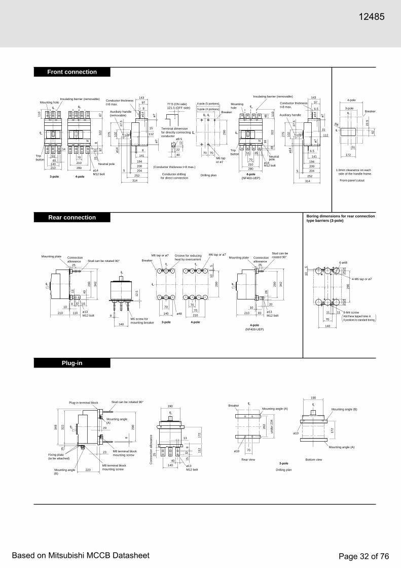
Front connection
Rear connection
Plug-in
140 210
70
N N
210 280
110
14
4051
815
322
87
194
141
200
204
87
32143
97
8
8
102
275
15
112
5
ø14
ø7
ø7ø14
252
314
70 70
290
210
70
3551
280
16
322
48
48 110
27.5
194
141
200
204
143
97
6.5
6.5
102
275
15
112
5
ø14
ø7
ø7ø14
252
314
27.5
22
40
ø8.5
12
290
290
342
70
140
40
25
13
8
8210 110
140
3210
12.5
70
70
210
105
172
51
92
22.5
15
290
342
2526
210 83
1020
8
20 290
322
348
25
223
23
(A)
(B)
13
40
140
190
32
25
815
112
172
202
unde
r 23
4
172
70ø10
ø10
190
Neutral pole
4-pole3-pole
Trip button
Insulating barrier (removable)Mounting hole
ø14M12 bolt
Conductor thickness t=8 max.
Conductor drilling for direct connection
(Conductor thickness t=8 max.)
Auxiliary handle(removable)
Terminal dimension for directly connecting conductor
4-pole(NF400-UEP)
4-pole(NF400-UEP)
Breaker
Mounting hole
Drilling plan
M6 tap or ø7
77.5 (ON side)121.5 (OFF side)
4-pole (5 portions)
3-pole (4 portions)
Neutral pole
Insulating barrier (removable)
ø14M12 bolt
Trip button
Conductor thickness t=8 max.
Auxiliary handle
ø13M12 bolt
Mounting plate
Stud can be rotated 90°Connection allowance
M6 screw for mounting breaker
ø48
4-pole3-pole
M6 tap or ø7 M6 tap or ø7
Breaker
Groove for reducing heat by overcurrent Mounting plate Connection
allowance
ø13M12 bolt
R6
4-pole
3-pole Breaker
Front-panel cutout
1.0mm clearance on each side of the handle frame.
Drilling plan
3-pole
Stud can be rotated 90°
Fixing plate (to be attached)
Mounting angle
Mounting angle
Plug-in terminal block
M8 terminal block mounting screw
M8 terminal block mounting screw
Con
nect
ion
allo
wan
ce
ø13M12 bolt
Mounting angle (A)Breaker
Rear view Bottom view
Mounting angle (A)
Mounting angle (B)
Stud can be rotated 90°
2424
2424
11 11
140
70
290
6-ø48
510
Boring dimensions for rear connection type barriers (3-pole)
4-M6 tap or ø7
8-M4 screw Add these tapped holes in 8 positions to standard boring.
12485
Based on Mitsubishi MCCB Datasheet Page 32 of 76

NF800-CEPNF800-SEPNF800-HEPNF800-REP
Type NF800-SEP
■ Operating Characteristics
■ Internal Accessories ■ Current Reducing Curve
Ambient temperature (°C)
80
70
90
100
110
120
130
0 10 20 30 40 50 60Wor
king
cur
rent
cor
rect
ing
ratio
(%)
Type name
Rated current In (Amp.)
Number of polesRated insulation voltage Ui (V)
Rate
d sh
ort-c
ircuit
bre
aking
ca
pacit
y (kA
)
600—
18/936/1836/1850/25
—
69010/1030/3042/4245/4585/85
—
3 3 4
IEC 60947-2(Icu/Ics)
NF800-CEP NF800-SEP
400-800adjustable
Note: (*1) The designation depends on the number of poles. Refer to the reference page.
Note: (*1) Right-side mounting is standard of SHT and UVT. Specify separately for left-side mounting.Remark: (1) refer to page 51.
■ External Accessories
Accessories
Operating handle
F
S
V
61
63
60
75
76
66
76
67
F6SPW
S4SP
V6SPWF, V6SPW
MI-6SP3 (*1)
HT-4SP
Term
inal c
over Large
Skeleton
Rear
Electrical operation device
TCL-6SP3 (*1)
TTC-6SP3 (*1)
BTC-6SP3 (*1)
HL-4SP
HLS-6SP
(MI)
(HT)
(TC-L)
(TTC)
(BTC)HL
HL-SMechanical interlock
Auxiliary handle
Handlelock device
Type name Referencepage Accessories Type name Reference
page
(An order for should be placed at the same time as an order of circuit breaker main body.) (4-pole models are provided with auxiliary handle.)■ Standard Attached Parts
Front connection
Rear connection
Mounting screw: M6 × 35 (4pcs)Insulating barrier: (3P: 2pcs, 4P: 3pcs)
Mounting screw: M6 × 40 (4pcs)
Ref
eren
ceam
bien
tte
mpe
ratu
re
The rated current does not depend on temperature. However, if ambient temperature exceeds 40°C, reduce the continuous working current as left curve.
LTD operating timeat 125%
1000s(TL=150s set) 670s(TL=100s set) 400s(TL= 60s set) 80s(TL= 12s set)
Pre-alarmpickup current IpIr x(0.70-0.75-0.8-0.85-0.9 ±10% -0.95-1.0)
Pre-alarmoperating time Tp
±20%
(at 200%)
Tp=2TL
INST pickup current IIx4~x12 ±15%
(Magnification to In)Max. totalbreaking time
STD operating time Ts
STD pickup current Is
12-60-100-150s ±20%(at 200%)
Ir x(2-2.5-3-3.5-4 -5-6-7-8-10) ±15%
0.3 ± 0.06s0.2 ± 0.04s
0.1 ± 0.03s0.06 ± 0.02s
LTD operating time TL
0.01s
0.02s
0.05s
0.1s
0.2s
0.5s
1s
2s
5s
10s
20s30s
1min
2min
4min6min
10min14min20min30min
1h
2h
5h
10h
Ope
ratin
g tim
e
Note)Current setting Ir: 400~800A (Adjustable)
Rated Current In: 800A
Instantaneous tripping current (×100% of In)Current (×100% of Ir)
0.6 0.7 1 1.3 2 3 4 5 6 7 10 30 402015
Operating Characteristics(IEC 60947-2)NF800-CEPNF800-SEPNF800-HEPNF800-REP
SHT or UVTAL AX PAL TILeft-sidemounting
Right-sidemounting
Operating handleLead wiredirection
(*1) (*1)
(*1)(*1)
69015/1550/5065/6570/70
100/100—
69020/1570/35
125/63125/63150/75
—
3 4 3AC
690V500V440V400V230V250V
NF800-HEP NF800-REP
AC
DC
Characteristics and DimensionsMolded-Case Circuit Breakers
12485
Based on Mitsubishi MCCB Datasheet Page 33 of 76

Front connection
Rear connection
Plug-in
140210
70
210 280
110
14
40
51
32 815
32
275
87
97
103
107
87
32
94.5
8
4626
8
4610
2
15
22
40
ø8.5
5
ø14
155
217
12 70 70
243
243
295
243
70
140
40
25
13
8 15
113 110
14032
10
12.5
70
70
210
105
172
51
92
R6
8
208
70
278
140
155
5656
187
13
40
140
3225
815
112
243
20
301
10
126
23
Neutral pole
4-pole3-pole
Trip button
Insulating barrier (removable)Mounting hole
ø14M12 bolt
N ø8
Conductor thicknesst=12 max.
(Conductor thickness t=10 max.)Conductor drilling for direct connection
Auxiliary handle(removable)
Terminal dimension for directly connecting conductor
4-pole3-pole
Breaker
Drilling plan
M6 tapor ø7
4-pole
3-poleBreake
Front-panel cutout
1.0mm clearance on eachside of the handle frame.
ø48
4-pole3-pole
M6 tap or ø7
Breaker Groove for reducingheat by overcurrent
Drilling plan
M6 screw formounting breaker
ø13M12 bolt
Mounting plate
Stud can be rotated 90°Connection allowance
Mounting plate
Plug-in terminal block
M8 terminal block mounting screw
Stud can be rotated 90°
Con
nect
ion
allo
wan
ce
ø13M12 bolt
3-pole 4-pole
ø10
Drilling plan
Breaker
2424
2424
11 11
140
70
243
6-ø48
510
Boring dimensions for rear connection type barriers (3-pole)
4-M6 tap or ø7
8-M4 screw Add these tapped holes in 8 positions to standard boring.
12485
Based on Mitsubishi MCCB Datasheet Page 34 of 76

NF800-SDP
■ Operating Characteristics
■ Internal Accessories ■ Ambient Compensating Curve
Type name
Rated current In (Amp.)
Number of poles
Reted insulationvoltage Ui (V)
Rate
d sh
ort-c
ircui
tbr
eakin
g ca
pacit
y (kA
)
2
250
40/40
IEC 60947-2(Icu/Ics)
Time constant not larger than
10msec
DC
DC
250V
NF800-SDP(700), 800
Ambient temperature (°C)Rated ambient 40°C
Rat
ed a
mbi
ent
80
90
100
110
120
130
0 10 20 30 40 50 60
NF800-SDP
Cur
rent
ratin
g (%
)
Note: (*1) The designation depends on the number of poles. Refer to the reference page.
■ External Accessories
Accessories
Operating handle
F
S
V
61
63
60
75
76
66
76
67
F6SPW
S4SP
V6SPWF, V6SPW
MI-6SP3 (*1)
HT-4SP
Term
inal c
over Large
Skeleton
Rear
Electrical operation device
TCL-6SP3 (*1)
TTC-6SP3 (*1)
BTC-6SP3 (*1)
HL-4SP
HLS-6SP
(MI)
(HT)
(TC-L)
(TTC)
(BTC)HL
HL-S
Mechanical interlock
Auxiliary handleHandlelock device
Type name Referencepage Accessories Type name Reference
page
(An order for should be placed at the same time as an order of circuit breaker main body.) (4-pole models are provided with auxiliary handle.)■ Standard Attached Parts
Front connection
Rear connection
Mounting screw: M6 × 35 (4pcs)Insulating barrier: (2P: 1pc, 3P: 2pcs, 4P: 3pcs)
Mounting screw: M6 × 40 (4pcs)
Type NF800-SDP
Time-delay trip Inst trip
Ope
ratin
g tim
e
Min.
Max.
NF800-SDP
0.01s
1min.
1h
0.02s
0.05s
0.1s
0.2s
0.5s
1s
2s
5s
10s
20s30s
2min
4min6min
10min14min20min30min
2h
4h
Max. totalinterrupting time
Inst. trip adjustmentrange (4 steps)
Controlsetting
Inst tripcurrent (A)
Lo23Hi
2600±5203900±7805200±10406500±1300
700A,800ADC
Adjustmentrange700A
Adjustmentrange800A
×100% of rated current
1 1.3 2 3 4 5 6 7 10 15 20 30 40
SHT or UVTAL AX PAL TILeft-sidemounting
Right-sidemounting
Operating handleLead wiredirection
Note: (*1) Right-side mounting is standard of SHT and UVT. Specify separately for left-side mounting.Remark: (1) refer to page 51.
(*1) (*1)
(*1)(*1)
Characteristics and DimensionsMolded-Case Circuit Breakers
12485
Based on Mitsubishi MCCB Datasheet Page 35 of 76
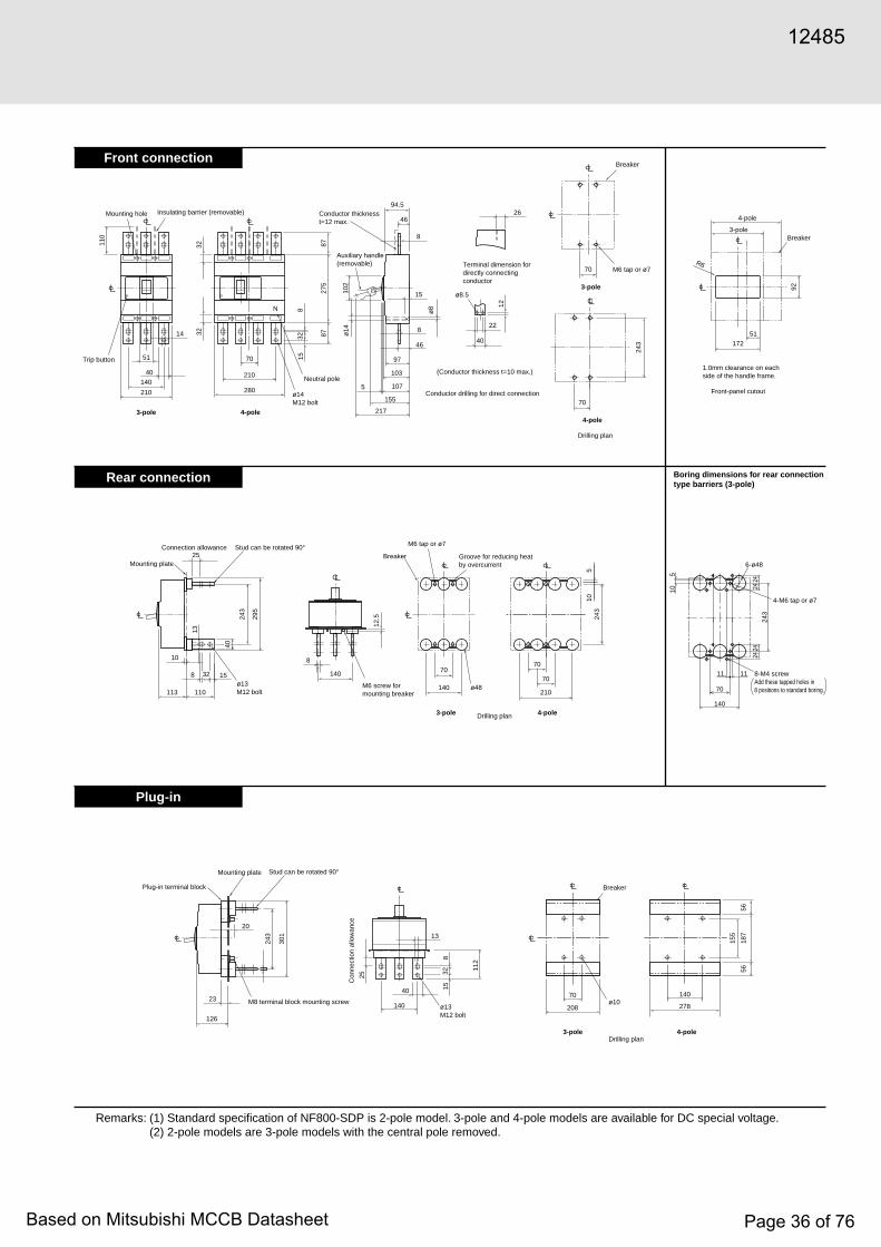
Front connection
Rear connection
Plug-in
Remarks: (1) Standard specification of NF800-SDP is 2-pole model. 3-pole and 4-pole models are available for DC special voltage.(2) 2-pole models are 3-pole models with the central pole removed.
140210
70
N
210 280
110
14
40
51
32
815
32
275
87
97
103
107
87
32
94.5
8
4626
8
4610
2
15
22
40
ø8.5
5
ø14
155
217
12
70
70
243
243
295
243
70
140
40
25
13
8 15
113 110
14032
10
12.5
70
70
210
105
17251
92
R6
8
208
70
278
140
155
5656
18713
40
140
3225
815
112
243
20
301
126
23
Neutral pole
4-pole3-pole
Trip button
Insulating barrier (removable)Mounting hole
ø14M12 bolt
ø8
Conductor thicknesst=12 max.
Conductor drilling for direct connection
(Conductor thickness t=10 max.)
Auxiliary handle(removable) Terminal dimension for
directly connectingconductor
4-pole
3-pole
Breaker
Drilling plan
M6 tap or ø7
4-pole
3-poleBreaker
Front-panel cutout
1.0mm clearance on eachside of the handle frame.
ø48
4-pole3-pole
M6 tap or ø7
Breaker Groove for reducing heatby overcurrent
Drilling plan
M6 screw formounting breaker
ø13M12 bolt
Mounting plate
Stud can be rotated 90°Connection allowance
Mounting plate
Plug-in terminal block
M8 terminal block mounting screw
Stud can be rotated 90°
Con
nect
ion
allo
wan
ce
ø13M12 bolt
3-pole 4-pole
ø10
Drilling plan
Breaker
2424
2424
11 11
140
70
243
6-ø48
510
Boring dimensions for rear connection type barriers (3-pole)
4-M6 tap or ø7
8-M4 screwAdd these tapped holes in 8 positions to standard boring.
12485
Based on Mitsubishi MCCB Datasheet Page 36 of 76

NF800-UEP
■ Operating Characteristics
■ Internal Accessories ■ Current reducing curve
Ambient temperature (°C)
Rat
ed a
mbi
ent
80
70
90
100
110
120
130
0 10 20 30 40 50 60
Con
tinuo
us lo
ad c
urre
nt (%
)
Type name
Rated current In (Amp.)
Number of polesReted insulation voltage Ui (V)
Rat
ed s
hort-
circ
uit
brea
king
cap
acity
(kA)
69035/35
170/170200/200200/200200/200
—
3 4
IEC 60947-2(Icu/Ics)
AC
DC
AC690V500V440V400V230V250V
NF800-UEP
400-800adjustable
LTD operating timeat-125%
1000s(TL=150s set) 670s(TL=100s set) 400s(TL= 60s set) 80s(TL= 12s set)
Pre-alarmpickup current IpIr x(0.70-0.75-0.8-0.85-0.9 ±10%-0.95-1.0)
Pre-alarmoperating time Tp
±20%
(at 200%)
Tp= 2TL
INST pickup current IIx4~x12 ±15%
(Magnification to In)Max. totalbreaking time
STD operating time Ts
STD pickup current Is
12-60-100-150s ±20%(at 200%)
Ir x(2-2.5-3-3.5-4 -5-6-7-8-10) ±15%
0.3 ± 0.06s0.2 ± 0.04s
0.1 ± 0.03s0.06 ± 0.02s
LTD operating time TL
0.01s
0.02s
0.05s
0.1s
0.2s
0.5s
1s
2s
5s
10s
20s30s
1min
2min
4min6min
10min14min20min30min
1h
2h
5h
10h
Ope
ratin
g tim
e
NF800-UEP
Note)Current setting Ir: 400~800A (Adjustable)
Rated Current In: 800A
Instantaneous tripping current (×100% of In)Current (×100% of Ir)
0.6 0.7 1 1.3 2 3 4 5 6 7 10 30 402015
Note: (*1) The designation depends on the number of poles. Refer to the reference page.
■ External Accessories
Accessories
Operating handle
F
S
V
61
63
—
75
76
66
—
66
76
67
F6UPW(*1)
S4SP
—
MI-6SP3 (*1)
HT-4SP
Term
inal c
over Large
Skeleton
Rear
Electrical operation device
TCL-6UP3 (*1)
—
BTC-6SP3 (*1)
HL-4SP
HLS-6UP
(MI)
(HT)
(TC-L)
(TTC)
(BTC)HL
HL-S
Mechanical interlock
Auxiliary handleHandlelock device
Type name Referencepage Accessories Type name Reference
page
(An order for should be placed at the same time as an order of circuit breaker main body.) (4-pole models are provided with auxiliary handle.)■ Standard Attached Parts
Front connection
Rear connection
Mounting screw: 3P:4P:
Insulating barrier:
M6 × 35, M6 × 132 (2pcs each)M6 × 35 (3pcs), M6 × 132 (2pcs)
(3P: 2pcs, 4P: 3pcs)
Mounting screw: 3P:4P:
M6 × 40, M6 × 137 (2pcs each)M6 × 40 (3pcs), M6 × 137 (2pcs)
Type NF800-UEP
SHT or UVTAL AX PAL TILeft-sidemounting
Note: (*1) Right-side mounting is standard of SHT and UVT. Specify separately for left-side mounting.Remark: (1) refer to page 51.
Right-sidemounting
Operating handleLead wiredirection
(*1) (*1)
(*1)(*1)
Characteristics and DimensionsMolded-Case Circuit Breakers
12485
Based on Mitsubishi MCCB Datasheet Page 37 of 76

Front connection
Rear connection
140 210
70
N
210 280
110
14
40
51
815
322
87
194
143
200
204
87
32
143
64
8
810
2
275
15
112
5
ø14
ø7
ø7ø14
252
314
70
70
70
290
27.5
22
40
ø8.5
12
290
290
342
70
140
40
25
13
810
210 110 140
3210
12.5
70
70
210
105
172
51
92
22.5
15
Neutral pole
4-pole3-pole
4-pole
3-pole
Trip button
Insulating barrier (removable)Mounting hole
ø14M12 bolt
Conductor thicknesst=12 max.
Conductor drilling fordirect connection
(Conductor thickness t=10 max.)
Auxiliary handle(removable)
Terminal dimension fordirectly connectingconductor
Breaker
M6 screw or ø7
44 (ON side)123.5 (OFF side)
ø13M12 bolt
Mounting plate
Standard direction of stud is horizontalon power side, and vertical on load side.Otherwise, specify the direction.
Connectionallowance
M6 screw formounting breaker
ø48
4-pole3-pole
M6 tap or ø7
Breaker Groove for reducingheat by overcurrent
R6
4-pole
3-pole Breaker
Front-panel cutout
Drilling plan
Drilling plan
1.0mm clearance on eachside of the handle frame.
2424
2424
11 11
140
70
290
6-ø48
510
Boring dimensions for rear connection type barriers (3-pole)
4-M6 tap or ø7
8-M4 screwAdd these tapped holes in 8 positions to standard boring.
12485
Based on Mitsubishi MCCB Datasheet Page 38 of 76
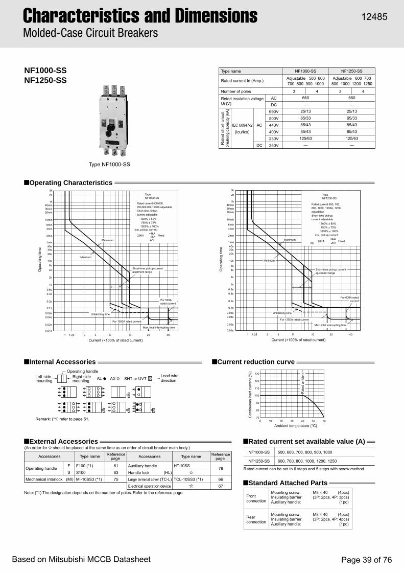
NF1000-SSNF1250-SS
■ Operating Characteristics
■ Internal Accessories ■ Current reduction curve
Ambient temperature (°C)
Rat
ed a
mbi
ent
80
70
90
100
110
120
130
0 10 20 30 40 50 60
Con
tinuo
us lo
ad c
urre
nt (%
)
Type NF1000-SS
Type name
Rated current In (Amp.)
Number of poles
Reted insulation voltage Ui (V)
Rat
ed s
hort-
circ
uit
brea
king
cap
acity
(kA)
660—
25/1365/3385/4385/43
125/63—
660—
25/1365/3385/4385/43
125/63—
3 4
IEC 60947-2(Icu/Ics)
AC
DC
ACDC
690V500V440V400V230V250V
NF1000-SS NF1250-SS
Adjustable 500 600700 800 900 1000
Adjustable 600 700 800 1000 1200 1250
Note: (*1) The designation depends on the number of poles. Refer to the reference page.
■ External Accessories ■ Rated current set available value (A)(An order for should be placed at the same time as an order of circuit breaker main body.)
■ Standard Attached Parts
Front connection
Rated current can be set to 6 steps and 5 steps with screw method.
Rear connection
Mounting screw: M8 × 40 (4pcs)Insulating barrier: (3P: 2pcs, 4P: 3pcs)Auxiliary handle: (1pc)
Mounting screw: M8 × 40 (4pcs)Insulating barrier: (3P: 2pcs, 4P: 4pcs)Auxiliary handle: (1pc)
Accessories
Operating handleF
S61
63
75
76
66
67
F100 (*1)
S100
MI-10SS3 (*1)
Auxiliary handle
Handle lock
Large terminal coverElectrical operation device
HT-10SS
TCL-10SS3 (*1)(MI)(HL)
(TC-L)Mechanical interlock
Type name Referencepage Accessories Type name Reference
page NF1000-SS
NF1250-SS
500, 600, 700, 800, 900, 1000
600, 700, 800, 1000, 1200, 1250
3 4
40s1min
2min
4min6min
10min
20min
Maximum
Short-time pickup currentajustment range
For 1000A rated current
For 500Arated current
Minimum
Unlatching time
30min
20s
10s6s
4s
2s
1s
0.6s0.4s
0.2s
0.1s
0.06s0.04s
0.02s
0.01s
30s
40min1h
2h
3h
Ope
ratin
g tim
e
Current (×100% of rated current)1 1.25 2 3 5 10 4020
Max. total interrupting time
Rated current 500,600,700,800,900,1000A adjustableShort-time pickupcurrent adjustable
500% ± 50% 750% ± 75%1000% ± 100%
inst, pickup current
20KA Fixed
TypeNF1000-SS
AC
+4kA-2kA
40s1min
2min
4min6min
10min
20min
Maximum
Short-time pickup currentajustment range
For 1250A rated current
For 600A ratedcurrent
Minimum
Unlatching time
30min
20s
10s
6s4s
2s
1s
0.6s0.4s
0.2s
0.1s
0.06s0.04s
0.02s
0.01s
30s
40min1h
2h
3h
Ope
ratin
g tim
e
Current (×100% of rated current)1 1.25 2 3 5 10 4020
Max. total interrupting time
Rated current 600, 700,800, 1000, 1200A, 1250adjustableShort-time pickupcurrent adjustable
500% ± 50% 750% ± 75%1000% ± 100%
inst, pickup current
20KA Fixed
TypeNF1250-SS
AC+4kA-2kA
Remark: (*1) refer to page 51.
SHT or UVTAL AXLeft-sidemounting
Right-sidemounting
Operating handleLead wiredirection
Characteristics and DimensionsMolded-Case Circuit Breakers
12485
Based on Mitsubishi MCCB Datasheet Page 39 of 76
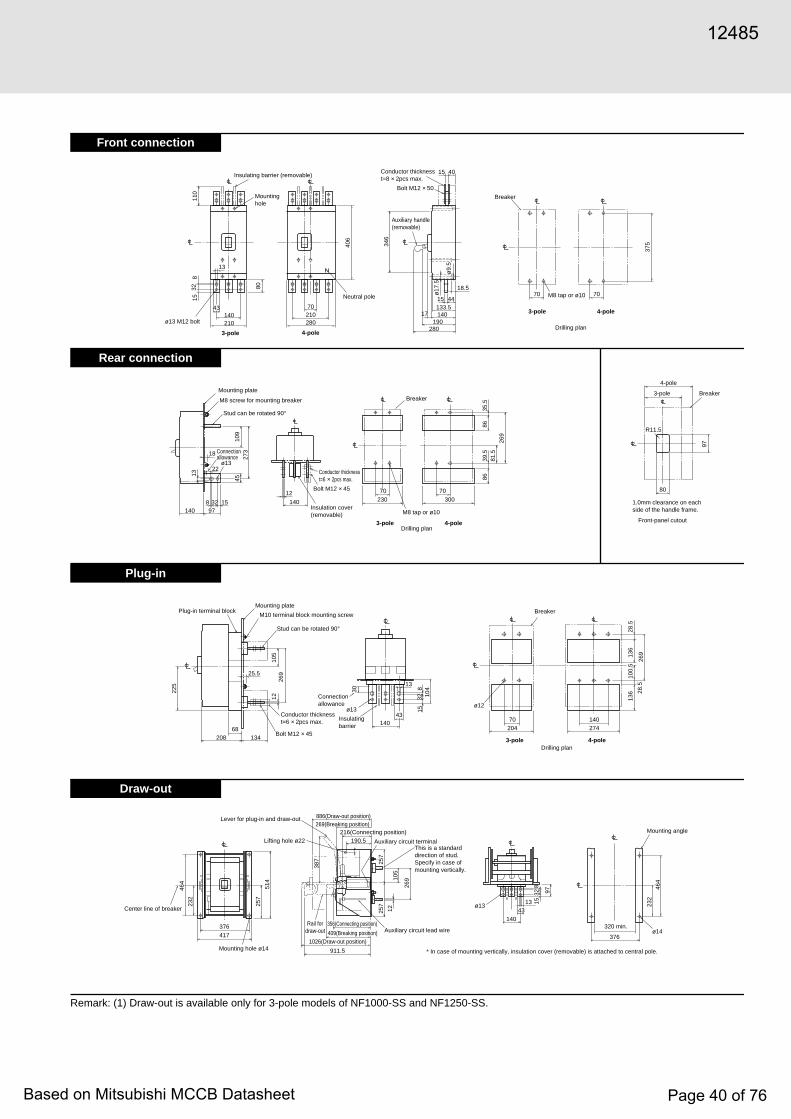
Front connection
Rear connection
Plug-in
Draw-out
Remark: (1) Draw-out is available only for 3-pole models of NF1000-SS and NF1250-SS.
417376
464
232
257
514
387 25
7
97
464
232
257
1210
5
269
911.5
13 1532
8
43
140
376
320 min.
1210
526
9
208 134
140
158
32 104
68
25.5
225
70204
140
136
100.
513
628
.5
269
28.5
274
30
43
13
ø13
140140 230
8686
97
35.5
39.5
81.5
269
300
70 70 80
R11.5
978
13
273
109
15
12
22
18
32
ø13
45
110
832 80
15
13
43140210
21070
280
375
ø17
.5
18.5
280190
14017
15 44
4015
70 70
133.5
406
346
Neutral pole
4-pole3-pole
4-pole3-pole
Insulating barrier (removable)
Mountinghole
ø13 M12 bolt
ø9.
5
Conductor thickness t=8 × 2pcs max.
Bolt M12 × 50
Conductor thicknesst=6 × 2pcs max.
Conductor thicknesst=6 × 2pcs max.
Bolt M12 × 45
Bolt M12 × 45
Insulation cover(removable)
Insulatingbarrier
Lever for plug-in and draw-out
Lifting hole ø22
Mounting hole ø14
886(Draw-out position)
1026(Draw-out position)
Rail fordraw-out
269(Breaking position)216(Connecting position)
Auxiliary circuit terminalThis is a standard direction of stud.Specify in case of mounting vertically.
Auxiliary circuit lead wire
190.5
Center line of breaker
4-pole3-pole
4-pole
3-pole
Breaker
Breaker
BreakerBreaker
M8 tap or ø10
M8 tap or ø10
ø12
ø13
ø14
Mounting angle
* In case of mounting vertically, insulation cover (removable) is attached to central pole.
Drilling plan
Drilling plan
4-pole3-poleDrilling plan
Mounting plate
Connectionallowance
Connectionallowance
M8 screw for mounting breaker
Stud can be rotated 90°
Front-panel cutout
1.0mm clearance on eachside of the handle frame.
Mounting platePlug-in terminal block
M10 terminal block mounting screw
Stud can be rotated 90°
Auxiliary handle(removable)
356(Connecting position)
409(Breaking position)
12485
Based on Mitsubishi MCCB Datasheet Page 40 of 76

Characteristics and DimensionsMolded-Case Circuit Breakers
NF1000-SSDNF1250-SSD
■ Operating Characteristics (page 000)
■ Internal Accessories ■ Ambient Compensating Curve
Type NF1000-SSD
Ambient temperature (°C)
Cur
rent
ratin
g (%
)
1080
90
100
110
120
130
20 30 40 50 605
Rat
ed a
mbi
ent1000A
1200A
Type nameRated current In (Amp.)Number of poles
Rated insulationvoltage Ui (V)
Rated short-circuit breaking capacity (kA)IEC 60947-2
(Icu/Ics)Time constant not larger than
10msec
DC
DC
250V
NF1000-SSD1000
2
250
40/20
NF1250-SSD1250
2
250
40/20
Notes: (*1) The designation depends on the number of poles. Refer to the referenc page.
■ External Accessories ■ Standard Attached Parts(An order for should be placed at the same time as an order of circuit breaker main body.)
Front connection
Rear connection
Mounting screw: M8 × 40 (4pcs)Insulating barrier: (2P: 1pcs, 3P: 2pcs, 4P: 3pcs)Auxiliary handle: (1pc)
Mounting screw: M8 × 40 (4pcs)Insulating cover (3P: 2pcs, 4P: 4pcs)Auxiliary handle: (1pc)
Accessories
Operating handleF
S61
63
75
76
66
67
F100 (*1)
S100
MI-10SS3 (*1)
Auxiliary handle
Handle lock
Large terminal coverElectrical operation device
HT-10SS
TCL-10SS3 (*1)(MI)(HL)
(TC-L)Mechanical interlock
Type name Referencepage Accessories Type name Reference
page
6s4s
2s
1s
3h2h
1h40min
20min
10min
6min4min
2min
1min40s30s20s
10s
0.6s0.4s
0.2s
0.1s
0.06s0.0.4s
0.02s
0.01s
Type NF1000-SSD 1000A DC
Ope
ratin
g tim
e
Current (×100% of rated current)
1 1.25 2 3 4 5 7 10 20 30 5040 70
Maximum
Inst. trip adjustment range(4 steps)
Max. totalinterrupting time
Controlsetting
L023
Hi
Inst. tripcurrent(A)
Minimum
2800 ± 7004200 ± 7005600 ± 7007000 ± 700
Timedelay trip Inst. trip
6s4s
2s
1s
3h2h
1h40min
20min
10min
6min4min
2min
1min40s30s20s
10s
0.6s0.4s
0.2s
0.1s
0.06s0.0.4s
0.02s
0.01s
Type NF1250-SSD 1250A DC
Ope
ratin
g tim
e
Current (×100% of rated current)
1 1.25 2 3 4 5 7 10 20 30 5040 70
Maximum
Inst. trip adjustment range(4 steps)
Max. totalinterrupting time
Controlsetting
L023
Hi
Inst. tripcurrent(A)
Minimum
2800 ± 7004200 ± 7005600 ± 7007000 ± 700
Timedelay trip Inst. trip
SHT or UVTAL AXLeft-sidemounting
Right-sidemounting
Operating handleLead wiredirection
Remark: (1) refer to page 51.
12485
Based on Mitsubishi MCCB Datasheet Page 41 of 76

Front connection
Rear connection
Plug-in
140
140 230
8686
20.5
97
35.5
375
187.
5
300
70 7080
R11.5
97
8
13
233
109
15
12
22
18
18
32
ø13
45
110
832 80
15
13
140210
21070
280
ø9.
5
375
ø17
.5
18.5
280190
14017
15 44
4015
70 70
133.5
406
346
43
208
68 25.5
134
1224
8
Conductor thicknesst=6 × 2pcs max.
Bolt M12 × 45
Mounting platePlug-in terminal block M10 terminal block mounting screw
Stud can be rotated 90˚
140
158
32 10430
43
13
ø13
Insulating barrier
Connection allowance
70
204
140
375
48 318
274
Breaker
ø124-pole3-pole
Drilling plan
4-pole3-pole
Insulating barrier(removable)
Mounting hole
ø13 M12 bolt
Conductor thicknesst=8 × 2pcs max.
Bolt M12 × 50
Auxiliary handle(removable)
4-pole3-pole
Breaker
M8 screw or ø10
Drilling plan
Conductor thicknesst=6 × 2pcs max.
Bolt M12 × 45
Insulation cover(removable)
Mounting plate
Connection allowance
M8 screw for mounting breaker
Stud can be rotated 90˚
4-pole3-pole
Breaker
M8 screw or ø10
Drilling plan
4-pole3-pole Breaker
Front-panel cutout
1.0mm clearance on each sideof the handle frame.
Remarks: (1) Standard specifications of NF1000-SSD and NF1250-SSD are 2-pole models. 3-pole and 4-pole models are for DC special voltage.(2) 2-pole models are 3-pole models with the central pole removed.
Outside dimensions are same as those of NF1000-SS and NF1250-SS.
Outside dimensions are different from those of NF1000-SS and NF1250-SS.
Outside dimensions are different from those of NF1000-SS and NF1250-SS.
12485
Based on Mitsubishi MCCB Datasheet Page 42 of 76

Characteristics and DimensionsMolded-Case Circuit Breakers
NF1250-UR
■ Operating Characteristics
■ Internal Accessories ■ Current reducing curve
Type name
Rated current In (Amp.)
Number of polesReted insulation voltage Ui (V)
Rat
ed s
hort-
circ
uit
brea
king
cap
acity
(kA)
690—
85/42125/65125/65170/85
—
3 4
IEC 60947-2(Icu/Ics)
AC
DC
AC690V500V440V400V230V250V
NF1250-UR
Adjustable600, 700, 800, 1000, 1200, 1250
Notes: (*1) The designation depends on the number of poles. Refer to the reference page.
■ External Accessories
■ Standard Attached Parts
(An order for should be placed at the same time as an order of circuit breaker main body.)
Front connection
Rear connection
Mounting screw: M8 × 45 (4pcs)Insulating barrier: (3P: 2pcs, 4P: 3pcs)Auxiliary handle: (1pc)
Mounting screw: M8 × 45 (4pcs)Insulating cover: (3P: 2pcs, 4P: 4pcs)Auxiliary handle: (1pc)
Accessories
Operating handleF
S61
63
75
76
66
67
F120UR (*1)
S100
MI-12UR3 (*1)
Auxiliary handle
Handle lock
Large terminal coverElectrical operation device
HT-10SS
TCL-12UR3 (*1)(MI)(HL)
(TC-L)Mechanical interlock
Type name Referencepage Accessories Type name Reference
page
■ Rated current set available value (A)
Rated current can be set to 5 steps with screw method.
NF1250-UR 600, 700, 800, 1000, 1250
Type NF1250-UR
Ambient temperature (°C)
Rat
ed a
mbi
ent
80
70
90
100
110
120
130
0 10 20 30 40 50 60
Con
tinuo
us lo
ad c
urre
nt (%
)
3h2h
1h
Current (×100% of rated current)
1 1.25 2 3 4 5 7 10 20 30 6040
40min
20min30min
10min
6min4min
2min
1min40s30s20s
10s
0.6s0.4s
0.2s
0.1s
0.06s0.0.4s
0.02s
0.01s
Ope
ratin
g tim
e
6s4s
2s
1s
Maximum
Minimum
Unlatching timeMaximum total interrupting time
For 1250A rated current
For 600A rated current
Rated current 600,700,800,1000,1200,1250A adjustableShort-time pickupcurrent adjustable
500% ± 50% 750% ± 75%1000% ± 100%
inst. pickup current adjustable
20kA Fixed
TypeNF1250-UR
+4kA-2kA
SHT or UVTAL AXLeft-sidemounting
Right-sidemounting
Operating handleLead wiredirection
Short-time pickup currentadjustment range
Remark: (1) refer to page 51.
12485
Based on Mitsubishi MCCB Datasheet Page 43 of 76

Front connection
Rear connection
Plug-in
375
284194
15
346
51
22.5
1544
144137.5
17
70 70
32
8
8040
6
106
566
13
43
80
15
13
43 70210
310140240
ø17
.5
ø9.
5
ø13
ø17
.5
ø9.
5
28419414417 185
32137.522.5 8
8112
140 260 330 8070 70
8686
39.5
35.5
81.5
269
15
88
22
18
13 4510
9
273
120
97
R11.5
ø9.
5
ø13
ø12
13
30
158
32 104
ø17
.5
352
262
212
137.5 68 134140
204
70
136
100.
513
628
.5
28.5
269
22.5
25.5
225
12
269
105
22.5
17
43
Neutral pole
4-pole3-pole
Insulating barrierInsulating barrier
Mounting hole
Center line of breaker
Mounting hole
Terminal block
Terminal block
ø13 M12 bolt
ø13 M12 bolt
Conductor thicknesst=8 × 2pcs max.
Conductor thicknesst=6 × 2pcs max.
Bolt M12 × 50
Bolt M12 × 45
Auxiliary handle(removable)
Auxiliary handle(removable)
Auxiliary handle(removable)
4-pole3-pole
Breaker
M8 screw or ø10
Drilling plan
4-pole3-pole
Breaker
M8 tap or ø10
Drilling plan
3-pole Drilling plan
Mounting plate
Terminal block
Connectionallowance
M8 screw formounting breaker
Insulation cover(removable)
4-pole3-pole Breaker
Front-panel cutout
1.0mm clearance on each sideof the handle frame.
Conductor thicknesst=6 × 2pcs max.
Bolt M12 × 45
Mounting platePlug-in terminal block
M10 terminal block mounting screw
Stud can be rotated 90˚
Insulating barrier
Connection allowance
Breaker
Standard direction of stud is horizontal on power side, and vertical on load side. Otherwise, specify the direction.
12485
Based on Mitsubishi MCCB Datasheet Page 44 of 76
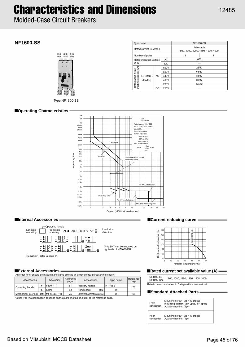
NF1600-SS
■ Operating Characteristics
■ Internal Accessories ■ Current reducing curve
Type name
Rated current In (Amp.)
Number of poles
Reted insulation voltage Ui (V)
Rat
ed s
hort-
circ
uit
brea
king
cap
acity
(kA)
660—
25/1365/3385/4385/43
125/63—
3 4
IEC 60947-2(Icu/Ics)
AC
DC
ACDC
690V500V440V400V230V250V
NF1600-SS
Adjustable800, 1000, 1200, 1400, 1500, 1600
Type NF1600-SS
Rated current can be set to 6 steps with screw method.
NF1600-SSNF1600-PAL 800, 1000, 1200, 1400, 1500, 1600
Notes: (*1) The designation depends on the number of poles. Refer to the reference page.
■ Standard Attached Parts
Front connection
Rear connection
Mounting screw: M8 × 40 (4pcs)Insulating barrier: (3P: 2pcs, 4P: 3pcs)Auxiliary handle: (1pc)
Mounting screw: M8 × 40 (4pcs)Auxiliary handle: (1pc)
■ External Accessories(An order for should be placed at the same time as an order of circuit breaker main body.)
Accessories
Operating handleF
S61
63
75
76
67
F100 (*1)
S100
MI-16SS3 (*1)
Auxiliary handle
Handle lockElectrical operation device
HT-10SS
(MI)(HL)
Mechanical interlock
Type name Referencepage Accessories Type name Reference
page
■ Rated current set available value (A)
40s1min
2min
4min6min
10min
20min
Maximum
Short-time pickup currentadjustment range
For 1600A rated current
For 800A rated current
Minimum
Unlatching time
30min
20s
10s
6s4s
2s
1s
0.6s0.4s
0.2s
0.1s
0.06s0.04s
0.02s
0.01s
30s
40min1h
2h
3h
Ope
ratin
g tim
e
Current (×100% of rated current)1 2 3 4 5 7 10 6030 4020
Max. total interrupting time
Rated current 800, 1000,1200, 1400, 1500, 1600AadjustableShort-time pickupcurrent adjustable
300% ± 30% 450% ± 45% 600% ± 60%
inst, pickup current
20kA Fixed
TypeNF1600-SS
AC
+4kA-2kA
Ambient temperature (°C)
Rat
ed a
mbi
ent
80
70
90
100
110
120
130
0 10 20 30 40 50 60
Con
tinuo
us lo
ad c
urre
nt (%
)SHT or UVTAL AXLeft-sidemounting
Right-sidemounting
Operating handleLead wiredirection
Only SHT can be mounted onright-side of NF1600-PAL.
Remark: (1) refer to page 51.
Characteristics and DimensionsMolded-Case Circuit Breakers
12485
Based on Mitsubishi MCCB Datasheet Page 45 of 76

Front connection
Rear connection
Draw-out
490
416212
466
430
217
ø11
ø17.
5
ø9.
5
210 280
N
203
263364.5
280190
140
133.5
17
20
20 35
70 7080
97
49.5
18.5
304.5
101.5
6038
38
(185
.5)
(185
.5)15
406
130
346
375
115
R11.5
212
273
3660 5418
20
318
106
106
603818
273
269
160
min
.10
0 m
ax.
81.5
109
38
15
15
140 125
70
70
210
140
1515 38
70
109
20
38 38125 15
200140
4-pole3-pole
4-pole3-pole
Insulating barrier(removable)
Insulating barrier(removable)
Mounting hole
Conductor thickness t=6 × W75 max.
Bolt M10 × 65
Auxiliary handle(removable)
Neutral pole 4-pole3-pole
Breaker
Drilling plan
M8 tap or ø10
4-pole3-pole Breaker
Front-panel cutout
1.0mm clearance on each sideof the handle frame.
Stud can be rotated 90˚ Stud can be rotated 90˚
Mounting angle Mounting angle
Mounting angle
ø11BM10 × 50 bolt
ø11M10 × 50 bolt
Connectionallowance
Connectionallowance
Conductor thicknesst=6 × W75 max.
Conductor thicknesst=6 × W75 max.
4-pole3-pole
Breaker
M8 tap or ø10
Drilling plan
ø14
Drilling plan
798 Draw-out position
216 127
28
397
424 Breaking position362 Connecting position
938 Draw-out position
412 Connecting position 101
38 19
20203
150
395
Con
nect
ing
posi
tion
25
3863
.516
827
3
802502 Connecting position
917 Connecting position
Auxiliary handle(removable)
Center line of breaker
Center line of breaker
60 min. 320 min.416
Rotating diameter
Mounting hole ø14
R163
158
217
430
287
550
Rail for draw-out(removable)
Handle for plug-inand draw-out
Liftingholeø30
Auxiliary circuitterminal
ø11M10 bolt
This is a standard direction of stud.Specify in case of mounting vertically.
Remarks: (1) Draw-out is only for 3-pole models of NF1600-SS.
12485
Based on Mitsubishi MCCB Datasheet Page 46 of 76
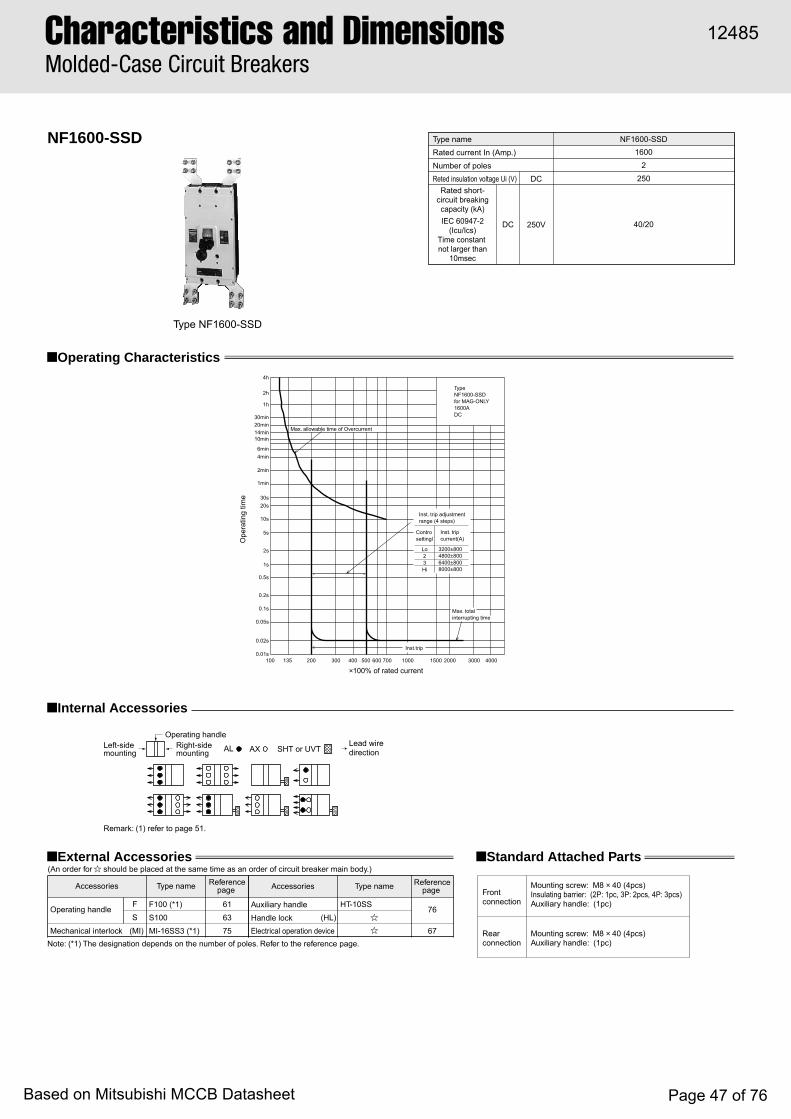
NF1600-SSD
■ Operating Characteristics
Type nameRated current In (Amp.)Number of polesReted insulation voltage Ui (V)
Rated short-circuit breaking capacity (kA)IEC 60947-2
(Icu/Ics)Time constant not larger than
10msec
16002
250
40/20DC
DC
250V
NF1600-SSD
Note: (*1) The designation depends on the number of poles. Refer to the reference page.
■ Standard Attached Parts
Front connection
Rear connection
Mounting screw: M8 × 40 (4pcs)Insulating barrier: (2P: 1pc, 3P: 2pcs, 4P: 3pcs)Auxiliary handle: (1pc)
Mounting screw: M8 × 40 (4pcs)Auxiliary handle: (1pc)
■ External Accessories(An order for should be placed at the same time as an order of circuit breaker main body.)
Accessories
Operating handleF
S61
63
75
76
67
F100 (*1)
S100
MI-16SS3 (*1)
Auxiliary handle
Handle lockElectrical operation device
HT-10SS
(MI)(HL)
Mechanical interlock
Type name Referencepage Accessories Type name Reference
page
■ Internal Accessories
Type NF1600-SSD
SHT or UVTAL AXLeft-sidemounting
Right-sidemounting
Operating handleLead wiredirection
Remark: (1) refer to page 51.
Max. allowable time of Overcurrent
Inst.trip
Inst. trip adjustmentrange (4 steps)
Controsettingl
Inst. tripcurrent(A)
Lo23Hi
3200±8004800±8006400±8008000±800
Max. totalinterrupting time
×100% of rated current100 135 200 300 400 500 600 700 1000 1500 2000 3000 4000
TypeNF1600-SSDfor MAG-ONLY1600ADC
Ope
ratin
g tim
e
0.02s
0.01s
0.05s
0.1s
0.2s
0.5s
1s
2s
5s
10s
20s30s
1min
2min
4min6min
10min14min20min30min
1h
2h
4h
Characteristics and DimensionsMolded-Case Circuit Breakers
12485
Based on Mitsubishi MCCB Datasheet Page 47 of 76
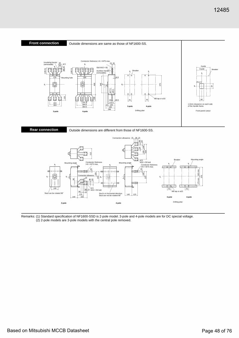
Front connection
Rear connection
ø17
.5
ø9.
5
60ø1138
203263
364.5
18.5
280190
140133.5
20 70 70 80
R11.5
97
17
49.5
304.5101.5
20 35
210 280
(185
.5)
(185
.5)15
3811
5
406
130
346
375
140
140 200125
38 15
15
140
70 70
125
36 38 60
233
212 10
631
823
3
37510
920
106
1838 60
109
20
15
38
15 1538
Insulating barrier(removable)
Mounting hole
4-pole3-pole
Conductor thickness t=6 × W75 max.
Bolt M10 × 65
Auxiliary handle(removable)
4-pole3-pole
Breaker
Drilling plan
M8 tap or ø10
4-pole
3-pole Breaker
Front-panel cutout
1.0mm clearance on each sideof the handle frame.
4-pole3-pole
Stud is in horizontal direction.Stud can not be rotated 90˚
Stud can be rotated 90˚
Mounting angle Mounting angle
ø11M10 × 50 bolt
ø11M10 × 50 bolt
Connection allowance
Connection allowance
Conductor thicknesst=6 × W75 max. Conductor thickness
t=6 × W75 max.
160
min
.17
5 m
in.
Mounting angle
4-pole3-pole
Breaker
M8 tap or ø10
Drilling plan
Outside dimensions are same as those of NF1600-SS.
Outside dimensions are different from those of NF1600-SS.
Remarks: (1) Standard specification of NF1600-SSD is 2-pole model. 3-pole and 4-pole models are for DC special voltage.(2) 2-pole models are 3-pole models with the central pole removed.
12485
Based on Mitsubishi MCCB Datasheet Page 48 of 76
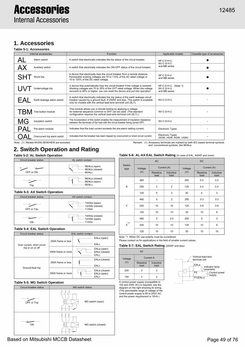
OFF or ON
Trip
OFF or Trip
ON
OFF or Trip
ON
98/ALa (open)96/ALb (closed)95/ALc
98/ALa (closed)96/ALb (open)95/ALc
14/AXa (open)12/AXb (closed)11/AXc
14/AXa (closed)12/AXb (open)11/AXc
Vertical lead-wireterminal unit
Indicator lamp(example)
Control power supply
EALa
P2
P1(EALc)
MG switch (open)
MG switch (closed)
Over current, short circuittrip or on or off
EALa (open)
EALc
EALa (open)EALb (closed)EALc
Ground-fault trip
250A frame or less
400A frame or more
250A frame or less
400A frame or moreEALa (closed)EALb (open)EALc
EALa (closed)
EALc
Note: (1) Models NV250-SEW/HEW are excluded. Remark: (1) Accessory terminals are marked by both IEC-based terminal symbolsand conventional symbols, like 98/ALa.
Note: *1. When DC use polarity must be considered.Please contact us for applications in the field of smaller current values.
A control power supply (compatible to 100 and 200V AC) is required; see the diagram on the right showing its wiring. (The permissible range of voltage of the control power supply is 80 to 242V AC, and the power requirement is 10VA.)
Table 5-6: AL·AX·EAL Switch Rating (In case of EAL, 400AF and more)
Table 5-3: AX Switch Operation
Table 5-4: EAL Switch Operation
Table 5-5: MG Switch Operation
Table 5-7: EAL Switch Rating (250AF and less)
Internal accessories Function Applicable models Cassette-type of accessories
AL Alarm switch A switch that electrically indicates the trip status of the circuit breaker. NF-C·S·H·U,NV-C·S·H·Uand MB seriesAX Auxiliary switch A switch that electrically indicates the ON-OFF status of the circuit breaker.
SHT Shunt tripA device that electrically trips the circuit breaker from a remote distance. Permissible working voltages are 70 to 110% of the AC rated voltage or 70 to 125% of the DC rated voltage.
NF-C·S·H·Uand MB series
NF-C·S·H·U, (Note 1)NV-C·S·H·Uand MB seriesUVT Undervoltage trip
A device that automatically trips the circuit breaker if the voltage is lowered. Working voltages are 70 to 35% of the UVT rated voltage. When the voltage recovers to 85% or higher, you can reset the device and put into operation.
EAL Earth-leakage alarm switchA switch that electrically indicates the trip status of the earth leakage circuit breaker caused by a ground fault. If 250AF and less, This switch is available only for models with the vertical lead-wire terminal unit (SLT).
NV-C·S·H·U –
TBM Test button moduleThis module allows you a remote testing by applying a voltage.An external sequence common to SHT can be used. (The standard configuration requires the vertical lead-wire terminal unit (SLT).)
NV-C·S·H·U –
MG Insulation switch The incorporation of this switch enables the measurement of insulation resistance between the terminals of the load with the circuit breaker being turned OFF. NV-C·S·H·U –
PAL Pre-alarm module
OAL Overcurrent trip alarm switch
Indicates that the load current exceeds the pre-alarm setting current.
Indicates that the breaker has been tripped by overcurrent or short-circuit current.
Electronic Types –
Electronic Types(SGW, HGW, RGW, UGW) –
Circuit breaker status AL switch contact
Circuit breaker status AX switch contact
Circuit breaker status
Circuit breaker status MG switch status
EAL switch contact
Switch type
AC DC
Voltage(V)
Current (A) Voltage(V)
Current (A)
Resistive load
Inductive load
Resistive load
Inductive load
Resistive load
Inductive load
S
V
X
460 – – 250 0.2 0.2
250 3 2 125 0.4 0.4
125 5 3 30 4 3
460
250
125
460
250
125
5
10
10
5
10
10
2
10
10
2.5
10
10
250
125
30
250
125
30
0.3
0.6
10
5
10
10
0.3
0.6
6
3
6
10
AC
Voltage(V)
Current A
200 3 2
100 3 2
1. AccessoriesTable 5-1: Accessories
2. Switch Operation and RatingTable 5-2: AL Switch Operation
●
●
●
●
*1
AccessoriesInternal Accessories
12485
Based on Mitsubishi MCCB Datasheet Page 49 of 76
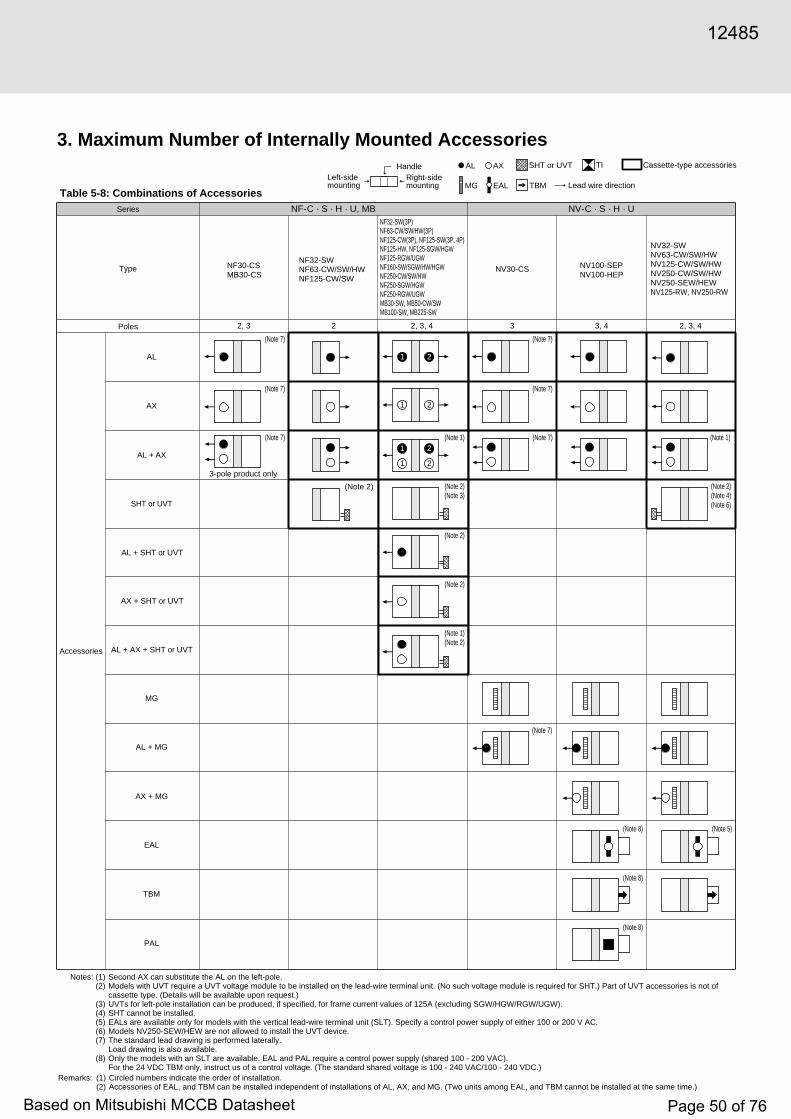
3. Maximum Number of Internally Mounted Accessories
Table 5-8: Combinations of Accessories
Remarks: (1) Circled numbers indicate the order of installation.(2) Accessories of EAL, and TBM can be installed independent of installations of AL, AX, and MG. (Two units among EAL, and TBM cannot be installed at the same time.)
Notes: (1) Second AX can substitute the AL on the left-pole.(2) Models with UVT require a UVT voltage module to be installed on the lead-wire terminal unit. (No such voltage module is required for SHT.) Part of UVT accessories is not of
cassette type. (Details will be available upon request.)(3) UVTs for left-pole installation can be produced, if specified, for frame current values of 125A (excluding SGW/HGW/RGW/UGW).(4) SHT cannot be installed.(5) EALs are available only for models with the vertical lead-wire terminal unit (SLT). Specify a control power supply of either 100 or 200 V AC.(6) Models NV250-SEW/HEW are not allowed to install the UVT device.(7) The standard lead drawing is performed laterally.
Load drawing is also available.(8) Only the models with an SLT are available. EAL and PAL require a control power supply (shared 100 - 200 VAC).
For the 24 VDC TBM only, instruct us of a control voltage. (The standard shared voltage is 100 - 240 VAC/100 - 240 VDC.)
Series NF-C · S · H · U, MB NV-C · S · H · U
Type
Poles
Accessories
AL
AL + SHT or UVT
AX + SHT or UVT
AL + AX + SHT or UVT
AX
AL + AX
SHT or UVT
MG
AL + MG
AX + MG
EAL
TBM
PAL
NF32-SWNF63-CW/SW/HWNF125-CW/SW
NF32-SW(3P)NF63-CW/SW/HW(3P)NF125-CW(3P), NF125-SW(3P, 4P)NF125-HW, NF125-SGW/HGWNF125-RGW/UGWNF160-SW/SGW/HW/HGWNF250-CW/SW/HWNF250-SGW/HGWNF250-RGW/UGWMB30-SW, MB50-CW/SWMB100-SW, MB225-SW
NV32-SWNV63-CW/SW/HWNV125-CW/SW/HWNV250-CW/SW/HWNV250-SEW/HEWNV125-RW, NV250-RW
22, 3 3 3, 42, 3, 4 2, 3, 4
(Note 2) (Note 2)(Note 3)
(Note 2)
(Note 7)
(Note 2)
(Note 1)(Note 2)
(Note 1)
(Note 7)
1 2
1 2
(Note 7)
1 2
1 2
(Note 2)(Note 4)(Note 6)
(Note 1)
(Note 5)
(Note 7)
3-pole product only
(Note 7)
(Note 7)
(Note 7)
(Note 8)
(Note 8)
(Note 8)
NF30-CSMB30-CS
NV30-CS NV100-SEPNV100-HEP
Left-sidemounting
Right-sidemounting
Handle AL AX
MG EAL
SHT or UVT TI Cassette-type accessories
TBM Lead wire direction
12485
Based on Mitsubishi MCCB Datasheet Page 50 of 76

Left-sidemounting
Right-sidemounting
Handle AL AX
MG EAL TBL PAL
SHT or UVT TI Cassette-type accessories
TBM Lead wire direction
AccessoriesInternal Accessories
epyT
S/H/C-FN
U-FN )P3(PEU-004FN PEU-008FN,PEU-036FN,)P4(PEU-004FN
seloP 4,3,2
epythctiwS S V
seirosseccA
LA
✳3
XA
✳3
THSroTVU
✳1✳2
✳1 ✳2✳2
XA+LA
✳3 ✳3
TVUroTHS+LA
✳1✳2✳3✳4
✳1✳2✳3✳4
TVUroTHS+XA
✳1✳2✳3✳4
✳1✳2✳3✳4
TVUroTHS+XA+LA
✳1✳2✳3✳4
✳1
✳2
✳2
✳2✳2✳3✳4
LAP)tuptuotcatnoc(
✳5
PEU/PER/PEH/PES-004FNrofnoitpO
✳5
Option for NF630-SEP/HEP/REP/UEPNF800-CEP/SEP/HEP/REP/UEP
Option for NF630-SEP/HEP/REP/UEPNF800-CEP/SEP/HEP/REP/UEP
IT
✳6
PEU/PER/PEH/PES-004FNrofnoitpO
✳6
.gnitnuomforedroehtswohselcricehtnihtiwrebmunehT✳ .1✳ .)eludomegatlovhcusonseriuqerTHS(eludomegatlovTVUaseriuqergnitnuomTVU.2✳ .yrassecensiTLSredro-laicepsa,XA+LAroXA,LAehtsaelopemasehtotTVUroTHSagnitnuomnehwro,TLSybsecivedgnitnuomelop-tfeleerhtnahteromgnitnuomnehW.3✳ .etarapessieludomegatlovTVUeht,XA+LAro,XA,LAehtsaelopemasehtotTVUagnitnuomnehW.4✳ ).elopthgirs'rekaerbehtotdetnuomebnacseirosseccarehtoon,esacsihtnI(.yrassecensi)V002~001CA(egatlovlortnoC.dradnatssideppiuqe-TLS.5✳ ).elopthgirs'rekaerbehtotdetnuomebnacseirosseccarehtoon,esacsihtnI(.yrassecensi)V002~001CD/V002~001CA(egatlovlortnoC.dradnatssideppiuqe-TLS.6
SHT and UVT are right-pole mounting as standard. Please specify if left-pole mounting is required.
NF400-CP/SPNF400-SEP/HEP/REP
NF630-CP/SPNF630-SEP/HEP/REPNF800-CEP/SDPNF800-SEP/HEP/REP
NF1000-SSNF1250-SSNF1600-SSNF1000-SSDNF1250-SSDNF1600-SSD
NF1250-UR
1 3
2
5
6 4
1
51 3
2 4
2
3
4
1 3
2 4
1
23
1
2
5
3
4
6
12485
Based on Mitsubishi MCCB Datasheet Page 51 of 76

Left-sidemounting
Right-sidemounting
Handle AL AX
MG EAL TBL PAL
SHT or UVT TI Cassette-type accessories
TBM Lead wire direction
epyT S/H/C-VN
seloP 4,3
epythctiwS S
seirosseccA
LA
✳2
XA
✳2
TVUroTHS
✳1 ✳1
XA+LA
✳2 ✳2
TVUroTHS+LA
✳1✳2✳3
✳1✳2✳3
TVUroTHS+XA
✳1✳2✳3
✳1✳2✳3
TVUroTHS+XA+LA
✳1✳2✳3
✳1✳2✳3
GM
GM+LA
✳ .)eludomegatlovhcusonseriuqerTHS(eludomegatlovTVUaseriuqergnitnuomTVU.1✳ .yrassecensiTLSredro-laicepsa,XA+LAroXA,LAehtsaelopemasehtotTVUroTHSagnitnuomnehwro,TLSybsecivedgnitnuomelop-tfeleerhtnahteromgnitnuomnehW.2✳ .etarapessieludomegatlovTVUeht.XA+LAroXA,LAehtsaelopemasehtotTVUagnitnuomnehW.3
The number within the circle shows the order of mounting.
NV400-CP/SPNV400-SEP/HEP/REP
NV630-CP/SPNV630-SEP/HEPNV800-SEP/HEP
12485
Based on Mitsubishi MCCB Datasheet Page 52 of 76

Left-sidemounting
Right-sidemounting
Handle AL AX
MG EAL TBL PAL
SHT or UVT TI
TBM Lead wire direction
AccessoriesInternal Accessories
epyT S/H/C-VN
seloP 4,3
epythctiwS S
seirosseccA
GM+XA
GM+XA+LA
LAE
LBT
MBT
)tuptuotcatnoc(LAP
IT
The number within the circle shows the order of mounting.).ylsuoenatlumisdetnuomebtonnacsMBTrosLBT,sLAEowt,revewoH(.seirosseccaGMdnaTVU,THS,XA,LAforebmunehtfosseldragerdetnuomebnacMBTdna,LBT,LAE.1
.seiresS/C-VN
Option for NV400-SEP/HEP/REP Option for NV630-SEP/HEPNV800-SEP/HEP
Option for NV400-SEP/HEP/REP Option for NV630-SEP/HEPNV800-SEP/HEP
andS/C-FNehtrofegnahcsnoitacificepsdnasnoisnemids’LAPehT.2✳ .1✳ .2
).elopthgirs’rekaerbehtotdetnuomebnacseirosseccarehtoon,esacsihtnI(.yrassecensi)V002-001CA(egatlovlortnoC.dradnatssideppiuqe-TLS).elopthgirs’rekaerbehtotdetnuomebnacseirosseccarehtoon,esacsihtnI(.yrassecensi)V002-001CD/V002-001CA(egatlovlortnoC.dradnatssideppiuqe-TLS
✳1
✳2 ✳ 2
✳ 1
NV400-CP/SPNV400-SEP/HEP/REP
NV630-CP/SPNV630-SEP/HEPNV800-SEP/HEP
12485
Based on Mitsubishi MCCB Datasheet Page 53 of 76
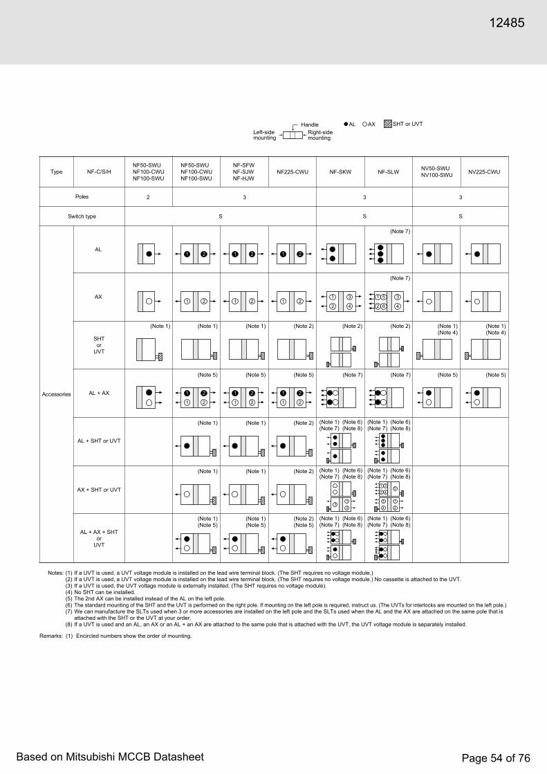
5
Left-sidemounting
Right-sidemounting
Handle AL AX SHT or UVT
epyT NF-C/S/H
seloP
epythctiwS S SS
32 33
seirosseccA
AL
AX
SHTor
UVT
AL + AX
AL + SHT or UVT
AX + SHT or UVT
AL + AX + SHTor
UVT
NF50-SWUNF100-CWUNF100-SWU
NF50-SWUNF100-CWUNF100-SWU
NF-SFWNF-SJWNF-HJW
NF225-CWU NF-SKW NF-SLW NV225-CWUNV50-SWUNV100-SWU
Remarks: (1) Encircled numbers show the order of mounting.
Notes: (1) If a UVT is used, a UVT voltage module is installed on the lead wire terminal block. (The SHT requires no voltage module.)(2) If a UVT is used, a UVT voltage module is installed on the lead wire terminal block. (The SHT requires no voltage module.) No cassette is attached to the UVT.(3) If a UVT is used, the UVT voltage module is externally installed. (The SHT requires no voltage module).(4) No SHT can be installed.(5) The 2nd AX can be installed instead of the AL on the left pole.(6) The standard mounting of the SHT and the UVT is performed on the right pole. If mounting on the left pole is required, instruct us. (The UVTs for interlocks are mounted on the left pole.)(7) We can manufacture the SLTs used when 3 or more accessories are installed on the left pole and the SLTs used when the AL and the AX are attached on the same pole that is
attached with the SHT or the UVT at your order.(8) If a UVT is used and an AL, an AX or an AL + an AX are attached to the same pole that is attached with the UVT, the UVT voltage module is separately installed.
2 4
1 3
(Note 1) (Note 1)
(Note 5)
(Note 1)
(Note 1)
(Note 1)(Note 5)
1 2
1 2
1 2
1 2
1 2
1 2
1 2
1 2
(Note 1)
(Note 5)
(Note 1)
(Note 1)
(Note 1)(Note 5)
1 2
1 2
(Note 2)
(Note 7)
(Note 7)
(Note 2)
(Note 6)(Note 8)
(Note 1)(Note 7)
32
1
(Note 6)(Note 8)
(Note 1)(Note 7)
(Note 6)(Note 8)
(Note 1)(Note 7)
(Note 5) (Note 7) (Note 5)
(Note 2)
(Note 2)
(Note 2)(Note 5)
(Note 1)(Note 4)
1 2
1 2
2 4
1
6
5 3
(Note 2)
(Note 6)(Note 8)
(Note 1)(Note 7)
2
1
4
35
4
3
2
1
(Note 6)(Note 8)
(Note 1)(Note 7)
(Note 6)(Note 8)
(Note 1)(Note 7)
(Note 7) (Note 5)
(Note 1)(Note 4)
12485
Based on Mitsubishi MCCB Datasheet Page 54 of 76
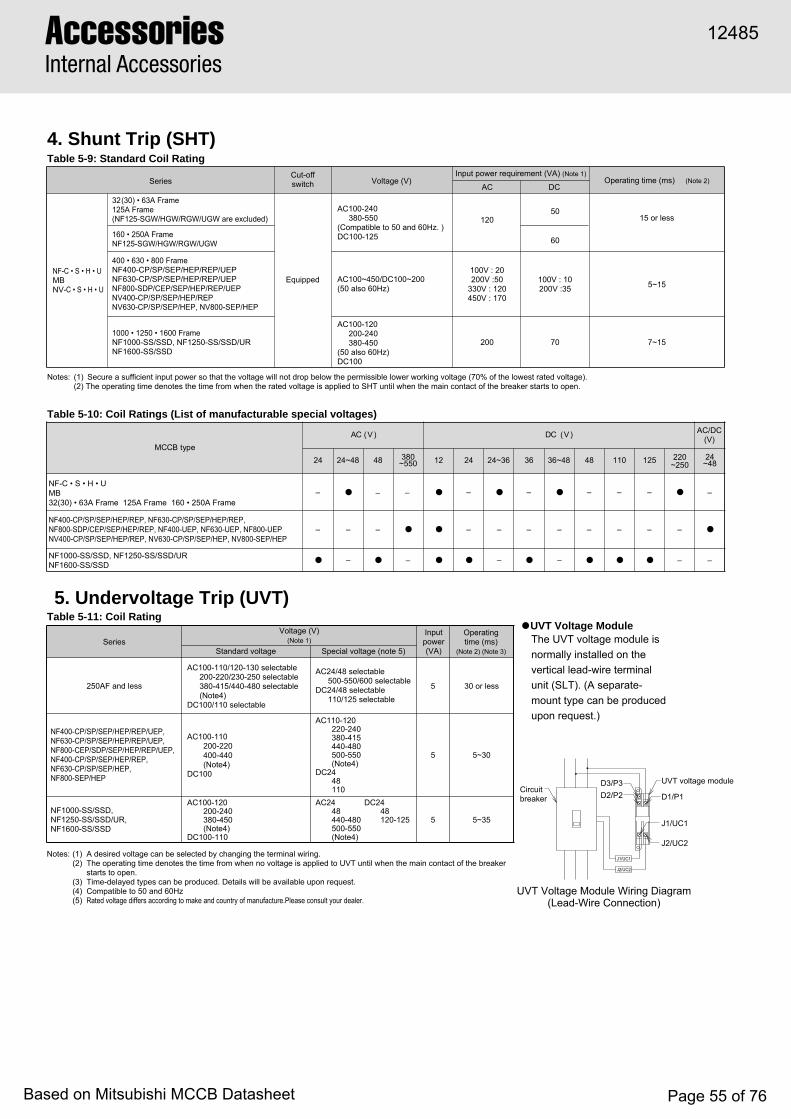
UVT Voltage Module Wiring Diagram(Lead-Wire Connection)
J1/UC1
J2/UC2
Circuitbreaker
UVT voltage module
D1/P1
J1/UC1
J2/UC2
D3/P3D2/P2
4. Shunt Trip (SHT)Table 5-9: Standard Coil Rating
5. Undervoltage Trip (UVT)● UVT Voltage Module
Notes: (1) Secure a sufficient input power so that the voltage will not drop below the permissible lower working voltage (70% of the lowest rated voltage).(2) The operating time denotes the time from when the rated voltage is applied to SHT until when the main contact of the breaker starts to open.
The UVT voltage module is normally installed on the vertical lead-wire terminal unit (SLT). (A separate-mount type can be produced upon request.)
Notes: (1) A desired voltage can be selected by changing the terminal wiring.(2) The operating time denotes the time from when no voltage is applied to UVT until when the main contact of the breaker
starts to open.(3) Time-delayed types can be produced. Details will be available upon request.(4) Compatible to 50 and 60Hz(5) Rated voltage differs according to make and country of manufacture.Please consult your dealer.
SeriesCut-offswitch Voltage (V)
Input power requirement (VA) (Note 1)Operating time (ms) (Note 2)
AC DC
NF-C • S • H • UMBNV-C • S • H • U
32(30) • 63A Frame125A Frame(NF125-SGW/HGW/RGW/UGW are excluded)
160 • 250A FrameNF125-SGW/HGW/RGW/UGW
400 • 630 • 800 FrameNF400-CP/SP/SEP/HEP/REP/UEPNF630-CP/SP/SEP/HEP/REP/UEPNF800-SDP/CEP/SEP/HEP/REP/UEPNV400-CP/SP/SEP/HEP/REPNV630-CP/SP/SEP/HEP, NV800-SEP/HEP
1000 • 1250 • 1600 FrameNF1000-SS/SSD, NF1250-SS/SSD/URNF1600-SS/SSD
Equipped
AC100-240380-550
(Compatible to 50 and 60Hz. )DC100-125
AC100~450/DC100~200(50 also 60Hz)
AC100-120200-240380-450
(50 also 60Hz)DC100
15 or less120
100V : 20200V :50
330V : 120450V : 170
100V : 10200V :35
200 70 7~15
5~15
60
50
Table 5-11: Coil Rating
SeriesVoltage (V)
(Note 1)Input power(VA)
Operatingtime (ms)
(Note 2) (Note 3)
250AF and less
NF400-CP/SP/SEP/HEP/REP/UEP,NF630-CP/SP/SEP/HEP/REP/UEP,NF800-CEP/SDP/SEP/HEP/REP/UEP,NF400-CP/SP/SEP/HEP/REP,NF630-CP/SP/SEP/HEP,NF800-SEP/HEP
NF1000-SS/SSD,NF1250-SS/SSD/UR,NF1600-SS/SSD
AC100-110/120-130 selectable200-220/230-250 selectable380-415/440-480 selectable(Note4)
DC100/110 selectable
AC24/48 selectable500-550/600 selectable
DC24/48 selectable110/125 selectable
AC100-110200-220400-440(Note4)
DC100
AC100-120200-240380-450(Note4)
DC100-110
AC110-120220-240380-415440-480500-550(Note4)
DC2448110
AC2448440-480500-550(Note4)
DC2448120-125
5 30 or less
5 5~30
5 5~35
Standard voltage Special voltage (note 5)
epytBCCMCA )V( CD )V( AC/DC
(V)
42 84 083055~ 21 42 63 84 011 521 220
~2504284~
● –
● ● – ● ● ● ● ● ● –
– – ● ● – – – – – –
–
●NF400-CP/SP/SEP/HEP/REP, NF630-CP/SP/SEP/HEP/REP,NF800-SDP/CEP/SEP/HEP/REP, NF400-UEP, NF630-UEP, NF800-UEPNV400-CP/SP/SEP/HEP/REP, NV630-CP/SP/SEP/HEP, NV800-SEP/HEP
NF-C • S • H • UMB32(30) • 63A Frame 125A Frame 160 • 250A Frame
NF1000-SS/SSD, NF1250-SS/SSD/URNF1600-SS/SSD
–
24~48
–
–
● –
Table 5-10: Coil Ratings (List of manufacturable special voltages)
–
24~36
–
36~48
– – – ●
–
–
●
–
–
●–
AccessoriesInternal Accessories
12485
Based on Mitsubishi MCCB Datasheet Page 55 of 76

5
18
TBM2TBM1
7
12.5
92 (
Ter
min
al
c
over
)
(10.
5)10.5
6. Test Button Module (TBM)
7. Lead-wire Specifications
Table 5-12
● The effect of pressing the test button on the breaker main body is produced while the input control voltage is applied. (Apply the voltage for more than two seconds for the breaker main body of time-delayed NV models.)
● The model with the vertical lead-wire terminal unit (SLT) is standard.
8. Internal Terminal Type (INT)● This unit is an internal accessory that is provided with terminal screws for lead-wire connection.
● Lead wires are normally extended laterally.● Grooves are provided standardly on the side face of the breaker,
allowing the extension of the lead wires along them. (Note 1)
Note: (1) The models of NF125-SGW/HGW/RGW/UGW, NF160-SGW/HGW,NF250-SGW/HGW/RGW/UGW, 400Aframe and more are excluded.
Remark: (1) Available for the models of NF125-SGW/HGW/RGW/UGW,NF160-SGW/HGW, NF250-SGW/HGW/RGW/UGW.
Table 5-13
Series NV-C • S • H • U
Input rated control voltage (V)
Compatible toAC100-240/
DC100-240(DC24) (Note 1)
Input control power (VA)
1VA or less
Type Size Length Marking Ring-mark example
Heat-resistant wire
A ring-mark marked by the terminal symbol is attached to each lead-wire.
0.5mm2
(Note 1)
450mm98/ALa , 96/ALb , 95/ALc
C1/S1 , C2/S2
Note: (1) The specifications of 100-240VAC/100-240V DC are standard unless otherwise specified. The specifications of 24 V DC areavailable if requested.
Note: (1) The length is 400 mm for the model of four-pole, right-pole installation.
12485
Based on Mitsubishi MCCB Datasheet Page 56 of 76

Applicable models A B C D E4
7
77725257
41
62.5
138
4.5
17.5
27.51929253537
79.588.5173
119.5135.5
44.5
54
5454545454545454525454
86.5
86.5
86.586.586.586.586.586.586.586.586.586.586.5
4.5
17.5
27.51929253537
79.588.5173
119.5135.5
18
712.5
D 2510
.510
.5 FE
52G
Terminal cover(Skeleton)
86.5
B
A C
38.5
26.5
14.5 8
13.5
M3.5 terminal screw
Remarks: (1) Terminal screw tightening torque M3.5 ··· 0.9~1.2N·m(2) Lead-wire terminal block for TBL is attached to right-side.
Applicable models A B C D ENV30-CSNV32-SW, NV63-CW/SW/HWNV50-SWUNV125-CW/SW/HWNV100-SWUNV100-SEP/HEPNV250-CW/SW/HW, NV250-SEW/HEW, NV225-CWUNV125-RWNV250-RWNV400-CP/SP/HP/HEP/REPNV630-CP/SP/SEP/HEP, NV800-SEP/HEP
4777777774141
4.517.527.51929303780
11279.588.5
44.554545454545454545454
86.586.586.586.586.586.586.586.586.586.586.5
47777
2.52.57
2.526.526.5
F4.5
21.531.51929303780
11279.588.5
G86.59292
86.586.59292
86.5929292
Terminal cover(Skeleton)
M3.5 terminal screw
A 75
B
115
1111 11
419
25
17
7
Applicable models ANFB NV
B
NV400-CP/SP/SEPNV400-HEP/REP
NV630-CP/SP/SEP/HEPNV800-SEP/HEP
20
117
20
117
60
100
69
116
–
–
NF30-CS, MB30-CSNF32-SW, NF63-CW/SW/HWMB30-SW, MB50-CW/SWNF50-SWUNF125-CW/SW/HWNF100-CWU, NF100-SWUNF125-HGW, NF225-HGWNF-SFW,NF-SJW, NF-HJWNF250-CW/SW/HW, NF225-CWU, NF160-SW/HWNF400-CP/SP/SEP/HEP/REP, NF-SKWNF630-CP/SP/SEP/HEP/REP, NF800-CEP/SDP/SEP/HEP/REP, NF-SLWNF1000-SS/SSD, NF1250-SS/SSD, NF1600-SS/SS (Note1)
NF400-UEP(3P)NF400-UEP(4P), NF630-UEP, NF800-UEP
NF400-CP/SP/SEPNF400-HEP/REP, NF-SKWNF400-UEP(3P)NF630-CP/SP/SEPNF630-HEP/REPNF800-CEP/SDP/SEPNF800-HEP/REP, NF-SLWNF400-UEP(4P), NF630-UEP, NF800-UEP
Table 5-14: Summary of Dimensions
Table 5-15: Summary of Dimensions
Table 5-16
Note: (1) SLT can not be mounted when more than 3 pieces of accessories are mounted on one side in larger frame than 1000A frame.Remark: (1) Terminal screw tightening torque M3.5 ··· 0.9~1.2N·m
Remark: (1) Terminal screw tightening torque
■14 Terminals SLT
■NV
■NFB
SLT when three and more than three pieces of internal accessories are mounted on left-side.
9. Vertical Lead-wire Terminal Block (SLT)● The circuit beaker can be mounted, being closely fitted to the unit.● Terminal screws are arranged in a zigzag pattern, and screws can be tightened further after wiring.● A terminal cover is provided standardly.● This unit supports the models of front connection, rear connection, and plug-in type (excluding PLT).
18
712.5
D 2510
.510
.5 E
Terminal cover(Skeleton)
86.5
B
A C
38.5
26.5
14.5 8
13.5
M3.5 terminal screw
AccessoriesInternal Accessories
12485
Based on Mitsubishi MCCB Datasheet Page 57 of 76
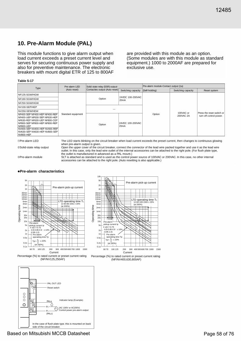
5
epyTDELmrala-erP)teserotuA(
-tuptuo)RSS(yaleretatsdiloS)teserotuA(tuptuoseitcatnoC
)a1(tuptuotcatnoC-eludommrala-erP
yticapacgnihctiwS )gnidloh-fleS( yticapacgnihctiwS metsysteseR
NF125-SGW/HGW
tnempiuqedradnatS
Option
Option
CAV002-001CDV42Am02
noitpO roCAV001A2CAV002
rohctiwsteserehtsserP.rewoplortnocffonrut
NF160-SGW/HGW
NF250-SGW/HGW
NV100-SEP/HEP—
NV250-SEW/HEWPER-004FNPEH-004FNPES-004FNPEH-036FNPES-036FNPEU-004FNPEC-008FNPEU-036FNPER-036FNPER-008FNPEH-008FNPES-008FN
PEU-008FNCAV002-001CDV42
Am02PER-004VNPEH-004VNPES-004VNPES-008VNPEH-036VNPES-036VN
PEH-008VN
Table 5-17
Pre-alarm LED The LED starts blinking on the circuit breaker when load current exceeds the preset current, then changes to continuous glowing when pre-alarm output is given.
Solid-state relay output Open the upper cover of the circuit breaker, connect the connector of the lead wire packed together and use it as the lead wire outlet. In this case, only the lead wire outlet of the internal accessories can be attached to the right pole. (For flush plate type, the outlet is manufactured in advanced as a PAL mount.)
Pre-alarm module SLT is attached as standard and is used as the control power source of 100VAC or 200VAC. In this case, no other internal accessories can be attached to the right pole. (Auto resetting is also applicable.)
PAL OUT LED
Reset switch
Indicator lamp (Example)
(AC 100V or AC200V)Control power pre-alarm output
PALa
P2
P1
(PALc)
In the case of flush plate type. this is mounted on back side of the circuit breaker.
RISET
10. Pre-Alarm Module (PAL)
This module functions to give alarm output whenload current exceeds a preset current level andserves for securing continuous power supply andalso for preventive maintenance. The electronicbreakers with mount digital ETR of 125 to 800AF
•Pre-alarm characteristics
are provided with this module as an option.(Some modules are with this module as standardequipment.) 1000 to 2000AF are prepared forexclusive use.
Pre-alarm pick-up current
LTD operating time TL12-60-80-100s ± 20%(at 200%)
60 70 100 125 200 300 400 500 600 700 1000 15000.1s
0.2s
0.5s
1s
2s
5s
10s
20s30s
1min
2min
4min6min
10min14min20min30min
1h
2h
5h
Pre-alarmpickup current IpIr x(0.7-0.75 -0.8-0.85-0.9 ± 10% -0.95-1.0)
Pre-alarmoperatiing time Tp
± 20%
(at 200%)
Tp=2TL
Current
Ope
ratin
g tim
e
Percentage (%) to rated current or preset current rating(NF/NV125,250AF)
Percentage (%) to rated current or preset current rating(NF/NV400,630,800AF)
Pre-alarm pick-up current
LTD operating time TL12-60-100-150s ± 20%(at 200%)
60 70 100 125 200 300 400 500 600 700 1000 15000.1s
0.2s
0.5s
1s
2s
5s
10s
20s30s
1min
2min
4min6min
10min14min20min30min
1h
2h
5h
10h
Pre-alarmpickup current IpIr x(0.7-0.75 -0.8-0.85-0.9 ± 10% -0.95-1.0)
Pre-alarmoperatiing time Tp
± 20%
(at 200%)
Tp=2TL
Current
Ope
ratin
g tim
e
12485
Based on Mitsubishi MCCB Datasheet Page 58 of 76
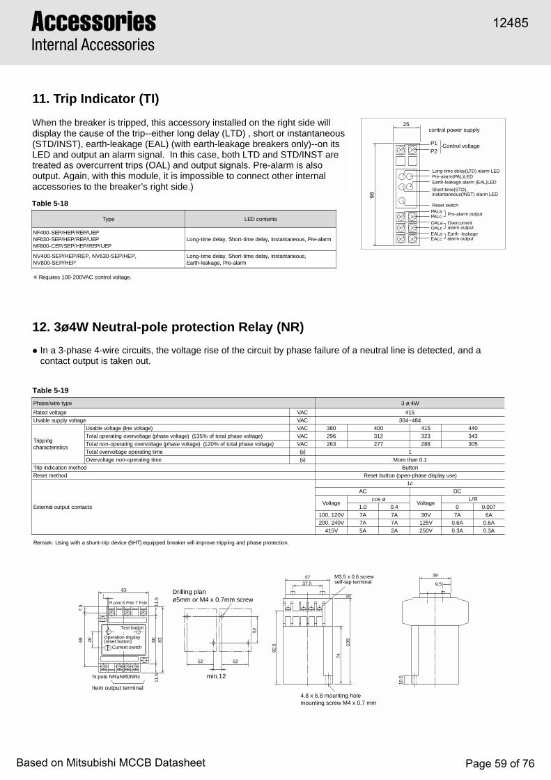
11. Trip Indicator (TI)
When the breaker is tripped, this accessory installed on the right side willdisplay the cause of the trip--either long delay (LTD) , short or instantaneous(STD/INST), earth-leakage (EAL) (with earth-leakage breakers only)--on itsLED and output an alarm signal. In this case, both LTD and STD/INST aretreated as overcurrent trips (OAL) and output signals. Pre-alarm is alsooutput. Again, with this module, it is impossible to connect other internalaccessories to the breaker’s right side.)
control power supply
Long-time delay(LTD) alarm LEDPre-alarm(PAL)LEDEarth-leakage alarm (EAL)LED
Reset switch
Pre-alarm output
Overcurrentalarm outputEarth -leakagealarm output
PALaPALcOALaOALcEALaEALc
Short-time(STD),instantaneous(INST) alarm LED
Control voltageP1
25
98
P2
epyT stnetnocDEL
PEU/PER/PEH/PES-004FNPEU/PER/PEH/PES-036FN
PEU/PER/PEH/PES/PEC-008FNmrala-erP,suoenatnatsnI,yaledemit-trohS,yaledemit-gnoL
,suoenatnatsnI,yaledemit-trohS,yaledemit-gnoLmrala-erP,egakael-htraE
✳ .egatlovlortnocCAV002-001seriuqeR
NV400-SEP/HEP/REP, NV630-SEP/HEP,NV800-SEP/HEP
Table 5-18
epyteriw/esahP W4ø3
egatlovdetaR CAV 514egatlovylppuselbasU CAV 484~403
gnippirTscitsiretcarahc
)egatlovenil(egatlovelbasU CAV 083 004 514 044)egatlovesahplatotfo%531()egatlovesahp(egatlovrevognitarepolatoT CAV 692 213 323 343
)egatlovesahplatotfo%021()egatlovesahp(egatlovrevognitarepo-nonlatoT CAV 362 772 882 503emitgnitarepoegatlovrevolatoT )s( 1emitgnitarepo-nonegatlovrevO )s( 1.0nahteroM
dohtemnoitacidnipirT nottuBdohtemteseR )esuyalpsidesahp-nepo(nottubteseR
stcatnoctuptuolanretxE
c1CA CD
egatloVøsoc
egatloVR/L
0.1 4.0 0 700.0V021,001 A7 A7 V03 A7 A6V042,002 A7 A7 V521 A6.0 A6.0
V514 A5 A2 V052 A3.0 A3.0
.noitcetorpesahpdnagnippirtevorpmilliwrekaerbdeppiuqe)THS(ecivedpirt-tnuhsahtiwgnisU:krameR
Table 5-19
• In a 3-phase 4-wire circuits, the voltage rise of the circuit by phase failure of a neutral line is detected, and acontact output is taken out.
52 52
52
min.12
Drilling planø5mm or M4 x 0.7mm screwR pole S Pole T Pole
687.
5
20 6011
.511
.583
63
Test button
Operation display(reset button)
Current switch
N pole NRaNRbNRc
Item output terminal4.8 x 6.8 mounting holemounting screw M4 x 0.7 mm
M3.5 x 0.6 screwself-tap terminal
5737.5
92.5
74
610
9
10.5
39
9.5
12. 3ø4W Neutral-pole protection Relay (NR)
AccessoriesInternal Accessories
12485
Based on Mitsubishi MCCB Datasheet Page 59 of 76
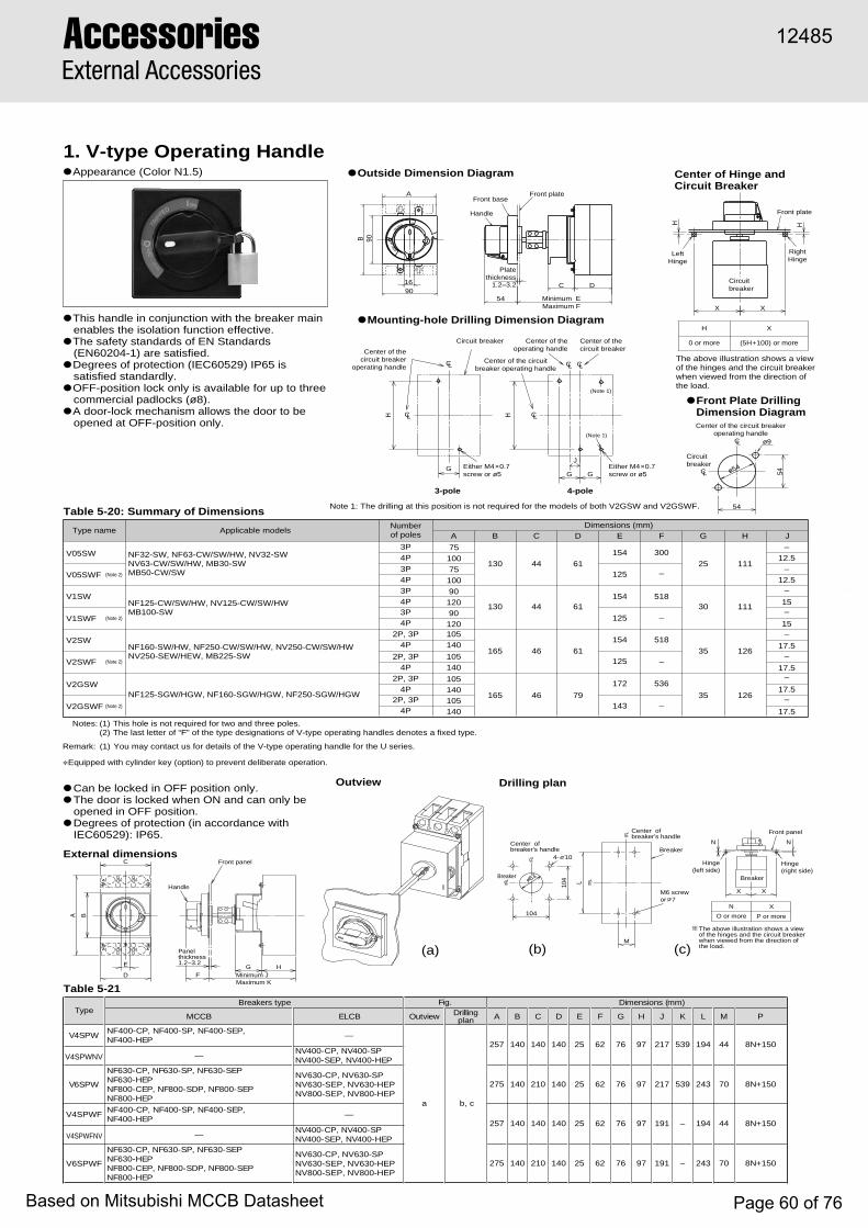
5
AccessoriesExternal Accessories
● Outside Dimension Diagram Center of Hinge andCircuit Breaker
● Mounting-hole Drilling Dimension Diagram
The above illustration shows a view of the hinges and the circuit breaker when viewed from the direction of the load.
H X
0 or more (5H+100) or more
● Front Plate DrillingDimension DiagramCenter of the circuit breaker
operating handle
Circuitbreaker
54
54ø54
ø9
16
90B
90
A
N
OFF
RESE
T
OPED
TR
IP
XX
HH
LeftHinge
RightHinge
Front plate
Front plate
Platethickness
1.2–3.2
Handle
Front base
54
C D
Minimum EMaximum F
Front panel
E
D F Minimum JMaximum K
G H
C
A B
Panelthickness1.2~3.2
Handle
The above illustration shows a view of the hinges and the circuit breaker when viewed from the direction of the load.
Breaker
Breaker
N X
O or more P or more
Hinge(left side)
Hinge(right side)
X X
4- 10
M6 screwor 7
Center ofbreaker's handle
Center ofbreaker's handle
Front panel
104
104
Breaker
L
M
63
Note 1: The drilling at this position is not required for the models of both V2GSW and V2GSWF.
Circuitbreaker
Center of thecircuit breaker
operating handle
Center of theoperating handle
Center of thecircuit breaker
Center of the circuitbreaker operating handle
3-pole 4-pole
Circuit breaker
H H
GG G
JEither M4×0.7screw or ø5
Either M4×0.7screw or ø5
CL
CL CL
CL CL
CL
CL
(Note 1)
(Note 1)
Table 5-21
(b)(a)
Outview
External dimensions
Drilling plan
(c)
1. V-type Operating Handle● Appearance (Color N1.5)
Table 5-20: Summary of Dimensions
● This handle in conjunction with the breaker main enables the isolation function effective.
● The safety standards of EN Standards (EN60204-1) are satisfied.
● Degrees of protection (IEC60529) IP65 is satisfied standardly.
● OFF-position lock only is available for up to three commercial padlocks (ø8).
● A door-lock mechanism allows the door to be opened at OFF-position only.
● Can be locked in OFF position only.● The door is locked when ON and can only be
opened in OFF position.● Degrees of protection (in accordance with
IEC60529): IP65.
Type name Applicable modelsNumberof poles
Dimensions (mm)A B C D E F G H J
NF32-SW, NF63-CW/SW/HW, NV32-SWNV63-CW/SW/HW, MB30-SWMB50-CW/SW
130 44 61300
25 111
V1SWNF125-CW/SW/HW, NV125-CW/SW/HWMB100-SW
9012090120
130 44 61154 518
30 111(Note 2)V1SWF
(Note 2)V05SWF
V05SW
125
154
125
–
–
V2SWNF160-SW/HW, NF250-CW/SW/HW, NV250-CW/SW/HWNV250-SEW/HEW, MB225-SW
165 46 61
154 518
35 126(Note 2)V2SWF 125 –
V2GSWNF125-SGW/HGW, NF160-SGW/HGW, NF250-SGW/HGW
105140105140
165 46 79
172 536
35 126(Note 2)V2GSWF 143 –
Notes: (1) This hole is not required for two and three poles.(2) The last letter of “F” of the type designations of V-type operating handles denotes a fixed type.
Remark: (1) You may contact us for details of the V-type operating handle for the U series.
3P
3P
2P, 3P
2P, 3P
105
105
140
1402P, 3P
2P, 3P
–
15
–
–12.5
–12.5
15
–
17.5
–
17.5
–
17.5
–
17.5
4P
4P
3P
3P
4P
4P
4P
4P
4P
4P
✽ Equipped with cylinder key (option) to prevent deliberate operation.
epyTepytsrekaerB .giF )mm(snoisnemiD
BCCM BCLE weivtuO gnillirDnalp A B C D E F G H J K L M P
PWS4V,PES-004FN,PS-004FN,PC-004FN
PEH-004FN—
a c,b
752 041 041 041 52 26 67 79 712 935 491 44 051+N8
V4SPWNV —PS-004VN,PC-004VN
PEH-004VN,PES-004VN
PWS6V
V4SPWF
V4SPWFNV
V6SPWF
PES-036FN,PS-036FN,PC-036FNPEH-036FN
PES-008FN,PDS-008FN,PEC-008FNPEH-008FN
572 041 012 041 52 26 67 79 712 935 342 07
752 041 041 041 52 26 67 79 191 – 491 44
572 041 012 041 52 26 67 79 191 – 342 07
051+N8
051+N8
051+N8
NV630-CP, NV630-SPNV630-SEP, NV630-HEPNV800-SEP, NV800-HEP
,PES-004FN,PS-004FN,PC-004FNPEH-004FN
—
—PS-004VN,PC-004VN
PEH-004VN,PES-004VNPES-036FN,PS-036FN,PC-036FN
PEH-036FNPES-008FN,PDS-008FN,PEC-008FN
PEH-008FN
NV630-CP, NV630-SPNV630-SEP, NV630-HEPNV800-SEP, NV800-HEP
N N
7510075100
12485
Based on Mitsubishi MCCB Datasheet Page 60 of 76
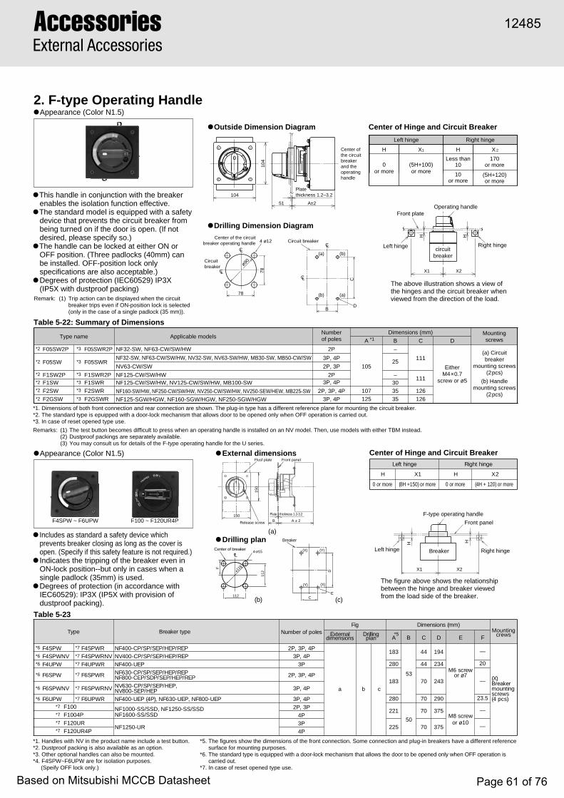
AccessoriesExternal Accessories
Left hinge
F-type operating handle
Front panel
Right hinge
H
Breaker
● Outside Dimension Diagram
● Drilling Dimension Diagram
The above illustration shows a view of the hinges and the circuit breaker when viewed from the direction of the load.
The figure above shows the relationship between the hinge and breaker viewed from the load side of the breaker.
Center of the circuitbreaker operating handle 4 ø12
78
78ø90
CL
CL
Circuit breaker
Circuitbreaker
(a) (b)
(b)
C
BD
CL
CL
(a)
X1 X2
H H
Left hinge Right hinge
Operating handleFront plate
Center ofthe circuitbreakerand theoperatinghandle
51
Platethickness 1.2–3.2
A±2
104
104
ESAE
LER
OPEN
SE ERT
OFF
TRIPPED
ON
circuitbreaker
H
X1 X2
(c)
Breaker
D
E
(X)
(X)
(Y)
(Y)
C(b)
112
112
118
4- 15
F
Center of breaker
2. F-type Operating Handle● Appearance (Color N1.5)
Center of Hinge and Circuit Breaker
● Appearance (Color N1.5)
● This handle in conjunction with the breaker enables the isolation function effective.
● The standard model is equipped with a safety device that prevents the circuit breaker from being turned on if the door is open. (If not desired, please specify so.)
● The handle can be locked at either ON or OFF position. (Three padlocks (40mm) can be installed. OFF-position lock only specifications are also acceptable.)
● Degrees of protection (IEC60529) IP3X(IP5X with dustproof packing)
● Includes as standard a safety device which prevents breaker closing as long as the cover is open. (Specify if this safety feature is not required.)
● Indicates the tripping of the breaker even in ON-lock position--but only in cases when a single padlock (35mm) is used.
● Degrees of protection (in accordance with IEC60529): IP3X (IP5X with provision of dustproof packing).
Left hinge Right hinge
H X1 H X 2
0or more
(5H+100)or more
Less than 10
10or more
170or more
(5H+120)or more
Table 5-22: Summary of Dimensions
● Drilling plan
Type name Applicable modelsNumberof poles
Dimensions (mm) Mounting screwsA B C D
F05SW2P NF32-SW, NF63-CW/SW/HW 2P
105
–
111
111
EitherM4×0.7
screw or ø5
(a) Circuit breaker
mounting screws(2pcs)
(b) Handle mounting screws
(2pcs)
F05SW3P, 4P
25NV63-CW/SW 2P, 3P
F1SW2P NF125-CW/SW/HW 2P –F1SW 3P, 4P 30
F2SW 2P, 3P, 4P 107 35 126
F2GSW
F05SWR2P
F05SWR
F1SWR2PF1SWR
F2SWRF2GSWR 3P, 4P 125 35 126
Remark: (1) Trip action can be displayed when the circuitbreaker trips even if ON-position lock is selected(only in the case of a single padlock (35 mm)).
Remarks: (1) The test button becomes difficult to press when an operating handle is installed on an NV model. Then, use models with either TBM instead. (2) Dustproof packings are separately available.(3) You may consult us for details of the F-type operating handle for the U series.
*1. Handles with NV in the product name include a test button.*2. Dustproof packing is also available as an option.*3. Other optional handles can also be mounted.*4. F4SPW~F6UPW are for isolation purposes. (Speify OFF lock only.)
*5. The figures show the dimensions of the front connection. Some connection and plug-in breakers have a different reference surface for mounting purposes.
*6. The standard type is equipped with a door-lock mechanism that allows the door to be opened only when OFF operation is carried out.
*7. In case of reset opened type use.
*1. Dimensions of both front connection and rear connection are shown. The plug-in type has a different reference plane for mounting the circuit breaker.*2. The standard type is epuipped with a door-lock mechanism that allows door to be opened only when OFF operation is carried out.*3. In case of reset opened type use.
egnihtfeL egnihthgiR
H 1X H 2X
eromro0 eromro)051+H8( eromro0 eromro)120+H4(
epyT epytrekaerB selopforebmuNgiF )mm(snoisnemiD
MountingcrewslanretxE
snoisnemidgnillirD
nalp*5
A C D E F
P4,P3,P2
a b c
381 44 491
wercs6M7øro
M8 screwor ø10
—
)X(rekaerBgnitnuom
swercs)scp4(
P4,P3P3 082 44 432 02
P4,P3,P2381 07 342 —
—
—
P4,P3
PWS4FPWNVS4FPWU4F
PWS6F
PWNVS6F
PWU6F
PWRS4FPWRNVS4FPWRU4F
PWRS6F
PWRNVS6F
PWRU6FF100F1004PF120URF120UR4P
PER/PEH/PES/PS/PC-004FNPER/PEH/PES/PS/PC-004VN
PEU-004FNPER/PEH/PES/PS/PC-036FN
PER/PEH/PES/PDS/PEC-008FN,PEH/PES/PS/PC-036VN
PEH/PES-008VNPEU-008FN,PEU-036FN,)P4(PEU-004FN
NF1000-SS/SSD, NF1250-SS/SSDNF1600-SS/SSD
NF1250-UR
P4,P3P3,P2
4P3P4P
082
221
225
70
70
B
53
50
375
375
07 092 5.32
Center of Hinge and Circuit Breaker
Table 5-23
*1
NF32-SW, NF63-CW/SW/HW, NV32-SW, NV63-SW/HW, MB30-SW, MB50-CW/SW
NF125-CW/SW/HW, NV125-CW/SW/HW, MB100-SW
NF125-SGW/HGW, NF160-SGW/HGW, NF250-SGW/HGWNF160-SW/HW, NF250-CW/SW/HW, NV250-CW/SW/HW, NV250-SEW/HEW, MB225-SW
*3
*3
*3
*3
*3
*3
*2
*2
*2
*2
*2
*2
F4SPW ~ F6UPW F100 ~ F120UR4P
*6
*6
*6
*6
*6
*6
*7
*7
*7
*7
*7
*7
*7
*7
*7
*7
● External dimensions
(a)
Flusf plate
Release screw
Front panel
ON
OFF
RESTE
TPRIEPD
150
150 Plate thickness 1.2-3.2
B A ± 2
12485
Based on Mitsubishi MCCB Datasheet Page 61 of 76
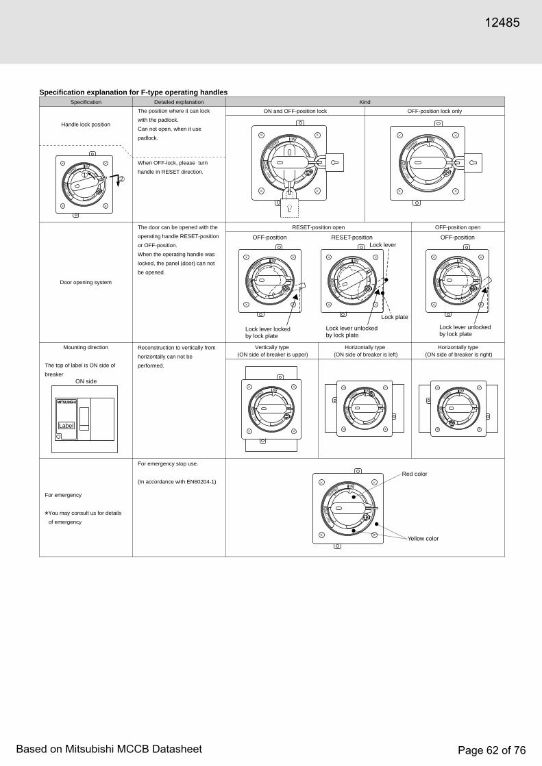
5
Specification explanation for F-type operating handlesSpecification Detailed explanation Kind
ON and OFF-position lock OFF-position lock only
RESET-position open OFF-position open
Vertically type (ON side of breaker is upper)
Horizontally type (ON side of breaker is left)
Horizontally type (ON side of breaker is right)
Handle lock position
Mounting direction
The top of label is ON side of
breaker
For emergency
*You may consult us for details
of emergency
The position where it can lock
with the padlock.
Can not open, when it use
padlock.
When OFF-lock, please turn
handle in RESET direction.
The door can be opened with the
operating handle RESET-position
or OFF-position.
When the operating handle was
locked, the panel (door) can not
be opened.
Door opening system
Reconstruction to vertically from
horizontally can not be
performed.
For emergency stop use.
(In accordance with EN60204-1)
SE ERT
OF F
TRIPPED
ON
SE ERT
OF F
TRIPPED
ON
SE ERT
OF F
TRIPPED
ON
SE ERT
OF F
TRIPPED
ON
SE ERT
OF F
TRIPPED
ON
SE ERT
OF F
TRIPPED
ON
SE ERT
OF F
TRIPPED
ON
SE ERT
OF F
TRIPPED
ON
SE ERT
OF F
TRIPPED
ON
SE ERT
OF F
TRIPPED
ON
Red color
Yellow color
12
Lock lever lockedby lock plate
OFF-position OFF-positionRESET-position
Lock lever unlockedby lock plate
Lock plate
Lock lever
Lock lever unlockedby lock plate
ON side
Label
12485
Based on Mitsubishi MCCB Datasheet Page 62 of 76

AccessoriesExternal Accessories
Table 5-25
–
–
–
– –
–
–
–
● External dimensions ● Drilling plan
5947
Operating plate
Operatingplate
max
. 145
114
130(
S4C
P·S
4SP
)18
0(S
100)
55
110
max
. 150
OF
F
TRIPON
Front panel
Decorative plate
(a)
84
25 102 ± 5
45
12
B ±
2A
± 2
D
35 ±
5
62
5.54-
Retainer
Front panelDeviation: 5mm or less110 or more (250 or more if hingeis mounted on the left)
Deviation: 2 mm or less
Centre of breaker
Hinge
Retainer(option)
Retainer*1
Center of breaker's handle
*1
*2
*5
*3
*3
84Front panel applicable thickness : 1.6 to 3.2
Reference planefor mounting the breaker
(b)
● Outside Dimension Diagram ● Front Plate Drilling Dimension Diagram
Operating plate
ON
OF
F
TRIP
45
110
114
80
Operating plateFront plate
Max
. 95
Max
. 115
34 40
Face plateø62
4-ø4.5 Center of the circuitbreaker
Deviationof 4mmor less
9
70
4770
Clasp(Note 1)
Clasp(Note 1)(Note 2)
Clasp(option)
(Not
e 3)
41.5
±4
(Note 3)43.5±4
Center of the circuit breakeroperating handle
17
Front plate deviation of 4mm or less100 or more (210 or more when the hinge is on the left)
Hinge
A±2 B±2
(Not
e 2)
C±2
Reference plane for mountingthe circuit breaker
ø12
Front plate thickness 1.2–3.2
ON
OFF
Fastening
Fastening ON
OFF
A16
BM5 screwfor attachingthe fastening
Center ofthe breaker
Center of thehandle of breaker Breaker
Notes: (1) The clasps are not supplied standardly, and should be prepared by users Details on dimensions and others will be available upon request. (2) When the optional clasp is used. (3) The tolerance from the center of ø62 is shown. (4) The dimensions of the front-face type are shown. Some of the back-face and plug-in types have a different reference plane for mounting the circuit breaker. (5) The front plate drilling dimensions for the U series differ from those shown above. Please consult us for their details.
Notes: *1. Retainers are not included. They must be provided by the customer.*2. When using optional retainer.*3. Shows the tolerance for the distance from the center of a 62mm dia. hole.*4. The figures show the front-connection dimensions. Some rear-connection and plug-in breakers have a different reference surface for mounting purposes.*5. S4CP and S4SP are for isolation purposes. (Specify OFF lock only.) The tolerance is less than 5mm. It does not conform to isolation purposes, however, if the deviation is more than 2mm.
Remark: The clamp for surface plate interlock fastener is common to 2P, 3P and 4P.
epyT epytrekaerBgiF )mm(snoisnemiD
lanretxEsnoisnemid nalpgnillirD A✳ 4 B✳ 4 C✳ 4 D
P *5C4S PC-004VN,PC-004FN a b 041 651 — 0
P *5S4S
S100
PER/PEH/PES/PS-004VN,PER/PEH/PES/PS-004FNPEH/PES/PS/PC-036VN,PER/PEH/PES/PS/PC-036FN
PEH/PES-008VN,PER/PEH/PES/PDS/PEC-008FN a b
a b
261 871 —
0
0
)P3(PEU-004FN 952 572 — 02PEU-008FN,PEU-036FN,)P4(PEU-004FN
NF1000-SS/SSD, NF1250-SS/SSDNF1600-SS/SSDNF1250-UR
952
199
203
215
219
572 —
—
—
5.32
3. S-type Operating Handle
● Surface plate interlocking fastening (separately available)
● Appearance (Color N1.5)
Table 5-24: Summary of Dimensions
● Appearance (Color N1.5)
● The handle can be locked at either ON or OFF position. (Three padlocks (40mm) can be installed. Off-position lock only specifications are also acceptable.)
● Digrees of protection (IEC60529) IP5X
● Indicates the tripping of the breaker even in ON-lock position--but only in cases when a single padlock(35mm) is used.
● Degrees of protection (in accordance with IEC60529): IP5X.
Type name Applicable modelsDimensions (mm)
A (Note 4) B (Note 4) C (Note 4)
S05SW NF32-SW, NF63-CW/SW/HW, NV32-SW, NV63-CW/SW/HW, MB30-SW, MB50-CW/SW87 102 104.5
S1SW NF125-CW/SW/HW, NV125-CW/SW/HW, MB100-SW, NV125-RW (Note 5)
S2SWNF160-SW/HW, NF250-CW/SW/HW, NV250-CW/SW/HWNV250-SEW/HEW, MB225-SW, NV250-RW (Note 5) 95 110 112.5
S2GSW NF125-SGW/HGW, NF160-SGW/HGW, NF250-SGW/HGW 113 128 130.5
Remark: (1) Trip action can be displayed when the circuitbreaker trips even if ON-position lock is selected(only in the case of a single padlock (35 mm)).
Remark: (1) Reset open-type(2) These are not suitable for isolation.
Operationhandle series
S-type
Type Drilling diagram and referential diagram
Drilling diagram
MCCB ELCB A BBreaker type Dimensions (mm)
NF32-SWNF63-CW/SW/HWMB30-SW, MB50-CW/SWNF125-CW/SW/HWMB100-SW
TG-S05SW
TG-S1UWTG-S05SP
TG-S2SW
TG-S2UW
TG-S2GSW
TG-S4CP
TG-S4SP
TG-S4UP
TG-S100
TG-S120UR
NF125-RGW/UGW
NF400-UEP (3P)NF400-UEP (4P), NF600-UEP, NF800-UEP
NF250-RGW/UGW
NF400-CP
NF1250-UR
NF160-SW/HWNF250-CW/SW/HWNF250-SEW/HEW,MB225-SW
NF125-SGW/HGWNF160-SGW/HGWNF250-SGW/HGWNF-SFW, NF-SJW, NF-HJW
NF400-SP/SEP/HEP/REPNF630-CP/SP/SEP/HEP/REPNF800-CEP/SDP/SEP/HEP/REPNF-SKW, NF-SLW
NF1000-SS/SSD, NF1250-SS/SSDNF1600-SS/SSD
NV32-SWNV63-CW/SW/HW
NV125-CW/SW/HW
NV125-RWNV100-SEP, HEP
NV250-RW
NV400-CP
67
6787
67
67
119
119119
119
119
NV250-CW/SW/HWNV250-SEW/HEW
NV400-SP/SEP/HEP/REPNV630-CP/SP/SEP/HEPNV800-SEP/HEP
Remark: (1) Reset open-type
12485

● Outside Dimension Diagram
● Mounting-hole Drilling Dimension Diagram
Handle
Center of thecircuit breaker
operating handle
Center of theoperating handle
Center of theoperating handle
Center of thecircuit breaker
Center of the circuitbreaker operating handle
Center of the circuitbreaker operating handle
2, 3-pole(a) (b) (c)4-pole
Circuit breaker
G G
FF F
JEither M4×0.7screw or ø5
Either M4×0.7screw or ø5
CL
CL CL
CL CL
(Note 1)
Center of thecircuit breaker
G
H
F Either M4×0.7screw or ø5
CL
CLCL
Note 1: The drilling at this position is not required for the models of R2GSW.
C
88D
E
A
B 88
16
(Note 1)
Table 5-27
K
L
Breaker
M6 screwor 7
4. R-type Operating Handle● Appearance (Color N1.5)
Table 5-26: Summary of Dimensions
● This handle in conjunction with the breaker main enables the isolation function effective.
● OFF-position lock only is available for up to three commercial padlocks (ø8).
● Equipped with cylinder key (option) prevent deliberate operation.
Type name Applicable modelsNumberof poles
Dimensions (mm)
A B C D E F G H J
R1SW NF125-CW, NF125-SW, NF125-HWNV125-CW, NV125-SW, NF125-HW
3P 90130
191
165
240
165
240
61
61
61
79
79
105
107
107
125
125
142
144
144
162
162
30
35
35
35
35
172
126
201
126
201
30.5
—
15
—
—
37.5
—
37.5
61 105 142 30 111 —
R1UW NV125-RW
NF160-SW, NF160-HW, NF250-CW, NF250-SW, NF250-HWNV250-CW, NV250-SW, NF250-HW, NV250-SEWNV250-HEW
R2SW
R2UW NV250-RW
NF125-SGW, NF125-HGW, NF160-SGW, NF160-HGW,NF250-SGW, NF250-HGWR2GSW
R2GUW NF125-RGW, NF125-UGW, NF250-RGW, NF250-UGW
4P
3P 90
2P, 3P
4P
3P
2P, 3P
4P
3P
120
105
140
105
105
140
105
✽ Equipped with cylinder key (option) to prevent deliberate operation.
—
17.5
—
—
—
17.5
(b)(a)
Outview External dimensions Drilling plan
● Can be locked in OFF position only.
a
c
b
a
b
c
a
b
c
Drillingplan
Fig
A B
E
D
C
G
F
J
H
epyTepytrekaerB giF )mm(snoisnemiD
BCCM BCLE OutviewgnillirD
nalpA B C D E F G H J K L
PWS4R,PES-004FN,PS-004FN,PC-004FN
PEH-004FN—
a b
752 821 041 041 52 34 79 471 812 491 44
VNPWS4R — ,PS-004VN,PC-004VNPEH-004VN,PES-004VN
PWS6R
,PES-036FN,PS-036FN,PC-036FNPEH-036FN
,PES-008FN,PDS-008FN,PEC-008FNPEH-008FN
572 821 012 041 52 34 79 471 812 342 07
M
—
—NV630-CP, NV630-SP,NV630-SEP, NV630-HEP,NV800-SEP, NV800-HEP
12485
Based on Mitsubishi MCCB Datasheet Page 64 of 76

AccessoriesExternal Accessories
V1)
12)
SW3)
E4)
F5)
1) V : Operating handle type
2) 1 : Frame size of breaker
3) SW : Series name
4) E : For emergency
5) F : Adjustment type of depth (For only V-handle)
6) NV : Type of breaker
Ordering information
NV6)
Variable-depth handleRotary handleNF32-SW, NF63-CW/SW/HW, MB30-SW, MB50-CW/SW, DSN32-SW, DSN63-CW/SW, NV32-SW, NV63-CW/SW/HWNF125-CW/SW/HW, NV125-CW/SW/HW, MB100-SW, DSN125-CW/SW, NV125-RWNF160-SW/HW, NF250-CW/SW/HW, MB225-SW, NV250-CW/SW/HW/SEW/HEW, DSN250-CW/SW, NV250-RW NF125-SGW/HGW, NF160-SGW/HGW, NF250-SGW/HGW, DSN125-SGW,DSN160-SGW, DSN250-SGW,NF125-RGW/UGW, NF250-RGW/UGWNF400-CP/SP/SEP/HEP/REP, DSN400-CP/SP, NV400/CP/SP/SEP/HEP/REP NF630-CP/SP/SEP/HEP/REP, DSN630-CP/SP, DSN800-CP/SP, NF800-CEP/SDP/SEP/HEP/REP, NV630-CP/SP/SEP/HEP,NV800-SEP/HEP
V·······R·······05·····
1·······
2·······
2G····
4·······
6·······
Blank······E············Blank······F············NV··········Blank······
For generalFor emergencyVariable typeFix typeNV type for 400A frameThe other
SW indicate WSSSPW indicate PSS
UW indicate WSS
C, S and H seriesC, S and H series
U series
F1)
12)
SW3)
A4)
R5)
1) F : Operating handle type2) 1 : Frame size of breaker
3) SW : Series name
4) A : Handle lock position
5) R : Door open position
6) Y : Mounting direction
7) 2P : Number of poles
8) NV : Type of breaker
Y6)
2P7)
NV8)
NF32-SW, NF63-CW/SW/HW, MB30-SW, MB50-CW/SW, DSN32-SW, DSN63-CW/SW, NV32-SW, NV63-CW/SW/HWNF125-CW/SW/HW, NV125-CW/SW/HW, MB100-SW, DSN125-CW/SW, NV125-RWNF160-SW/HW, NF250-CW/SW/HW, MB225-SW, NV250-CW/SW/HW/SEW/HEW, DSN250-CW/SW, NV250-RW NF125-SGW/HGW, NF160-SGW/HGW, NF250-SGW/HGW, DSN125-SGW,DSN160-SGW, DSN250-SGW,NF125-RGW/UGW, NF250-RGW/UGWNF400-CP/SP/SEP/HEP/REP, DSN400-CP/SP, NV400/CP/SP/SEP/HEP/REP, NF400-UEP NF630-CP/SP/SEP/HEP/REP, DSN630-CP/SP, DSN800-CP/SP, NF800-CEP/SDP/SEP/HEP/REP, NV630/CP/SP/SEP/HEP,NV800-SEP/HEP, NF400-UEP(4P),NF630-UEP, NF800-UEP
05·····
1·······
2·······
2G····
4·······
6·······
Blank······A············Blank······R············Blank······
Y············
Z············
Blank······2P···········NV··········Blank······
ON/OFF position lockOFF position lock onlyOFF position openRESET position openVertically type (ON side of breaker is upper)Horizontally type (ON side of breaker is left)Horizontally type (ON side of breaker is right)3 pole and 4 pole2 poleNV type for 400 to 800 A frameThe other
SW indicate WSSSPW indicate PSS
UW indicate WSSUPW indicate PSS
C, S and H seriesC, S and H series
U seriesU series
S1)
12)
SW3)
A4)
1) S : Operating handle type2) 1 : Frame size of breaker
3) SW : Series name
4) A : Handle lock position
NF32-SW, NF63-CW/SW/HW, MB30-SW, MB50-CW/SW, DSN32-SW, DSN63-CW/SW, NV32-SW, NV63-CW/SW/HWNF125-CW/SW/HW, NV125-CW/SW/HW, MB100-SW, DSN125-CW/SW, NV125-RWNF160-SW/HW, NF250-CW/SW/HW, MB225-SW, NV250-CW/SW/HW/SEW/HEW, DSN250-CW/SW, NV250-RW NF125-SGW/HGW, NF160-SGW/HGW, NF250-SGW/HGW, DSN125-SGW,DSN160-SGW, DSN250-SGWNF400-CP/SP/SEP/HEP/REP, DSN400-CP/SP, NV400/CP/SP/SEP/HEP/REP, NF400-UEP NF630-CP/SP/SEP/HEP/REP, DSN630-CP/SP, DSN800-CP/SP, NF800-CEP/SDP/SEP/HEP/REP, NV630/CP/SP/SEP/HEP, NV800-SEP/HEP, NF400-UEP(4P)NF630-UEP, NF800-UEP
05·····
1·······
2·······
2G····
4·······
S1)
1002)
1) S : Operating handle type2) 100 : Frame size of breaker
Blank······A············
ON/OFF position lockOFF position lock only
SW indicate WSSCP indicate PSSSP indicate PSS
C, S and H seriesC seriesS, H and U series
100·········NF1000-SS/SSD, NF1250-SS/SSD, NF1600-SS/SSD, NF1250-UR
F1)
1002)
1) F : Operating handle type2) 100 : Frame size of breaker
3) 4P : Number of poles
4P3)
100·········
120UR····Blank······4P··········
NF1000-SS/SSD, NF1250-SS/SSD, NF1600-SS/SSDNF1250-UR2 pole and 3 pole4 pole
12485
Based on Mitsubishi MCCB Datasheet Page 65 of 76

5
C
A
B C
A
B C
A
B C
A
B
C
A
B
Table 5-29
5. Terminal CoverTable 5-28
Breaker type
Large terminal cover(TC-L)
Small terminal cover(TC-S)
Transparent terminalcover (TTC)
Rear terminal cover(BTC)
Plug-in terminal cover(PTC)
NF32-SW, NF63-CW/SW/HW 2P TCL-05SW2W(50×65.5×25)
TCS-05SW2W(50×65.5×5)
TTC-05SW2(50×65.5×25)
BTC-05SW2W(50×65.5×5)
NF32-SW, NF63-CW/SW/HWNV32-SW, NV63-CW/SW/HW, MB30-SWMB50-CW/SW
3P TCL-05SW3W(75×65.5×25)
TCS-05SW3W(75×65.5×5)
TTC-05SW3(75×65.5×25)
BTC-05SW3W(75×65.5×5)
NF125-CW/SW/HW 2P
IP20
TCL-1SW2W(60×65.5×40)
TCS-1SW2W(60×65.5×6.5)
TTC-1SW2(60×65.5×40)
BTC-1SW2W(60×65.5×6.5)
NF125-CW/SW/HW, NV125-CW/SW/HW,NV125-RW, MB100-SW 3P TCL-1SW3W
(90×65.5×40)TCS-1SW3W(90×65.5×6.5)
TTC-1SW3(90×65.5×40)
BTC-1SW3W(90×65.5×6.5)
NF160-SW/HW, NF250-CW/SW/HW,NV250-CW/SW/HW, NV250-SEW/HEW, NV250-RWMB225-SW
2P3P
2P3P
TCL-2SW3W(105×65.5×40)
TCS-2SW3W(105×65.5×6.5)
TTC-2SW3(105×65.5×40)
BTC-2SW3W(105×65.5×6.5)
NF125-SGW/HGW/RGW/UGW, NF160-SGW/HGWNF250-SGW/HGW/RGW/UGW
IP40 TCL-2GSW3W(105×84×40)
TCS-2GSW3W(105×84×6.5)
TTC-2GSW3(105×84×40)
BTC-2GSW3W(105×84×6.5)
PTC-05SW2W(50×65.5×6.5)
PTC-05SW3W(75×65.5×6.5)
PTC-1SW2W(60×65.5×6.5)
PTC-1SW3W(90×65.5×6.5)
PTC-2SW3W(105×65.5×6.5)
PTC-2GSW3W(105×84×6.5)
Notes: (1) Attach the letter “F” to the end of model designation for models with F-type operating handle. (Those are F-type operating-handle dedicated models,and screws are used for fixing.)
(2) An F-type operating handle can be installed standardly.Remarks: (1) Parenthesized numbers denote the outside dimensions (A×B×C in mm).
(2) The terminal cover for a four-pole model can be produced upon request.
(Note 1)
(Note 2)
(Note 1)
(Note 2)
(Note 2)
(Note 1)
(Note 2)
(Note 1)
(Note 2)
(Note 2)
(Note 1)
(Note 2)
(Note 1)
(Note 2)
(Note 2)
NF30-CS, MB30-CS 2P TCL-03CS2W(43.5×30.5×25)
TCS-03CS2W(43.5×30.5×5)
TTC-03CS2(43.5×30.5×25)
BTC-03CS2W(43.5×30.5×6.5) —
NF30-CS, NV30-CS, MB30-CS 3P TCL-03CS3W(67×30.5×25)
TCS-03CS3W(67×30.5×5)
TTC-03CS3(67×30.5×25)
BTC-03CS3W(67×30.5×6.5) —
epytrekaerB
revoclanimretegraL)L-CT(
revoclanimrettnerapsnarT)CTT(
revoclanimretraeR)CTB(
revoclanimretni-gulP)CTP(
PER/PEH/PES/PS/PC-004FNPER/PEH/PES/PS/PC-004VN
P3,P23PS4-LCT
TCL-4SP3W ✳4
TCL-4SP3W ✳4
BTC-4SP3W ✳4
BTC-4SP3W ✳4
✳3
171( ✕ 5.99 ✕ )0111.giF
3PS4-CTT171( ✕ 5.401 ✕ )011
3PS4-CTB
041( ✕ 5.99 ✕ )24
3PS4-CTP041( ✕ 5.99 ✕ )24
PEU-004FN P33PS4-LCT ✳1
171( ✕ 5.691/5.231 ✕ )011—
3PS4-CTB ✳1
041( ✕ 5.691/5.231 ✕ )24—
PEH/PES-004VN,PEH/PES/PS-004FN P44PS4-LCT ✳4
042( ✕104.5✕110)
2.giF
4PS4-CTT042( ✕ 5.401 ✕ )011
4PS4-CTB ✳2581( ✕ 5.79 ✕ )93
—
PEH/PES/PS/PC-036VN,PER/PEH/PES/PS/PC-036FNPEH/PES-008VN,PER/PEH/PES/PDS/PEC-008FN
P3,P2
3PS6-LCT ✳5422( ✕103.5✕155)
3PS6-CTT422( ✕ 5.301 ✕ )551
3PS6-CTB ✳2012( ✕ 5.79 ✕ )23
—
PEU-008FN,PEU-036FN P3
2P, 3P
3PU6-LCT ✳1022( ✕ 5.491/641 ✕ )551
—3PS6-CTB ✳ ,1 ✳2
012( ✕ 5.491/641 ✕ )23—
PES-036VN,PEH/PES/PS-036FNPEH/PES-008FN
NF1000-SS/SSDNF1250-SS/SSD
NF1000-SS/SSD
NF1250-UR
NF1250-SS/SSD
NF1250-UR
P44PS6-LCT ✳6
492( ✕103.5✕155)4PS6-CTT
492( ✕ 5.301 ✕ )5514PS6-CTB ✳2
082( ✕ 5.79 ✕ )23—
PEU-008FN,PEU-036FN,PEU-004FN P4
P4
P3
P4
4PU6-LCT ✳1092( ✕ 5.491/641 ✕ )551
TCL-10SS3
TCL-10SS4
TCL-12UR3
TCL-12UR4
022( ✕ 0)51✕931
092( ✕ 0)51✕931
052( ✕ 0)32✕341
023( ✕ 0)32✕341
—
—
—
—
—
—
—
—
—
4PS6-CTB ✳ ,1 ✳2082( ✕ 5.491/641 ✕ )23
—
—
—
—
—
A(.mmnisnoisnemidlanretxeswohS)(.1:skrameR ✕B✕ )C✳ edisdaoL/ediseniL.1✳ .epytni-gulpnodetnuomebnacsrevocesehT.2✳ .PER/PEH-004VNdnaPER/PEH-004FNroftpecxE
Color is white..3
✳ .4
C
B
A
C
B
A
C
B
A
CB
A
Fig.2
Fig.1CB
A
12485
Based on Mitsubishi MCCB Datasheet Page 66 of 76
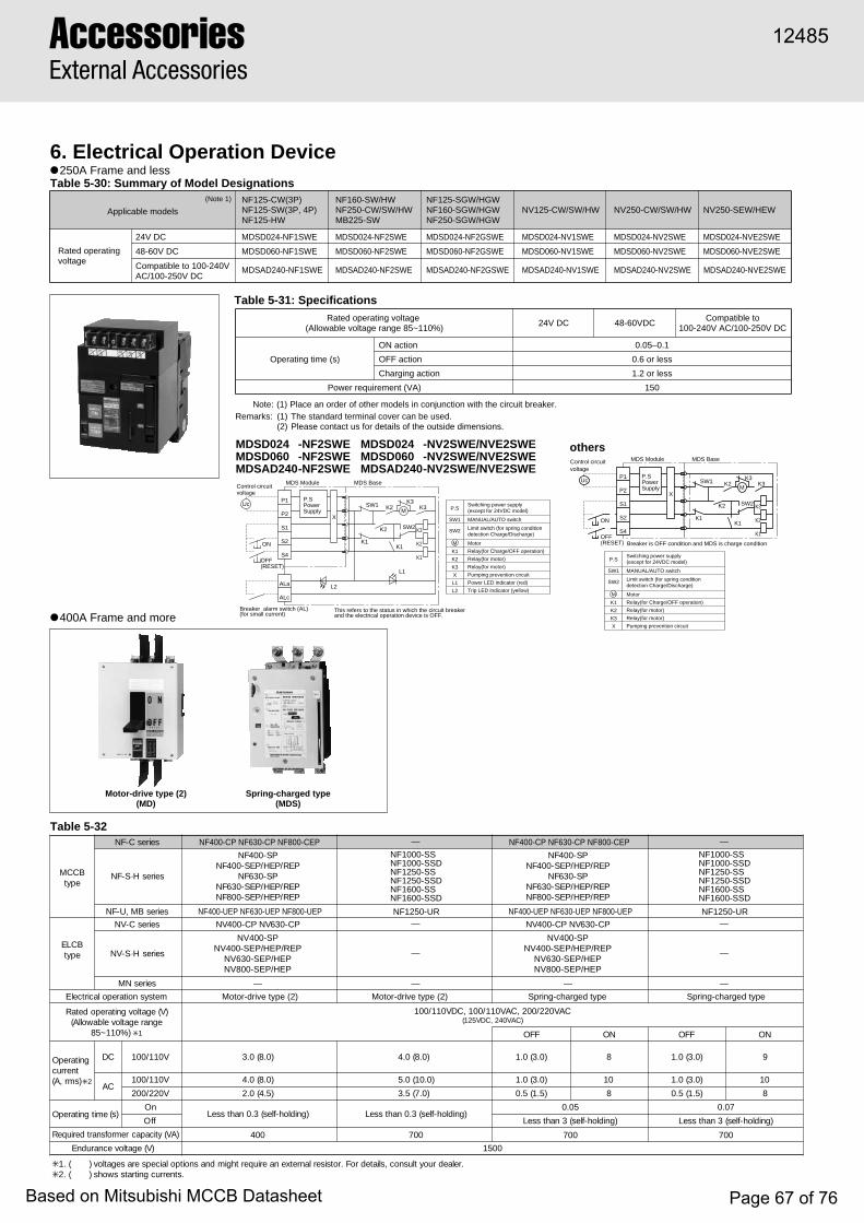
AccessoriesExternal Accessories
L2
ALc
X
This refers to the status in which the circuit breaker and the electrical operation device is OFF.
MDS Module MDS Base
ON
OFF(RESET)
P1
P2
S1
S2
S4
P.SPowerSupply
UcM
K1
K2
K3
K1K1
K2
K2K3
K3SW1
SW2
Control circuitvoltage
ALa
Breaker alarm switch (AL)(for small current)
L1
SW1
SW2
M
Switching power supply(except for 24VDC model)
MANUAL/AUTO switch
Limit switch (for spring condition detection Charge/Discharge)
Motor
P.S
Relay(for Charge/OFF operation)
Relay(for motor)
Relay(for motor)
K1
K2
K3
Pumping prevention circuitX
Power LED indicator (red)L1
Trip LED indicator (yellow)L2
SW1
SW2
M
Switching power supply(except for 24VDC model)
MANUAL/AUTO switch
Limit switch (for spring condition detection Charge/Discharge)
Motor
P.S
Relay(for Charge/OFF operation)
Relay(for motor)
Relay(for motor)
K1
K2
K3
Pumping prevention circuitX
X
Breaker is OFF condition and MDS is charge condition
MDS Module MDS Base
ON
OFF(RESET)
P1
P2
S1
S2
S4
P.SPowerSupply
UcM
K1
K2
K3
K1K1
K2
K2K3
K3SW1
SW2
Control circuitvoltage
6. Electrical Operation DeviceTable 5-30: Summary of Model Designations
Table 5-32
Table 5-31: Specifications
(Note 1)
Applicable modelsNF125-CW(3P)NF125-SW(3P, 4P)NF125-HW
NF160-SW/HWNF250-CW/SW/HWMB225-SW
NV125-CW/SW/HW NV250-CW/SW/HW NV250-SEW/HEW
Rated operating voltage
24V DC MDSD024-NF1SWE MDSD024-NF2SWE MDSD024-NV1SWE MDSD024-NV2SWE MDSD024-NVE2SWE
Compatible to 100-240V AC/100-250V DC
MDSAD240-NF1SWE MDSAD240-NF2SWE MDSAD240-NV1SWE
NF125-SGW/HGWNF160-SGW/HGWNF250-SGW/HGW
MDSD024-NF2GSWE
48-60V DC MDSD060-NF1SWE MDSD060-NF2SWE MDSD060-NV1SWE MDSD060-NV2SWE MDSD060-NVE2SWEMDSD060-NF2GSWE
MDSAD240-NF2GSWE MDSAD240-NV2SWE MDSAD240-NVE2SWE
Rated operating voltage (Allowable voltage range 85~110%)
24V DC 48-60VDCCompatible to
100-240V AC/100-250V DC
Operating time (s)
ON action 0.05–0.1
OFF action 0.6 or less
Charging action 1.2 or less
Power requirement (VA) 150
Note: (1) Place an order of other models in conjunction with the circuit breaker. Remarks: (1) The standard terminal cover can be used.
(2) Please contact us for details of the outside dimensions.
● 250A Frame and less
● 400A Frame and more
BCCMepyt
seiresC-FN
seiresS·H-FN
seiresBM,U-FN
BCLEepyt
seiresC-VN
seiresS·H-VN
seiresNM
metsysnoitarepolacirtcelE
NF1000-SSNF1000-SSDNF1250-SSNF1250-SSDNF1600-SSNF1600-SSD
NF1250-UR
—
—
—
—
Spring-charged type
)V(egatlovgnitarepodetaRegnaregatlovelbawollA(
)%011~58 ✳ 1
CAV022/002,CAV011/001,CDV011/001)CAV042,CDV521(
gnitarepOtnerruc)smr,A( ✳ 2
CD V011/001
CAV011/001
V022/002
NO
8
10
8
emitgnitarepO )s(nO 50.0
ffO )gnidloh-fles(3nahtsseL
remrofsnartderiuqeR )AV(yticapac 007 007
FFO
)0.3(0.1
)0.3(0.1
)5.1(5.0
NO
9
10
8
70.0
)gnidloh-fles(3nahtsseL
)V(egatlovecnarudnE
NF1000-SSNF1000-SSDNF1250-SSNF1250-SSDNF1600-SSNF1600-SSD
NF1250-UR
—
—
—
—
Motor-drive type (2)
)0.8(0.4
10.0)(0.5
)0.7(5.3
)gnidloh-fles(3.0nahtsseL
007
✳ .relaedruoytlusnoc,sliatedroF.rotsiserlanretxenaeriuqerthgimdnasnoitpolaicepserasegatlov)(.1✳ .stnerrucgnitratsswohs)(.2
FFO
)0.3(0.1
)0.3(0.1
)5.1(5.0
NF400-CP NF630-CP NF800-CEP
PS-004FNPER/PEH/PES-004FN
PS-036FNPER/PEH/PES-036FNPER/PEH/PES-008FN
NF400-UEP NF630-UEP NF800-UEP
PC-036VNPC-004VN
—
Motor-drive type (2)
)0.8(0.3
)0.8(0.4
)5.4(0.2
)gnidloh-fles(3.0nahtsseL
004
NV400-SPNV400-SEP/HEP/REP
NV630-SEP/HEPNV800-SEP/HEP
NF400-CP NF630-CP NF800-CEP
PS-004FNPER/PEH/PES-004FN
PS-036FNPER/PEH/PES-036FNPER/PEH/PES-008FN
NF400-UEP NF630-UEP NF800-UEP
PC-036VNPC-004VN
—
Spring-charged type
NV400-SPNV400-SEP/HEP/REP
NV630-SEP/HEPNV800-SEP/HEP
0051
MDSD024 -NF2SWE MDSD024 -NV2SWE/NVE2SWEMDSD060 -NF2SWE MDSD060 -NV2SWE/NVE2SWEMDSAD240-NF2SWE MDSAD240-NV2SWE/NVE2SWE
others
Motor-drive type (2)(MD)
Spring-charged type(MDS)
12485
Based on Mitsubishi MCCB Datasheet Page 67 of 76

5
General precautions for motor-operated electrical MCCBs● Motor-operated types have intermittent ratings, and therefore they
should not be operated more than 10 times consecutively (one on/off counts as an operation).
● The operating voltage should be between 85~110% of the rated control voltage.
● When the breaker is tripped by trip button or breakdown (i.e., overload or short circuit), the breaker will not show that it has been tripped (except for motor-operated type 1 breakers).
● The dielectric strength of the electrical operating circuits is 1500V. When performing a dielectric strength test simultaneously with another device at a voltage over 1500V, the operating circuit terminal should be disconnected.
Automatic Reset● If the breaker is an auto reset type, it contains a built-in alarm
switch and the off-control circuit closes when the breaker is tripped. Since the breaker automatically resets itself after tripping, the power is easily restored by switching on the breaker again. With a UVT mounted, however, auto reset may not be possible. In this case, please consult your dealer.
Motor-operated type (2)● Electrical operation Forward and reverse motor rotation is changed by ball screw to
switch the breaker ON and OFF (reset).● Manual operation The manual operation handle can be used to switch the breaker ON
and OFF directly.● Cautions during electrical operation1. In case the UVT operates and a circuit breaker trips if the breaker
has a UVT, the re-closing procedure may differ according to the state of the breaker before tripping.When the circuit breaker trips while turned ON..... Reset (OFF) -> Turn ONWhen the circuit breaker trips while turned OFF..... Turn ON (idle tripping) -> Reset (OFF) -> Turn ON (If it fails to turn ON (idle tripping), please operate Reset (OFF) and turn ON.)
2. Do not send ON and OFF signals consecutively. An interval of at least 0.5s is required between each ON and OFF.
3. For models with auto reset capability, resetting after an NFB trip should be performed after an interval of 0.5s.
4. The electrical operating device is equipped with a pumping prevention circuit. Although it is possible to set the device to OFF while it is set to ON, it is impossible to return it to ON immediately. To return to ON, first shut off the ON switch, then set it back to ON.
5. Special care is required during electrical operation because the manual operation handle moves at high speed. Also be sure to turn off the circuit power supply when using manual operation.
6. With manual operation, ensure that the handle is fully extended.
Control circuitThe dotted line shows an additional connection for the automatic-reset type.
Electrically Operated MCCBs and ELCBs
M
Earth terminal
(DC-)P2
P1
S1
S4
95
ON
OFFRESET
Operationalpower supply
ALa
T1
T1
T1T2
LS
T2
YY
Y
Y
Y
YX
X
X
X
X
Z ZZ
breaker is OFF state
M :MotorX :Relay for ON operationY :Relay for OFF operationZ :Relay for changing Motor polarityT1 :Timer for antipumpingT2 :Timer for automatic resetLS :Limit SwitchALa :Alarm switch for automatic reset (a contact)
Earth terminal
(DC-)P2
P1
S1
S4
95
ON
OFFRESET
Operationalpower supply
ALa
T1
T1T2 LS
Y
YX
YX
XY
YX
Z
Z
Z
XZ
M
X
Y
T2
(2) Control circuit 2. (NF1000-SS to NF 1600-SS)
(1) Control circuit 1. (400,630 and 800AF)
Manual operation Internal structure
12485
Based on Mitsubishi MCCB Datasheet Page 68 of 76

AccessoriesExternal Accessories
Control circuitThe dotted line shows an additional connection for the automatic-reset type.
Spring-charged type● Electrical operation When the ON switch is closed, the coil is excited to release the
latch mechanism and the force of the closing spring turns the breaker ON instantly.
When the OFF switch is closed, a relay starts the motor which turns the breaker OFF and charges the spring simultaneously.
● Manual operation Pressing the ON button will release the latch mechanism and the
force of the closing spring turns the breaker ON instantly. Pressing the leaf spring, pulling out the manual handle and pumping
it back and forth over 10 times will turn the breaker OFF and charge the spring at the same time.
● Cautions during electrical operation Whenever an electrical operation device is to be installed in or
removed from the breaker, the breaker must be tripped and the device discharged.
Pushing the TRIP button on an MCCB with an electrical-operation device installed will not trip the breaker in the OFF state. This does not mean the breaker is faulty.
Switching OFF a breaker with an electrical-operation device installed will take 3s. If instant opening is required, install an SHT or UVT to the breaker.
● The breaker contains a built-in pumping-prevention relay.
Internal connection
Earth terminal
(DC-) P2
P1
X
X
M
X
Y Y
YCC
LS1
LS2
LS3
S2
S4
ON
OFFRESET
Operationalpower supply
Alarm switch for automatic resetting (contact a)
CC.....Coil for makingY.....Relay for pumping preventionX.....Relay for self-sustaining on OFF sideLS1...Limit switch interlocking with camLS2...Limit switch interlocking with camLS3...Limit switch interlocking with OFF lock plateM....Motor
Ala
Internal structure
12485
Based on Mitsubishi MCCB Datasheet Page 69 of 76

5
max. 19
8
110–
111
30 30
S4S2S1P2P1S4S2S1P2P1
40
80
8825
4586
3941
163158
24
61
78
86
130
50
120
30
9090
111
8660
90 Display hole(Charge/Discharge)
M4x0.7 screwor ø5
4-pole3-pole
Circuit breaker
Front plate
Power supply module
Operating circuitterminal board(M3.5 screw)
M8 screw
Display hole(ON/OFF/TRIP)
OFF lock plateInsulation barrier(removable)
Trip button
ON button
Automatic/manualselectionswitch
Manual handle
(Conductor thickness t=5 max.)
ø8.5
Conductor drilling for direct connection
Drilling plan Font-plate cut out
Operating circuitterminal cover(standard supply)
Center of the electrically operated
Center of the electrically operated
Remarks:The 2-pole models are 3-pole models with the central pole removed.The three-pole type only is available for the model NF125-CW, and the3-pole and 4-pole types only are available for the model NF125-SW.
R1
ø8.5
(Conductor thickness t=7 max.)Conductor drilling for direct connection50
50
353778
79
176181
24
8645
11.5
358690
105140
144
165
708690105
126
35 35
8032
88
S4S2S1P2P1S4S2S1P2P1
max. 24
10
M4x0.7 screwor ø54-pole3-pole
Circuit breaker
Front plate
Power supply module
M8 bolt (Hex-soket)
Operating circuitterminal board(M3.5 screw)Display hole
(ON/OFF/TRIP)
OFF lock plateInsulation barrier(removable)
Trip button
ON button
Automatic/manualselectionswitch
Manual handle
Drilling plan Font-plate cut out
Operating circuitterminal cover(standard supply)
Center of the electrically operated
Center of the electrically operated
Display hole(Charge/Discharge)
R1
S4S2S1P2P1
8660
90
Display hole(ON/OFF/TRIP)
OFF lock plateInsulation barrier(removable)
Trip button
ON button
Automatic/manualselectionswitch
Manual handle
S4S2S1P2P1
86
130
50
120
30
9090
111
Center of the electrically operated
Display hole(Charge/Discharge)Test button
25
4586
3941
163158
24
61
78
Front plate
Power supply module
M8 screw
Operating circuitterminal board(M3.5 screw)
Operating circuitterminal cover(standard supply)
110–
111
30 30
M4x0.7 screwor ø54-pole3-pole
Circuit breaker
Drilling plan
40
80
88
Font-plate cut out
Center of the electrically operated
max.19
8
ø8.5
(Conductor thickness t=5 max.)Conductor drilling for direct connection
R1
● NF125-CW, NF125-SW, NF125-HW
● NF160-SW, NF160-HW, NF250-CW, NF250-SW, NF250-HW, MB225-SW
● NF125-SGW, NF125-HGW, NF160-SGW, NF160-HGW, NF250-SGW, NF250-HGW
● NV125-CW, NV125-SW, NV125-HW
● NV250-SEW, NV250-HEW
Front connection
Dimensions
(Bus t max=7)
Bus drilling for direct connection
max. 24
10
ø8.5
35
Breaker
4-pole3-pole Drilling planFont-plate cut out
Note.1.One AL(micro loads use)is used for the LED display for a trip indicator check.
2.2-pole breakers are 3-pole breakers with the central pole removed.
3.NF250-CW is available in 2-and 3-pole only.MB225-SW is available in 3-pole only.
Alarm switch AL(micro loads use)
105
708690
OPEN(TRIP)button
Breaker condition's indicator(ON/OFF)
MANUAL/AUTO switch
Electrical operation devicePower supply indicator LED(Red)
ON button
TRIP indicator LED(Yellow)
Insulating barrier(removable)
OFFlock plate
S4S2S1P2P1
140105
358690
Control circuit terminal Mounting screw(M3 tapping screw)
Center of MDS
Manual handle
144
165
100
100
S4S2S1P2P1
Hex.socket headM8 bolt
Control circuit terminal(M3.5 screw)
MDS base
33 31
15.5
4586 78
24
Terminal block for alarm switch AL connection (M4 screw) (with terminal cover)
Control circuit terminal cover
Front panel
MDS Module
61158163
M4X0.7 screwor 5mm-dia. hole
126
35
R1
80
88
Center of MDS
32
(Bus t max=7)
Bus drilling for direct connection
max. 24
10
ø8.5
Note.1.One AL(micro loads use)is used for the LED display for a trip indicator check.
2.4-pole breakers are only NV250-SEW.
33 31
15.5
4586 78
24
61158163
Hex.socket headM8 bolt
Control circuit terminal(M3.5 screw)
MDS baseTerminal block for alarm switch AL connection (M4 screw) (with terminal cover)
Control circuit terminal cover
Front panel
MDS Module
35
Breaker
4-pole3-pole Drilling plan
M4X0.7 screwor 5mm-dia. hole
126
35
32
80
88
Font-plate cut out
R1
Center of MDS
Test button
140105
358690
144
165
100
100
Control circuit terminal Mounting screw(M3 tapping screw)
Center of MDS
Manual handle
S4S2S1P2P1
105
708690
Alarm switch AL(micro loads use)
Breaker condition's indicator(ON/OFF)
MANUAL/AUTO switch
Electrical operation devicePower supply indicator LED(Red)
TRIP indicator LED(Yellow)
Insulating barrier(removable)
OFFlock plate
OPEN(TRIP)button
ON button
S4S2S1P2P1
12485
Based on Mitsubishi MCCB Datasheet Page 70 of 76

AccessoriesExternal Accessories
● NF400-CP, NF400-SP, NF400-SEP, NF400-HEP, NF400-REP Motor drive type (2)
● NF630-CP, NF630-SP, NF630-SEP, NF630-HEP, NF630-REP Motor drive type (2)
● NV400-CP, NV400-SP, NV400-SEP, NV400-HEP, NV400-REP Motor drive type (2)
● NF400-UEP (3-pole) Motor drive type (2)
Trip button
Insulating barrierCenter line of electrical operationdevice and breaker
Center line of breaker
Breaker Operating circuit terminalblock M3.5 screw
4-pole2, 3-pole
4-pole2, 3-pole
Drilling plan
120 70
231
194
257
16 4311
0
277
44
112
Remark: 2 pole models are 3-pole models with the central pole removed.
140231
44
44Conductor thickness t=8 max.
ø14M12 bolt
94.5195
255
44
8Breaker
M6tap or ø7
Center line of electrical operation device
168185196
22 2856
44
Trip button
Insulating barrierCenter line of electrical operation device and breaker
Center line of breaker
BreakerOperating circuit terminal block M3.5 screw
Drilling plan
23470
120
277
297
257
110
110
112140231
44
127.578
144
Conductor thickness t=8 max.
ø14M12 bolt
47ø7
ø12.
5
141191.5
292352
8Breaker
M6 tap or Ø7
Center line of electrical operation device
44
28
16
20
4343
ø7ø12.
5
Trip button
Insulating barrierCenter line of electrical operationdevice and breaker
Center line of breaker
Breaker Operating circuitterminal block M3.5 screw
4-pole3-pole
4-pole3-pole
Drilling plan
120 70
23119
4
257
16 4311
0
277
44
112140231
44
44Conductor thickness t=8 max.
ø14M12 bolt
94.5195
255
44
8Breaker
M6tap or ø7
Center line of electrical operation device
168185196
22 2856
44
Test button
Insulating barrierCenter line of electrical operationdevice and breaker
Center line of breaker
Breaker
Operating circuit terminal blockM3.5 screw
4-pole2, 3-pole
2,3-pole
Drilling plan
120 70
243
87328
1527
5
277
110
44
140
Remark: 2 pole models are 3-pole models with the central pole removed.
210231
70
44
Conductor thicknesst=8 max.
ø14M12 bolt
94.5195
255
44
8
Breaker
Neutral poleM6tap or ø7
Center line of electrical operation device
7035 40
210280
231
4-pole
70
Trip button
Front connection
12485
Based on Mitsubishi MCCB Datasheet Page 71 of 76

5
● NF630-UEP (NF400-UEP 4-pole) Motor drive type (2)
● NF800-UEP Motor drive type (2)
● NF800-CEP, NF800-SDP, NF800-SEP, NF800-HEP, NF800-REP Motor drive type (2)
● NV630-CP, NV630-SP, NV630-SEP, NV630-HEP Motor drive type (2)
Insulating barrier
Center line of electrical operationdevice and breaker
Center line of breaker
Center line of breaker Center line of breaker
Breaker
Operating circuitterminal blockM3.5 screw
4-pole3-pole
Drilling plan
(NF400-UEP 4-pole)
87
328
1587
Conductorthicknesst=8 max.
Conductor thicknesst=8 max.
ø14M12 bolt
ø14M12 bolt
Breaker
Neutral pole
M6 tapor ø7
Center line of electricaloperation device
Center line of electricaloperation device
Center line of electricaloperation device
120 70
23.5
110
277
Operating circuitterminal block M3.5 screw
Neutral pole
44
140210231
1440
4-pole3-pole
7032
2
210280
231
3570
48
1648 11
0
35
322
290
140
290
210280
231
358141
191.5292
352
112
15
8
14397
ø14
ø14
ø7
275
70
ø7
6.5141
191.5292
352
112
15
6.5
14397
ø14
ø14
ø7
275
ø7
Trip button
Insulating barrierCenter line of electrical operationdevice and breaker
Center line of breaker
Breaker
Operating circuitterminal block M3.5 screw
4-pole3-pole
3-pole
Drilling plan
120 70
243
87328
1527
5
277
110
44
140210231
70
44Conductorthicknesst=8 max.
ø14M12 bolt
94.5195
255
44
8
Breaker
Neutralpole
Center line of electrical operation device
7035 40
210280
231
4-pole
70
Trip button
M6 tapor ø7Test
button
Trip button
M6 tapor ø7
Insulating barrierCenter line of electrical operationdevice and breaker
Center line of breaker
Breaker
Operating circuit terminalblock M3.5 screw
4-pole2, 3-pole
2, 3-pole
Drilling plan
120 70
243
87328
1527
5
277
110
44
140
Remark: 2 pole models are 3-pole models with the central pole removed.
210231
70
46Conductorthicknesst=12 max.
ø14M12 bolt
94.5195
255
46
8
Breaker
Neutralpole
Center line of electrical operation device
7035 40
210280
231
4-pole
70
Trip buttonM6 tapor ø7
Insulating barrier
Center line of electrical operationdevice and breaker
Center line of breaker
Center line of breaker
Breaker
Operating circuitterminal blockM3.5 screw
4-pole3-pole
Drilling plan
87
328
1587
Conductor thicknesst=8 max.
ø14M12 bolt
Breaker
Neutral pole
Center line of electricaloperation device
Center line of electricaoperation device
120 70
23.5
110
277
44
140210231
1440
4-pole3-pole
70
322
210280
231
3570
290
140
290
8143
191.5292
352
112
15
8
14364
ø14
ø14
ø7
275
ø7
Front connection
12485
Based on Mitsubishi MCCB Datasheet Page 72 of 76
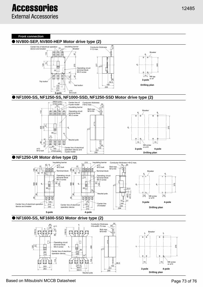
AccessoriesExternal Accessories
● NV800-SEP, NV800-HEP Motor drive type (2)
● NF1600-SS, NF1600-SSD Motor drive type (2)
● NF1250-UR Motor drive type (2)
● NF1000-SS, NF1250-SS, NF1000-SSD, NF1250-SSD Motor drive type (2)
Trip button
Test button
Insulating barrierCenter line of electrical operationdevice and breaker Breaker
Operating circuitterminal blockM3.5 screw
3-pole
3-pole
Drilling plan
120 70
110
243
277
44
14040
210231
14
70
46Conductor thicknesst=12 max.
ø14M12 bolt
94.5195
255
46
8
Breaker
M6 tapor ø7
87328
15
275
87
M8 screwor ø10
Bolt max.M10×65
Conductor thicknesst=6×width 75 max.ø11
375
203263
290
140231
69.5
Center line of electricaloperation device
20
70
Operating circuitterminal blockM3.5 screw
Neutral pole
Breaker
115
(185
.5)
3815
3860
44210
6112
0
Drilling plan4-pole3-pole
70
304.5101.5
364.5
130
406
(185
.5)
55
35210280
Insulating barrier
Terminal block
Center line of electrical operationdevice and breaker
Center lineof breaker
Operating circuitterminal blockM3.5 screw
4-pole3-pole
Drilling plan
Conductor thickness t=8×2 max.
Bolt max.M12×50
ø13M12 bolt
Breaker
Neutral poleM8 screwor ø10
Center line of electricaloperation device
106
6112
0
Insulating barrierø13M12 bolt
Terminal block
Operating circuitterminal blockM3.5 screw
44
140210240
43
13815
3280
406
4-pole3-pole
70
8080
566
375
51
22.5
15144
235294
15 44
ø9.5
ø17.
5
70
106
6112
0
44
70140
210310
43210
13
815
3280
406
8080
566
Insulating barrier
Center line of4-pole model
Center line of electricaloperation device and3-pole model
Operating circuitterminal blockM3.5 screw
Drilling plan
120 61
406
110
80
375
44
14043
13
70210(4-pole)
210(3-pole)
280(4-pole)
70
55Conductor thicknesst=8×2 max.
Bolt max.M12×50
ø13M12 bolt
140231
290
59
15
Breaker
Neutral pole
M8 screwor ø10
70
4-pole3-pole
328
15
Front connection
12485
Based on Mitsubishi MCCB Datasheet Page 73 of 76

5
● NF1600-SSD (4-pole) Motor drive type (2)
● NF1600-SSD Motor drive type (2)
● NF1600-SS (4-pole) Motor drive type (2)
● NF1600-SS (3-pole) Motor drive type (2)
210
35
406
ø 9.5
M8 tapor ø10
ø11M10×50 bolt
ø17.
5
109
1854
15
269
81.5
over
160
unde
r 100
38
273
20
18.515
70210
231
290 125Center line of electricaloperation device
38 1860
106 106318
70
Mounting angle
Mounting angleOperating circuitterminal blockM3.5 screw
Connectionallowance Conductor thickness
t=6×width 75 max.
Stud can be rotated 90°Breaker
280
20
44
6112
0
Drilling plan4-pole
406
ø9.5
36
M8 tapor ø10
ø11M10×50 bolt
ø17.
5
109
233
38 60
375
over
160
over
175
20
18.515
210
140 231
290 200
125 38
38 15
15 21270
Mounting angleMounting angleOperating circuit terminal block
M3.5 screw Connectionallowance
Conductor thicknesst=6×width 75 max.
Stud can be rotated 90° Breaker
44
6112
0
Drilling plan3-pole
406
ø 9.5
M8 tapor ø10
ø11M10×50 bolt
ø17.
5
109
273
38 60
269
over
160
81.5
20
18.515
36
210
140 231
290 200
125 38
38 15
15 21270
Mounting angleMounting angleOperating circuit terminal blockM3.5 screw Connection
allowanceConductor thicknesst=6×width 75 max.
Stud can be rotated 90° Breaker
44
6112
0
unde
r10
0
Drilling plan3-pole
210
35
406
ø9.5
M8 tapor ø10
ø11M10×50 bolt
ø17.
5
109
15
375
over
160
over
175
38
233
20
18.515
70210
231
290 125Center line of electricaloperation device
38 1860
106 106318
70
Mounting angle
Mounting angleOperating circuitterminal blockM3.5 screw
Connectionallowance Conductor thickness
t=6×width 75 max.
Stud is in horizontal direction.Stud can not be rotated 90°.
Breaker
280
44
6112
0
Drilling plan4-pole
Rear connection
12485
Based on Mitsubishi MCCB Datasheet Page 74 of 76

AccessoriesExternal Accessories
● Outside Dimension Diagram (Front connection, Rear connection, and Plug-in)
● Drilling Dimension Diagram (Front connection, Rear connection, and Plug-in)
Panel plate thickness(t1~3.2)
(Gap between the circuit breaker and the panel)
15 Stroke
Center of circuit breaker
Center of mechanical interlock
Center of circuit breaker
Center of mechanical interlock
Machine this part according to the front plate drilling dimensions of the main breaker.
4ø (ø5.5 and ø7.5 countersunk (rear) (Note 1)); use M5×0.8 flat countersunk head screws to fix.
1.5
33
70
50
120 (Note 2)
A
22
31 15.5
44
13
63 (N
ote
3)
Notes: (1) When the panel plate thickness is 2.3 or more, prepare four holes (ø5.5 and ø9.5 countersunk (rear)).
(2) These are standard dimensions for 2- and 3-pole models, but can be altered upon request.
(3) The U series have different dimensions. Please contact us for details.
Remarks: (1) Please contact us for outside dimensions of other models of different specifications.
(2) These are not isolation-compatible.
Mechanicalinterlock
Breaker
A
50
DP
B
E
2244
31 15.5
C
Stroke
70
Panel thickness(t1~3.2mm)
Gap between paneland breaker
Differs with mainbreaker unit drilling plan.
Mounts to 4-5.5mm-dia hole,7.5mm-dia countersunk (rear)*2
Mechanicalinterlock
Breaker
Mechanical interlock
Drilling planFig.1 Fig.2 Fig.3
Drilling plan
External dimensions
Mechanicalinterlock
Breaker
70(100)
A
31(4
0)
15.5
(20)
C
50(80)
P
44(5
5)
22(3
0)
B
Mechanicalinterlock
Breaker
Panel thickness(t1.6~3.2mm)Stroke
1.5
Gap between paneland breaker
External dimensions
Differs with mainbreaker unit drilling plan.
Mounts to 4-5.5mm-dia hole,7.5mm-dia countersunk (rear)*2
( ) dimension are shown for NF1600-SS·NF1600-SSD
G
FFP
47.5 Stroke
94.5
45
P
Mechanical interlock
External dimensions
Drilling plan(breaker mount)
Breaker
Breaker
M6 screwsor 7mm-dia
Mechanical terminal mount
7. Mechanical Interlocks (MI)Table 5-33
Table 5-34
Front, Rear, Plug-in (panel mounting)
Breaker mounting (front)
S1. Above 400AF, use panel thickness t=1.6~3.2mm.S2. When the panel thickness is greater than t=2.3mm, use 4-5.5mm-dia 9.5mm dia countersunk (rear).
Numberof poles Front connection, Rear connection, Plug-in Dimension A mm
47.5–
45
–
Direct mount oncircuit breaker
NF32-SW, NF63-CW/SW/HW 2PMI-05SW3
–NF32-SW, NF63-CW/SW/HW, NV32-SW, NV63-CW/SW/HW, MB30-SW, MB50-CW/SW 3P MI-05SWFB3NF63-SW/HW 4P MI-05SW4 –NF125-CW/SW/HW 2P
MI-05SW3–
NF125-CW/SW/HW, NV125-CW/SW/HW, MB100-SW, NV125-RW
NF160-SW/HW, NF250-SW/HW, NV250-SW/HW/SEW/HEWNF125-SGW/HGW/RGW/UGW, NF160-SGW/HGW, NF250-SGW/HGW/RGW/UGWNF125-SGW/HGW/UGW, NF160-SGW/HGW, NF250-SGW/HGW/UGW
3P4P
MI-1SWFB3MI-1SW4 –
NF160-SW/HW, NF250-CW/SW/HW, NV250-CW/SW/HW, NV250-SEW/HEW, MB225-SW, NV250-RW
2P3P MI-05SW3 MI-2SWFB3
MI-2GSWFB3–
4P3P4P
MI-2SW4MI-05SW3MI-2SW4
–
Panel moutingApplicable models
epyT F G P3BFPS4-IM 44 491 0913BFPS6-IM 07 342 062
epytrekaerB )mm(snoisnemiD
BCCM BCLEdradnatS laicepS
dradnatS dradnatSt A B D E .giF
epyT.giF
epyT P2 P3 P3 epyT P4 P3PER/PEH/PES/PS/PC-004FN PER/PEH/PES/PS/PC-004VN
3PS4-IM091
– 012 4PS4-IM 052(✳ )2
–
5.74 335.38
– 47
1.giF
2.giF
3BFPS4-IM
3.giF)P3(PEU-004FN – – 091 5.36 –
,PER/PEH/PES/PS/PC-036FNPER/PEH/PES/PDS/PEC-008FN
,PEH/PES/PS/PC-036VNPEH/PES-008VN 3PS6-IM
M-10SS3 220
315M-12UR3M-16SS3
022042
–
–
––
–––
4PS6-IM
MI-10SS4MI-12UR4MI-16SS4
092
02.3
92023624
5.74
5.745.74
65
33
7474
4.55 937.537.53
5.38–
–––
–––
–––
–––
473BFPS6-IM
,PEU-036FN,)P4(PEU-004FNPEU-008FN
NF1000-SS/SSD, NF1250-SS/SSDNF1250-URNF1600-SS/SSD
–
–––
– 022
– 052
06 –
✳ yficepS.1 )P(hctipgnitnuomrekaerbeht✳ ).mm2.3~6.1=tssenkcihtlenapesu,FA004evobA.mm2.3~1=t:egnarssenkcihtlenapelbasU(.)t(ssenkcihtlenapehtyficepsotdeenoN.2✳ nihtiwnoitaivednoisnemidCehtpeek,sledomFA008/036/004htiwsesoprupnoitalosiroF.3 ± .mm1✳ .sliatederomroferiuqnE.4
Mechanical interlock walking type (MI-W) for electrical operating:skrameR )FA004evobA(.relaedruoytlusnoC.redrootedamebnac
Pitch (P) ✳1
C(✳3)
Breaker mount(✳4)
● Front, Rear, Plug-in
● Table of Altered Dimensions
With two breakers, use a panel-mounted mechanical interlock for one-way only input.A breaker-mounting mechanical to mount on the breaker main unit can be made to order. Consult your dealer for more details.
12485
Page 75 of 76

5
CL
6
M4×0.7 screw
35
13
7
CLCL
Mounting hookfor IEC 35mm rail
Fig.2Fig.1 Fig.3
4
5
35
Adapter for IEC 35mm rail
8. Handle Lock Devices and Card HolderTable 5-35
Table 5-36
9. IEC 35mm Rail Mounting AdaptersTable 5-37
Notes: (1) HLF types are used for OFF-lock, and HLN types for ON-lock.(2) HL-S types are used for OFF-lock.
Remark: (1) Users are requested to prepare padlocks for HL and HL-S types. (25mm padlock for HL, and 35mm padlock for HL-S.)
Applicable models Number of poles Parts number Outline
NF32-SW, NF63-CW/SW/HWNV32-SW, NV63-CW/SW/HW, MB30-SWMB50-CW/SW
DIN-05SW Fig.2
Fig.3
Fig.1
2P3P
NF125-CW/SW
NF30-CS, NV30-CS, MB30-CS
2P
2P, 3P
DIN-1SW2
DIN-03CS
3P
DIN-1SW3NF125-HW, NV125-CW/SW/HW, MB100-SW
2P3P
Description Lock cover (LC) Handle lock (HL) Handle lock (HL-S) (Note 2) OFF Lock with 3 Padlock Card holder
Appearance
NF32-SW, NF63-CW/SW/HW 2P
NF30-CS, NV30-CS, MB30-CS 3P
NF30-CS, MB30-CS 2P
LC-05SW
LC-03CS
(Note 1)
HLF-05SWHLN-05SW
HLS-05SW2P
—
——
NF32-SW, NF63-CW/SW/HW, NV32-SW, NV63-CW/SW/HWMB30-SW, MB50-CW/SW
3PHLS-05SW
NF63-SW/HW 4P
NF125-HW 2P
NF125-CW/SW 2P
LC-1SW
(Note 1)
HLF-1SWHLN-1SW
HLS-1SW2P
NF125-CW/SW/HW, NV125-CW/SW/HWMB100-SW, NV125-RW
3PHLS-1SW
NF125-SW/HW, NV125-SW/HW 4P
NF160-SW/HW, NF250-CW/SW/HW, NV250-CW/SW/HWNV250-SEW/HEW, MB225-SWNV250-RW
2P3P4P
LC-2SW
(Note 1)HLF-2SWHLN-2SW
HLS-2SW
NF125-SGW/HGW, NF160-SGW/HGW, NF250-SGW/HGWNF125-RGW/UGW, NF250-RGW/UGW 3P, 4P LC-2GSW
HLF-2GSW (Note 1)
HLN-2GSW
HL-05FH
HLS-2GSW HLF3-2GSW
tcudorP )TH(eldnaH )LH(kcoleldnaH )S-LH(kcoleldnaH redlohdraC
epytrekaerB
PC-004VN,PC-004FN TH - PC4 LH - C4S4-SLH
3.oNP-HC
PEU/PER/PEH/PES/PS-004FNPER/PEH/PES/PS-004VN
TH
HT-10SS
- PS4 LH - S4
)P3(PEU-004FN U4-SLH
)P4(PEU-004FNPEU/PER/PEH/PES/PS/PC-036FN
PEH/PES/PS/PC-036VNPEU/PER/PEH/PES/PDS/PEC-008FN
PEH/PES-008VN
NF1000-SS/SSDNF1250-SS/SSDNF1250-URNF1600-SS/SSD
HLS-6SP (✳ 1)HLS-6UP (✳ 3)
:skrameR.remotsucehtybdedivorpebtsumS-LHdnaLHrofskcoldaP.1 ✳1. Must be ordered with breaker.
✳2. The HL without padlock can be used as a lock cover (LC). ✳3. Applicable types are NF400-UEP (4P) and NF630/800-UEP (3P, 4P).
—
P (✳1·2)P (✳1)
HL (✳1)
P (✳1·2)
P (✳1)
CH-P No.5
8
100
35
1
3
Adapter for IEC 35mm rail
12485
Based on Mitsubishi MCCB Datasheet Page 76 of 76


![MCCB Range [8536] With Thermal - Magnetic Releaseindersonsindia.com/download.php?f=5bcaa450349b115... · for cost effective MCCB for motor starter application MCCB Range ... dsine/DU](https://static.fdocuments.us/doc/165x107/5aaf45057f8b9a3a038d267e/mccb-range-8536-with-thermal-magnetic-r-cost-effective-mccb-for-motor-starter.jpg)