Coursing Tables, Metric Shapes and Sizes -...
13
w w w . c c m p a . c a Coursing Tables, Metric Shapes and Sizes By Gary Sturgeon, B.Eng., MSc., P.Eng. Technical Services Engineer, CCMPA
Transcript of Coursing Tables, Metric Shapes and Sizes -...

w w w . c c m p a . c a
Coursing Tables, Metric Shapes and Sizes
By Gary Sturgeon, B.Eng., MSc., P.Eng.Technical Services Engineer, CCMPA
w w w . c c m p a . c a 3-1
Coursing Tables, Metric Shapes and Sizes
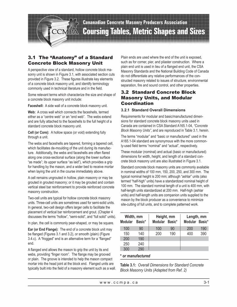
3.1 The “Anatomy” of a Standard Concrete Block Masonry UnitA perspective view of a standard, hollow concrete block ma-sonry unit is shown in Figure 3.1, with associated section cuts provided in Figure 3.2. These figures illustrate key elements of a concrete block masonry unit, and identify terminology commonly used in technical literature and in the field.
Some relevant terms which characterize the size and shape of a concrete block masonry unit include:
Faceshell: A side wall of a concrete block masonry unit.
Web: A cross wall which connects the faceshells, termed either as a “centre web” or an “end web”. The webs extend and are fully attached to the faceshells to the full height of a standard concrete block masonry unit.
Cell (or Core): A hollow space (or void) extending fully through a unit.
The webs and faceshells are tapered, forming a tapered cell, which facilitates de-moulding of the unit during its manufac-ture. Additionally, the webs and faceshells are often flared along one cross-sectional surface (along the lower surface “as made”; its upper surface “as laid”), which provides a grip for handling by the mason, and a wider bed to receive mortar when laying the unit in the course immediately above.
A cell remains ungrouted in hollow, plain masonry or may be grouted in grouted masonry; or it may be grouted and contain vertical steel bar reinforcement to provide reinforced concrete masonry construction.
Two-cell units are typical for hollow concrete block masonry units. Three-cell units are sometimes used for semi-solid units. In general, two-cell design offers larger cells to facilitate the placement of vertical bar reinforcement and grout. (Chapter 4 discusses the terms “hollow”, “semi-solid”, and “full solid” units).
In plan, the cell is commonly pear-shaped, or may be square.
Ear (or End Flange): The end of a concrete block unit may be flanged (Figures 3.1 and 3.2), or smooth (plain) (Figure 3.4.c). A “frogged” end is an alternative term for a “flanged” end.
A flanged end allows the mason to grip the unit by its end webs, providing “finger room”. The flange may be grooved or plain. The groove is intended to help the mason compact mortar into the head joint at the block end. Flanged units are typically built into the field of a masonry element such as a wall.
Plain ends are used where the end of the unit is exposed, such as for corner, pier, and pilaster construction. Where a plain end unit is used in lieu of a flanged end unit, the CSA Masonry Standards and the National Building Code of Canada do not differentiate any relative performances of the con-structed masonry related to issues of structure, environmental separation, fire and sound control, and other properties.
3.2 Standard Concrete Block Masonry Units, and Modular Coordination 3.2.1 Standard Overall DimensionsRequirements for modular and basic/manufactured dimen-sions for standard concrete block masonry units used in Canada are contained in CSA Standard A165.1-04, “Concrete Block Masonry Units”, and are reproduced in Table 3.1, herein.
The terms “modular” and “basic or manufactured” used in the A165.1-04 standard are synonymous with the more common-ly-used field terms “nominal” and “actual”, respectively.
These modular (nominal) and actual (basic or manufactured) dimensions for width, height, and length of a standard con-crete block masonry unit are also illustrated in Figure 3.1.
Standard concrete block masonry units are commonly available in nominal widths of 100 mm, 150, 200, 250, and 300 mm. The typical nominal height is 200 mm; although “ashlar” units (also termed “half-high” units) have a standardized nominal height of 100 mm. The standard nominal length of a unit is 400 mm, with half-length units standardized at 200 mm. Half-high (ashlar units) and half-length units are companion units supplied to the mason by the block producer as a convenience to minimize site-cutting of full units, and to complete patterned work.
Table 3.1: Overall Dimensions for Standard Concrete Block Masonry Units (Adapted from Ref. 2)
Width, mm Height, mm Length, mm Modular Basic* Modular Basic* Modular Basic*
100 90 100 90 200 190 150 140 200 190 400 390 200 190 250 240 300 290
* or manufactured

w w w . c c m p a . c a3-2
Coursing Tables, Metric Shapes and Sizes
The actual dimensions of width, height and length are 10 mm less than the nominal dimensions of a unit, respectively, to accommodate a standard 10 mm mortar joint. By doing so, modular dimensions in all three directions are maintained.
It is common practice when identifying or specifying concrete block masonry units to state the block nominal width, the block (course) nominal height, and the block nominal length, in this order. Hence, a 150 x 200 x 400 mm unit has:
• nominal overall dimensions of: 150 mm wide x 200 mm high, x 400 mm long; and,
• actual overall dimensions of: 140 mm wide x 190 mm high x 390 mm long.
The most commonly used units in Canada for loadbearing structural applications are the 200 and 250 mm nominal width units.
3.2.2 Permissible Dimensions and Permissible VariationsRequirements for permissible dimensions, and permissible variations in dimensions for concrete block masonry units used in Canada are contained in CSA A165.1-04.
For standard concrete block masonry units, CSA A165.1-04 requires the minimum faceshell and web thicknesses shown in Table 3.2.
Actual dimensions of the unit are determined by the producer or certified testing agency by appropriate sampling and physi-
cally measuring units using calipers in accordance with the procedures of ASTM C 140-03, “Standard Test Methods for Sampling and Testing Concrete Masonry Units and Related Units”.
The minimum thicknesses for faceshells and webs are as-signed by the A165.1-04 standard based upon the modular (nominal) width of the unit. They refer to the most limiting width of a tapered faceshell or web in the unit, that is, to the narrowest cross-section and to the average thicknesses mea-sured. In addition to these dimensional limits, the equivalent web thickness (the sum of the minimum web thicknesses in the unit) is assigned a minimum percentage of the overall length of the unit. This ensures that sufficient web material ex-ists to transfer imposed loads in-service from one faceshell to the other faceshell and that unit integrity is maintained during manufacture and handling.
Placing limits on faceshell and web thicknesses ensures that the fundamental assumptions used to predict the performance of masonry elements constructed with standard concrete block units are met under the actions of structural and non-structural loads. For example, CSA S304.1, “Design of Masonry Struc-tures”, relies on these fundamental assumptions to predict structural strength and behaviour of concrete block masonry elements.
For standard concrete block masonry units, CSA A165.1-04 also assigns limits on permissible variations in overall dimen-sions of the units, as stated in Table 3.3.
Placing permissible limits on unit dimensions helps to ensure quality construction. Respecting these limits assists the mason to minimize faceting (small offsets) between the faces of installed adjacent units, and to maintain the required heights and lengths of constructed concrete block masonry elements with acceptable variations in mortar joint widths and joint alignments.
CSA A165.1-04 also limits the maximum variation between units within a job lot, for a specified dimension, to not more than 2 mm.
Table 3.2: Minimum Widths of Faceshells and Webs for Standard Concrete Block Masonry Units (Adapted from Ref. 2)
Modular width of unit, mm
Minimum faceshell thickness, mm
Minimum web thickness, mm
Minimum equivalent web thickness as a percentage (%) of length of unit
100 20 20 15150 25 25 19200 30 25 19250 35 28 21300 35 30 21
Table 3.3: Permissible Variations in Dimensions for Standard Concrete Block Masonry Units (Adapted from Ref. 2)
Width, mm Height, mm Length, mm
±2.0 +2.0, -3.0 ±3.0

w w w . c c m p a . c a 3-3
Coursing Tables, Metric Shapes and Sizes
CCMPA producers of standard concrete block masonry units ensure that the moulds used to manufacture standard units comply with the actual unit dimensions, and the limiting faceshell and web thicknesses required by CSA A165.1-04. Compliance with the stated dimensional tolerances in CSA A165.1-04 is assured by appropriate manufacturing process-es, and verified by in-house quality assurance programs.
Where required, units can be manufactured to closer toler-ances than those permitted by CSA A165.1-04. Producers of the desired units should be consulted before specifying more limiting requirements.
3.2.3 Modular CoordinationBecause concrete block masonry units can be effectively and readily cut on-site, concrete block masonry structures can be constructed to virtually any dimensional layout. However, there is economy in construction where cutting and fitting of units to suit are minimized. Careful planning by the designer is desirable.
Modular coordination in construction is achievable and practi-cable where:
1. product component dimensions and their permissible tolerances are specified, readily achievable in production, and verifiable, and for concrete block masonry units, the relevant requirements are stated in CSA A165.1-04;
2. quality assurance in the manufacture of the product component is provided by way of standardized testing and required frequency of testing, and for concrete block masonry units, these requirements are provided in CSA A165.1-04 and ASTM C 140-03 (C140 is a test standard referenced by A165.1-04);
3. required quality of work of the assembly in which the product is included is stated, achievable, and verifiable, and for concrete block masonry construction, these requirements are provided in CSA A371, “Masonry Con-struction for Buildings”; and,
4. on-site programs for assurance of quality of the construct-ed assembly are prudent and reasonably undertaken, as specified in project construction documents.
Design for modular coordination assigns overall heights, lengths, and widths of a building, and elements included in the building to multiples of the building’s basic modular-sized component. In metric modular planning for concrete block masonry construction, horizontal dimensions are typically an even multiple of 200 mm, that is, a multiple of the nominal half-length of a standard concrete block unit. In elevation, vertical
dimensions are typically even multiples of a nominal full height standard concrete block unit, that is, of 200 mm.
Modular building layouts to a 200 mm module typically include, but are not limited to:
1. overall wall/pier/pilaster lengths (plan dimensions);2. overall wall/pier/pilaster heights (elevation dimensions);3. overall wall/pier/pilaster widths (section dimensions);4. location and spacing of vertical reinforcement connected
to adjacent non-masonry elements such as foundation walls;
5. locations of construction and movement joints;6. sizes of rough openings for fenestration, penetrations,
and other openings; and,7. distances between rough openings and other discontinui-
ties.
The need for modular coordination becomes particularly important where lengths and heights of a masonry element are relatively small, and the mason cannot sufficiently adjust the construction by slightly increasing or decreasing joint widths to suit. Consequently, horizontal dimensions for piers, pilasters, and short-length walls should be designed as multiples of 200 mm less 10 mm. Similarly, horizontal and vertical dimensions for rough openings should be multiples of 200 mm plus 10 mm.
The basics of modular layout and planning for masonry are illustrated in Figure 3.3.
Where overall lengths of masonry elements are even mul-tiples of 200 mm, concrete block masonry corners are easily constructed with units having a nominal width of 200 mm (with standard nominal length of 400 mm). In this case, with each alternating course, the units of the intersecting walls conve-niently overlap by 200 mm. However, this is not the case at corners where the units have a nominal width of other than 200 mm, either larger or smaller. In these cases, a number of layout options are available, including the use of corner block units (L-shaped units) (Figure 3.4.p) where available. These units facilitate corner construction without need for cutting, and without interrupting bond patterns. In lieu of using corner units, while maintaining the required design widths, other detailing options are available which also minimize cutting. It is recommended that a designer discuss the available options with a producer of concrete block masonry units. A variety of corner detailing options are contained in Refs. 6, 7 and 8.
Brick masonry may be used as a veneer over concrete block masonry structural backing, or may be included within the

w w w . c c m p a . c a
concrete block masonry as an architectural feature. Although brick units are available in a variety of sizes, a standard metric modular unit of size 57 high x 190 long x 90 mm wide uses the same nominal 200 mm vertical and horizontal module as a standard concrete block masonry unit. Three courses of metric modular brick, containing two standard 10 mm mortar beds between each course, maintains the nominal 200 mm vertical module. Although modular planning is an option for a designer, it is not imperative that the bed joints in the brick masonry cladding and the concrete block masonry structural backing align. In cases where bed joints do not align by design, or where it is unlikely that joints will align because of anticipated construction tolerances, the brick veneer may be conveniently connected to the concrete masonry using a variety of adjustable, multi-component, embedded or surface mounted connectors available to designers by the manufactur-ers of masonry ties.
Metric coursing for modular concrete block and brick masonry is provided in Table 3.4.
3.2.4 Shape and Size Variations of Standard UnitsIn addition to the standard concrete block masonry unit, a wide variety of block sizes and shapes are available to a designer and to the masonry contractor. Variations of the standard unit are produced to satisfy aesthetics, structural functions, and constructability so that all masonry structures can be built economically regardless of size, configuration and dimension.
Usually, many block options are available. Figure 3.4 provides a small sampling of the most common units used in conven-tional concrete block masonry wall construction. Most manu-facturers produce at least several of these units and most are often available without special order. Where a particular unit is not available, standard units oftentimes can be readily and accurately site-cut to produce the desired unit configuration. Before specifying a particular unit, it is recommended that a designer determine the local availability of the unit by contact-ing producers that typically supply units to the area in which a project is located.
A standard “stretcher” unit, shown with flanged ends (Figure 3.4.a) is typically used within the field of the masonry wall, away from any discontinuities such as openings, corners, and movement joints. Figure 3.4.b illustrates a full-length corner unit having one flanged end, which would abut the adjacent stretcher unit, and one plain end exposed at the corner. A
unit having both ends plain (Figure 3.4.c) may be used where both ends of the unit are exposed, such as in pier or pilaster construction, or alternatively, simply may be included as a stretcher unit within the field of the wall. Open vertical cells permit placement of grout and vertical reinforcement where required.
Half-length units (Figure 3.4.d) are readily produced and provided to masons to conveniently maintain the 200 mm
Coursing Tables, Metric Shapes and Sizes
3-4
Table 3.4: Metric Modular Coursing

w w w . c c m p a . c a
horizontal module in construction without need for cutting a full-length unit. These are typically used adjacent to open-ings or at wall ends. Alternatively, an easily-split unit known as a “splitter block” (or “kerf” unit) (Figure 3.4.f), having two closely spaced centre webs, may used by the mason to easily produce a half-length unit on-site.
Half-high units (or “ashlar” units) (Figure 3.4.e) are identical to standard units except that their nominal height is 100 mm, rather than 200 mm.
Special shapes, placed within the field of the wall or over openings, are available to easily include horizontal bar rein-forcement and grout in masonry construction:
a. The “single-C” bond beam unit (otherwise termed “U-block”, “channel block” or “lintel block”) (Figure 3.4.g) has a nominal height of 200 mm, and the “high lintel” (Figure 3.4.h) has a nominal height of 400 mm. These bond beam units have a solid, finished undersurface and are without cross webs. This permits the inclusion of horizon-tal bar reinforcement, offers full continuity of grout in the horizontal direction without interruption, and prevents the vertical movement of grout down through their underside. These units are typically used over finished openings, and as horizontal beams within the field of a wall contain-ing little to no intersecting vertical reinforcement.
b. “Low-web” bond beam units (Figure 3.4.i) are manu-factured with depressed end and centre webs to form a continuous horizontal channel. “Knock-out” bond beam units (Figure 3.4.j) are a convenient variation, having cross webs that are easily removed by the mason on the site (by gently striking the pre-cut or pre-moulded webs). Neither unit has a solid, finished under-surface, but rather, has vertical cells passing through the full height like a standard unit. Lateral free flow of grout is offered by both units because of cross web depression, and additionally, with fully open vertical cells, grout may flow downward into the cells of standard units below. Unlike the “single-C” unit, however, these units have partial webs and do not offer fully uninterrupted continuity of grout in the horizontal direction. These units are typically used at the junctions of vertical and horizontal bar reinforce-ment within the field of a wall, or over openings where the underside of the unit is not exposed (over openings, temporary shoring must be positioned to prevent loss of grout through the underside).
“A-block” units (Figure 3.4.k) and “H-block” units (Figure 3.4.l) are another variation of the standard concrete block wherein
either one end web or both end webs are absent. For these units, the faceshells are thickened at the junction with the cross web to provide robustness during handling and grouting. These open-end units have been developed to accommodate verti-cal reinforcement, especially where vertical reinforcement is placed frequently in the wall and where the masonry is “heavily” reinforced. The open end facilitates laying the units between tall vertical bars (rather than over the bars), or eliminates need to position vertical reinforcement after the masonry has been laid. Their relatively larger cells also facilitate grout placement. Bond beam units and knock-out units for use with A-block and H-block construction are shown in Figures 3.4.m, 3.4.n, and 3.4.o. Similar to the units with standard block construction, these open-end, depressed-web units facilitate placement of horizontal reinforcement and free flow of grout laterally. Double open-end blocks are typically used in fully grouted walls.
An “L-block” (Fig. 3.4.p), as noted previously, is produced to maintain bond pattern at corners where other than 200 mm width units intersect.
A designer should consult with a manufacturer of concrete block masonry units to ascertain its full product line. Note that thicknesses of webs and faceshells, and depth of channels and web depressions, may vary between manufacturers.
Many of these units have depressed or absent webs, and therefore do not comply with the minimum web thickness and web continuity requirements stated in CSA A165.1-04. However, these units are intended to be fully grouted. The grout will more than replace the absent web material, and allow these units to comply with the intent of the A165.1-04 standard.
Figure 3.5 illustrates where typical concrete block masonry units are used in common concrete block masonry wall con-struction.
Figure 3.6 is a more comprehensive illustration showing the metric sizes and shapes of a variety of commonly used wall and pier/pilaster units, having solid, semi-solid, or hollow sections (solid content of a unit will be discussed in Chapter 4, Physical Properties).
3.3 Wall Patterns (Bond)A variety of architectural effects can be achieved with standard concrete block masonry construction simply by varying the pattern (or bond) in which the units are laid, by varying/mixing the face sizes of the units, and by projecting (wider) units be-yond the main face of the wall. Some of the more commonly
Coursing Tables, Metric Shapes and Sizes
3-5

w w w . c c m p a . c a3-6
Coursing Tables, Metric Shapes and Sizes
used wall patterns are illustrated in Figure 3.7. The two most common are “running bond” and “stack pattern”.
For reinforced construction, the pattern must provide for cell alignment to permit placing of bar reinforcement and grout.
Forty-two patterns for concrete block masonry construction are illustrated in Ref. 8, Concrete Masonry Handbook for Architects, Engineers, Builders.
3.4 Physical Properties of Con-crete Block Masonry UnitsTable 4.1, Chapter 4, offers physical property data for standard concrete block masonry units that comply with the requirements of CSA A165.1-04. They are representative of typical product manufactured by producer members of the Canadian Concrete Masonry Producers Association.
3.5 References1. ASTM International, “Standard Test Methods for Sampling
and Testing Concrete Masonry Units and Related Units”, ASTM C 140, ASTM, Philadelphia, USA, 2003.
2. Canadian Standards Association, CSA A165.1 “Concrete Block Masonry Units”, CSA A165 Series, CSA, Missis-sauga, Ontario, Canada, 2004.
3. Canadian Standards Association, CSA A371, “Masonry Construction for Buildings”, CSA, Mississauga, Ontario, Canada, 2004.
4. Canadian Standards Association, CSA S304.1, “Design of Masonry Structures”, CSA, Mississauga, Ontario, Canada, 2004.
5. Concrete Masonry Association of California and Nevada, “2006 Design of Reinforced Masonry Structures”, Citrus Heights, California, USA, 2006.
6. National Concrete Masonry Association, “Annotated Design and Construction Details for Concrete Masonry”, National Concrete Masonry Association, Herndon, Vir-ginia, USA, 2003.
7. National Concrete Masonry Association, “TEK 5-09A Concrete Masonry Corner Details”, National Concrete Masonry Association, Herndon, Virginia, USA, 2004.
8. Portland Cement Association, “Concrete Masonry Handbook for Architects, Engineers, Builders”, Portland Cement Association, Skokie, Illinois, USA, 2008.

w w w . c c m p a . c a
Coursing Tables, Metric Shapes and Sizes
Figure 3.1: Typical Concrete Block Masonry Unit (Hollow Unit, with Flanged Ends) (Ref. 2)
Figure 3.2: Typical Concrete Block Masonry Unit (Hollow Unit, with Flanged Ends)
Length Modular Actual 200 190 400 390
Height Modular Actual 100 90 200 190
Width Faceshell Webs Modular Actual mm mm 100 90 20 20 150 140 25 25 200 190 30 30 250 240 35 35 300 290 35 35
3-7

w w w . c c m p a . c a
Coursing Tables, Metric Shapes and Sizes
Figure 3.3: Modular Planning with Concrete Block Masonry (Ref. 5)
3-8

w w w . c c m p a . c a
Figure 3.4: Typical Concrete Block Masonry Units (Variations of a Standard Unit)
Coursing Tables, Metric Shapes and Sizes
a. Standard Two-Cell Stretcher with Flanged Ends
b. Single Corner; Standard with One Plain End
c. Double Corner; Standard with Plain Ends
d. Standard Half
e. Half-high Ashlar f. Splitter Block g. Single-C Bond Beam (U-Block, Channel Block) with Solid Bottom
h. High Lintel
i. Low-web Bond Beam (Open Celled Bottom)
j. Knock-out Web Bond Beam (Open Celled Bottom)
k. A-Block; Open End Standard
l. H-Block; Double Open End Standard
m. Corner, Open End Bond Beam
n. Open End Bond Beam o. Double Open End Bond Beam
p. L-Corner (Corner Return)
3-9

w w w . c c m p a . c a
Coursing Tables, Metric Shapes and Sizes
Figure 3.5: Concrete Block Masonry Units in Common Masonry Wall Elements (Ref. 5)
3-10

w w w . c c m p a . c a
Figure 3.6: Reference Sheet of Standard Metric Sizes and Shapes
1. Standard
Size Code 5
6. Ashlar StandardNote 2 & 3
Size Code 10 • 15
11. Return Corner
Size Code 25 • 30
16. Cap (Semi Solid)
Size Code 20 • 25 • 30
21. Universal Knock-out
Size Code 15 • 20 • 25 • 30 26. Chimney BlockNote 5
2. StandardNote 2
Size Code 10 • 15
7. Ashlar StandardNote 2 & 3
Size Code 20 • 25 • 30
12. 75% Solid StandardNote 4
Size Code 10 • 15
17. Single BullnoseNote 2 & 3
Size Code 10 • 15 • 20 • 25 • 30
22. Pilaster Flush WallNote 5
Size Code 20 • 25 • 30
27. Concrete Brick Note 5
3. StandardNote 2
Size Code 20 • 25 • 30
8. Pier SashNote 2
Size Code 20 • 25 • 30
13. 75% Solid StandardNote 3 & 4
Size Code 20 • 25 • 30
18. Double Bullnose EndNote 2 & 3
Size Code 20 • 25 • 30
23. Pilaster Centre WallNote 5
Size Code 20 • 25 • 30
4. Pier
Size Code 20 • 25 • 30
9. Pier Sash Half
Size Code 20 • 25 • 30
14. Full Solid Standard
Size Code 20 • 25 • 30
19. Single C-Bond Beam/ Channel Unit/ Lintel
Size Code 10 • 15 • 20
24. Pilaster PierNote 5
5. Breaker
Size Code 10 • 15 • 20 • 25 • 30
10. Return Corner
Size Code 10 • 15
15. Full Solid Pier
Size Code 10 • 15 • 20 • 25 • 30
20. Double C-Bond Beam
Size Code 20 • 25 • 30
25. Chimney BlockNote 5
NOTES:1. Check with individual suppliers for locally
available product.2. May be supplied as a breaker.3. End configuration may vary from
manufacturer to manufacture.4. Meets National Building Code Req. of
solid masonry unit.5. Outside dimensions may vary.
SIZE CODENORMALMETRIC
SIZE
DIMENSION ‘A’ACTUAL
MEASUREMENT
5 40mm 10 90mm 15 140mm 20 190mm 25 140mm 30 290mm
Coursing Tables, Metric Shapes and Sizes
3-11

w w w . c c m p a . c a
Coursing Tables, Metric Shapes and Sizes
Figure 3.7: Coursing Design Examples (Ref. 8)
Diagonal Bond200 x 400
Vertical Stacking200 x 400
Stack Pattern200 x 400
Basket Weave200 x 200, 200 x 400
Coursed AshlarBrick Size, 200 x 400
Patterned Ashlar100 x 200, 100 x 400, 200 x 200, 200 x 400
Coursed Ashlar100 x 400, 200 x 400
Running Bond200 x 400
3-12