Course slides - Computer Networks and Distributed Systems
470
Computer Networks ’2013 J¨ urgen Sch¨ onw¨ alder January 14, 2014 http://cnds.eecs.jacobs-university.de/courses/cn-2013/ 1 / 470
Transcript of Course slides - Computer Networks and Distributed Systems

Computer Networks ’2013
Jurgen Schonwalder
January 14, 2014
http://cnds.eecs.jacobs-university.de/courses/cn-2013/
1 / 470

Part: Preface
2 / 470

Course Objectives
Introduce fundamental data networking concepts
Focus on widely deployed Internet protocols
Prepare students for further studies in networking
Combine theory with practical experiences
Raise awareness of weaknesses of the Internet
3 / 470
Course Content
1 Introduction2 Local Area Networks (IEEE 802)3 Internet Network Layer (IPv4, IPv6)4 Internet Routing (RIP, OSPF, BGP)5 Internet Transport Layer (UDP, TCP)6 Firewalls and Network Address Translators7 Domain Name System (DNS)8 Abstract Syntax Notation 1 (ASN.1)9 External Data Representation (XDR)10 Augmented Backus Naur Form (ABNF)11 Electronic Mail (SMTP, IMAP)12 Document Access and Transfer (HTTP, FTP)13 Fundamental Networking Concepts
4 / 470

Reading Material
A.S. Tanenbaum, ”Computer Networks”, 4th Edition, Prentice Hall, 2002
W. Stallings, ”Data and Computer Communications”, 6th Edition, PrenticeHall, 2000
C. Huitema, ”Routing in the Internet”, 2nd Edition, Prentice Hall, 1999
D. Comer, ”Internetworking with TCP/IP Volume 1: Principles Protocols,and Architecture”, 4th Edition, Prentice Hall, 2000
J.F. Kurose, K.W. Ross, ”Computer Networking: A Top-Down ApproachFeaturing the Internet”, 3rd Edition, Addison-Wesley 2004.
5 / 470

Grading Scheme
Final examination (35%)
Covers the whole lectureClosed book (and closed computers / networks)
Quizzes (35%)
Control your continued learning success
Assignments (30%)
Learning by solving assignmentsGain some practical experience in a lab sessionImplement network protocols
6 / 470

Reasons for not taking this course
You do not have the time required for this course
You lack some of the required background
You just want to know how to configure your system(s)
You find the topics covered by this course boring
You are unable to do some programming in C/Unix
You dislike reading book chapters or specifications
You hate programming exercises and plugging cables
7 / 470

Part: Introduction
1 Internet Concepts and Design Principles
2 Structure and Growth of the Internet
3 Internet Programming with Sockets
4 Packet Capturing
8 / 470

Internet Concepts and Design Principles
1 Internet Concepts and Design Principles
2 Structure and Growth of the Internet
3 Internet Programming with Sockets
4 Packet Capturing
9 / 470

Internet Model
Media Media
Subnetwork
Internet
Transport
Subnetwork
NetworkInternet
Transport Router
Application
End System
Application ProcessApplication Process
Endsystem
Application
Subnetwork
Subnetworks only have to provide very basic services
Even the Internet layer can be used as a subnetwork
10 / 470

Internet Design Principles
Connectivity is its own reward
All functions which require knowledge of the state of end-to-endcommunication should be realized at the endpoints (end-to-end argument)
There is no central instance which controls the Internet and which is able toturn it off
Addresses should uniquely identify endpoints
Intermediate systems should be stateless wherever possible
Implementations should be liberal in what they accept and stringent in whatthey generate
Keep it simple (when in doubt during design, choose the simplest solution)
11 / 470

Internet Addresses
Four byte IPv4 addresses are typically written as four decimal numbersseparated by dots where every decimal number represents one byte (dottedquad notation). A typical example is the IPv4 address 212.201.48.1
Sixteen byte IPv6 addresses are typically written as a sequence ofhexadecimal numbers separated by colons (:) where every hexadecimalnumber represents two bytes
Leading nulls in IPv6 addresses can be omitted and two consecutive colonscan represent a sequence of nulls
The IPv6 address 1080:0:0:0:8:800:200c:417a can be written as1080::8:800:200c:417a
See RFC 5952 for the recommended representation of IPv6 addresses
12 / 470

Internet Domain Names
2nd level
nl de edu org net bizcom
jacobs−university
eecs
toplevel
3rd level
4th levelwww
virtual root
The Domain Name System (DNS) provides a distributed hierarchical namespace which supports the delegation of name assignments
DNS name resolution translates DNS names into one or more Internetaddresses
13 / 470

Autonomous Systems
The global Internet consists of a set of inter-connected autonomous systems
An autonomous system (AS) is a set of routers and networks under thesame administration
Autonomous systems are historically identified by 16-bit numbers, called theAS numbers (meanwhile the number space has been enlarged to 32-bitnumbers)
IP packets are forwarded between autonomous systems over paths that areestablished by an Exterior Gateway Protocol (EGP)
Within an autonomous system, IP packets are forwarded over paths that areestablished by an Interior Gateway Protocol (IGP)
14 / 470

Autonomous Systems
15 / 470

Internet – A Scale-free Network?
Scale-free: The probability P(k) that a node in the network connects with kother nodes is roughly proportional to k−γ.
Examples: social networks, collaboration networks, protein-proteininteraction networks, . . .
Properties: short paths, robust against random failures, sensitive to targetedattacks
16 / 470

Structure and Growth of the Internet
1 Internet Concepts and Design Principles
2 Structure and Growth of the Internet
3 Internet Programming with Sockets
4 Packet Capturing
17 / 470

Evolution of Internet Communication
1970: private communication (email)
1980: discussion forums (usenet)
1985: software development and standardization (GNU)
1995: blogs, art, games, trading, searching (ebay, amazon)
1998: multimedia communication (rtp, sip)
2000: books and encyclopedia (wikipedia)
2005: social networks, virtual worlds (facebook, youtube)
2010: cloud computing, content delivery networks (akamai, amazon)
2015: ???
18 / 470

Growth of the Internet
How would you count the number of hosts on the Internet?
19 / 470
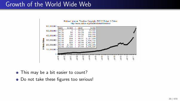
Growth of the World Wide Web
This may be a bit easier to count?
Do not take these figures too serious!
20 / 470
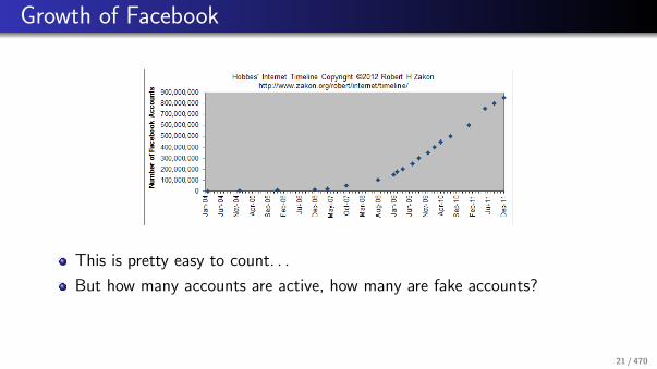
Growth of Facebook
This is pretty easy to count. . .
But how many accounts are active, how many are fake accounts?
21 / 470

Internet Exchange Points (Fall 2013)
Internet Exchange Frankfurt/Germany (DE-CIX)
Connected networks: ≈ 500Average throughput (1 year): ≈ 1.4TbpsMaximum throughput (1 year): ≈ 2.5TbpsMaximum capacity: ≈ 7Tbps200+ Gigabit-Ethernet ports700+ 10Gigabit-Ethernet portshttp://www.decix.de/
Amsterdam Internet Exchange (AMS-IX)
http://www.ams-ix.net/
London Internet Exchange (LINX)
https://www.linx.net/
22 / 470

DE-CIX Traffic (5 Years)
23 / 470

Networking Challenges
Switching efficiency and energy efficiency
Routing and fast convergence
Security, trust, and key management
Network measurements and network operations
Ad-hoc networks and self-organizing networks
Wireless sensor networks and the Internet of Things
Delay and disruption tolerant networks
High bandwidth and long delay networks
Home networks and data center networks
. . .
24 / 470

Internet Programming with Sockets
1 Internet Concepts and Design Principles
2 Structure and Growth of the Internet
3 Internet Programming with Sockets
4 Packet Capturing
25 / 470

Internet Programming with Sockets
Sockets are abstract communication endpoints with a rather small numberof associated function calls
The socket API consists of
address formats for various network protocol familiesfunctions to create, name, connect, destroy socketsfunctions to send and receive datafunctions to convert human readable names to addresses and vice versafunctions to multiplex I/O on several sockets
Sockets are the de-facto standard communication API provided by operatingsystems
26 / 470

Socket Types
Stream sockets (SOCK STREAM) represent bidirectional reliablecommunication endpoints
Datagram sockets (SOCK DGRAM) represent bidirectional unreliablecommunication endpoints
Raw sockets (SOCK RAW) represent endpoints which can send/receiveinterface layer datagrams
Reliable delivered message sockets (SOCK RDM) are datagram sockets withreliable datagram delivery
Sequenced packet sockets (SOCK SEQPACKET) are stream sockets whichretain data block boundaries
27 / 470

IPv4 Socket Addresses
#include <sys/socket.h>
#include <netinet/in.h>
typedef ... sa_family_t;
typedef ... in_port_t;
struct in_addr {
uint8_t s_addr[4]; /* IPv4 address */
};
struct sockaddr_in {
uint8_t sin_len; /* address length (BSD) */
sa_family_t sin_family; /* address family */
in_port_t sin_port; /* transport layer port */
struct in_addr sin_addr; /* IPv4 address */
};
28 / 470
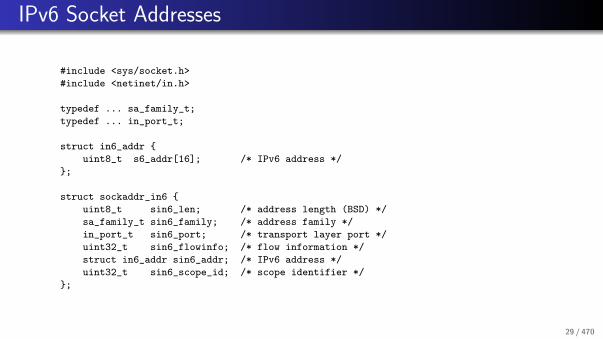
IPv6 Socket Addresses
#include <sys/socket.h>
#include <netinet/in.h>
typedef ... sa_family_t;
typedef ... in_port_t;
struct in6_addr {
uint8_t s6_addr[16]; /* IPv6 address */
};
struct sockaddr_in6 {
uint8_t sin6_len; /* address length (BSD) */
sa_family_t sin6_family; /* address family */
in_port_t sin6_port; /* transport layer port */
uint32_t sin6_flowinfo; /* flow information */
struct in6_addr sin6_addr; /* IPv6 address */
uint32_t sin6_scope_id; /* scope identifier */
};
29 / 470

Connection-Less Communication
data
data
close()
socket()
recvfrom()
sendto()
sendto()
recvfrom()
socket()
bind()
bind()
30 / 470

Connection-Oriented Communication
bind()
listen()
accept()
data
connect()
write()
read()data
connection release
read()
write()
close() close()
socket()
socket()
connection setup
31 / 470

Socket API Summary
#include <sys/types.h>
#include <sys/socket.h>
#include <unistd.h>
#define SOCK_STREAM ...
#define SOCK_DGRAM ...
#define SCOK_RAW ...
#define SOCK_RDM ...
#define SOCK_SEQPACKET ...
#define AF_LOCAL ...
#define AF_INET ...
#define AF_INET6 ...
#define PF_LOCAL ...
#define PF_INET ...
#define PF_INET6 ...
32 / 470
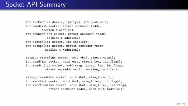
Socket API Summary
int socket(int domain, int type, int protocol);
int bind(int socket, struct sockaddr *addr,
socklen_t addrlen);
int connect(int socket, struct sockaddr *addr,
socklen_t addrlen);
int listen(int socket, int backlog);
int accept(int socket, struct sockaddr *addr,
socklen_t *addrlen);
ssize_t write(int socket, void *buf, size_t count);
int send(int socket, void *msg, size_t len, int flags);
int sendto(int socket, void *msg, size_t len, int flags,
struct sockaddr *addr, socklen_t addrlen);
ssize_t read(int socket, void *buf, size_t count);
int recv(int socket, void *buf, size_t len, int flags);
int recvfrom(int socket, void *buf, size_t len, int flags,
struct sockaddr *addr, socklen_t *addrlen);
33 / 470

Socket API Summary
int shutdown(int socket, int how);
int close(int socket);
int getsockopt(int socket, int level, int optname,
void *optval, socklen_t *optlen);
int setsockopt(int socket, int level, int optname,
void *optval, socklen_t optlen);
int getsockname(int socket, struct sockaddr *addr,
socklen_t *addrlen);
int getpeername(int socket, struct sockaddr *addr,
socklen_t *addrlen);
All API functions operate on abstract socket addresses
Not all functions make equally sense for all socket types
34 / 470

Mapping Names to Addresses
#include <sys/types.h>
#include <sys/socket.h>
#include <netdb.h>
#define AI_PASSIVE ...
#define AI_CANONNAME ...
#define AI_NUMERICHOST ...
struct addrinfo {
int ai_flags;
int ai_family;
int ai_socktype;
int ai_protocol;
size_t ai_addrlen;
struct sockaddr *ai_addr;
char *ai_canonname;
struct addrinfo *ai_next;
};
35 / 470
Mapping Names to Addresses
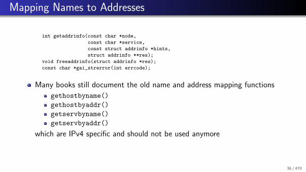
int getaddrinfo(const char *node,
const char *service,
const struct addrinfo *hints,
struct addrinfo **res);
void freeaddrinfo(struct addrinfo *res);
const char *gai_strerror(int errcode);
Many books still document the old name and address mapping functions
gethostbyname()
gethostbyaddr()
getservbyname()
getservbyaddr()
which are IPv4 specific and should not be used anymore
36 / 470
Mapping Addresses to Names
#include <sys/types.h>
#include <sys/socket.h>
#include <netdb.h>
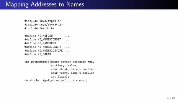
#define NI_NOFQDN ...
#define NI_NUMERICHOST ...
#define NI_NAMEREQD ...
#define NI_NUMERICSERV ...
#define NI_NUMERICSCOPE ...
#define NI_DGRAM ...
int getnameinfo(const struct sockaddr *sa,
socklen_t salen,
char *host, size_t hostlen,
char *serv, size_t servlen,
int flags);
const char *gai_strerror(int errcode);
37 / 470
Multiplexing
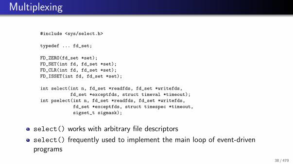
#include <sys/select.h>
typedef ... fd_set;
FD_ZERO(fd_set *set);
FD_SET(int fd, fd_set *set);
FD_CLR(int fd, fd_set *set);
FD_ISSET(int fd, fd_set *set);
int select(int n, fd_set *readfds, fd_set *writefds,
fd_set *exceptfds, struct timeval *timeout);
int pselect(int n, fd_set *readfds, fd_set *writefds,
fd_set *exceptfds, struct timespec *timeout,
sigset_t sigmask);
select() works with arbitrary file descriptors
select() frequently used to implement the main loop of event-drivenprograms
38 / 470

References
B. Carpenter.
Architectural Principles of the Internet.RFC 1958, IAB, June 1996.
B. Carpenter.
Internet Transparency.RFC 2775, IBM, February 2000.
R. Gilligan, S. Thomson, J. Bound, J. McCann, and W. Stevens.
Basic Socket Interface Extensions for IPv6.RFC 3493, Intransa Inc., Cisco, Hewlett-Packard, February 2003.
R. Atkinson and S. Floyd.
IAB Concerns and Recommendations Regarding Internet Research and Evolution.RFC 3869, Internet Architecture Board, August 2004.
S. Kawamura and M. Kawashima.
A Recommendation for IPv6 Address Text Representation.RFC 5952, NEC BIGLOBE, Ltd., NEC AccessTechnica, Ltd., August 2010.
39 / 470

Packet Capturing
1 Internet Concepts and Design Principles
2 Structure and Growth of the Internet
3 Internet Programming with Sockets
4 Packet Capturing
40 / 470

Linux Network Stack Overview
ip
WiFi / WLAN
IEEE 802.3
Ethernet
Tun/Tap
tcpdump firefox arping openvpn
AF
_N
ET
LIN
K
AF
_IN
ET
AF
_P
AC
KE
T
SO
CK
_R
AW
SO
CK
_R
AW
SO
CK
_R
AW
BPF
MACebtables
iptables
traceroute
IEEE 802.11
transportUDP
TCP
networkIPv4
IPv6
data linkLLC
user space
libpcap
kernel space
socket socket
driver driver
driver
socket socket /dev/.../dev/...
41 / 470

Motivation and Requirements
Network protocol analyzers like wireshark, tcpdump or ngrep running inuser space want to receive (raw) packets as they are received by the devicedrivers in the kernel.
User space tools like iftop, ntop, yaf, softflowd, vnstat want toreceive (raw) packets in order to produce statistics.
To achieve a solution with good performance,
captured packets should be filtered or aggregated as early as possible,copying of packets should be avoided as much as possible since copying datais an expensive operation, andthe number of system calls and associated context switches should beminimized
⇒ Discard unimportant packets (frames) as early as possible
42 / 470

BSD Packet Filter (BPF)
The BSD Packet Filter is based on a simple but powerful control-flowmachine, which is implemented in the kernel.
A BPF program is generated by user space applications and sent to thekernel for execution.
Human readable filter expressions are translated into BPF programs using acompiler.
Packets that pass a BPF filter are first collected within the kernel and latermoved to user space applications in batches.
The BPF machine has the following components:
An accumulator for all calculationsAn index register (x) allowing access to data relative to a certain positionMemory for storing intermediate results
All registers and memory locations of the BPF are 32-bit wide.
43 / 470

BPF within a Unix Kernel
link−leveldriver
link−leveldriver
link−leveldriver
buffer
filter
buffer
filter
buffer
filter
stack
protocol
user
kernel
kernel
network
BPF
44 / 470

BPF Example #1
Select all Ethernet frames which contain IPv4 packets:
(000) ldh [12] ; load ethernet type field
(001) jeq #0x800 jt 2 jf 3 ; compare with 0x800
(002) ret #96 ; return snaplen
(003) ret #0 ; filter failed
45 / 470

BPF Example #2
Select all Ethernet frames which contain IPv4 packets which do notoriginate are not from the networks 128.3.112/24 and 128.3.254/24 (ipand not src net 128.3.112/24 and not src net 128.3.254/24):
(000) ldh [12] ; load ethernet type field
(001) jeq #0x800 jt 2 jf 7 ; compare with 0x800
(002) ld [26] ; load ipv4 address field
(003) and #0xffffff00 ; mask the network part
(004) jeq #0x80037000 jt 7 jf 5 ; compare with 128.3.112.0
(005) jeq #0x8003fe00 jt 7 jf 6 ; compare with 128.3.254.0
(006) ret #96 ; return snaplen
(007) ret #0 ; filter failed
46 / 470

libpcap
The libpcap C library provides the following functionality:
portable API that hides the differences of packet filter implementations indifferent operating systems.A compiler which translates human readable filter expressions into BPFprograms.An interpreter for BPF programs which can be used to filter (previouslycaptured) packets in user space.Functions for writing captured packets to files and for reading previouslycaptured packets from files.
47 / 470

References
S. McCanne and V. Jacobson.
The BSD Packet Filter: A New Architecture for User-level Packet Capture.In Proc. Usenix Winter Conference, January 1993.
48 / 470

Part: Local Area Networks (IEEE 802)
5 Local Area Networks Overview
6 IEEE 802.3 (Ethernet)
7 IEEE 802.1 Bridges
8 IEEE 802.1Q Virtual LANs
9 IEEE 802.1X Port Access Control
10 IEEE 802.11 Wireless LAN
49 / 470

Local Area Networks Overview
5 Local Area Networks Overview
6 IEEE 802.3 (Ethernet)
7 IEEE 802.1 Bridges
8 IEEE 802.1Q Virtual LANs
9 IEEE 802.1X Port Access Control
10 IEEE 802.11 Wireless LAN
50 / 470

IEEE 802 Overview
802 O
verv
iew
an
d A
rch
itectu
re
Physical802.6
802.6MediumAccess
DQDB
Physical802.5
Token Ring
802.5MediumAccess
Physical802.4
Token Bus
802.4MediumAccess
Physical802.3
Ethernet
Medium802.3
Access
Physical802.11
WLAN
802.11MediumAccess
WiMAX
802.16Physical
802.16MediumAccess
Physical802.14
MediumAccess
802.15
Bluetooth
WPAN
802.1 Bridging
802.2 Logical Link Control
802.1
Man
ag
em
en
t
IEEE 802 standards are developed since the mid 1980s
Dominating technology in local area networks (LANs)
51 / 470

IEEE 802 Layers in the OSI Model
End−System
Physical
Data Link
Transport
Application
Network
Application S
ystemT
ransport System
Physical (PHY)
Media Access Control (MAC)
Logical Link Control (LLC)
IEE
E 802
Representation
Session
Application Process
The Logical Link Controllayer provides a commonservice interface for all IEEE802 protocols
The Medium Access Controllayer defines the method usedto access the transmissionmedia used
The Physical layer defines thephysical properties for thevarious transmission mediathat can be used with acertain IEEE 802.x protocol
52 / 470

IEEE 802 Addresses
IEEE 802 addresses (sometimes called MAC addresses or meanwhile alsoEUI-48 addresses) are 6 octets (48 bit) long
The common notation is a sequence of hexadecimal numbers with the bytesseparated from each other using colons or hyphens (00:D0:59:5C:03:8A or00-D0-59-5C-03-8A)
The highest bit indicates whether it is a unicast address (0) or a multicastaddress (1). The second highest bit indicates whether it is a local (1) or aglobal (0) address
The broadcast address, which represents all stations within a broadcastdomain, is FF-FF-FF-FF-FF-FF
Globally unique addresses are created by vendors who apply for a numberspace delegation by the IEEE
53 / 470

IEEE 802.3 (Ethernet)
5 Local Area Networks Overview
6 IEEE 802.3 (Ethernet)
7 IEEE 802.1 Bridges
8 IEEE 802.1Q Virtual LANs
9 IEEE 802.1X Port Access Control
10 IEEE 802.11 Wireless LAN
54 / 470

IEEE 802.3 (Ethernet)
Evolution of Ethernet Technology:1976 Original Ethernet paper published1990 10 Mbps Ethernet over twisted pair (10BaseT)1995 100 Mbps Ethernet1998 1 Gbps Ethernet2002 10 Gbps Ethernet2010 100 Gbps Ethernet2015 1 Tbps Ethernet (predicted)2020 100 Tbps Ethernet (predicted)
Link aggregation allows to “bundle” links, e.g., four 10 Gbps links can bebundled to perform like a single 40 Gbps link
55 / 470

IEEE 802.3 Frame Format
start−of−frame delimiter (SFD)
destination MAC address
source MAC address
length / type field
preamble
data
frame check sequence (FCS)
(network layer packet)
1 Byte
7 Byte
6 Byte
6 Byte
2 Byte
46−1500 Byte
4 Byte
padding (if required)
64−1
518
Byt
e
Classic Ethernet used CSMA/CDand a shared bus
Today’s Ethernet uses a startopology with full duplex links
Jumbo frames with sizes up to 9000bytes can be used on dedicatedlinks to improve throughput
Interface cards capable to segmentlarge chunks of data (e.g., 64k)into a sequence of frames (largesegment offload, LSO) improvethroughput on the sending side
56 / 470

Transmitting and Receiving IEEE 802.3 Frames (CSMA/CD)
wait for frame to transmit
format frame for transmission
carrier sense signal on?
wait interframe gap time
start transmission
collision detected?
complete transmission andset status transmission done
set status attempt limit exceeded
transmit jam sequence andincrement # attempts
attempt limit reached?
compute and wait backoff time
YN
N
N
Y
Y
incoming signal detected?
set carrier sense signal on
obtain bit sync and wait for SFD
receive frame
FCS and frame size OK?
destination address matchesown or group address?
pass data to higher-layerprotocol entity for processing
discard frame
N
N
N
Y
Y
Y
57 / 470
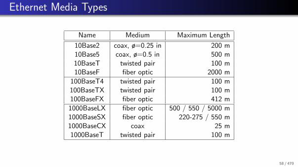
Ethernet Media Types
Name Medium Maximum Length
10Base2 coax, ø=0.25 in 200 m10Base5 coax, ø=0.5 in 500 m10BaseT twisted pair 100 m10BaseF fiber optic 2000 m
100BaseT4 twisted pair 100 m100BaseTX twisted pair 100 m100BaseFX fiber optic 412 m
1000BaseLX fiber optic 500 / 550 / 5000 m1000BaseSX fiber optic 220-275 / 550 m1000BaseCX coax 25 m1000BaseT twisted pair 100 m
58 / 470
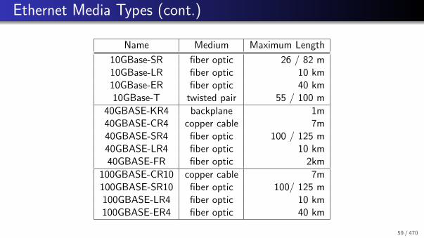
Ethernet Media Types (cont.)
Name Medium Maximum Length
10GBase-SR fiber optic 26 / 82 m10GBase-LR fiber optic 10 km10GBase-ER fiber optic 40 km10GBase-T twisted pair 55 / 100 m
40GBASE-KR4 backplane 1m40GBASE-CR4 copper cable 7m40GBASE-SR4 fiber optic 100 / 125 m40GBASE-LR4 fiber optic 10 km40GBASE-FR fiber optic 2km
100GBASE-CR10 copper cable 7m100GBASE-SR10 fiber optic 100/ 125 m100GBASE-LR4 fiber optic 10 km100GBASE-ER4 fiber optic 40 km
59 / 470

IEEE 802.1 Bridges
5 Local Area Networks Overview
6 IEEE 802.3 (Ethernet)
7 IEEE 802.1 Bridges
8 IEEE 802.1Q Virtual LANs
9 IEEE 802.1X Port Access Control
10 IEEE 802.11 Wireless LAN
60 / 470

Bridged IEEE 802 Networks
B1
B2
10Base2
10Base2
10Base5
100BaseT
B3
802.11
802.5
61 / 470

IEEE 802 Bridges
IEEE 802.3 PHY
IEEE 802.3 MAC
Network
IEEE 802.2 LLC
IEEE 802.3 MAC
IEEE 802.11 PHY
IEEE 802.11 MAC
IEEE 802.3 PHY
IEEE 802.2 LLC
Bridge
IEEE 802.11 PHY
IEEE 802.11 MAC
Network
IEEE 802.2 LLC
Source Routing Bridges: Sender has to route the frame through the bridgednetwork
Transparent Bridges: Bridges are transparent to senders and receivers
62 / 470

Transparent Bridges (IEEE 802.1D)
Station Portnumberaddress
Forwardingdatabase
Bridge
protocol
entity
Port
management
software
MACchipset
Memorybuffers
MACchipset
Port 1 Port 2
Lookup an entry with a matching destination address in the forwardingdatabase and forward the frame to the associated port.
If no matching entry exists, forward the frame to all outgoing ports exceptthe port from which the frame was received (flooding).
63 / 470

Backward Learning
Algorithm:
The forwarding database is initially empty.Whenever a frame is received, add an entry to the forwarding database (if itdoes not yet exist) using the frame’s source address and the incoming portnumber.Reinitialize the timer attached to the forwarding base entry for the receivedframe.
Aging of unsused entries reduces forwarding table size and allows bridges toadapt to topology changes.
Backward learning requires an cycle free topology.
64 / 470
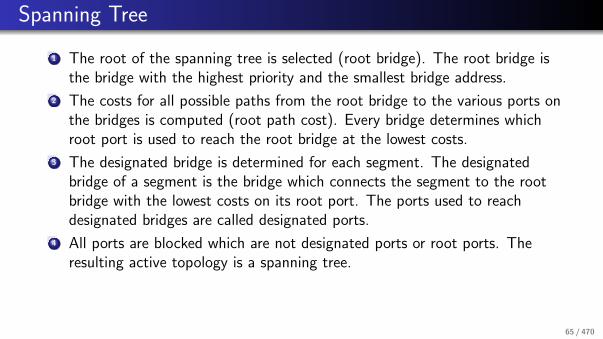
Spanning Tree
1 The root of the spanning tree is selected (root bridge). The root bridge isthe bridge with the highest priority and the smallest bridge address.
2 The costs for all possible paths from the root bridge to the various ports onthe bridges is computed (root path cost). Every bridge determines whichroot port is used to reach the root bridge at the lowest costs.
3 The designated bridge is determined for each segment. The designatedbridge of a segment is the bridge which connects the segment to the rootbridge with the lowest costs on its root port. The ports used to reachdesignated bridges are called designated ports.
4 All ports are blocked which are not designated ports or root ports. Theresulting active topology is a spanning tree.
65 / 470

Port States
Blocking: A port in the blocking state does not participate in frameforwarding.
Listening: A port in the transitional listening state has been selected by thespanning tree protocol to participate in fame forwarding.
Learning: A port in the transitional learning state is preparing to participatein frame forwarding.
Forwarding: A port in the forwarding state forwards frames.
Disabled: A port in the disabled state does not participate in frameforwarding or the operation of spanning tree protocol.
66 / 470

Port State Transitions
Blocking
Listening
Forwarding
Learning
Disabled
67 / 470

Broadcast Domains
A bridged LAN defines a single broadcast domain:
All frames send to the broadcast address are forwarded on all links in thebridged networks.Broadcast traffic can take a significant portion of the available bandwidth.Devices running not well-behaving applications can cause broadcast storms.Bridges may flood frames if the MAC address cannot be found in theforwarding table.
It is desirable to reduce the size of broadcast domains in order to separatetraffic in a large bridged LAN.
68 / 470

IEEE 802.1Q Virtual LANs
5 Local Area Networks Overview
6 IEEE 802.3 (Ethernet)
7 IEEE 802.1 Bridges
8 IEEE 802.1Q Virtual LANs
9 IEEE 802.1X Port Access Control
10 IEEE 802.11 Wireless LAN
69 / 470

IEEE 802.1Q Virtual LANs
VLANs allow to separate the traffic on an IEEE 802 network
A station connected to a certain VLAN only sees frames belonging to thatVLAN
VLANs can reduce the network load; frames that are targeted to all stations(broadcasts) will only be delivered to the stations connected to the VLAN.
Stations (especially server) can be a member of multiple VLANssimultaneously
Separation of logical LAN topologies from physical LAN topologies
VLANs are identified by a VLAN identifier (1..4094)
70 / 470

IEEE 802.1Q Tagged Frames
start−of−frame delimiter (SFD)
destination MAC address
source MAC address
preamble
1 Byte
7 Byte
6 Byte
6 Byte
length / type field
data
frame check sequence (FCS)
(network layer packet)
2 Byte
46−1500 Byte
4 Byte
padding (if required)
2 Bytetag protocol identifier
vlan identifierpriority CF
I
64−1
522
Byt
e
The tag protocol identifierindicates a tagged frame
Tagged 802.3 frames are 4bytes longer than original802.3 frames
Tagged frames should onlyappear on links that areVLAN aware
71 / 470

VLAN Membership
Bridge ports can be assigned to VLANs in different ways:
Ports are administratively assigned to VLANs (port-based VLANs)MAC addresses are administratively assigned to VLANs (MAC address-basedVLANs)Frames are assigned to VLANs based on the payload contained in the frames(protocol-based VLANs)Members of a certain multicast group are assigned to VLAN (multicastgroup VLANs)
The Generic Attribute Registration Protocol (GARP) can (among otherthings) propagate VLAN membership information.
72 / 470
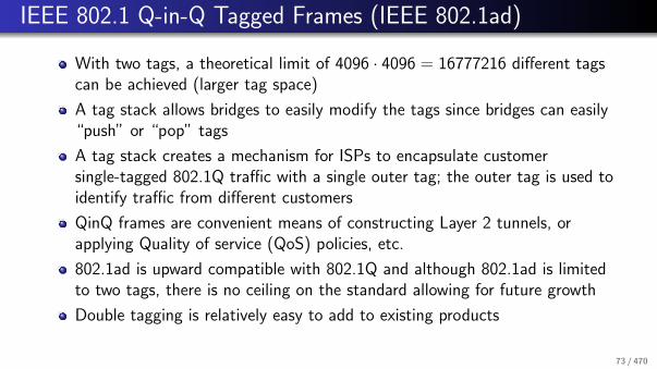
IEEE 802.1 Q-in-Q Tagged Frames (IEEE 802.1ad)
With two tags, a theoretical limit of 4096 · 4096 = 16777216 different tagscan be achieved (larger tag space)
A tag stack allows bridges to easily modify the tags since bridges can easily“push” or “pop” tags
A tag stack creates a mechanism for ISPs to encapsulate customersingle-tagged 802.1Q traffic with a single outer tag; the outer tag is used toidentify traffic from different customers
QinQ frames are convenient means of constructing Layer 2 tunnels, orapplying Quality of service (QoS) policies, etc.
802.1ad is upward compatible with 802.1Q and although 802.1ad is limitedto two tags, there is no ceiling on the standard allowing for future growth
Double tagging is relatively easy to add to existing products
73 / 470

IEEE 802.1X Port Access Control
5 Local Area Networks Overview
6 IEEE 802.3 (Ethernet)
7 IEEE 802.1 Bridges
8 IEEE 802.1Q Virtual LANs
9 IEEE 802.1X Port Access Control
10 IEEE 802.11 Wireless LAN
74 / 470
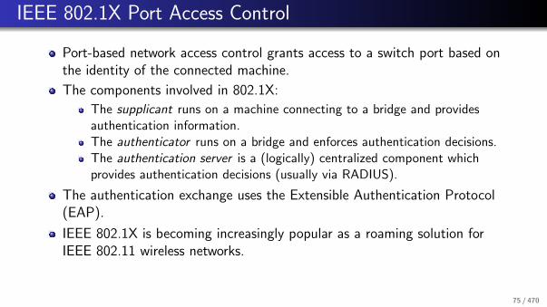
IEEE 802.1X Port Access Control
Port-based network access control grants access to a switch port based onthe identity of the connected machine.
The components involved in 802.1X:
The supplicant runs on a machine connecting to a bridge and providesauthentication information.The authenticator runs on a bridge and enforces authentication decisions.The authentication server is a (logically) centralized component whichprovides authentication decisions (usually via RADIUS).
The authentication exchange uses the Extensible Authentication Protocol(EAP).
IEEE 802.1X is becoming increasingly popular as a roaming solution forIEEE 802.11 wireless networks.
75 / 470

IEEE 802.11 Wireless LAN
5 Local Area Networks Overview
6 IEEE 802.3 (Ethernet)
7 IEEE 802.1 Bridges
8 IEEE 802.1Q Virtual LANs
9 IEEE 802.1X Port Access Control
10 IEEE 802.11 Wireless LAN
76 / 470

IEEE 802.11 Wireless LAN
Protocol Released Frequency Data Rate Indoor Outdoor
802.11a 1999 5 GHz 54 Mbps 35m 120m802.11b 1999 2.4 GHz 11 Mbps 38m 140m802.11g 2003 2.4 GHz 54 Mbps 38m 140m802.11n 2009 2.4/5 GHz 248 Mbps 70m 250m802.11ac 2014 5 GHz 600 Mbps 70m 250m
Very widely used wireless local area network (WLAN).
As a consequence, very cheap equipment (base stations, interface cards).
Wired equivalent privacy (WEP) was a disaster (at least for those whobelieve a wire is secure).
Recommended is WPA-2 (Wifi Protected Access), in particular incombination with 802.1X and EAP-TLS.
77 / 470

IEEE 802.11 2.4 GHz Channels
78 / 470

IEEE 802.11 Frame Types
Data Frames: Carrying “useful” payloads
Control Frames: Facilitate the exchange of data frames
Ready-to-send (RTS) and Clear-to-send (CTS) framesAcknowledgement (ACK) frames
Management Frames: Maintenance of the network
Beacon framesAuthentication / deauthentication framesAssociation / deassociation framesProbe request / response framesReassociation request / response frames
79 / 470

IEEE 802.11 Frame Format
80 / 470

IEEE 802.15.4 (LowPAN)
Low power (battery operated) personal area networks (LowPAN)
Operates in 868-868.8 MHz (Europe), 902-928 MHz (North America),2400-2483.5 MHz (worldwide) frequency bands.
Application areas: Home automation, surveillance systems, logistics, . . .
Full function devices (FFDs) serve as coordinator of a personal area network(PAN).
Reduced function devices (RFDs) are extremely simple and can be batterypowered with long lifetimes.
IEEE 802.15.4a provides localization support.
81 / 470

References
R. M. Metcalfe and D. R. Boggs.
Ethernet: Distributed packet switching for local computer networks.Communications of the ACM, 19(5):395–404, July 1976.
R. Perlman.
An Algorithm for Distributed Computation of a Spanning Tree in an Extended LAN.SIGCOMM Computer Communication Review, 15(4), September 1985.
A. F. Benner, P. K. Pepeljugoski, and R. J. Recio.
A Roadmap to 100G Ethernet at the Enterprise Data Center.IEEE Applications and Practice, 45(3), November 2007.
L. D. Nardis and M.-G. Di Benedetto.
Overview of the IEEE 802.15.4/4a standards for low data rate Wireless Personal Data Networks.In Proc. of the 4th IEEE Workshop on Positioning, Navigation and Communication 2007 (WPNC’07), Hannover, March 2007. IEEE.
82 / 470

Part: Internet Network Layer
11 Internet Network Layer Overview
12 Internet Protocol Version 4IPv4 ForwardingIPv4 Error Handling (ICMPv4)IPv4 FragmentationIPv4 over IEEE 802.3IPv4 Configuration (DHCP)
13 Internet Protocol Version 6
83 / 470

Internet Network Layer Overview
11 Internet Network Layer Overview
12 Internet Protocol Version 4IPv4 ForwardingIPv4 Error Handling (ICMPv4)IPv4 FragmentationIPv4 over IEEE 802.3IPv4 Configuration (DHCP)
13 Internet Protocol Version 6
84 / 470

Internet Model
Media Media
Subnetwork
Internet
Transport
Subnetwork
NetworkInternet
Transport Router
Application
End System
Application ProcessApplication Process
Endsystem
Application
Subnetwork
85 / 470

Terminology
A node is a device which implements an Internet Protocol (such as IPv4 orIPv6).
A router is a node that forwards IP packets not addressed to itself.
A host is any node which is not a router.
A link is a communication channel below the IP layer which allows nodes tocommunicate with each other (e.g., an Ethernet).
The neighbors is the set of all nodes attached to the same link.
86 / 470

Terminology (cont.)
An interface is a node’s attachement to a link.
An IP address identifies an interface or a set of interfaces.
An IP packet is a bit sequence consisting of an IP header and the payload.
The link MTU is the maximum transmission unit, i.e., maximum packet sizein octets, that can be conveyed over a link.
The path MTU is the the minimum link MTU of all the links in a pathbetween a source node and a destination node.
87 / 470

Internet Network Layer Protocols
The Internet Protocol version 4 (IPv4) provides for transmitting datagramsfrom sources to destinations using 4 byte IPv4 addresses
The Internet Control Message Protocol version 4 (ICMPv4) is used for IPv4error reporting and testing
The Address Resolution Protocol (ARP) maps IPv4 addresses to IEEE 802addresses
The Internet Protocol version 6 (IPv6) provides for transmitting datagramsfrom sources to destinations using 16 byte IPv6 addresses
The Internet Control Message Protocol version 6 (ICMPv6) is used for IPv6error reporting, testing, auto-configuration and address resolution
88 / 470

Reserved IPv4 Address Blocks
0.0.0.0/8 ”This” Network [RFC1700]10.0.0.0/8 Private-Use Networks [RFC1918]14.0.0.0/8 Public-Data Networks [RFC1700]24.0.0.0/8 Cable Television Networks [RFC3330]39.0.0.0/8 Class A Subnet Experiment [RFC1797]127.0.0.0/8 Loopback [RFC1700]128.0.0.0/16 Reserved by IANA [RFC3330]169.254.0.0/16 Link Local [RFC3330]172.16.0.0/12 Private-Use Networks [RFC1918]191.255.0.0/16 Reserved by IANA [RFC3330]192.0.0.0/24 Reserved by IANA [RFC3330]192.0.2.0/24 Test-Net / Documentation [RFC3330]192.88.99.0/24 6to4 Relay Anycast [RFC3068]192.168.0.0/16 Private-Use Networks [RFC1918]198.18.0.0/15 Network Interconnect / Device Benchmark Testing [RFC2544]223.255.255.0/24 Reserved by IANA [RFC3330]224.0.0.0/4 Multicast [RFC3171]240.0.0.0/4 Reserved for Future Use [RFC1700]
89 / 470

Internet Protocol Version 4
11 Internet Network Layer Overview
12 Internet Protocol Version 4IPv4 ForwardingIPv4 Error Handling (ICMPv4)IPv4 FragmentationIPv4 over IEEE 802.3IPv4 Configuration (DHCP)
13 Internet Protocol Version 6
90 / 470

IPv4 Packet Format
0 1 2 3
0 1 2 3 4 5 6 7 8 9 0 1 2 3 4 5 6 7 8 9 0 1 2 3 4 5 6 7 8 9 0 1
+-+-+-+-+-+-+-+-+-+-+-+-+-+-+-+-+-+-+-+-+-+-+-+-+-+-+-+-+-+-+-+-+
|Version| IHL |Type of Service| Total Length |
+-+-+-+-+-+-+-+-+-+-+-+-+-+-+-+-+-+-+-+-+-+-+-+-+-+-+-+-+-+-+-+-+
| Identification |Flags| Fragment Offset |
+-+-+-+-+-+-+-+-+-+-+-+-+-+-+-+-+-+-+-+-+-+-+-+-+-+-+-+-+-+-+-+-+
| Time to Live | Protocol | Header Checksum |
+-+-+-+-+-+-+-+-+-+-+-+-+-+-+-+-+-+-+-+-+-+-+-+-+-+-+-+-+-+-+-+-+
| Source Address |
+-+-+-+-+-+-+-+-+-+-+-+-+-+-+-+-+-+-+-+-+-+-+-+-+-+-+-+-+-+-+-+-+
| Destination Address |
+-+-+-+-+-+-+-+-+-+-+-+-+-+-+-+-+-+-+-+-+-+-+-+-+-+-+-+-+-+-+-+-+
| Options | Padding |
+-+-+-+-+-+-+-+-+-+-+-+-+-+-+-+-+-+-+-+-+-+-+-+-+-+-+-+-+-+-+-+-+
91 / 470

IPv4 Forwarding
IPv4 addresses can be devided into a part which identifies a network (netid)and a part which identifies an interface of a node within that network(hostid).
The number of bits of an IPv4 address which identifies the network is calledthe address prefix.
The address prefix is commonly written as a decimal number, appended tothe usual IPv4 address notation by using a slash (/) as a separator (e.g.,192.0.2.0/24).
The forwarding table realizes a mapping of the network prefix to the nextnode (next hop) and the local interface used to reach the next node.
For every IP packet, the entry in the forwarding table has to be found withlongest matching network address prefix (longest prefix match).
92 / 470

IPv4 Forwarding Example
192.0.2.2
H1
192.0.2.65
R2
192.0.2.10
192.0.2.64/26
192.0.2.1
Next Hop Interface
eth0
H2
192.0.2.70
R1
Prefix
0.0.0.0/0192.0.2.2 eth0192.0.2.65 eth1
192.0.2.0/24192.0.2.64/26
192.0.2.0/24192.0.2.64/260.0.0.0/0
Prefix
0.0.0.0/0
Prefix
192.0.2.64/26192.0.2.65
Next Hop
192.0.2.70
Interface
eth0eth0
Interface
eth0eth0eth0
Next Hop
192.0.2.1192.0.2.2192.0.2.10
192.0.2.1
192.0.2.0/24
Default forwarding table entries use the prefix 0.0.0.0/0.
This example identifies directly reachable hosts by using the IP address of alocal interface as the next hop.
Other representations use an explicit direct/indirect flag.
93 / 470

Longest Prefix Match: Binary Trie
0 1
H
0 01 1
C D C
B
B
G
F
D
E
1
1
11
0
0
0
0
0
0
A
D J
CD
G
G
0
0
0
0
0
0
0
0
1
1 1
1
1 0
A binary trie is the representation of the binary prefixes in a tree.
94 / 470

Longest Prefix Match: Path Compressed Trie
0 1
H
0 01 1
C D C
B
B G
F
D E
1
1 1
1
0
0
0
0
A
D J
C
D
G
G
0 0
0 0
0
1
1 1
1
1
2
3 3
2
3
4 4 4 5
5 5
A path compressed trie is obtained by collapsing all one-way branch nodes.The number attached to nodes indicates the next (absolute) bit to inspect.While walking down the tree, you verify in each step that the prefix stillmatches the prefix stored at each node.The figure is likely WRONG and there needs to be an EXAMPLE.
95 / 470

Longest Prefix Match: Two-bit stride multibit Trie
00 10
H
01 11
C D C
B F
B E
D JAA
D
00
00
00 1001 11
G G
01
D
00 01
G C C
01 10 11
00 01 10
G D D
100100
B
00 01 10
A two-bit multibit trie reduces the number of memory accesses.
96 / 470

IPv4 Error Handling (ICMPv4)
The Internet Control Message Protocol (ICMP) is used to inform nodesabout problems encountered while forwarding IP packets.
Echo Request/Reply messages are used to test connectivity.Unreachable Destination messages are used to report why a destination isnot reachable.Redirect messages are used to inform the sender of a better (shorter) path.
Can be used to trace routes to hosts:
Send messages with increasing TTL starting with one and interpret theICMP response message.Pack additional data into the request to measure latency.
ICMPv4 is an integral part of IPv4 (even though it is a different protocol).
97 / 470

ICMPv4 Echo Request/Reply
0 1 2 3
0 1 2 3 4 5 6 7 8 9 0 1 2 3 4 5 6 7 8 9 0 1 2 3 4 5 6 7 8 9 0 1
+-+-+-+-+-+-+-+-+-+-+-+-+-+-+-+-+-+-+-+-+-+-+-+-+-+-+-+-+-+-+-+-+
| Type | Code | Checksum |
+-+-+-+-+-+-+-+-+-+-+-+-+-+-+-+-+-+-+-+-+-+-+-+-+-+-+-+-+-+-+-+-+
| Identifier | Sequence Number |
+-+-+-+-+-+-+-+-+-+-+-+-+-+-+-+-+-+-+-+-+-+-+-+-+-+-+-+-+-+-+-+-+
| Data ...
+-+-+-+-+-
The ICMP echo request message (type = 8, code = 0) asks the destinationnode to return an echo reply message (type = 0, code = 0).
The Identifier and Sequence Number fields are used to correlateincoming replies with outstanding requests.
The data field may contain any additional data.
98 / 470

ICMPv4 Unreachable Destinations
0 1 2 3
0 1 2 3 4 5 6 7 8 9 0 1 2 3 4 5 6 7 8 9 0 1 2 3 4 5 6 7 8 9 0 1
+-+-+-+-+-+-+-+-+-+-+-+-+-+-+-+-+-+-+-+-+-+-+-+-+-+-+-+-+-+-+-+-+
| Type | Code | Checksum |
+-+-+-+-+-+-+-+-+-+-+-+-+-+-+-+-+-+-+-+-+-+-+-+-+-+-+-+-+-+-+-+-+
| unused |
+-+-+-+-+-+-+-+-+-+-+-+-+-+-+-+-+-+-+-+-+-+-+-+-+-+-+-+-+-+-+-+-+
| Internet Header + 64 bits of Original Data Datagram |
+-+-+-+-+-+-+-+-+-+-+-+-+-+-+-+-+-+-+-+-+-+-+-+-+-+-+-+-+-+-+-+-+
The Type field has the value 3 for all unreachable destination messages.
The Code field indicates why a certain destination is not reachable.
The data field contains the beginning of the packet which caused the ICMPunreachable destination message.
99 / 470

Unreachable Destination Codes
0 Net Unreachable1 Host Unreachable2 Protocol Unreachable3 Port Unreachable4 Fragmentation Needed and Don’t Fragment was Set5 Source Route Failed6 Destination Network Unknown7 Destination Host Unknown8 Source Host Isolated9 Communication with Destination Network is Administratively Prohibited10 Communication with Destination Host is Administratively Prohibited11 Destination Network Unreachable for Type of Service12 Destination Host Unreachable for Type of Service13 Communication Administratively Prohibited14 Host Precedence Violation15 Precedence cutoff in effect
100 / 470

ICMPv4 Redirect
0 1 2 3
0 1 2 3 4 5 6 7 8 9 0 1 2 3 4 5 6 7 8 9 0 1 2 3 4 5 6 7 8 9 0 1
+-+-+-+-+-+-+-+-+-+-+-+-+-+-+-+-+-+-+-+-+-+-+-+-+-+-+-+-+-+-+-+-+
| Type | Code | Checksum |
+-+-+-+-+-+-+-+-+-+-+-+-+-+-+-+-+-+-+-+-+-+-+-+-+-+-+-+-+-+-+-+-+
| Router Internet Address |
+-+-+-+-+-+-+-+-+-+-+-+-+-+-+-+-+-+-+-+-+-+-+-+-+-+-+-+-+-+-+-+-+
| Internet Header + 64 bits of Original Data Datagram |
+-+-+-+-+-+-+-+-+-+-+-+-+-+-+-+-+-+-+-+-+-+-+-+-+-+-+-+-+-+-+-+-+
The Type field has the value 5 for redirect messages.
The Code field indicates which type of packets should be redirected.
The Router Internet Address field identifies the IP router to whichpackets should be redirected.
The data field contains the beginning of the packet which caused the ICMPredirect message.
101 / 470

Redirect Codes
0 Redirect datagrams for the Network.1 Redirect datagrams for the Host.2 Redirect datagrams for the Type of Service and Network.3 Redirect datagrams for the Type of Service and Host.
102 / 470

IPv4 Fragmentation
IPv4 packets that do not fit the outgoing link MTU will get fragmented intosmaller packets that fit the link MTU.
The Identification field contains the same value for all fragments of anIPv4 packet.The Fragment Offset field contains the relative position of a fragment ofan IPv4 packet (counted in 64-bit words).The flag More Fragments (MF) is set if more fragments follow.
The Don’t Fragment (DF) flag can be set to indicate that a packet shouldnot be fragmented.
IPv4 allows fragments to be further fragmented without intermediatereassembly.
103 / 470

Fragmentation Considered Harmful
The receiver must buffer fragments until all fragments have been received.However, it is not useful to keep fragments in a buffer indefinitely. Hence,the TTL field of all buffered packets will be decremented once per secondand fragments are dropped when the TTL field becomes zero.
The loss of a fragment causes in most cases the sender to resend theoriginal IP packet which in most cases gets fragmented as well. Hence, theprobability of transmitting a large IP packet successfully goes quickly downif the loss rate of the network goes up.
Since the Identification field identifies fragments that belong togetherand the number space is limited, one cannot fragment an arbitrary largenumber of packets.
104 / 470

MTU Path Discovery (RFC 1191)
The sender sends IPv4 packets with the DF flag set.
A router which has to fragment a packet with the DF flag turned on dropsthe packet and sends an ICMP message back to the sender which alsoincludes the local maximum link MTU.
Upon receiving the ICMP message, the sender adapts his estimate of thepath MTU and retries.
Since the path MTU can change dynamically (since the path can change), aonce learned path MTU should be verified and adjusted periodically.
Not all routers send necessarily the local link MTU. In this cases, the sendertries typical MTU values, which is usually faster than doing a binary search.
105 / 470

IPv4 over IEEE 802.3 (RFC 894)
IPv4 packets are sent in the payload of IEEE 802.3 frames according to thespecification in RFC 894:
IPv4 packets are identified by the value 0x800 in the IEEE 802.3 type field.According to the maximum length of IEEE 802.3 frames, the maximum linkMTU is 1500 byte.The mapping of IPv4 addresses to IEEE 802.3 addresses is table driven.Entries in so called mapping tables (sometimes also called addresstranslation tables) can either be statically configured or dynamically learned.
Note that the RFC 894 approach does not provide an assurance that themapping is actually correct...
106 / 470

IPv4 Address Translation (RFC 826)
0 1 2 3
0 1 2 3 4 5 6 7 8 9 0 1 2 3 4 5 6 7 8 9 0 1 2 3 4 5 6 7 8 9 0 1
+-+-+-+-+-+-+-+-+-+-+-+-+-+-+-+-+-+-+-+-+-+-+-+-+-+-+-+-+-+-+-+-+
| Hardware Type | Protocol Type |
+-+-+-+-+-+-+-+-+-+-+-+-+-+-+-+-+-+-+-+-+-+-+-+-+-+-+-+-+-+-+-+-+
| HLEN | PLEN | Operation |
+-+-+-+-+-+-+-+-+-+-+-+-+-+-+-+-+-+-+-+-+-+-+-+-+-+-+-+-+-+-+-+-+
| Sender Hardware Address (SHA) =
+-+-+-+-+-+-+-+-+-+-+-+-+-+-+-+-+-+-+-+-+-+-+-+-+-+-+-+-+-+-+-+-+
= Sender Hardware Address (SHA) | Sender IP Address (SIP) =
+-+-+-+-+-+-+-+-+-+-+-+-+-+-+-+-+-+-+-+-+-+-+-+-+-+-+-+-+-+-+-+-+
= Sender IP Address (SIP) | Target Hardware Address (THA) =
+-+-+-+-+-+-+-+-+-+-+-+-+-+-+-+-+-+-+-+-+-+-+-+-+-+-+-+-+-+-+-+-+
= Target Hardware Address (THA) |
+-+-+-+-+-+-+-+-+-+-+-+-+-+-+-+-+-+-+-+-+-+-+-+-+-+-+-+-+-+-+-+-+
| Target IP Address |
+-+-+-+-+-+-+-+-+-+-+-+-+-+-+-+-+-+-+-+-+-+-+-+-+-+-+-+-+-+-+-+-+
The Address Resolution Protocol (ARP) resolved IPv4 addresses tolink-layer addresses of neighboring nodes.
107 / 470

ARP and RARP
The Hardware Type field identifies the address type used on the link-layer(the value 1 is used for IEEE 802.3 MAC addresses).
The Protocol Type field identifies the network layer address type (thevalue 0x800 is used for IPv4).
ARP/RARP packets use the 802.3 type value 0x806.
The Operation field contains the message type: ARP Request (1), ARPResponse (2), RARP Request (3), RARP Response (4).
The sender fills, depending on the request type, either the Target IP
Address field (ARP) or the Target Hardware Address field (RARP).
The responding node swaps the Sender/Target fields and fills the emptyfields with the requested information.
108 / 470

DHCP Version 4 (DHCPv4)
The Dynamic Host Configuration Protocol (DHCP) allows nodes to retrieveconfiguration parameters from a central configuration server.
A binding is a collection of configuration parameters, including at least an IPaddress, associated with or bound to a DHCP client.
Bindings are managed by DHCP servers.
Bindings are typically valid only for a limited lifetime.
See RFC 2131 for the details and the message formats.
See RFC 3118 for security aspects due to lack of authentication.
109 / 470

DHCPv4 Message Types
The DHCPDISCOVER message is a broadcast message which is sent by DHCPclients to locate DHCP servers.
The DHCPOFFER message is sent from a DHCP server to offer a client a setof configuration parameters.
The DHCPREQUEST is sent from the client to a DHCP server as a response toa previous DHCPOFFER message, to verify a previously allocated binding or toextend the lease of a binding.
The DHCPACK message is sent by a DHCP server with some additionalparameters to the client as a positive acknowledgement to a DHCPREQUEST.
The DHCPNAK message is sent by a DHCP server to indicate that the client’snotion of a configuration binding is incorrect.
110 / 470

DHCPv4 Message Types (cont.)
The DHCPDECLINE message is sent by a DHCP client to indicate thatparameters are already in use.
The DHCPRELEASE message is sent by a DHCP client to inform the DHCPserver that configuration parameters are no longer used.
The DHCPINFORM message is sent from the DHCP client to inform theDHCP server that only local configuration parameters are needed.
111 / 470

Jacobs University’s IP Networks
Jacobs University currently uses the global IPv4 address blocks212.201.44.0/22 and 212.201.48.0/23. How many IPv4 addresses can beused in these two address spaces?
212.201.44.0/22: 232−22 − 2 = 210 − 2 = 1022212.201.48.0/23: 232−23 − 2 = 29 − 2 = 510
Jacobs University currently uses the global IPv6 address block2001:638:709::/48. How many IPv6 addresses can be used?
2001:638:709::/48: 2128−48 − 2 = 280 − 2 which is1208925819614629174706174.
If you equally distribute the addresses over the campus area (30 · 104m2),what is the space covered per address?
112 / 470

Internet Protocol Version 6
11 Internet Network Layer Overview
12 Internet Protocol Version 4IPv4 ForwardingIPv4 Error Handling (ICMPv4)IPv4 FragmentationIPv4 over IEEE 802.3IPv4 Configuration (DHCP)
13 Internet Protocol Version 6
113 / 470

IPv6 Interface Identifier
Interface identifiers in IPv6 unicast addresses are used to uniquely indentifyinterfaces on a link.
For all unicast addresses, except those that start with binary 000, interfaceidentifiers are required to be 64 bits long and to be constructed in modifiedEUI-64 format.
Combination of the interface identifier with a network prefix leads to anIPv6 address.
Link local unicast addresses have the prefix fe80::/10.
Ongoing work on the construction of globally unique local addresses usingcryptographic hash functions.
114 / 470

Modified EUI-64 Format
|0 1|1 3|3 4|
|0 5|6 1|2 7|
+----------------+----------------+----------------+
|cccccc0gcccccccc|ccccccccmmmmmmmm|mmmmmmmmmmmmmmmm|
+----------------+----------------+----------------+
|0 1|1 3|3 4|4 6|
|0 5|6 1|2 7|8 3|
+----------------+----------------+----------------+----------------+
|cccccc1gcccccccc|cccccccc11111111|11111110mmmmmmmm|mmmmmmmmmmmmmmmm|
+----------------+----------------+----------------+----------------+
Modified EUI-64 format can be obtained from IEEE 802 MAC addresses.
Warning: These IPv6 addresses constructed out of MAC addresses can beused to track mobile nodes used in different networks.
Solution: Temporary addresses with interface identifiers based ontime-varying random bit strings and relatively short lifetimes.
115 / 470

IPv6 Packet Format (RFC 2460)
0 1 2 3
0 1 2 3 4 5 6 7 8 9 0 1 2 3 4 5 6 7 8 9 0 1 2 3 4 5 6 7 8 9 0 1
+-+-+-+-+-+-+-+-+-+-+-+-+-+-+-+-+-+-+-+-+-+-+-+-+-+-+-+-+-+-+-+-+
|Version| Traffic Class | Flow Label |
+-+-+-+-+-+-+-+-+-+-+-+-+-+-+-+-+-+-+-+-+-+-+-+-+-+-+-+-+-+-+-+-+
| Payload Length | Next Header | Hop Limit |
+-+-+-+-+-+-+-+-+-+-+-+-+-+-+-+-+-+-+-+-+-+-+-+-+-+-+-+-+-+-+-+-+
| |
+ +
| |
+ Source Address +
| |
+ +
| |
+-+-+-+-+-+-+-+-+-+-+-+-+-+-+-+-+-+-+-+-+-+-+-+-+-+-+-+-+-+-+-+-+
| |
+ +
| |
+ Destination Address +
| |
+ +
| |
+-+-+-+-+-+-+-+-+-+-+-+-+-+-+-+-+-+-+-+-+-+-+-+-+-+-+-+-+-+-+-+-+
116 / 470

IPv6 Extension Header
All IPv6 header extensions and options are carried in a header daisy chain.
Routing Extension Header (RH)Fragment Extension Header (FH)Authentication Extension Header (AH)Encapsulating Security Payload Extension Header (ESP)Hop-by-Hop Options Extension Header (HO)Destination Options Extension Header (DO)
Link MTUs must at least be 1280 bytes and only the sender is allowed tofragment packets.
117 / 470

IPv6 Forwarding
IPv6 packets are forwarded using the longest prefix match algorithm which isused in the IPv4 network.
IPv6 addresses have much longer prefixes which allows to do better addressaggregation in order to reduce the number of forwarding table entries.
Due to the length of the prefixes, it is even more crucial to use an algorithmwhose complexity does not dependent on the number of entries in theforwarding table or the average prefix length.
118 / 470

IPv6 Error Handling (ICMPv6) (RFC 4443)
The Internet Control Message Protocol Version 6 (ICMPv6) is used
to report error situations,to run diagnostic tests,to auto-configure IPv6 nodes, andto supports the resolution of IPv6 addresses to link-layer addresses.
ICMPv6 integrates the functions of ICMPv4 and ARP and adds a simplebootstrapping (auto-configuration) mechanism.
For more complex node configuration, DHCPv6 (RFC 3315) can be used.
119 / 470

IPv6 over IEEE 802.3 (RFC 2464)
IPv6 packets can be encapsulated into IEEE 802.3 frames:
Frames containing IPv6 packets are identified by the value 0x86dd in theIEEE 802.3 type field.The link MTU is 1500 bytes which corresponds to the IEEE 802.3 maximumframe size of 1500 byte.The mapping of IPv6 addresses to IEEE 802.3 addresses is table driven.Entries in so called mapping tables (sometimes also called addresstranslation tables) can either be statically configured or dynamically learnedusing neighbor discovery.
120 / 470

IPv6 Neighbor Discovery (RFC 4861)
Discovery of the routers attached to a link.
Discovery of the prefixes used on a link.
Discovery of parameters such as the link MTU or the hop limit for outgoingpackets.
Automatic configuration of IPv6 addresses.
Resolution of IPv6 addresses to link-layer addresses.
Determination of next-hop addresses for IPv6 destination addresses.
Detection of unreachable nodes which are attached to the same link.
Detection of conflicts during address generation.
Discovery of better alternatives to forward packets.
121 / 470

References I
C. Kent and J. Mogul.
Fragmentation Considered Harmful.In Proc. SIGCOMM ’87 Workshop on Frontiers in Computer Communications Technology, August 1987.
R.P. Draves, C. King, S. Venkatachary, and B.N. Zill.
Constructing Optimal IP Routing Tables.In Proc. 18th IEEE INFOCOM 1999, pages 88–97, New York, March 1999.
M. A. Ruiz-Sanchez, E. W. Biersack, and W. Dabbous.
Survey and Taxonomy of IP Address Lookup Algorithms.IEEE Network, 15(2):8–23, March 2001.
D. C. Plummer.
An Ethernet Address Resolution Protocol.RFC 826, MIT, November 1982.
C. Hornig.
A Standard for the Transmission of IP Datagrams over Ethernet Networks.RFC 894, Symbolics Cambridge Research Center, April 1984.
J. Mogul and S. Deering.
Path MTU Discovery.RFC 1191, DECWRL, Stanford University, November 1990.
R. Droms.
Dynamic Host Configuration Protocol.RFC 2131, Bucknell University, March 1997.
122 / 470

References II
R. Droms and W. Arbaugh.
Authentication for DHCP Messages.RFC 3118, Cisco Systems, University of Maryland, June 2001.
S. Deering and R. Hinden.
Internet Protocol, Version 6 (IPv6) Specification.RFC 2460, Cisco, Nokia, December 1998.
T. Narten, E. Nordmark, W. Simpson, and H. Soliman.
Neighbor Discovery for IP version 6 (IPv6).RFC 4861, IBM, Sun Microsystems, Daydreamer, Elevate Technologies, September 2007.
A. Conta, S. Deering, and M. Gupta.
Internet Control Message Protocol (ICMPv6) for the Internet Protocol Version 6 (IPv6) Specification.RFC 4443, Transwitch, Cisco Systems, Tropos Networks, March 2006.
M. Crawford.
Transmission of IPv6 Packets over Ethernet Networks.RFC 2464, Fermilab, December 1998.
R. Droms, J. Bound, B. Volz, T. Lemon, C. Perkins, and M. Carney.
Dynamic Host Configuration Protocol for IPv6 (DHCPv6).RFC 3315, Cisco, Hewlett Packard, Ericsson, Nominum, Nokia Research Center, Sun Microsystems, July 2003.
IANA.
Special-Use IPv4 Addresses.RFC 3330, Internet Assigned Numbers Authority, September 2002.
123 / 470
References III
M. Blanchet.
Special-Use IPv6 Addresses.RFC 5156, Viagenie, April 2008.
T. Narten, R. Draves, and S. Krishnan.
Privacy Extensions for Stateless Address Autoconfiguration in IPv6.RFC 4941, IBM Corporation, Microsoft Research, Ericsson Research, September 2007.
124 / 470

Part: Internet Routing
14 Internet Routing Overview
15 Distance Vector Routing (RIP)
16 Link State Routing (OSPF)
17 Path Vector Policy Routing (BGP)
125 / 470

Internet Routing Overview
14 Internet Routing Overview
15 Distance Vector Routing (RIP)
16 Link State Routing (OSPF)
17 Path Vector Policy Routing (BGP)
126 / 470

Internet Routing Protocols
The Routing Information Protocol (RIP) is a simple distance vector IGProuting protocol based on the distributed Bellman-Ford shortest pathalgorithm
The Open Shortest Path First (OSPF) IGP routing protocol floods link stateinformation so that every node can compute shortest paths using Dijkstra’sshortest path algorithm
The Intermediate System to Intermediate System (IS-IS) routing protocol isanother link state routing protocol adopted from the ISO/OSI standards
The Border Gateway Protocol (BGP) EGP routing protocol propagatesreachability information between ASs, which is used to make policy-basedrouting decisions
127 / 470

Distance Vector Routing (RIP)
14 Internet Routing Overview
15 Distance Vector Routing (RIP)
16 Link State Routing (OSPF)
17 Path Vector Policy Routing (BGP)
128 / 470

Bellman-Ford
Let G = (V ,E ) be a graph with the vertices V and the edges E withn = |V | and m = |E |.Let D be an n × n distance matrix in which D(i , j) denotes the distancefrom node i ∈ V to the node j ∈ V .
Let H be an n × n matrix in which H(i , j) ∈ E denotes the edge on whichnode i ∈ V forwards a message to node j ∈ V .
Let M be a vector with the link metrics, S a vector with the start node ofthe links and D a vector with the end nodes of the links.
129 / 470

Bellman-Ford (cont.)
1 Set D(i , j) =∞ for i 6= j and D(i , j) = 0 for i = j .
2 For all edges l ∈ E and for all nodes k ∈ V : Set i = S [l ] and j = D[l ] andd = M[l ] + D(j , k).
3 If d < D(i , k), set D(i , k) = d and H(i , k) = l .
4 Repeat from step 2 if at least one D(i , k) has changed. Otherwise, stop.
130 / 470

Bellman-Ford Example (Round 0)
A B C
D E
A Dest. Link CostA local 0
B Dest. Link CostB local 0
C Dest. Link CostC local 0
D Dest. Link CostD local 0
E Dest. Link CostE local 0
131 / 470

Bellman-Ford Example (Round 1)
A Dest. Link Cost
A local 0B A-B 1D A-D 1
B Dest. Link Cost
A A-B 1B local 0C B-C 1E B-E 1
C Dest. Link Cost
B B-C 1C local 0E C-E 1
D Dest. Link Cost
A A-D 1D local 0E D-E 1
E Dest. Link Cost
B B-E 1C C-E 1D D-E 1E local 0
132 / 470

Bellman-Ford Example (Round 2)
A Dest. Link Cost
A local 0B A-B 1C A-B 2D A-D 1E A-B 2
B Dest. Link Cost
A A-B 1B local 0C B-C 1D A-B 2E B-E 1
C Dest. Link Cost
A B-C 2B B-C 1C local 0D C-E 2E C-E 1
D Dest. Link Cost
A A-D 1B A-D 2C D-E 2D local 0E D-E 1
E Dest. Link Cost
A B-E 2B B-E 1C C-E 1D D-E 1E local 0
133 / 470

Count-to-Infinity
Consider the following topology:
A --- B --- C
After some distance vector exchanges, C has learned that he can reach A bysending packets via B.
When the link between A and B breaks, B will learn from C that he can stillreach A at a higher cost (count of hops) by sending a packet to C.
This information will now be propagated to C, C will update the hop countand subsequently announce a more expensive not existing route to B.
This counting continues until the costs reach infinity.
134 / 470

Split Horizon
Idea: Nodes never announce the reachability of a network to neighbors fromwhich they have learned that a network is reachable.Does not solve the count-to-infinity problem in all cases:
A --- B
\ /
C
|
D
If the link between C and D breaks, B will not announce to C that it can reachD via C and A will not announce to C that it can reach D via C (split horizon).
But after the next round of distance vector exchanges, A will announce to C
that it can reach D via B and B will announce to C that it can reach D via A.
135 / 470

Split Horizon with Poisoned Reverse
Idea: Nodes announce the unreachability of a network to neighbors fromwhich they have learned that a network is reachable.Does not solve the count-to-infinity problem in all cases:
A --- B
\ /
C
|
D
C now actively announces infinity for the destination D to A and B.
However, since the exchange of the distance vectors is not synchronized to aglobal clock, the following exchange can happen:
136 / 470

Split Horizon with Poisoned Reverse
1 C first announces infinity for the destination D to A and B.
2 A and B now update their local state with the metric infinity for thedestination D directly via C. The other stale information to reach D via theother directly connected node is not updated.
3 A and B now send their distance vectors. A and B now learn that they cannot reach D via the directly connected nodes. However, C learns that it canreach D via either A or B.
4 C now sends its distance vector which contains false information to A and B
and the count-to-infinity process starts.
137 / 470

Routing Information Protocol (RIP)
The Routing Information Protocol version 2 (RIP-2) defined in RFC 2453 isbased on the Bellman-Ford algorithm.
RIP defines infinity to be 16 hops. Hence, RIP can only be used in networkswhere the longest paths (the network diameter) is smaller than 16 hops.
RIP-2 runs over the User Datagram Protocol (UDP) and uses thewell-known port number 520.
138 / 470

RIP Message Format
0 1 2 3
0 1 2 3 4 5 6 7 8 9 0 1 2 3 4 5 6 7 8 9 0 1 2 3 4 5 6 7 8 9 0 1
+-+-+-+-+-+-+-+-+-+-+-+-+-+-+-+-+-+-+-+-+-+-+-+-+-+-+-+-+-+-+-+-+
| Command | Version | must be zero |
+-+-+-+-+-+-+-+-+-+-+-+-+-+-+-+-+-+-+-+-+-+-+-+-+-+-+-+-+-+-+-+-+
| |
~ RIP Entries ~
| |
+-+-+-+-+-+-+-+-+-+-+-+-+-+-+-+-+-+-+-+-+-+-+-+-+-+-+-+-+-+-+-+-+
The Command field indicates, whether the message is a request or a response.
The Version field contains the protocol version number.
The RIP Entries field contains a list of so called fixed size RIP Entries.
139 / 470

RIP Message Format (cont.)
0 1 2 3 3
0 1 2 3 4 5 6 7 8 9 0 1 2 3 4 5 6 7 8 9 0 1 2 3 4 5 6 7 8 9 0 1
+-+-+-+-+-+-+-+-+-+-+-+-+-+-+-+-+-+-+-+-+-+-+-+-+-+-+-+-+-+-+-+-+
| Address Family Identifier | Route Tag |
+-+-+-+-+-+-+-+-+-+-+-+-+-+-+-+-+-+-+-+-+-+-+-+-+-+-+-+-+-+-+-+-+
| IP Address |
+-+-+-+-+-+-+-+-+-+-+-+-+-+-+-+-+-+-+-+-+-+-+-+-+-+-+-+-+-+-+-+-+
| Subnet Mask |
+-+-+-+-+-+-+-+-+-+-+-+-+-+-+-+-+-+-+-+-+-+-+-+-+-+-+-+-+-+-+-+-+
| Next Hop |
+-+-+-+-+-+-+-+-+-+-+-+-+-+-+-+-+-+-+-+-+-+-+-+-+-+-+-+-+-+-+-+-+
| Metric |
+-+-+-+-+-+-+-+-+-+-+-+-+-+-+-+-+-+-+-+-+-+-+-+-+-+-+-+-+-+-+-+-+
The Address Family Identifier field identifies an address family.
The Route Tag field marks entries which contain external routes(established by an EGP).
140 / 470

RIP Message Format (cont.)
0 1 2 3 3
0 1 2 3 4 5 6 7 8 9 0 1 2 3 4 5 6 7 8 9 0 1 2 3 4 5 6 7 8 9 0 1
+-+-+-+-+-+-+-+-+-+-+-+-+-+-+-+-+-+-+-+-+-+-+-+-+-+-+-+-+-+-+-+-+
| 0xFFFF | Authentication Type |
+-+-+-+-+-+-+-+-+-+-+-+-+-+-+-+-+-+-+-+-+-+-+-+-+-+-+-+-+-+-+-+-+
| |
+ +
| |
+ Authentication +
| |
+ +
|
+-+-+-+-+-+-+-+-+-+-+-+-+-+-+-+-+-+-+-+-+-+-+-+-+-+-+-+-+-+-+-+-+
Special RIP entry to support authentication.
Originially only trivial cleartext password authentication.
RFC 2082 defines authentication based on MD5 using a special RIP messagetrailer.
141 / 470

Link State Routing (OSPF)
14 Internet Routing Overview
15 Distance Vector Routing (RIP)
16 Link State Routing (OSPF)
17 Path Vector Policy Routing (BGP)
142 / 470

Dijkstra’s Shortest Path Algorithm
1. All nodes are initially tentatively labeled with infinite costs indicating thatthe costs are not yet known.
2. The costs of the root node are set to 0 and the root node is marked as thecurrent node.
3. The current node’s cost label is marked permanent.
4. For each node A adjacent to the current node C , the costs for reaching Aare calculated as the costs of C plus the costs for the link from C to A. Ifthe sum is less than A’s cost label, the label is updated with the new costand the name of the current node.
143 / 470

Dijkstra’s Shortest Path Algorithm (cont.)
5. If there are still nodes with tentative cost labels, a node with the smallestcosts is selected as the new current node. Goto step 3 if a new current nodewas selected.
6. The shortest paths to a destination node is given by following the labelsfrom the destination node towards the root.
144 / 470

Dijkstra Example
A
BC
D
E
FG
2
4
1
2
2
33
22
4
145 / 470

Dijkstra Example (cont.)
146 / 470

Dijkstra Example (cont.)
147 / 470

Dijkstra Example (cont.)
148 / 470

Dijkstra Example (cont.)
149 / 470

Dijkstra Example (cont.)
150 / 470

Dijkstra Example (cont.)
151 / 470

Dijkstra Example (cont.)
152 / 470

Open Shortest Path First (OSPF)
The Open Shortest Path First (OSPF) protocol defined in RFC 2328 is alink state routing protocol.
Every node independently computes the shortest paths to all the othernodes by using Dijkstra’s shortest path algorithm.
The link state information is distributed by flooding.
OSPF introduces the concept of areas in order to control the flooding andcomputational processes.
An OSPF area is a group of a set of networks within an autonomous system.
The internal topology of an OSPF area is invisible for other OSPF areas.The routing within an area (intra-area routing) is constrained to that area.
153 / 470

OSPF Areas
The OSPF areas are inter-connected via the OSPF backbone area (OSPFarea 0). A path from a source node within one area to a destination node inanother area has three segments (inter-area routing):
1 An intra-area path from the source to a so called area border router.2 A path in the backbone area from the area border of the source area to the
area border router of the destination area.3 An intra-area path from the area border router of the destination area to the
destination node.
154 / 470

OSPF Router Classification
OSPF routers are classified according to their location in the OSPFtopology:
1 Internal Router: A router where all interfaces belong to the same OSPF area.2 Area Border Router: A router which connects multiple OSPF areas. An area
border router has to be able to run the basic OSPF algorithm for all areas itis connected to.
3 Backbone Router: A router that has an interface to the backbone area.Every area border router is automatically a backbone router.
4 AS Boundary Router: A router that exchanges routing information withrouters belonging to other autonomous systems.
155 / 470

OSPF Stub Areas
Stub Areas are OSPF areas with a single area border router.
The routing in stub areas can be simplified by using default forwarding tableentries which significantly reduces the overhead.
156 / 470

OSPF Message Header
0 1 2 3
0 1 2 3 4 5 6 7 8 9 0 1 2 3 4 5 6 7 8 9 0 1 2 3 4 5 6 7 8 9 0 1
+-+-+-+-+-+-+-+-+-+-+-+-+-+-+-+-+-+-+-+-+-+-+-+-+-+-+-+-+-+-+-+-+
| Version # | Type | Packet Length |
+-+-+-+-+-+-+-+-+-+-+-+-+-+-+-+-+-+-+-+-+-+-+-+-+-+-+-+-+-+-+-+-+
| Router ID |
+-+-+-+-+-+-+-+-+-+-+-+-+-+-+-+-+-+-+-+-+-+-+-+-+-+-+-+-+-+-+-+-+
| Area ID |
+-+-+-+-+-+-+-+-+-+-+-+-+-+-+-+-+-+-+-+-+-+-+-+-+-+-+-+-+-+-+-+-+
| Checksum | AuType |
+-+-+-+-+-+-+-+-+-+-+-+-+-+-+-+-+-+-+-+-+-+-+-+-+-+-+-+-+-+-+-+-+
| Authentication |
+-+-+-+-+-+-+-+-+-+-+-+-+-+-+-+-+-+-+-+-+-+-+-+-+-+-+-+-+-+-+-+-+
| Authentication |
+-+-+-+-+-+-+-+-+-+-+-+-+-+-+-+-+-+-+-+-+-+-+-+-+-+-+-+-+-+-+-+-+
157 / 470

OSPF Hello Message
0 1 2 3
0 1 2 3 4 5 6 7 8 9 0 1 2 3 4 5 6 7 8 9 0 1 2 3 4 5 6 7 8 9 0 1
: :
+-+-+-+-+-+-+-+-+-+-+-+-+-+-+-+-+-+-+-+-+-+-+-+-+-+-+-+-+-+-+-+-+
| Network Mask |
+-+-+-+-+-+-+-+-+-+-+-+-+-+-+-+-+-+-+-+-+-+-+-+-+-+-+-+-+-+-+-+-+
| HelloInterval | Options | Rtr Pri |
+-+-+-+-+-+-+-+-+-+-+-+-+-+-+-+-+-+-+-+-+-+-+-+-+-+-+-+-+-+-+-+-+
| RouterDeadInterval |
+-+-+-+-+-+-+-+-+-+-+-+-+-+-+-+-+-+-+-+-+-+-+-+-+-+-+-+-+-+-+-+-+
| Designated Router |
+-+-+-+-+-+-+-+-+-+-+-+-+-+-+-+-+-+-+-+-+-+-+-+-+-+-+-+-+-+-+-+-+
| Backup Designated Router |
+-+-+-+-+-+-+-+-+-+-+-+-+-+-+-+-+-+-+-+-+-+-+-+-+-+-+-+-+-+-+-+-+
| Neighbor |
+-+-+-+-+-+-+-+-+-+-+-+-+-+-+-+-+-+-+-+-+-+-+-+-+-+-+-+-+-+-+-+-+
| ... |
158 / 470

OSPF Database Description Message
0 1 2 3
0 1 2 3 4 5 6 7 8 9 0 1 2 3 4 5 6 7 8 9 0 1 2 3 4 5 6 7 8 9 0 1
: :
+-+-+-+-+-+-+-+-+-+-+-+-+-+-+-+-+-+-+-+-+-+-+-+-+-+-+-+-+-+-+-+-+
| Interface MTU | Options |0|0|0|0|0|I|M|MS
+-+-+-+-+-+-+-+-+-+-+-+-+-+-+-+-+-+-+-+-+-+-+-+-+-+-+-+-+-+-+-+-+
| DD sequence number |
+-+-+-+-+-+-+-+-+-+-+-+-+-+-+-+-+-+-+-+-+-+-+-+-+-+-+-+-+-+-+-+-+
| |
+- -+
| |
+- An LSA Header -+
| |
+- -+
| |
+- -+
| |
+-+-+-+-+-+-+-+-+-+-+-+-+-+-+-+-+-+-+-+-+-+-+-+-+-+-+-+-+-+-+-+-+
| ... |
159 / 470

OSPF Link State Request Message
0 1 2 3
0 1 2 3 4 5 6 7 8 9 0 1 2 3 4 5 6 7 8 9 0 1 2 3 4 5 6 7 8 9 0 1
: :
+-+-+-+-+-+-+-+-+-+-+-+-+-+-+-+-+-+-+-+-+-+-+-+-+-+-+-+-+-+-+-+-+
| LS type |
+-+-+-+-+-+-+-+-+-+-+-+-+-+-+-+-+-+-+-+-+-+-+-+-+-+-+-+-+-+-+-+-+
| Link State ID |
+-+-+-+-+-+-+-+-+-+-+-+-+-+-+-+-+-+-+-+-+-+-+-+-+-+-+-+-+-+-+-+-+
| Advertising Router |
+-+-+-+-+-+-+-+-+-+-+-+-+-+-+-+-+-+-+-+-+-+-+-+-+-+-+-+-+-+-+-+-+
| ... |
160 / 470

OSPF Link State Update Message
0 1 2 3
0 1 2 3 4 5 6 7 8 9 0 1 2 3 4 5 6 7 8 9 0 1 2 3 4 5 6 7 8 9 0 1
: :
+-+-+-+-+-+-+-+-+-+-+-+-+-+-+-+-+-+-+-+-+-+-+-+-+-+-+-+-+-+-+-+-+
| # LSAs |
+-+-+-+-+-+-+-+-+-+-+-+-+-+-+-+-+-+-+-+-+-+-+-+-+-+-+-+-+-+-+-+-+
| |
+- +-+
| LSAs |
+- +-+
| ... |
161 / 470

OSPF Link State Ack. Message
0 1 2 3
0 1 2 3 4 5 6 7 8 9 0 1 2 3 4 5 6 7 8 9 0 1 2 3 4 5 6 7 8 9 0 1
: :
+-+-+-+-+-+-+-+-+-+-+-+-+-+-+-+-+-+-+-+-+-+-+-+-+-+-+-+-+-+-+-+-+
| |
+- -+
| |
+- An LSA Header -+
| |
+- -+
| |
+- -+
| |
+-+-+-+-+-+-+-+-+-+-+-+-+-+-+-+-+-+-+-+-+-+-+-+-+-+-+-+-+-+-+-+-+
| ... |
162 / 470

OSPF Link State Advertisement Header
0 1 2 3
0 1 2 3 4 5 6 7 8 9 0 1 2 3 4 5 6 7 8 9 0 1 2 3 4 5 6 7 8 9 0 1
: :
+-+-+-+-+-+-+-+-+-+-+-+-+-+-+-+-+-+-+-+-+-+-+-+-+-+-+-+-+-+-+-+-+
| LS age | Options | LS type |
+-+-+-+-+-+-+-+-+-+-+-+-+-+-+-+-+-+-+-+-+-+-+-+-+-+-+-+-+-+-+-+-+
| Link State ID |
+-+-+-+-+-+-+-+-+-+-+-+-+-+-+-+-+-+-+-+-+-+-+-+-+-+-+-+-+-+-+-+-+
| Advertising Router |
+-+-+-+-+-+-+-+-+-+-+-+-+-+-+-+-+-+-+-+-+-+-+-+-+-+-+-+-+-+-+-+-+
| LS sequence number |
+-+-+-+-+-+-+-+-+-+-+-+-+-+-+-+-+-+-+-+-+-+-+-+-+-+-+-+-+-+-+-+-+
| LS checksum | length |
+-+-+-+-+-+-+-+-+-+-+-+-+-+-+-+-+-+-+-+-+-+-+-+-+-+-+-+-+-+-+-+-+
163 / 470
Path Vector Policy Routing (BGP)
14 Internet Routing Overview
15 Distance Vector Routing (RIP)
16 Link State Routing (OSPF)
17 Path Vector Policy Routing (BGP)
164 / 470

Border Gateway Protocol (RFC 1771)
The Border Gateway Protocol version 4 (BGP-4) exchanges reachabilityinformation between autonomous systems.
BGP-4 peers construct AS connectivity graphs to
detect and prune routing loops andenforce policy decisions.
BGP peers generally advertise only routes that should be seen from theoutside (advertising policy).
The final decision which set of announced paths is actually used remains alocal policy decision.
BGP-4 runs over a reliable transport (TCP) and uses the well-known port179.
165 / 470

AS Categories (RFC 1772)
Stub AS:
A Stub AS has only a single peering relationship to one other AS.A Stub AS only carries local traffic.
Multihomed AS:
A Multihomed AS has peering relationships with more than one other AS,but refuses to carry transit traffic.
Transit AS:
A Transit AS has peering relationships with more than one other AS, and isdesigned (under certain policy restrictions) to carry both transit and localtraffic.
166 / 470

Routing Policies
Policies are provided to BGP in the form of configuration information anddetermined by the AS administration.
Examples:1 A multihomed AS can refuse to act as a transit AS for other AS’s. (It does
so by only advertising routes to destinations internal to the AS.)2 A multihomed AS can become a transit AS for a subset of adjacent AS’s,
i.e., some, but not all, AS’s can use the multihomed AS as a transit AS. (Itdoes so by advertising its routing information to this set of AS’s.)
3 An AS can favor or disfavor the use of certain AS’s for carrying transit trafficfrom itself.
Routing Policy Specification Language (RFC 2622)
167 / 470

BGP Routing Table Statistics
http://bgp.potaroo.net/
See also: G. Huston, ”The BGP Routing Table”, Internet Protocol Journal,March 2001
168 / 470

BGP-4 Phases and Messages
Once the transport connection has been established, BGP-4 basically goesthrough three phases:
1 The BGP4 peers exchange OPEN messages to open and confirm connectionparameters
2 The BGP4 peers exchange initially the entire BGP routing table. Incrementalupdates are sent as the routing tables change. Uses BGP UPDATE messages.
3 The BGP4 peers exchange so called KEEPALIVE messages periodically toensure that the connection and the BGP-4 peers are alive.
Errors lead to a NOTIFICATION message and subsequent close of thetransport connection.
169 / 470

BGP-4 Message Header
0 1 2 3
0 1 2 3 4 5 6 7 8 9 0 1 2 3 4 5 6 7 8 9 0 1 2 3 4 5 6 7 8 9 0 1
+-+-+-+-+-+-+-+-+-+-+-+-+-+-+-+-+-+-+-+-+-+-+-+-+-+-+-+-+-+-+-+-+
| |
+ +
| |
+ +
| Marker |
+ +
| |
+-+-+-+-+-+-+-+-+-+-+-+-+-+-+-+-+-+-+-+-+-+-+-+-+-+-+-+-+-+-+-+-+
| Length | Type |
+-+-+-+-+-+-+-+-+-+-+-+-+-+-+-+-+-+-+-+-+-+-+-+-+
The Marker is used for authentication and synchronization.
The Type field indicates the message type and the Length field its length.
170 / 470

BGP-4 Open Message
0 1 2 3
0 1 2 3 4 5 6 7 8 9 0 1 2 3 4 5 6 7 8 9 0 1 2 3 4 5 6 7 8 9 0 1
+-+-+-+-+-+-+-+-+
| Version |
+-+-+-+-+-+-+-+-+-+-+-+-+-+-+-+-+
| Autonomous System Number |
+-+-+-+-+-+-+-+-+-+-+-+-+-+-+-+-+
| Hold Time |
+-+-+-+-+-+-+-+-+-+-+-+-+-+-+-+-+-+-+-+-+-+-+-+-+-+-+-+-+-+-+-+-+
| BGP Identifier |
+-+-+-+-+-+-+-+-+-+-+-+-+-+-+-+-+-+-+-+-+-+-+-+-+-+-+-+-+-+-+-+-+
| Opt Parm Len |
+-+-+-+-+-+-+-+-+-+-+-+-+-+-+-+-+-+-+-+-+-+-+-+-+-+-+-+-+-+-+-+-+
| |
| Optional Parameters |
| |
+-+-+-+-+-+-+-+-+-+-+-+-+-+-+-+-+-+-+-+-+-+-+-+-+-+-+-+-+-+-+-+-+
171 / 470

BGP-4 Open Message
The Version field contains the protocol version number.
The Autonomous System Number field contains the 16-bit AS number ofthe sender.
The Hold Time field specifies the maximum time that the receiver shouldwait for a response from the sender.
The BGP Identifier field contains a 32-bit value which uniquely identifiesthe sender.
The Opt Parm Len field contains the total length of the Optional
Parameters field or zero if no optional parameters are present.
The Optional Parameters field contains a list of parameters. Eachparameter is encoded using a tag-length-value (TLV) triple.
172 / 470

BGP-4 Update Message
+-----------------------------------------------------+
| Unfeasible Routes Length (2 octets) |
+-----------------------------------------------------+
| Withdrawn Routes (variable) |
+-----------------------------------------------------+
| Total Path Attribute Length (2 octets) |
+-----------------------------------------------------+
| Path Attributes (variable) |
+-----------------------------------------------------+
| Network Layer Reachability Information (variable) |
+-----------------------------------------------------+
The UPDATE message consists of two parts:1 The list of unfeasible routes that are being withdrawn.2 The feasible route to advertise.
The Unfeasible Routes Length field indicates the total length of theWithdrawn Routes field in bytes.
173 / 470

BGP-4 Update Message
The Withdrawn Routes field contains a list of IPv4 address prefixes thatare being withdrawn from service.
The Total Path Attribute Length field indicates the total length of thePath Attributes field in bytes.
The Path Attributes field contains a list of path attributes conveyinginformation such as
the origin of the path information,the sequence of AS path segments,the IPv4 address of the next hop border router, orthe local preference assigned by a BGP4 speaker.
The Network Layer Reachability Information field contains a list ofIPv4 prefixes that are reachable via the path described in the path attributesfields.
174 / 470

BGP-4 Notification Message
0 1 2 3
0 1 2 3 4 5 6 7 8 9 0 1 2 3 4 5 6 7 8 9 0 1 2 3 4 5 6 7 8 9 0 1
+-+-+-+-+-+-+-+-+-+-+-+-+-+-+-+-+-+-+-+-+-+-+-+-+-+-+-+-+-+-+-+-+
| Error code | Error subcode | Data |
+-+-+-+-+-+-+-+-+-+-+-+-+-+-+-+-+ +
| |
+-+-+-+-+-+-+-+-+-+-+-+-+-+-+-+-+-+-+-+-+-+-+-+-+-+-+-+-+-+-+-+-+
NOTIFICATION messages are used to report errors.
The transport connection is closed immediately after sending aNOTIFICATION.
Six error codes plus 20 sub-codes.
175 / 470

BGP-4 Keep Alive Message
BGP-4 peers periodically exchange KEEPALIVE messages.
A KEEPALIVE message consists of the standard BGP-4 header with noadditional data.
KEEPALIVE messages are needed to verify that shared state information isstill present.
If a BGP-4 peer does not receive a message within the Hold Time, then thepeer will assume that there is a communication problem and tear down theconnection.
176 / 470

BGP Communities
BGP communities are 32 bit values used to convey user-defined information
A community is a group of destinations which share some common property
Some well-known communities, e.g.:
NO EXPORT
NO ADVERTISE
Most take the form AS:nn (written as 701:120) where the meaning of nn(encoded in the last 16 bits) depends on the source AS (encoded in the first16 bits)
Mostly used for special treatment of routes
177 / 470

Internal BGP (iBGP)
Use of BGP to distribute routing information within an AS.
Requires to setup BGP sessions between all routers within an AS.
Route Reflectors can be used to reduce the number of internal BGPsessions:
The Route Reflector collets all routing information and distributes it to allinternal BGP routers.Scales with O(n) instead of O(n2) internal BGP sessions.
BGP Confederations are in essence internal sub-ASes that do full mesh iBGPwith a few BGP sessions interconnecting the sub-ASes.
178 / 470
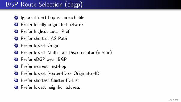
BGP Route Selection (cbgp)
1 Ignore if next-hop is unreachable
2 Prefer locally originated networks
3 Prefer highest Local-Pref
4 Prefer shortest AS-Path
5 Prefer lowest Origin
6 Prefer lowest Multi Exit Discriminator (metric)
7 Prefer eBGP over iBGP
8 Prefer nearest next-hop
9 Prefer lowest Router-ID or Originator-ID
10 Prefer shortest Cluster-ID-List
11 Prefer lowest neighbor address
179 / 470

BGP’s and Count-to-Infinity
BGP does not suffer from the count-to-infinity problem of distance vectorprotocols:
The AS path information allows to detect loops.
However, BGP iteratively explores longer and longer (loop free) paths.
180 / 470

Multiprotocol BGP
Extension to BGP-4 that makes it possible to distribute routing informationfor additional address families
Announced as a capability in the open message
Information for new protocol put into new path attributes
Used to support IPv6, multicast, VPNs, . . .
181 / 470

References
G. Huston.
The BGP Routing Table.The Internet Protocol Journal, 4(1), March 2001.
R. Chandra and P. Traina.
BGP Communities Attribute.RFC 1997, Cisco Systems, August 1996.
Y. Rekhter, T. Li, and S. Hares.
A Border Gateway Protocol 4 (BGP-4).RFC 4271, Juniper Networks, NextHop Technologies, January 2006.
I. van Beijnum.
BGP.O’Reilly, September 2002.
B. Quoitin, C. Pelsser, L. Swinnen, O. Bonaventure, and S. Uhlig.
Interdomain Traffic Engineering with BGP.IEEE Communications Magazine, 41(5):122–128, May 2003.
R. Mahajan, D. Wetherall, and T. Anderson.
Understanding BGP Misconfiguration.In Proc. SIGCOMM 2002. ACM, August 2002.
J. Li, M. Guidero, Z. Wu, E. Purpus, and T. Ehrenkranz.
BGP Routing Dynamics Revisited.SIGCOMM Computer Communication Review, 37(2), April 2007.
182 / 470

Part: Internet Transport Layer (UDP, TCP)
18 Transport Layer Protocol Overview
19 Pseudo Header
20 User Datagram Protocol (UDP)
21 Transmission Control Protocol (TCP)TCP State MachineTCP Flow ControlTCP Congestion ControlTCP Performance
183 / 470

Transport Layer Protocol Overview
18 Transport Layer Protocol Overview
19 Pseudo Header
20 User Datagram Protocol (UDP)
21 Transmission Control Protocol (TCP)TCP State MachineTCP Flow ControlTCP Congestion ControlTCP Performance
184 / 470

Internet Transport Layer
Transport Layer
IP Layer
SMTP HTTP FTP
IP Address + Port Number
IP Address
Network layer addresses identify interfaces on nodes (node-to-nodesignificance).Transport layer addresses identify communicating application processes(end-to-end significance).16-bit port numbers enable the multiplexing and demultiplexing of packetsat the transport layer.
185 / 470

Internet Transport Layer Protocols Overview
The User Datagram Protocol (UDP) provides a simple unreliable best-effortdatagram service.
The Transmission Control Protocol (TCP) provides a bidirectional,connection-oriented and reliable data stream.
The Stream Control Transmission Protocol (SCTP) provides a reliabletransport service supporting sequenced delivery of messages within multiplestreams, maintaining application protocol message boundaries (applicationprotocol framing).
The Datagram Congestion Control Protocol (DCCP) provides a congestioncontrolled, unreliable flow of datagrams suitable for use by applications suchas streaming media.
186 / 470

Pseudo Header
18 Transport Layer Protocol Overview
19 Pseudo Header
20 User Datagram Protocol (UDP)
21 Transmission Control Protocol (TCP)TCP State MachineTCP Flow ControlTCP Congestion ControlTCP Performance
187 / 470

IPv4 Pseudo Header
0 1 2 3
0 1 2 3 4 5 6 7 8 9 0 1 2 3 4 5 6 7 8 9 0 1 2 3 4 5 6 7 8 9 0 1
+-+-+-+-+-+-+-+-+-+-+-+-+-+-+-+-+-+-+-+-+-+-+-+-+-+-+-+-+-+-+-+-+
| Source Address |
+-+-+-+-+-+-+-+-+-+-+-+-+-+-+-+-+-+-+-+-+-+-+-+-+-+-+-+-+-+-+-+-+
| Destination Address |
+-+-+-+-+-+-+-+-+-+-+-+-+-+-+-+-+-+-+-+-+-+-+-+-+-+-+-+-+-+-+-+-+
| unused (0) | Protocol | Length |
+-+-+-+-+-+-+-+-+-+-+-+-+-+-+-+-+-+-+-+-+-+-+-+-+-+-+-+-+-+-+-+-+
Pseudo headers are used during checksum computation.
Excludes header fields that are modified by routers.
188 / 470

IPv6 Pseudo Header
0 1 2 3
0 1 2 3 4 5 6 7 8 9 0 1 2 3 4 5 6 7 8 9 0 1 2 3 4 5 6 7 8 9 0 1
+-+-+-+-+-+-+-+-+-+-+-+-+-+-+-+-+-+-+-+-+-+-+-+-+-+-+-+-+-+-+-+-+
| |
+ +
| |
+ Source Address +
| |
+ +
| |
+-+-+-+-+-+-+-+-+-+-+-+-+-+-+-+-+-+-+-+-+-+-+-+-+-+-+-+-+-+-+-+-+
| |
+ +
| |
+ Destination Address +
| |
+ +
| |
+-+-+-+-+-+-+-+-+-+-+-+-+-+-+-+-+-+-+-+-+-+-+-+-+-+-+-+-+-+-+-+-+
| Upper-Layer Packet Length |
+-+-+-+-+-+-+-+-+-+-+-+-+-+-+-+-+-+-+-+-+-+-+-+-+-+-+-+-+-+-+-+-+
| zero | Next Header |
+-+-+-+-+-+-+-+-+-+-+-+-+-+-+-+-+-+-+-+-+-+-+-+-+-+-+-+-+-+-+-+-+
189 / 470

User Datagram Protocol (UDP)
18 Transport Layer Protocol Overview
19 Pseudo Header
20 User Datagram Protocol (UDP)
21 Transmission Control Protocol (TCP)TCP State MachineTCP Flow ControlTCP Congestion ControlTCP Performance
190 / 470

User Datagram Protocol (UDP)
0 1 2 3
0 1 2 3 4 5 6 7 8 9 0 1 2 3 4 5 6 7 8 9 0 1 2 3 4 5 6 7 8 9 0 1
+-+-+-+-+-+-+-+-+-+-+-+-+-+-+-+-+-+-+-+-+-+-+-+-+-+-+-+-+-+-+-+-+
| Source Port | Destination Port |
+-+-+-+-+-+-+-+-+-+-+-+-+-+-+-+-+-+-+-+-+-+-+-+-+-+-+-+-+-+-+-+-+
| Length | Checksum |
+-+-+-+-+-+-+-+-+-+-+-+-+-+-+-+-+-+-+-+-+-+-+-+-+-+-+-+-+-+-+-+-+
UDP (RFC 768) provides an unreliable datagram transport service.
191 / 470

User Datagram Protocol (UDP)
The Source Port field contains the port number used by the sendingapplication layer process.
The Destination Port field contains the port number used by thereceiving application layer process.
The Length field contains the length of the UDP datagram including theUDP header counted in bytes.
The Checksum field contains the Internet checksum computed over thepseudo header, the UDP header and the payload contained in the UDPpacket.
192 / 470

Transmission Control Protocol (TCP)
18 Transport Layer Protocol Overview
19 Pseudo Header
20 User Datagram Protocol (UDP)
21 Transmission Control Protocol (TCP)TCP State MachineTCP Flow ControlTCP Congestion ControlTCP Performance
193 / 470

Transmission Control Protocol (TCP)
0 1 2 3
0 1 2 3 4 5 6 7 8 9 0 1 2 3 4 5 6 7 8 9 0 1 2 3 4 5 6 7 8 9 0 1
+-+-+-+-+-+-+-+-+-+-+-+-+-+-+-+-+-+-+-+-+-+-+-+-+-+-+-+-+-+-+-+-+
| Source Port | Destination Port |
+-+-+-+-+-+-+-+-+-+-+-+-+-+-+-+-+-+-+-+-+-+-+-+-+-+-+-+-+-+-+-+-+
| Sequence Number |
+-+-+-+-+-+-+-+-+-+-+-+-+-+-+-+-+-+-+-+-+-+-+-+-+-+-+-+-+-+-+-+-+
| Acknowledgment Number |
+-+-+-+-+-+-+-+-+-+-+-+-+-+-+-+-+-+-+-+-+-+-+-+-+-+-+-+-+-+-+-+-+
| Offset| Reserved | Flags | Window |
+-+-+-+-+-+-+-+-+-+-+-+-+-+-+-+-+-+-+-+-+-+-+-+-+-+-+-+-+-+-+-+-+
| Checksum | Urgent Pointer |
+-+-+-+-+-+-+-+-+-+-+-+-+-+-+-+-+-+-+-+-+-+-+-+-+-+-+-+-+-+-+-+-+
| Options | Padding |
+-+-+-+-+-+-+-+-+-+-+-+-+-+-+-+-+-+-+-+-+-+-+-+-+-+-+-+-+-+-+-+-+
TCP (RFC 793) provides a bidirectional connection-oriented and reliabledata stream over an unreliable connection-less network protocol.
194 / 470

Transmission Control Protocol (TCP)
The Source Port field contains the port number used by the sendingapplication layer process.
The Destination Port field contains the port number used by thereceiving application layer process.
The Sequence Number field contains the sequence number of the first databyte in the segment. During connection establishment, this field is used toestablish the initial sequence number.
The Acknowledgment Number field contains the next sequence numberwhich the sender of the acknowledgement expects.
The Offset field contains the length of the TCP header including anyoptions, counted in 32-bit words.
195 / 470

Transmission Control Protocol (TCP)
The Flags field contains a set of binary flags:
URG: Indicates that the Urgent Pointer field is significant.ACK: Indicates that the Acknowledgment Number field is significant.PSH: Data should be pushed to the application as quickly as possible.RST: Reset of the connection.SYN: Synchronization of sequence numbers.FIN: No more data from the sender.
196 / 470

Transmission Control Protocol (TCP)
The Window field indicates the number of data bytes which the sender ofthe segment is willing to receive.
The Checksum field contains the Internet checksum computed over thepseudo header, the TCP header and the data contained in the TCP segment.
The Urgent Pointer field points, relative to the actual segment number,to important data if the URG flag is set.
The Options field can contain additional options.
197 / 470

TCP Connection Establishment
Active Open
SYN x
SYN xACK x+1, SYN y
Passive Open
ACK x+1, SYN y
ACK y+1
ACK y+1
Handshake protocol establishes TCP connection parameters and announcesoptions.
Guarantees correct connection establishment, even if TCP packets are lostor duplicated.
198 / 470

TCP Connection Tear-down
Active Open
FIN x
FIN xACK x+1
Passive Open
ACK x+1
ACK y+1
ACK y+1
ACK x+1, FIN y
ACK x+1, FIN y
TCP provides initially a bidirectional data stream.
A TCP connection is terminated when both unidirectional connections havebeen closed.
It is possible to close only one half of a connection.
199 / 470

TCP State Machine (Part #1)
+---------+ ---------\ active OPEN
| CLOSED | \ -----------
+---------+<---------\ \ create TCB
| ^ \ \ snd SYN
passive OPEN | | CLOSE \ \
------------ | | ---------- \ \
create TCB | | delete TCB \ \
V | \ \
+---------+ CLOSE | \
| LISTEN | ---------- | |
+---------+ delete TCB | |
rcv SYN | | SEND | |
----------- | | ------- | V
+---------+ snd SYN,ACK / \ snd SYN +---------+
| |<----------------- ------------------>| |
| SYN | rcv SYN | SYN |
| RCVD |<-----------------------------------------------| SENT |
| | snd SYN, ACK | |
| |------------------ -------------------| |
+---------+ rcv ACK of SYN \ / rcv SYN,ACK +---------+
| -------------- | | -----------
| x | | snd ACK
| V V
| CLOSE +---------+
| ------- | ESTAB |
| snd FIN +---------+
: CLOSE : : rcv FIN
200 / 470

TCP State Machine (Part #2)
: : :
| V V
| CLOSE +---------+
| ------- | ESTAB |
| snd FIN +---------+
| CLOSE | | rcv FIN
V ------- | | -------
+---------+ snd FIN / \ snd ACK +---------+
| FIN |<----------------- ------------------>| CLOSE |
| WAIT-1 |------------------ | WAIT |
+---------+ rcv FIN \ +---------+
| rcv ACK of FIN ------- | CLOSE |
| -------------- snd ACK | ------- |
V x V snd FIN V
+---------+ +---------+ +---------+
|FINWAIT-2| | CLOSING | | LAST-ACK|
+---------+ +---------+ +---------+
| rcv ACK of FIN | rcv ACK of FIN |
| rcv FIN -------------- | Timeout=2MSL -------------- |
| ------- x V ------------ x V
\ snd ACK +---------+delete TCB +---------+
------------------------>|TIME WAIT|------------------>| CLOSED |
+---------+ +---------+
201 / 470

TCP Flow Control
��������
4K0
����������������
������������
Sender
write(2K)
write(2K)
Receiver
2K | SEQ = 0
2K | SEQ = 2048
ACK = 4096 Win = 0
ACK = 2048 Win = 2048
read(2K)
ACK = 4096 Win = 2048
0 4K
4K0
4K0
Both TCP engines advertise their buffer sizes during connectionestablishment.The available space left in the receiving buffer is advertised as part of theacknowledgements. 202 / 470

Optimizations
Nagle’s Algorithm
When data comes into the sender one byte at a time, just send the first byteand buffer all the rest until the byte in flight has been acknowledgement.This algorithm provides noticeable improvements especially for interactivetraffic where a quickly typing user is connected over a rather slow network.
Clark’s Algorithm
The receiver should not send a window update until it can handle themaximum segment size it advertised when the connection was established oruntil its buffer is half empty.Prevents the receiver from sending a very small window updates (such as asingle byte).
203 / 470

TCP Congestion Control
TCP’s congestion control introduces the concept of a congestion window(cwnd) which defines how much data can be in transit.
The congestion window is maintained by a TCP sender in addition to theflow control receiver window (rwnd) which is advertised by the receiver.
The sender uses these two windows to limit the data that is sent to thenetwork and not yet received (flight size) to the minimum of the receiverand the congestion window:
flightsize ≤ min(cwin, rwin)
The key problem to be solved is the dynamic estimation of the congestionwindow.
204 / 470

TCP Congestion Control (cont.)
The initial window (IW) is usually initialized using the following formula:
IW = min(4 · SMSS ,max(2 · SMSS , 4380bytes))
SMSS is the sender maximum segment size, the size of the largest sementthat the sender can transmit (excluding TCP/IP headers and options).
During slow start, the congestion window cwnd increases by at most SMSSbytes for every received acknowledgement that acknowledges data. Slowstart ends when cwnd exceeds ssthresh or when congestion is observed.
Note that this algorithm leads to an exponential increase if there aremultiple segments acknowledged in the cwnd .
205 / 470

TCP Congestion Control (cont.)
During congestion avoidance, cwnd is incremented by one full-sized segmentper round-trip time (RTT). Congestion avoidance continues until congestionis detected. One formula commonly used to update cwnd during congestionavoidance is given by the following equation:
cwnd = cwnd + (SMSS ∗ SMSS/cwnd)
This adjustment is executed on every incoming non-duplicate ACK.
When congestion is noticed (the retransmission timer expires), then cwnd isreset to 1 full-sized segment and the slow start threshold ssthresh is updatedas follows:
ssthresh = max(flightsize/2, 2 · SMSS)
206 / 470

TCP Congestion Control (cont.)
2 4 106 8 12 14 16 18 20 22 240
4
8
16
12
20
24
28
32
36
40
44co
ng
esti
on
win
do
w (
cwin
)
ssthresh
timeout
26 28
transmission burst number
Congestion control with an initial window size of 2K.
207 / 470

Retransmission Timer
The retransmission timer controls when a segment is resend if noacknowledgement has been received.
The retransmission timer RTT needs to adapt to round-trip time changes.
General idea:
Measure the current round-trip timeMeasure the variation of the round-trip timeUse the estimated round-trip time plus the measured variation to calculatethe retransmit timeoutDo not update the estimators if a segment needs to be retransmitted (Karn’salgorithm).
208 / 470

Retransmission Timer
If an acknowledgement is received for a segment before the associatedretransmission timer expires:
RTT = α · RTT + (1− α)M
M is the measured round-trip time; α is typicall 78.
The standard deviation is estimated using:
D = α · D + (1− α)|RTT −M |
α is a smoothing factor.
The retransmission timeout RTO is determined as follows:
RTO = RTT + 4 · D
The factor 4 has been choosen empirically.209 / 470

Fast Retransmit / Fast Recovery
TCP receivers should send an immediate duplicate acknowledgement whenan out-of-order segment arrives.
The arrival of four identical acknowledgements without the arrival of anyother intervening packets is an indication that a segment has been lost.
The sender performs a fast retransmission of what appears to be the missingsegment, without waiting for the retransmission timer to expire.
Upon a fast retransmission, the sender does not exercise the normalcongestion reaction with a full slow start since acknowledgements are stillflowing.
See RFC 2581 section 3.1 for details.
210 / 470

Karn’s Algorithm
The dynamic estimation of the RTT has a problem if a timeout occurs andthe segment is retransmitted.
A subsequent acknowledgement might acknowledge the receipt of the firstpacket which contained that segment or any of the retransmissions.
Karn suggested that the RTT estimation is not updated for any segmentswhich were retransmitted and that the RTO is doubled on each failure untilthe segment gets through.
The doubling of the RTO leads to an exponential back-off for eachconsecutive attempt.
211 / 470

Explicit Congestion Notification
Idea: Routers signal congestion by setting some special bits in the IP header.
The ECN bits are located in the Type-of-Service field of an IPv4 packet orthe Traffic-Class field of an IPv6 packet.
TCP sets the ECN-Echo flag in the TCP header to indicate that a TCPendpoint has received an ECN marked packet.
TCP sets the Congestion-Window-Reduced (CWR) flag in the TCP headerto acknowledge the receipt of and reaction to the ECN-Echo flag.
=⇒ ECN uses the ECT and CE flags in the IP header for signaling betweenrouters and connection endpoints, and uses the ECN-Echo and CWR flags inthe TCP header for TCP-endpoint to TCP-endpoint signaling.
212 / 470

TCP Performance
Goal: Simple analytic model for steady state TCP behavior.
We only consider congestion avoidance (no slow start).
W (t) denotes the congestion window size at time t.
In steady state, W (t) increases to a maximum value W where it experiencescongestion. As a reaction, the sender sets the congestion window to 1
2W .
The time interval needed to go from 12W to W is T and we can send a
window size of packets every RTT .
Hence, the number N of packets is:
N =1
2
T
RTT
(W
2+ W
)
213 / 470

TCP Performance (cont.)
The time T between two packet losses equals T = RTT ·W /2 since thewindow increases linearly.
By equating the total number of packets transferred during this period, weget
W
4·(
W
2+ W
)=
1
p⇐⇒ W =
√8
3p
where p is the packet loss probability (thus 1p
packets are transmitted
between each packet loss).
The average sending rate X (p), that is the number of packets transmittedduring each period, then becomes:
X (p) =1/p
RTT ·W /2=
1
RTT
√3
2p
214 / 470

TCP Performance (cont.)
Example:
RTT = 200ms, p = 0.05X (p) ≈ 27.4ppsWith 1500 byte segments, the data rate becomes ≈ 32Kbps
Given this formula, it becomes clear that high data rates (say 10Gbps or 1Tbps) require an extremely and unrealistic small packet error rate.
TCP extensions to address this problem can be found in RFC 3649 [?].
215 / 470

References
J. Postel.
User Datagram Protocol.RFC 768, ISI, August 1980.
J. Postel.
Transmission Control Protocol.RFC 793, ISI, September 1981.
M. Allman, V. Paxson, and W. Stevens.
TCP Congestion Control.RFC 2581, NASA Glenn/Sterling Software, ACIRI/ICSI, April 1999.
K. Ramakrishnan, S. Floyd, and D. Black.
The Addition of Explicit Congestion Notification (ECN) to IP.RFC 3168, TeraOptic Networks, ACIRI, EMC, September 2001.
M. Hassan and R. Jain.
High Performance TCP/IP Networking.Prentice Hall, 2004.
S. Floyd.
HighSpeed TCP for Large Congestion Windows.RFC 3649, ICSI, December 2003.
216 / 470

Part: Firewalls and Network Address Translators
22 Middleboxes
23 Firewalls
24 Network Address Translators
25 NAT Traversal (STUN)
217 / 470

Middleboxes
22 Middleboxes
23 Firewalls
24 Network Address Translators
25 NAT Traversal (STUN)
218 / 470

Middleboxes
Definition (RFC 3234)
A middlebox is any intermediary device performing functions other than thenormal, standard functions of an IP router on the datagram path between asource host and destination host [?].
A middlebox is not necessarily a physical box — it is usually just a functionimplemented in some other box.
Middleboxes challenge the End-to-End principle and the hourglass model ofthe Internet architecture.
Middleboxes are popular (whether we like this or not).
219 / 470

Concerns about Middleboxes
Protocols designed without consideration of middleboxes may fail,predictably or unpredictably, in the presence of middleboxes.
Middleboxes introduce new failure modes; rerouting of IP packets aroundcrashed routers is no longer the only case to consider.
Configuration is no longer limited to the two ends of a session; middleboxesmay also require configuration and management.
Diagnosis of failures and misconfigurations is more complex.
220 / 470

Types of Middleboxes
Network Address Translators (NAT): A function that dynamically assigns aglobally unique address to a host that doesn’t have one, without that host’sknowledge.
NAT with Protocol Translator (NAT-PT): A function that performs NATbetween an IPv6 host and an IPv4 network, additionally translating theentire IP header between IPv6 and IPv4 formats.
IP Tunnel Endpoints: Tunnel endpoints, including virtual private networkendpoints, use basic IP services to set up tunnels with their peer tunnelendpoints which might be anywhere in the Internet.
Transport Relays: A middlebox which translates between two transport layerinstances.
221 / 470

Types of Middleboxes (cont.)
Packet classifiers, markers and schedulers: Packet classifiers classify packetsflowing through them according to policy and either select them for specialtreatment or mark them, in particular for differentiated services.
TCP performance enhancing proxies: “TCP spoofer” are middleboxes thatmodify the timing or action of the TCP protocol in flight for the purposes ofenhancing performance.
Load balancers that divert/munge packets: Techniques that divert packetsfrom their intended IP destination, or make that destination ambiguous.
IP Firewalls: A function that screens and rejects packets based purely onfields in the IP and Transport headers.
Application Firewalls: Application-level firewalls act as a protocol end pointand relay
222 / 470

Types of Middleboxes (cont.)
Application-level gateways (ALGs): ALGs translate IP addresses inapplication layer protocols and typically complement IP firewalls.
Transcoders: Functions performing some type of on-the-fly conversion ofapplication level data.
Proxies: An intermediary program which acts as both a server and a clientfor the purpose of making requests on behalf of other clients.
Caches: Caches are functions typically intended to optimise response times.
Anonymisers: Functions that hide the IP address of the data sender orreceiver. Although the implementation may be distinct, this is in practicevery similar to a NAT plus ALG.
. . .
223 / 470

Firewalls
22 Middleboxes
23 Firewalls
24 Network Address Translators
25 NAT Traversal (STUN)
224 / 470

Firewalls
A firewall is a system (or a set of systems) that enforce access controlpolicies between two (or more) networks.
Conservative firewalls allow known desired traffic and reject everything else.
Optimistic firewalls reject known unwanted traffic and allow the rest.
Firewalls typically consist of packet filters, transport gateways andapplication level gateways.
Firewalls not only protect the “inside” from the “outside”, but also the“outside” from the “inside”.
⇒ There are many ways to circumvent firewalls if internal and external hostscooperate.
225 / 470

Firewall Architectures
External Network(Internet)
Internal Network(Intranet)
Packet Filter
The simplest architecture is a packet filter which is typically implementedwithin a router that connects the internal network with the external network.
Sometimes called a “screening router”.
226 / 470

Firewall Architectures
Bastion Host
External Network(Internet)
Internal Network(Intranet)
A bastion host is a multihomed host connected to the internal and externalnetwork which does not forward IP datagrams but instead provides suitablegateways.
Effectively prevents any direct communication between hosts on the internalnetwork with hosts on the external network.
227 / 470

Firewall Architectures
(Intranet)Internal Network
(Internet)External Network
Packet FilterPacket Filter
(HTTP, SMTP, DNS, ...)Server
Demilitarized Zone (DMZ)
Bastion Host
The most common architecture consists of two packet filters which create ademilitarized zone (DMZ).
Externally visible servers and gateways are located in the DMZ.
228 / 470

Packetfilter Example: Linux ipchains
inputchains
forwarding
local process
checksum & sanitychecks
outputchains
forwardchains
Input chains are lists of filter rules applied to all incoming IP packets.
Output chains are lists of filter rules applied to all outgoing IP packet.
Forward chains are lists of fiter rules applied to all forwarded IP packets.
229 / 470

Network Address Translators
22 Middleboxes
23 Firewalls
24 Network Address Translators
25 NAT Traversal (STUN)
230 / 470

Network Address Translators
Basic Network Address Translation (NAT):Translates private IP addresses into public IP addresses.
Network Address Port Translation (NAPT):Translates transport endpoint identifiers. NAPT allows to share a singlepublic address among many private addresses (masquerading).
Bi-directional NAT (Two-Way NAT):Translates outbound and inbound and uses DNS-ALGs to facilitatebi-directional name to address mappings.
Twice NAT :A variation of a NAT which modifies both the source and destinationaddresses of a datagram. Used to join overlapping address domains.
231 / 470

Network Address Port Translation Example
4321
(Internet)
Internal Network
(Intranet)
Network Address
Port Translator
Ext. Port Int. IP
10.50.1.1212.201.44.241
212.201.44.241
212.201.44.241 10.50.1.1
10.50.1.2
12345
54321
15243
Ext. IP Int. Port
1234
1234
External Network
232 / 470
Full Cone NAT
A full cone NAT is a NAT where all requests from the same internal IPaddress and port are mapped to the same external IP address and port.
Any external host can send a packet to the internal host, by sending apacket to the mapped external address.
233 / 470
Restricted Cone NAT
A restricted cone NAT is a NAT where all requests from the same internalIP address and port are mapped to the same external IP address and port.
Unlike a full cone NAT, an external host (with IP address X) can send apacket to the internal host only if the internal host had previously sent apacket to IP address X.
234 / 470

Port Restricted Cone NAT
A port restricted cone NAT is like a restricted cone NAT, but the restrictionincludes port numbers.
Specifically, an external host can send a packet, with source IP address Xand source port P, to the internal host only if the internal host hadpreviously sent a packet to IP address X and port P.
235 / 470

Symmetric NAT
A symmetric NAT is a NAT where all requests from the same internal IPaddress and port, to a specific destination IP address and port, are mappedto the same external IP address and port.
If the same host sends a packet with the same source address and port, butto a different destination, a different mapping is used.
Only the external host that receives a packet can send a UDP packet backto the internal host.
236 / 470

NAT Traversal (STUN)
22 Middleboxes
23 Firewalls
24 Network Address Translators
25 NAT Traversal (STUN)
237 / 470

STUN (RFC 5389)
Session Traversal Utilities for NAT (STUN)
Client / server protocol used for NAT discovery:1 The client sends a request to a STUN server2 The server returns a response containing the IP address seen by the server
(i.e., a mapped address)3 The client compares its IP address with the IP address returned by the
server; if they are different, the client is behind a NAT and learns its mappedaddress
RFC 5780 details a number of tests that can be performed using STUN todetermine the behaviour of a NAT.
238 / 470

References
B. Carpenter and S. Brim.
Middleboxes: Taxonomy and Issues.RFC 3234, IBM Zurich Research Laboratory, February 2002.
P. Srisuresh and M. Holdrege.
IP Network Address Translator (NAT) Terminology and Considerations.RFC 2663, Lucent Technologies, August 1999.
B. Carpenter.
Internet Transparency.RFC 2775, IBM, February 2000.
N. Freed.
Behavior of and Requirements for Internet Firewalls.RFC 2979, Sun, October 2000.
J. Rosenberg, J. Weinberger, C. Huitema, and R. Mahy.
STUN - Simple Traversal of User Datagram Protocol (UDP) Through Network Address Translators (NATs).RFC 3489, dynamicsoft, Microsoft, Cisco, March 2003.
E. D. Zwicky, S. Cooper, and D. B. Chapman.
Building Internet Firewalls.O’Reilly, 2 edition, 2000.
239 / 470

Part: Security at the Network and Transport Layer
26 Cryptography Primer
27 Internet Protocol Security (IPsec)
28 Transport Layer Security (TLS)
29 Secure Shell (SSH)
240 / 470

Cryptography Primer
26 Cryptography Primer
27 Internet Protocol Security (IPsec)
28 Transport Layer Security (TLS)
29 Secure Shell (SSH)
241 / 470

Terminology (Cryptography)
Cryptology subsumes cryptography and cryptanalysis:
Cryptography is the art of secret writing.Cryptanalysis is the art of breaking ciphers.
Encryption is the process of converting plaintext into an unreadable form,termed ciphertext.
Decryption is the reverse process, recovering the plaintext back from theciphertext.
A cipher is an algorithm for encryption and decryption.
A key is some secret piece of information used as a parameter of a cipherand customises the algorithm used to produce ciphertext.
242 / 470

Cryptosystem
Definition
A cryptosystem is a quintuple (M ,C ,K ,Ek ,Dk), where
M is a cleartext space,
C is a chiffretext space,
K is a key space,
Ek : M → C is an encryption transformation with k ∈ K , and
Dk : C → M is a decryption transformation with k ∈ K .
For a given k and all m ∈ M , the following holds:
Dk(Ek(m)) = m
243 / 470

Cryptosystem Requirements
The transformations Ek and Dk must be efficient to compute.
It must be easy to find a key k ∈ K and the functions Ek and Dk .
The security of the system rests on the secrecy of the key and not on thesecrecy of the algorithms.
For a given c ∈ C , it is difficult to systematically compute
Dk even if m ∈ M with Ek(m) = c is knowna cleartext m ∈ M such that Ek(m) = c .
For a given c ∈ C , it is difficult to systematically determine
Ek even if m ∈ M with Ek(m) = c is knownc ′ ∈ C with c ′ 6= c such that Dk(c ′) is a valid cleartext in M.
244 / 470

Symmetric vs. Asymmetric Cryptosystems
Symmetric Cryptosystems
Both (all) parties share the same key and the key needs to be kept secret.
Examples: AES, DES (outdated), Twofish, Serpent, IDEA, . . .
Asymmetric Cryptosystems
Each party has a pair of keys: one key is public and used for encryptionwhile the other key is private and used for decryption.
Examples: RSA, DSA, ElGamal, . . .
245 / 470

Cryptographic Hash Functions
Definition
A cryptographic hash function H is a hash function which meets the followingrequirements:
1 The hash function is efficient to compute for arbitrary cleartexts m.
2 Given h it should be hard to find any m such that h = H(m).
3 Given an input m1, it should be hard to find another input m2 6= m1 suchthat H(m1) = H(m2).
4 It should be hard to find two different messages m1 and m2 such thatH(m1) = H(m2).
Cryptographic hash functions are used to compute a fixed size fingerprint(message digest) of a variable length clear text.
246 / 470

Digital Signatures
Digital signatures are used to prove the authenticity of a message (ordocument) and its integrity.
The receiver can verify the claimed identity of the sender.The sender can not deny that it did sent the message.The receiver can not tamper the message itself.
Digitally signing a message (or document) means that
the sender puts a signature into a message (or document) that can beverified andthat we can be sure that the signature cannot be faked (e.g., copied fromsome other message)
Digital signatures are often implemented by signing a cryptographic hash ofthe original message (or document) since this is usually less computationallyexpensive
247 / 470

Internet Protocol Security (IPsec)
26 Cryptography Primer
27 Internet Protocol Security (IPsec)
28 Transport Layer Security (TLS)
29 Secure Shell (SSH)
248 / 470
IPsec in a Nutshell
Goal: Secure packets at the IP network layer
Modes:
Transport mode:The IPsec header is inserted just after the IP headerTunnel mode:A complete IP packet is encapsulated in a new IP packet
A Security Association (SA) is a simplex association between two IPsecendpoints
For duplex unicast communication, two SAs must be established
249 / 470
IPsec Headers
The IP Authentication Header (AH) offers integrity and data originauthentication, with optional (at the discretion of the receiver) anti-replayfeatures
The Encapsulating Security Payload (ESP) protocol offers the same set ofservices, and also offers confidentiality
Both AH and ESP offer access control, enforced through the distribution ofcryptographic keys and the management of traffic flows as dictated by theSecurity Policy Database (SPD)
The index into the SPD is called the SPI and typically used to identify SAs
250 / 470

IPsec AH (RFC 4302)
0 1 2 3
0 1 2 3 4 5 6 7 8 9 0 1 2 3 4 5 6 7 8 9 0 1 2 3 4 5 6 7 8 9 0 1
+-+-+-+-+-+-+-+-+-+-+-+-+-+-+-+-+-+-+-+-+-+-+-+-+-+-+-+-+-+-+-+-+
| Next Header | Payload Len | RESERVED |
+-+-+-+-+-+-+-+-+-+-+-+-+-+-+-+-+-+-+-+-+-+-+-+-+-+-+-+-+-+-+-+-+
| Security Parameters Index (SPI) |
+-+-+-+-+-+-+-+-+-+-+-+-+-+-+-+-+-+-+-+-+-+-+-+-+-+-+-+-+-+-+-+-+
| Sequence Number Field |
+-+-+-+-+-+-+-+-+-+-+-+-+-+-+-+-+-+-+-+-+-+-+-+-+-+-+-+-+-+-+-+-+
| |
+ Integrity Check Value-ICV (variable) |
| |
+-+-+-+-+-+-+-+-+-+-+-+-+-+-+-+-+-+-+-+-+-+-+-+-+-+-+-+-+-+-+-+-+
251 / 470

IPsec ESP (RFC 4303)
0 1 2 3
0 1 2 3 4 5 6 7 8 9 0 1 2 3 4 5 6 7 8 9 0 1 2 3 4 5 6 7 8 9 0 1
+-+-+-+-+-+-+-+-+-+-+-+-+-+-+-+-+-+-+-+-+-+-+-+-+-+-+-+-+-+-+-+-+ ----
| Security Parameters Index (SPI) | ^Int.
+-+-+-+-+-+-+-+-+-+-+-+-+-+-+-+-+-+-+-+-+-+-+-+-+-+-+-+-+-+-+-+-+ |Cov-
| Sequence Number | |ered
+-+-+-+-+-+-+-+-+-+-+-+-+-+-+-+-+-+-+-+-+-+-+-+-+-+-+-+-+-+-+-+-+ | ----
| Payload Data* (variable) | | ^
~ ~ | |
| | |Conf.
+ +-+-+-+-+-+-+-+-+-+-+-+-+-+-+-+-+-+-+-+-+-+-+-+-+ |Cov-
| | Padding (0-255 bytes) | |ered*
+-+-+-+-+-+-+-+-+ +-+-+-+-+-+-+-+-+-+-+-+-+-+-+-+-+ | |
| | Pad Length | Next Header | v v
+-+-+-+-+-+-+-+-+-+-+-+-+-+-+-+-+-+-+-+-+-+-+-+-+-+-+-+-+-+-+-+-+ ------
| Integrity Check Value-ICV (variable) |
~ ~
| |
+-+-+-+-+-+-+-+-+-+-+-+-+-+-+-+-+-+-+-+-+-+-+-+-+-+-+-+-+-+-+-+-+
252 / 470

IPsec Keying
Manual keying (not really recommended)
Automatic keying with the Internet Key Exchange (IKEv2) protocol(currently version 2).
IKEv2 itself uses the Diffie-Hellman algorithm plus certificates.IKEv2 is a simplified version IKEv1 (which happened to be too complicated).
No widespread deployment of an automatic keying infrastructure and as aconsequence transport-mode IPsec is not widely used on the open Internet.
Tunnel-mode IPsec has seen larger deployment in order to build securetunnels into enterprise networks (also known as Virtual Private Networks,VPNs).
253 / 470

Manual Keying Example
#!/usr/sbin/setkey -f
# Clear the sa database and the spd database
flush;
spdflush;
# Traffic going from 212.201.49.188 to 10.70.17.11 needs an AH signed
# using HMAC-SHA1 using secret 12345678901234567890
add 212.201.49.188 10.70.17.11 ah 15700 -A hmac-sha1 "12345678901234567890";
# Traffic going from 212.201.49.188 to 10.70.17.11 needs encryption
# using 3des-cbc with key 123456789012123456789012’
add 212.201.49.188 10.70.17.11 esp 15701 -E 3des-cbc "123456789012123456789012";
# Traffic going out to 10.70.17.11 must be encrypted and be wrapped
# in an AH authentication header.
spdadd 212.201.49.188 10.70.17.11 any -P out ipsec
esp/transport//require
ah/transport//require;
254 / 470
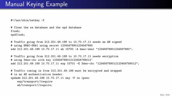
Manual Keying Example
#!/usr/sbin/setkey -f
# Clear the sa database and the spd database
flush;
spdflush;
# Traffic going from 212.201.49.188 to 10.70.17.11 needs an AH signed
# using HMAC-SHA1 using secret 12345678901234567890
add 212.201.49.188 10.70.17.11 ah 15700 -A hmac-sha1 "12345678901234567890";
# Traffic going from 212.201.49.188 to 10.70.17.11 needs encryption
# using 3des-cbc with key 123456789012123456789012’
add 212.201.49.188 10.70.17.11 esp 15701 -E 3des-cbc "123456789012123456789012";
# Traffic coming in from 212.201.49.188 must be encrypted and wrapped
# in an AH authentication header.
spdadd 212.201.49.188 10.70.17.11 any -P in ipsec
esp/transport//require
ah/transport//require;
255 / 470

Transport Layer Security (TLS)
26 Cryptography Primer
27 Internet Protocol Security (IPsec)
28 Transport Layer Security (TLS)
29 Secure Shell (SSH)
256 / 470

Transport Layer Security
Transport Layer Security (TLS), formerly known as Secure Socket Layer(SSL), was created by Netscape in order to secure data transfers on theWeb.
As a user-space implementation, TLS can be shipped with applications anddoes not require operating system support.
TLS uses X.509 certificates to authenticate servers and clients (althoughclient authentication is often not used at the TLS layer).
X.509 certificates more or less require a public key infrastructure includingrevocation server.
TLS is widely used to secure application protocols running over TCP (e.g.,http, smtp, ftp, telnet, imap, . . . )
257 / 470

X.509 Certificate ASN.1 Definition
Certificate ::= SEQUENCE {
tbsCertificate TBSCertificate,
signatureAlgorithm AlgorithmIdentifier,
signatureValue BIT STRING }
TBSCertificate ::= SEQUENCE {
version [0] EXPLICIT Version DEFAULT v1,
serialNumber CertificateSerialNumber,
signature AlgorithmIdentifier,
issuer Name,
validity Validity,
subject Name,
subjectPublicKeyInfo SubjectPublicKeyInfo,
issuerUniqueID [1] IMPLICIT UniqueIdentifier OPTIONAL,
-- If present, version MUST be v2 or v3
subjectUniqueID [2] IMPLICIT UniqueIdentifier OPTIONAL,
-- If present, version MUST be v2 or v3
extensions [3] EXPLICIT Extensions OPTIONAL
-- If present, version MUST be v3
}
258 / 470

X.509 Certificate ASN.1 Definition
Version ::= INTEGER { v1(0), v2(1), v3(2) }
CertificateSerialNumber ::= INTEGER
Validity ::= SEQUENCE {
notBefore Time,
notAfter Time }
Time ::= CHOICE {
utcTime UTCTime,
generalTime GeneralizedTime }
UniqueIdentifier ::= BIT STRING
SubjectPublicKeyInfo ::= SEQUENCE {
algorithm AlgorithmIdentifier,
subjectPublicKey BIT STRING }
Extensions ::= SEQUENCE SIZE (1..MAX) OF Extension
Extension ::= SEQUENCE {
extnID OBJECT IDENTIFIER,
critical BOOLEAN DEFAULT FALSE,
extnValue OCTET STRING
-- contains the DER encoding of an ASN.1 value
-- corresponding to the extension type identified
-- by extnID
}
259 / 470

X.509 Subject Alternative Name Extension
id-ce-subjectAltName OBJECT IDENTIFIER ::= { id-ce 17 }
SubjectAltName ::= GeneralNames
GeneralNames ::= SEQUENCE SIZE (1..MAX) OF GeneralName
GeneralName ::= CHOICE {
otherName [0] OtherName,
rfc822Name [1] IA5String,
dNSName [2] IA5String,
x400Address [3] ORAddress,
directoryName [4] Name,
ediPartyName [5] EDIPartyName,
uniformResourceIdentifier [6] IA5String,
iPAddress [7] OCTET STRING,
registeredID [8] OBJECT IDENTIFIER }
OtherName ::= SEQUENCE {
type-id OBJECT IDENTIFIER,
value [0] EXPLICIT ANY DEFINED BY type-id }
EDIPartyName ::= SEQUENCE {
nameAssigner [0] DirectoryString OPTIONAL,
partyName [1] DirectoryString }
260 / 470

TLS Record Protocol
Record Protocol
The record protocol takes messages to be transmitted, fragments the data intomanageable blocks, optionally compresses the data, adds a messageauthentication code, and encrypts and transmits the result. Received data isdecrypted, verified, decompressed, reassembled, and then delivered to higher-levelclients.
The record layer is used by the handshake protocol, the change cipher specprotocol, the alert protocol, and the application data protocol.
The fragmentation and reassembly provided does not preserve applicationmessage boundaries.
261 / 470
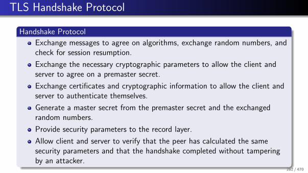
TLS Handshake Protocol
Handshake Protocol
Exchange messages to agree on algorithms, exchange random numbers, andcheck for session resumption.
Exchange the necessary cryptographic parameters to allow the client andserver to agree on a premaster secret.
Exchange certificates and cryptographic information to allow the client andserver to authenticate themselves.
Generate a master secret from the premaster secret and the exchangedrandom numbers.
Provide security parameters to the record layer.
Allow client and server to verify that the peer has calculated the samesecurity parameters and that the handshake completed without tamperingby an attacker.
262 / 470

TLS Change Cipher Spec Protocol
Change Cipher Spec Protocol
The change cipher spec protocol is used to signal transitions in cipheringstrategies.
The protocol consists of a single ChangeCipherSpec message.
This message is sent by both the client and the server to notify the receivingparty that subsequent records will be protected under the newly negotiatedCipherSpec and keys.
263 / 470

TLS Alert Protocol
Alert Protocol
The alert protocol is used to signal exceptions (warnings, errors) that occuredduring the processing of TLS protocol messages. An alert has an alert level andan alert description (enumeration).
The alert protocol is used to properly close a TLS connection by exchangingclose notify alert messages.
The closure exchange allows to detect truncation attacks.
264 / 470
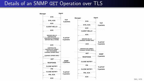
Details of an SNMP GET Operation over TLS
Manager Agent
3 packetsTCP
6 packetsTLS/TCP
2 packetsSNMP
5 packetsTLS/TCP
CHANGE CIPHER SPEC
SYN
SYN, ACK
FIN
CLOSE NOTIFY
ACK
GET
CHANGE CIPHER SPEC
ACK
CLIENT HELLO
ACK
FIN, ACK
CLOSE NOTIFY
RESPONSE
KEY EXCHANGECERTIFICATE VERIFY
CERTIFICATE
SERVER HELLOCERTIFICATE
CERTIFICATE REQUESTSERVER HELLO DONE
ACK
3 packets
AgentManager
SNMP
TLS/TCP5 packets
5 packets
TCP
TLS/TCP
2 packets
CERTIFICATE VERIFY
ACK
SYN
SYN, ACK
CLIENT HELLO
ACK
ACK
GET
CLOSE NOTIFY
FIN
CLOSE NOTIFY
FIN, ACK
ACK
CHANGE CIPHER SPEC
CHANGE CIPHER SPECSERVER HELLO
RESPONSE
265 / 470
Secure Shell (SSH)
26 Cryptography Primer
27 Internet Protocol Security (IPsec)
28 Transport Layer Security (TLS)
29 Secure Shell (SSH)
266 / 470
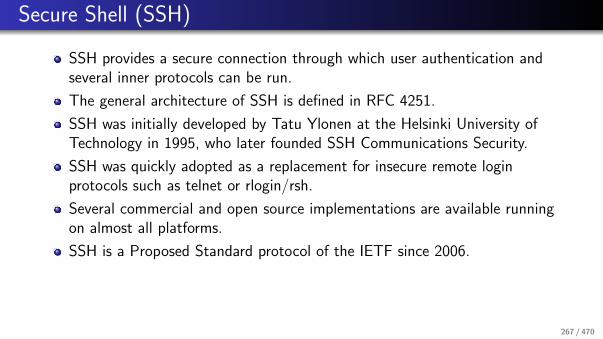
Secure Shell (SSH)
SSH provides a secure connection through which user authentication andseveral inner protocols can be run.
The general architecture of SSH is defined in RFC 4251.
SSH was initially developed by Tatu Ylonen at the Helsinki University ofTechnology in 1995, who later founded SSH Communications Security.
SSH was quickly adopted as a replacement for insecure remote loginprotocols such as telnet or rlogin/rsh.
Several commercial and open source implementations are available runningon almost all platforms.
SSH is a Proposed Standard protocol of the IETF since 2006.
267 / 470

SSH Protocol Overview
SSH Protocol Layers
1 The Transport Layer Protocol provides server authentication,confidentiality, and integrity with perfect forward secrecy
2 The User Authentication Protocol authenticates the client-side user tothe server
3 The Connection Protocol multiplexes the encrypted data stream intoseveral logical channels
⇒ SSH authentication is not symmetric!
⇒ The SSH protocol is designed for clarity, not necessarily for efficiency (showsits academic roots)
268 / 470

SSH Terminology
Host Key
Every machine must have a public/private host key pair. Host Keys are oftenidentified by their fingerprint.
User Key
Users may have their own public/private key pairs.
User Password
Accounts may have passwords to authenticate users.
Passphrase
The storage of a user’s private key may be protected by a passphrase.
269 / 470

SSH Features: TCP Forwarding
ssh −f [email protected] −L 2000:example.com:25 −N
sm
tp
ss
h
22 25
ss
h
ma
il2000 encrypted
example.com
TCP Forwarding
TCP forwarding allows users to tunnel unencrypted traffic through an encryptedSSH connection.
270 / 470

SSH Features: X11 Forwarding
DISPLAY
ss
h
X1
1encrypted
example.com
ssh −X [email protected]
xe
ye
s
ss
h
22
multiple channels
X11 Forwarding
X11 forwarding is a special application of TCP forwarding allowing X11 clients onremote machines to access the local X11 server (managing the display and thekeyboard/mouse).
271 / 470

SSH Features: Connection Sharing
ss
h
encrypted
example.com
ss
h
ss
h
22
multiple channelss
sh
local socket
Connection Sharing
New SSH connections hook as a new channel into an existing SSH connection,reducing session startup times (speeding up shell features such as tab expansion).
272 / 470

SSH Features: IP Tunneling
10
.0.9
9.0
/24
ss
h
encrypted
example.com
ss
h
ss
h
ssh −f −w 0:1 example.com
tun0
IP
10.1.1.1
IP
tun110.1.1.2
ifconfig tun0 10.1.1.1 10.1.1.2 \
route add 10.0.99.0/24 10.1.1.2
netmask 255.255.255.255 netmask 255.255.255.255
route add 10.0.50.0/24 10.1.1.1
ifconfig tun0 10.1.1.2 10.1.1.1 \
10
.0.5
0.0
/24
IP Tunneling
Tunnel IP packets over an SSH connection by inserting tunnel interfaces into thekernels and by configuring IP forwarding.
273 / 470
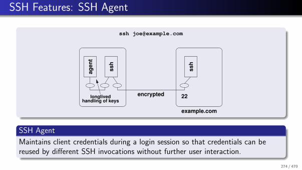
SSH Features: SSH Agent
ss
h
ag
en
tencrypted
example.com
ss
h
22longlivedhandling of keys
SSH Agent
Maintains client credentials during a login session so that credentials can bereused by different SSH invocations without further user interaction.
274 / 470

SSH Features: SSH Agent Forwarding
ss
h
ag
en
tencrypted
example.com
ss
h
22longlivedhandling of keys
ss
h
multiple channels
forwardedagent endpoint
SSH Agent Forwarding
An SSH server emulates an SSH Agent and forwards requests to the SSH Agentof its client, creating a chain of SSH Agent delegations.
275 / 470

Details of an SNMP GET Operation over SSH
packets
Manager Agent
3 TCP
10 SSHtransport
packets
packets
2 TCP
HELLO
KEX_INIT
KEXDH_INIT
KEXDH_REPLY
NEWKEYS
SERVICE_REQUEST
SERVICE_ACCEPT
NEWKEYS
SYN, ACK
ACK
KEX_INIT
HELLO
SYN
ACK
ACK
3 TCP
2 SSH
2 SSHchannel
user auth
6 SSH
packets
packets
packets
packets
packets
2 SNMP
AgentManager
RESPONSE
CHANNEL_OPEN
FIN, ACK
DISCONNECT
USERAUTH_FAILURE
USERAUTH_REQUEST
GET
USERAUTH_FAILURE
FIN, ACK
CHANNEL_OPEN_CONF.
ACK
USERAUTH_REQUEST
USERAUTH_SUCCESS
USERAUTH_REQUEST
DISCONNECT
276 / 470

SSH Transport Protocol
Transport Protocol (RFC 4253) provides
strong encryption,server authentication,integrity protection, andoptionally compression.
SSH transport protocol typically runs over TCP
3DES (required), AES128 (recommended)
HMAC-SHA1 (recommended)
Automatic key re-exchange, usually after 1 GB of data have been transferredor after 1 hour has passed, whichever is sooner.
277 / 470

SSH Key Exchange
The SSH host key keyex identifies a server by its hostname or IP addressand possibly port number.
Other keyex mechanisms use different naming schemes for a host.
Different key exchange algorithms
Diffie-Hellman style key exchangeGSS-API style key exchange
Different Host key algorithms
Host key used to authenticate key exchangeSSH RSA and DSA keysX.509 (under development)
278 / 470

SSH User Authentication
Executes after transport protocol initialization (key exchange) toauthenticate client.
Authentication methods:
Password (classic password authentication)Interactive (challenge response authentication)Host-based (uses host key for user authentication)Public key (usually DSA or RSA keypairs)GSS-API (Kerberos / NETLM authentication)X.509 (under development)
Authentication is client-driven.
279 / 470

SSH Connection Protocol
Allows opening of multiple independent channels.
Channels may be multiplexed in a single SSH connection.
Channel requests are used to relay out-of-band channel specific data (e.g.,window resizing information).
Channels commonly used for TCP forwarding.
280 / 470

OpenSSH Implementation
Privilege Separation
Privilege separation is a technique in which a program is divided into parts whichare limited to the specific privileges they require in order to perform a specifictask.
OpenSSH is using two processes: one running with special privileges and onerunning under normal user privileges
The process with special privileges carries out all operations requiring specialpermissions.
The process with normal user privileges performs the bulk of thecomputation not requiring special rights.
Bugs in the code running with normal user privileges do not give specialaccess rights to an attacker.
281 / 470

Performance of Short Lived Sessions
ProtocolTime (meat) [ms] Time (turtle) [ms]
Data [bytes] Packetsmin avg max min avg max
v1/CSM/UDP/nn 0.24 0.25 0.29 0.85 0.95 1.43 292 2v1/CSM/TCP/nn 0.39 0.40 0.43 1.27 1.38 1.72 1012 10v2/CSM/UDP/nn 0.24 0.25 0.30 0.85 0.96 1.50 292 2v2/CSM/TCP/nn 0.46 0.48 0.58 1.28 1.46 2.40 1012 10v3/USM/UDP/nn 0.48 0.48 0.54 1.75 1.84 1.95 718 4v3/USM/TCP/nn 0.63 0.64 0.69 2.22 2.46 9.59 1490 12v3/USM/UDP/an 0.50 0.63 0.87 1.79 1.89 2.34 742 4v3/USM/TCP/an 0.65 0.66 0.70 2.21 2.31 2.48 1514 12v3/USM/UDP/ap 0.51 0.52 0.59 1.88 2.05 4.17 763 4v3/USM/TCP/ap 0.66 0.68 0.71 2.31 2.42 2.60 1535 12v3/TSM/SSH/ap 13.49 13.73 14.20 107.35 110.45 144.33 5310 31v3/TSM/TLS/ap 11.01 11.15 12.57 67.44 68.70 86.59 4107 16
v3/TSM/DTLS/ap 10.89 11.05 12.00 67.68 69.96 155.10 3457 8v3/TSM/TLSsr/ap 2.23 2.27 2.45 5.47 5.72 6.28 1457 15
SSH (TLS/DTLS) transports behave like a DoS attack for short-livedSNMP sessions (e.g., shell scripts)
TLS’s session resumption mechanism cures the problem
How can we do session resumption with SSH?
282 / 470

Session Resumption Key Exchange
NEWKEYS
Client
KEXINIT
KEXINIT
KEX_SR_INIT
KEX_SR_OK
Server
NEWKEYS
Server maintains session state for recently closed sessions
Client and server perform session resumption by using of a sessionresumption key exchange algorithm
SSH’s algorithm negotiation feature handles this nicely
283 / 470

Session Resumption with Server Side State
Algorithm (Server Side State)
C: Client sends the session identifier and a MAC computed over the sessionkeys to the server in a SSH2 MSG KEXSR INIT message
S: Server looks up the cached session and verifies the MAC
If successful, it returns an SSH2 MSG KEX SR OK message, followed by astandard SSH2 MSG NEWKEYS exchangeOn failure, SSH2 MSG KEX SR ERROR is sent and key exchange proceeds withanother key exchange algorithm, or fails
+ Simple design and easy to implement
− Server has to maintain session state (scalability)
284 / 470

Session Resumption with Client Side State
Algorithm (Client Side State)
S: After key (re)negotiation, the server sends an encrypted ticket in aSSH2 MSG KEX SR TICKET message
C: The client sends the encrypted ticket and a MAC computed over the sessionidentifier to the server in a SSH2 MSG KEXSR INIT message
S: The server decrypts the ticket and verifies the MAC
If successful, it returns an SSH2 MSG KEX SR OK message, followed by astandard SSH2 MSG NEWKEYS exchange.On failure, SSH2 MSG KEX SR ERROR is sent and key exchange proceeds withanother key exchange algorithm, or fails.
+ Server side state reduced to a key for encrypting tickets
285 / 470

TicketContent Data Structure
struct TicketEnc { struct TicketContent {
char* name; u_char* session_id;
u_char* key; u_int session_id_len;
u_char* iv; TicketEnc tenc_ctos;
}; TicketEnc tenc_stoc;
TicketMac tmac_ctos;
TicketMac tmac_stoc;
struct TicketMac { char* tcomp_ctos;
char* name; char* tcomp_stoc;
u_char* key; int hostkey_type;
}; char* client_version_string;
char* server_version_string;
};
SSH allows to use different algorithms in each direction!
286 / 470

Ticket Data Structure
struct Ticket {
u_int seq_nr;
u_char* id;
u_char* enc_ticket;
u_int enc_ticket_len;
int64_t time_stamp;
};
Contains the encrypted TicketContent data structure in enc ticket
The id uniquely identifiers a ticket
The seq nr and time stamp fields can be used to quickly discard outdatedtickets
Encryption key and its IV are generated at server start-up
287 / 470
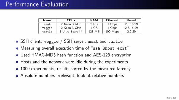
Performance Evaluation
Name CPUs RAM Ethernet Kernelmeat 2 Xeon 3 GHz 2 GB 1 Gbps 2.6.16.29
veggie 2 Xeon 3 GHz 1 GB 1 Gbps 2.6.16.29turtle 1 Ultra Sparc IIi 128 MB 100 Mbps 2.6.20
SSH client: veggie / SSH server: meat and turtle
Measuring overall execution time of “ssh $host exit”
Used HMAC-MD5 hash function and AES-128 encryption
Hosts and the network were idle during the experiments
1000 experiments, results sorted by the measured latency
Absolute numbers irrelevant, look at relative numbers
288 / 470

Session Resumption Performance (key length 1024)
100
120
140
160
180
200
220
240
0 100 200 300 400 500 600 700 800 900 1000
ove
rall
late
ncy [
ms]
test runs (sorted by increasing latency)
impact of session resumption on meat (key len 1024 bit)
session resumptionno session resumption
100
200
300
400
500
600
0 100 200 300 400 500 600 700 800 900 1000
ove
rall
late
ncy [
ms]
test runs (sorted by increasing latency)
impact of session resumption on turtle (key len 1024 bit)
session resumptionno session resumption
With a key length of 1024 bits, the performance gain on an idle fastmachine is observable but small
With the same key length, the performance gain on a small idle machine issignificant (factor 4)
⇒ Session resumption is particularly useful for processing power constrainedlow-end consumer /enterprise products
289 / 470

Impact of the Key Length on the Performance
100
150
200
250
300
350
0 100 200 300 400 500 600 700 800 900 1000
ove
rall
late
ncy [
ms]
test runs (sorted by increasing latency)
impact of session resumption on meat (varying key len)
sr (3072 bit)no sr (1024 bit)no sr (2048 bit)no sr (3072 bit)
Session resumption performance is largely independent of the key length
With increasing key length, the performance gain increases also on fast idlemachines
⇒ Even on a fast processors, the performance gain is significant if you needlong keys to achieve strong security
290 / 470
References I
S. Kent and K. Seo.
Security Architecture for the Internet Protocol.RFC 4301, BBN Technologies, December 2005.
S. Kent.
IP Authentication Header.RFC 4302, BBN Technologies, December 2005.
S. Kent.
IP Encapsulating Security Payload (ESP).RFC 4303, BBN Technologies, December 2005.
T. Ylonen and C. Lonvick.
The Secure Shell (SSH) Protocol Architecture.RFC 4251, SSH Communications Security Corp, Cisco Systems, January 2006.
T. Ylonen and C. Lonvick.
The Secure Shell (SSH) Authentication Protocol.RFC 4252, SSH Communications Security Corp, Cisco Systems, January 2006.
T. Ylonen and C. Lonvick.
The Secure Shell (SSH) Transport Layer Protocol.RFC 4253, SSH Communications Security Corp, Cisco Systems, January 2006.
291 / 470

References II
T. Ylonen and C. Lonvick.
The Secure Shell (SSH) Connection Protocol.RFC 4254, SSH Communications Security Corp, Cisco Systems, January 2006.
J. Schonwalder, G. Chulkov, E. Asgarov, and M. Cretu.
Session Resumption for the Secure Shell Protocol.In Proc. 11th IFIP/IEEE International Symposium on Integrated Network Management (IM 2009), pages 157–163, May 2009.
T. Dierks and E. Rescorla.
The Transport Layer Security (TLS) Protocol Version 1.2.RFC 5246, Independent, RTFM, August 2008.
E. Rescorla and N. Modadugu.
Datagram Transport Layer Security.RFC 4347, RTFM, Stanford University, April 2006.
D. Cooper, S. Santesson, S. Farrell, S. Boeyen, R. Housley, and W. Polk.
Internet X.509 Public Key Infrastructure Certificate and Certificate Revocation List (CRL) Profile.RFC 5280, NIST, Microsoft, Trinity College Dublin, Entrust, Vigil Security, May 2008.
292 / 470

Part: Domain Name System (DNS)
30 Overview and Features
31 Resource Records
32 Message Formats
33 Security and Dynamic Updates
34 Creative Usage
293 / 470

Overview and Features
30 Overview and Features
31 Resource Records
32 Message Formats
33 Security and Dynamic Updates
34 Creative Usage
294 / 470

Domain Name System (DNS)
ru nl de edu org net arpacom
jacobs−university
eecs
toplevel
3rd level
4th levelwww
virtual root
2nd level
country toplevel domains generic toplevel domains
The Domain Name System (DNS) [RFC 1034, RFC 1035] provides a globalinfrastructure to map human friendly domain names into IP addresses andvice versa.
Critical resource since most Internet users depend on name resolutionservices provided by the DNS.
295 / 470

Resolver and Name Resolution
Resolver
API
PrimaryName ServerDNS
Encompassing
CacheCache
DNS
Cache
RR DB
RR DB
Client Machine
Application
Name Server
DNS Server Machines
The resolver is typically tightly integrated into the operating system (ormore precisely standard libraries).
296 / 470

DNS Characteristics
Hierarchical name space with a virtual root.
Administration of the name space can be delegated along the path startingfrom the virtual root.
A DNS server knows a part (a zone) of the global name space and itsposition within the global name space.
Name resolution queries can in principle be sent to arbitrary DNS servers.However, it is good practice to use a local DNS server as the primary DNSserver.
Recursive queries cause the queried DNS server to contact other DNSservers as needed in order to obtain a response to the query.
The original DNS protocol does not provide sufficient security. There isusually no reason to trust DNS responses.
297 / 470

DNS Labels and Names
The names (labels) on a certain level of the tree must be unique and maynot exceed 63 byte in length. The character set for the labels is historically7-bit ASCII. Comparisons are done in a case-insensitive manner.
Labels must begin with a letter and end with a letter or decimal digit. Thecharacters between the first and last character must be letters, digits orhyphens.
Labels can be concatenated with dots to form paths within the name space.Absolute paths, ending at the virtual root node, end with a trailing dot. Allother paths which do not end with a trailing dot are relative paths.
The overall length of a domain name is limited to 255 bytes.
298 / 470

DNS Internationalization
Recent efforts did result in proposals for Internationalized Domain Names inApplications (IDNA) (RFC 5890, RFC 5891, RFC 3492).
The basic idea is to support internationalized character sets withinapplications.
For backward compatibility reasons, internationalized character sets areencoded into 7-bit ASCII representations (ASCII Compatible Encoding,ACE).
ACE labels are recognized by a so called ACE prefix. The ACE prefix forIDNA is xn--.
A label which contains an encoded internationalized name might for examplebe the value xn--de-jg4avhby1noc0d.
299 / 470

Resource Records
30 Overview and Features
31 Resource Records
32 Message Formats
33 Security and Dynamic Updates
34 Creative Usage
300 / 470

Resource Records
Resource Records (RRs) hold typed information for a given name.
Resource records have the following components:
The owner is the domain name which identifies a resource record.The type indicates the kind of information that is stored in a resource record.The class indicates the protocol specific name space, normally IN for theInternet.The time to life (TTL) defines how many seconds information from aresource record can be stored in a local cache.The data format (RDATA) of a resource records depends on the type of theresource record.
301 / 470

Resource Record Types
Type Description
A IPv4 addressAAAA IPv6 addressCNAME Alias for another name (canonical name)HINFO Identification of the CPU and the operating system (host info)TXT Some arbitrary (ASCII) textMX List of mail server (mail exchanger)NS Identification of an authoritative server for a domainPTR Pointer to another part of the name spaceSOA Start and parameters of a zone (start of zone of authority)RRSIG Resource record signatureDNSKEY Public key associated with a nameDS Delegation signer resource recordNSEC Next secure resource resourceSRV Service record (generalization of the MX record)
302 / 470

Message Formats
30 Overview and Features
31 Resource Records
32 Message Formats
33 Security and Dynamic Updates
34 Creative Usage
303 / 470

DNS Message Formats
A DNS message starts with a protocol header. It indicates which of thefollowing four parts is present and whether the message is a query or aresponse.
The header is followed by a list of questions.
The list of questions is followed by a list of answers (resource records).
The list of answers is followed by a list of pointers to authorities (also in theform of resource records).
The list of pointers to authorities is followed by a list of additionalinformation (also in the form of resource records). This list may contain forexample A resource records for names in a response to an MX query.
304 / 470

DNS Message Header
Header Format0 1
0 1 2 3 4 5 6 7 8 9 0 1 2 3 4 5
+--+--+--+--+--+--+--+--+--+--+--+--+--+--+--+--+
| ID |
+--+--+--+--+--+--+--+--+--+--+--+--+--+--+--+--+
|QR| Opcode |AA|TC|RD|RA| Z|AD|CD| RCODE |
+--+--+--+--+--+--+--+--+--+--+--+--+--+--+--+--+
| QDCOUNT |
+--+--+--+--+--+--+--+--+--+--+--+--+--+--+--+--+
| ANCOUNT |
+--+--+--+--+--+--+--+--+--+--+--+--+--+--+--+--+
| NSCOUNT |
+--+--+--+--+--+--+--+--+--+--+--+--+--+--+--+--+
| ARCOUNT |
+--+--+--+--+--+--+--+--+--+--+--+--+--+--+--+--+
Simple DNS queries usually use UDP as a transport.
For larger data transfers (e.g., zone transfers), DNS may utilize TCP.
305 / 470

DNS Message Formats
DNS Query Format0 1
0 1 2 3 4 5 6 7 8 9 0 1 2 3 4 5
+--+--+--+--+--+--+--+--+--+--+--+--+--+--+--+--+
: QNAME :
+--+--+--+--+--+--+--+--+--+--+--+--+--+--+--+--+
| QTYPE |
+--+--+--+--+--+--+--+--+--+--+--+--+--+--+--+--+
| QCLASS |
+--+--+--+--+--+--+--+--+--+--+--+--+--+--+--+--+
DNS Response Format0 1
0 1 2 3 4 5 6 7 8 9 0 1 2 3 4 5
+--+--+--+--+--+--+--+--+--+--+--+--+--+--+--+--+
: NAME :
+--+--+--+--+--+--+--+--+--+--+--+--+--+--+--+--+
| TYPE |
+--+--+--+--+--+--+--+--+--+--+--+--+--+--+--+--+
| CLASS |
+--+--+--+--+--+--+--+--+--+--+--+--+--+--+--+--+
| TTL |
| |
+--+--+--+--+--+--+--+--+--+--+--+--+--+--+--+--+
| RDLENGTH |
+--+--+--+--+--+--+--+--+--+--+--+--+--+--+--+--|
: RDATA :
+--+--+--+--+--+--+--+--+--+--+--+--+--+--+--+--+
306 / 470

Resource Record Formats
An A resource record contains an IPv4 address encoded in 4 bytes in networkbyte order.
An AAAA resource record contains an IPv6 address encoded in 16 bytes innetwork byte order.
A CNAME resource record contains a character string preceded by the lengthof the string encoded in the first byte.
A HINFO resource record contains two character strings, each prefixed with alength byte. The first character string describes the CPU and the secondstring the operating system.
A MX resource record contains a 16-bit preference number followed by acharacter string prefixed with a length bytes which contains the DNS nameof a mail exchanger.
307 / 470

Resource Record Formats
A NS resource record contains a character string prefixed by a length bytewhich contains the name of an authoritative DNS server.
A PTR resource record contains a character string prefixed with a length bytewhich contains the name of another DNS server. PTR records are used tomap IP addresses to names (so called reverse lookups). For an IPv4 addressof the form d1.d2.d3.d4, a PTR resource record is created for the pseudodomain name d4.d3.d2.d1.in − addr .arpa. For an IPv6 address of the formh1h2h3h4 : . . . : h13h14h15h16, a PTR resource record is created for thepseudo domain name h16.h15.h14.h13. . . . .h4.h3.h2.h1.ip6.arpa
308 / 470

DNS Reverse Trees
0
nl de edu org net arpacom
jacobs−university
eecs
toplevel
3rd level
4th levelwww
virtual root
2nd levelipv6in−addr
212
201
48
1
5th level
6th level
2
0
1
309 / 470

Resource Record Formats
A SOA resource record contains two character strings, each prefixed by alength byte, and five 32-bit numbers:
Name of the DNS server responsible for a zone.Email address of the administrator responsible for the management of thezone.Serial number (SERIAL) (must be incremented whenever the zone databasechanges).Time which may elapse before cached zone information must be updated(REFRESH).Time after which to retry a failed refresh (RETRY).Time interval after which zone information is considered not currentanymore (EXPIRE).Minimum lifetime for resource records (MINIMUM).
310 / 470

Security and Dynamic Updates
30 Overview and Features
31 Resource Records
32 Message Formats
33 Security and Dynamic Updates
34 Creative Usage
311 / 470

DNS Security
DNS security (DNSSEC) provides data integrity and authentication tosecurity aware resolvers and applications through the use of cryptographicdigital signatures.
The Resource Record Signature (RRSIG) resource record stores digitalsignatures.
The DNS Public Key (DNSKEY) resource record can be used to store publickeys in the DNS.
The Delegation Signer (DS) resource record simplifies some of theadministrative tasks involved in signing delegations across organizationalboundaries.
The Next Secure (NSEC) resource record allows a security-aware resolver toauthenticate a negative reply for either name or type non-existence.
312 / 470

Dynamic DNS Updates
RFC 2136 / RFC 3007 define a mechanism which allows to dynamicallyupdate RRs on name server.
This is especially useful in environments which use dynamic IP addressassignments.
The payload of a DNS update message contains
the zone section,the prerequisite section (supporting conditional updates),the update section, andan additional data section.
The nsupdate command line utility can be used to make manual updates.Some DHCP servers perform automatic updates when they hand out an IPaddress.
313 / 470

Creative Usage
30 Overview and Features
31 Resource Records
32 Message Formats
33 Security and Dynamic Updates
34 Creative Usage
314 / 470

Kaminsky DNS Attack
Cache poisoning attack (’2008):
Cause applications to generate queries for non-existing names such asaaa.example.net, aab.example.net, etc.Send fake responses quickly, trying to guess the 16-bit query ID number.In the fake responses, include additional records that overwrite A records forlets say example.net.
Counter measure:
Updated DNS libraries use random port numbers.An attacker has to guess a 16-bit ID number and in addition the 16-bit portnumber.
The real solution is DNSSEC . . .
315 / 470

DNS Blacklists
DNS Blacklists store information about bad behaving hosts.
Originally used to publish information about sites that originated unsolicitedemail (spam).
If the IP address 192.0.2.99 is found guilty to emit spam, a DNS Blacklistsat bad.example.com will add the following DNS records:
99.2.0.192.bad.example.com IN A 127.0.0.2
99.2.0.192.bad.example.com IN TXT "Spam received."
A mail server receiving a connection from 192.0.2.99 may lookup the Arecord of 99.2.0.192.bad.example.com and if it has the value 127.0.0.2decline to serve the client.
For more details, see RFC5782.
316 / 470

References I
P. Mockapetris.
Domain Names - Concepts and Facilities.RFC 1034, ISI, November 1987.
P. Mockapetris.
Domain Names - Implementation and Specification.RFC 1035, ISI, November 1987.
J. Klensin.
Internationalized Domain Names for Applications (IDNA): Definitions and Document Framework.RFC 5890, August 2010.
J. Klensin.
Internationalized Domain Names in Applications (IDNA): Protocol.RFC 5891, August 2010.
A. Costello.
Punycode: A Bootstring encoding of Unicode for Internationalized Domain Names in Applications (IDNA).RFC 3492, UC Berkeley, March 2003.
P. Vixie, S. Thomson, Y. Rekhter, and J. Bound.
Dynamic Updates in the Domain Name System (DNS UPDATE).RFC 2136, ISC, Bellcore, Cisco, DEC, April 1997.
B. Wellington.
Secure Domain Name System (DNS) Dynamic Update.RFC 3007, Nominum, November 2000.
317 / 470

References II
R. Arends, R. Austein, M. Larson, D. Massey, and S. Rose.
DNS Security Introduction and Requirements.RFC 4033, Telematica Instituut, ISC, VeriSign, Colorado State University, NIST, March 2005.
R. Arends, R. Austein, M. Larson, D. Massey, and S. Rose.
Resource Records for the DNS Security Extensions.RFC 4034, Telematica Instituut, ISC, VeriSign, Colorado State University, NIST, March 2005.
R. Arends, R. Austein, M. Larson, D. Massey, and S. Rose.
Protocol Modifications for the DNS Security Extensions.RFC 4035, Telematica Instituut, ISC, VeriSign, Colorado State University, NIST, March 2005.
J. Levine.
DNS Blacklists and Whitelists.RFC 5782, Taughannock Networks, February 2010.
D. Schneider.
Fresh Phish.IEEE Spectrum, 45(10):29–32, October 2008.
318 / 470

Part: Augmented Backus Naur Form (ABNF)
35 Basics, Rule Names, Terminal Symbols
36 Operators
37 Core Definitions
38 ABNF in ABNF
319 / 470

Basics, Rule Names, Terminal Symbols
35 Basics, Rule Names, Terminal Symbols
36 Operators
37 Core Definitions
38 ABNF in ABNF
320 / 470

ABNF Basics
The Augmented Backus Naur Form (ABNF) defined in RFC 5234 can beused to formally specify textual protocol messages.
An ABNF definition consists of a set of rules (sometimes also calledproductions).
Every rule has a name followed by an assignment operator followed by anexpression consisting of terminal symbols and operators.
The end of a rule is marked by the end of the line or by a comment.Comments start with the comment symbol ; (semicolon) and continue tothe end of the line.
ABNF does not define a module concept or an import/export mechanism.
321 / 470

Rule Names and Terminal Symbols
The name of a rule must start with an alphabetic character followed by acombination of alphabetics, digits and hyphens. The case of a rule name isnot significant.
Terminal symbols are non-negative numbers. The basis of these numberscan be binary (b), decimal (d) or hexadecimal (x). Multiple values can beconcatenated by using the dot . as a value concatenation operator. It isalso possible to define ranges of consecutive values by using the hyphen - asa value range operator.
Terminal symbols can also be defined by using literal text strings containingUS ASCII characters enclosed in double quotes. Note that these literal textstrings are case-insensitive.
322 / 470

Simple ABNF Examples
CR = %d13 ; ASCII carriage return code in decimal
CRLF = %d13.10 ; ASCII carriage return and linefeed code sequence
DIGIT = %x30-39 ; ASCCI digits (0 - 9)
ABA = "aba" ; ASCII string "aba" or "ABA" or "Aba" or ...
abba = %x61.62.62.61 ; ASCII string "abba"
323 / 470

Operators
35 Basics, Rule Names, Terminal Symbols
36 Operators
37 Core Definitions
38 ABNF in ABNF
324 / 470

ABFN Operators
Concatenation
Concatenation operator symbol is the empty wordExample: abba = %x61 %x62 %x62 %x61
Alternatives
Alternatives operator symbol is the forward slash /
Example: aorb = %x61 / %x62
Incremental alternatives assignment operator =/ can be used for long lists ofalternatives
Grouping
Expressions can be grouped using parenthesisA grouped expression is treated as a single elementExample: abba = %x61 (%x62 %x62) %x61
325 / 470

ABFN Operators
Repetitions
The repetitions operator has the format n*m where n and m are optionaldecimal valuesThe value of n indicates the minimum number of repetitions (defaults to 0 ifnot present)The value m indicates the maximum number of repetitions (defaults toinfinity if not present)The format * indicates 0 or more repetitionsExample: abba = %x61 2 %x62 %x61
Optional
Square brackets enclose an optional elementExample: [ab] ; equivalent to *1(ab)
326 / 470

Core Definitions
35 Basics, Rule Names, Terminal Symbols
36 Operators
37 Core Definitions
38 ABNF in ABNF
327 / 470

ABNF Core Definitions
ALPHA = %x41-5A / %x61-7A ; A-Z / a-z
BIT = "0" / "1"
CHAR = %x01-7F ; any 7-bit US-ASCII character,
; excluding NUL
CR = %x0D ; carriage return
CRLF = CR LF ; Internet standard newline
CTL = %x00-1F / %x7F ; controls
DIGIT = %x30-39 ; 0-9
DQUOTE = %x22 ; " (Double Quote)
HEXDIG = DIGIT / "A" / "B" / "C" / "D" / "E" / "F"
HTAB = %x09 ; horizontal tab
LF = %x0A ; linefeed
LWSP = *(WSP / CRLF WSP) ; linear white space (past newline)
OCTET = %x00-FF ; 8 bits of data
SP = %x20 ; space
VCHAR = %x21-7E ; visible (printing) characters
WSP = SP / HTAB ; White space
328 / 470
ABNF in ABNF
35 Basics, Rule Names, Terminal Symbols
36 Operators
37 Core Definitions
38 ABNF in ABNF
329 / 470

ABNF in ABNF
rulelist = 1*( rule / (*c-wsp c-nl) )
rule = rulename defined-as elements c-nl
; continues if next line starts with white space
rulename = ALPHA *(ALPHA / DIGIT / "-")
defined-as = *c-wsp ("=" / "=/") *c-wsp
; basic rules definition and incremental alternatives
elements = alternation *c-wsp
c-wsp = WSP / (c-nl WSP)
c-nl = comment / CRLF
; comment or newline
comment = ";" *(WSP / VCHAR) CRLF
330 / 470

ABNF in ABNF
alternation = concatenation
*(*c-wsp "/" *c-wsp concatenation)
concatenation = repetition *(1*c-wsp repetition)
repetition = [repeat] element
repeat = 1*DIGIT / (*DIGIT "*" *DIGIT)
element = rulename / group / option /
char-val / num-val / prose-val
group = "(" *c-wsp alternation *c-wsp ")"
option = "[" *c-wsp alternation *c-wsp "]"
331 / 470

ABNF in ABNF
char-val = DQUOTE *(%x20-21 / %x23-7E) DQUOTE
; quoted string of SP and VCHAR without DQUOTE
num-val = "%" (bin-val / dec-val / hex-val)
bin-val = "b" 1*BIT [ 1*("." 1*BIT) / ("-" 1*BIT) ]
; series of concatenated bit values
; or single ONEOF range
dec-val = "d" 1*DIGIT [ 1*("." 1*DIGIT) / ("-" 1*DIGIT) ]
hex-val = "x" 1*HEXDIG [ 1*("." 1*HEXDIG) / ("-" 1*HEXDIG) ]
prose-val = "<" *(%x20-3D / %x3F-7E) ">"
; bracketed string of SP and VCHAR without angles
; prose description, to be used as last resort
332 / 470

References
D. Crocker and P. Overell.
Augmented BNF for Syntax Specifications: ABNF.RFC 5234, Brandenburg InternetWorking, THUS plc., January 2008.
333 / 470

Part: Electronic Mail (SMTP, IMAP)
39 Overview
40 Simple Mail Transfer Protocol (SMTP)
41 Multipurpose Internet Mail Extensions (MIME)
42 Internet Message Access Protocol (IMAP)
43 Filtering of Messages (SIEVE)
44 Protection of Internet Mail MessagesPretty Good PrivacySecure / MIME (S/MIME)DomainKeys Identified Mail (DKIM)
334 / 470

Overview
39 Overview
40 Simple Mail Transfer Protocol (SMTP)
41 Multipurpose Internet Mail Extensions (MIME)
42 Internet Message Access Protocol (IMAP)
43 Filtering of Messages (SIEVE)
44 Protection of Internet Mail MessagesPretty Good PrivacySecure / MIME (S/MIME)DomainKeys Identified Mail (DKIM)
335 / 470

Components Involved in Electronic Mail
mailqueueagent
userMTAlocal
mailqueue
agentuser
MTArelay
MTAlocal
mailqueue
usermailboxagent
user
localMDA
agentuser
MTArelay
SMTP
sender host system sender host system
SMTP
SMTP
receiver host system
IMAP
receiver host system
organization B
organization A
LMTP
336 / 470

Terminology
Mail User Agent (MUA) - the source or targets of electronic mail
Mail Transfer Agent (MTA) - server and clients providing mail transportservice
Mail Delivery Agent (MDA) - delivers mail messages to the receiver’s mailbox
Store-and-Forward Principle - mail messages are stored and then forwardedto another system; responsibility for a message is transferred once it isstored again
Envelop vs. Header vs. Body - mail messages consist of a header and abody; the transfer of mail message is controlled by the envelop (which mightbe different from the header)
337 / 470

Simple Mail Transfer Protocol (SMTP)
39 Overview
40 Simple Mail Transfer Protocol (SMTP)
41 Multipurpose Internet Mail Extensions (MIME)
42 Internet Message Access Protocol (IMAP)
43 Filtering of Messages (SIEVE)
44 Protection of Internet Mail MessagesPretty Good PrivacySecure / MIME (S/MIME)DomainKeys Identified Mail (DKIM)
338 / 470

Simple Mail Transfer Protocol (SMTP)
Defined in RFC 5321 (originally RFC 821)
Textual client/server protocol running over TCP
Small set of commands to be executed by an SMTP server
Supports multiple mail transactions over a single transport layer connection
Server responds with structured response codes
Fully specified in ABNF
339 / 470

SMTP Commands
HELO Indentify clients to a SMTP server (HELLO)EHLO Extended identification (EXTENDED HELLO)MAIL Inititate a mail transaction (MAIL)RCPT Identity an individual recipient (RECIPIENT)DATA Transfer of mail message (DATA)RSET Aborting current mail transaction (RESET)VRFY Verify an email address (VERIFY)EXPN Expand a mailing list address (EXPAND)HELP Provide help about SMTP commands (HELP)NOOP No operation, has no effect (NOOP)QUIT Ask server to close connection (QUIT)
340 / 470

SMTP in ABNF (excerpt)
helo = "HELO" SP Domain CRLF
ehlo = "EHLO" SP Domain CRLF
mail = "MAIL FROM:" ("<>" / Reverse-Path) [SP Mail-Parameters] CRLF
rcpt = "RCPT TO:" ("<Postmaster@" domain ">" / "<Postmaster>" /
Forward-Path) [SP Rcpt-Parameters CRLF
data = "DATA" CRLF
rset = "RSET" CRLF
vrfy = "VRFY" SP String CRLF
expn = "EXPN" SP String CRLF
help = "HELP" [ SP String ] CRLF
noop = "NOOP" [ SP String ] CRLF
quit = "QUIT" CRLF
341 / 470

Theory of 3 Digit Reply Codes
The first digit denotes whether the response is good, bad or incomplete.
1yz Positive Preliminary reply2yz Positive Completion reply3yz Positive Intermediate reply4yz Transient Negative Completion reply5yz Permanent Negative Completion reply
The second digit encodes responses in specific categories.
The third digit gives a finer gradation of meaning in each category specifiedby the second digit.
342 / 470

Internet Message Format
The format of Internet messages is defined in RFC 5322.
Most important ABNF productions and messages fields:fields = *(trace *resent-field) *regular-field
resend-field = resent-date / resent-from / resent-sender
resend-field =/ resent-to / resent-cc / resent-bcc
resend-field =/ resent-msg-id
regular-field = orig-date / from / sender
regular-field =/ reply-to / to / cc / bcc
regular-field =/ message-id / in-reply-to / references
regular-field =/ subject / comments / keywords
Note that fields such as to or cc may be different from the actual addressesused by SMTP.
343 / 470

Originator Fields
The From: field specifies the author(s) of the message.
from = "From:" mailbox-list CRLF
The Sender: field specifies the mailbox of the sender in cases where theactual sender is not the author (e.g., a secretary).
sender = "Sender:" mailbox CRLF
The Reply-To: field indicates the mailbox(es) to which the author of themessage suggests that replies be sent.
reply-to = "Reply-To:" address-list CRLF
344 / 470

Destination Address Fields
The To: field contains the address(es) of the primary recipient(s) of themessage.
to = "To:" address-list CRLF
The Cc: field (Carbon Copy) contains the addresses of others who are toreceive the message, though the content of the message may not be directedat them.
cc = "Cc:" address-list CRLF
The Bcc: field (Blind Carbon Copy) contains addresses of recipients of themessage whose addresses are not to be revealed to other recipients of themessage.
bcc = "Bcc:" (address-list / [CFWS]) CRLF
345 / 470

Identification and Origination Date Fields
The Message-ID: field provides a unique message identifier that refers to aparticular version of a particular message.
message-id = "Message-ID:" msg-id CRLF
The In-Reply-To: field will contain the contents of the Message-ID: fieldof the message to which this one is a reply.
in-reply-to = "In-Reply-To:" 1*msg-id CRLF
The References: field will contain the contents of the parent’sReferences: field (if any) followed by the contents of the parent’sMessage-ID: field (if any).
references = "References:" 1*msg-id CRLF
346 / 470

Informational Fields
The Subject: field contains a short string identifying the topic of themessage.
subject = "Subject:" unstructured CRLF
The Comments: field contains any additional comments on the text of thebody of the message.
comments = "Comments:" unstructured CRLF
The Keywords: field contains a comma-separated list of important wordsand phrases that might be useful for the recipient.
keywords = "Keywords:" phrase *("," phrase) CRLF
347 / 470

Trace Fields
The Received: field contains a (possibly empty) list of name/value pairsfollowed by a semicolon and a date-time specification. The first item of thename/value pair is defined by item-name, and the second item is either anaddr-spec, an atom, a domain, or a msg-id.
received = "Received:" name-val-list ";" date-time CRLF
The Return-Path: field contains an email address to which messagesindicating non-delivery or other mail system failures are to be sent.
return = "Return-Path:" path CRLF
A message may have multiple received fields and the return field isoptional
trace = [return] 1*received
348 / 470

Resend Fields
Resent fields are used to identify a message as having been reintroduced intothe transport system by a user.
Resent fields make the message appear to the final recipient as if it weresent directly by the original sender, with all of the original fields remainingthe same.
Each set of resent fields correspond to a particular resending event.
resent-date = "Resent-Date:" date-time CRLF
resent-from = "Resent-From:" mailbox-list CRLF
resent-sender = "Resent-Sender:" mailbox CRLF
resent-to = "Resent-To:" address-list CRLF
resent-cc = "Resent-Cc:" address-list CRLF
resent-bcc = "Resent-Bcc:" (address-list / [CFWS]) CRLF
resent-msg-id = "Resent-Message-ID:" msg-id CRLF
349 / 470

Internet Message Example
Date: Tue, 1 Apr 1997 09:06:31 -0800 (PST)
From: [email protected]
Subject: I have a present for you
Look, I’m sorry about the whole anvil thing, and I really
didn’t mean to try and drop it on you from the top of the
cliff. I want to try to make it up to you. I’ve got some
great birdseed over here at my place--top of the line
stuff--and if you come by, I’ll have it all wrapped up
for you. I’m really sorry for all the problems I’ve caused
for you over the years, but I know we can work this out.
--
Wile E. Coyote "Super Genius" [email protected]
350 / 470

Multipurpose Internet Mail Extensions (MIME)
39 Overview
40 Simple Mail Transfer Protocol (SMTP)
41 Multipurpose Internet Mail Extensions (MIME)
42 Internet Message Access Protocol (IMAP)
43 Filtering of Messages (SIEVE)
44 Protection of Internet Mail MessagesPretty Good PrivacySecure / MIME (S/MIME)DomainKeys Identified Mail (DKIM)
351 / 470

Multipurpose Internet Mail Extensions
The Multipurpose Internet Mail Extensions (MIME) defines conventions to
support multiple different character sets;support different media types;support messages containing multiple parts;encode content compatible with RFC 5321 and RFC 5322.
The set of media types and identified characters sets is extensible.
MIME is widely implemented and not only used for Internet mail messages.
352 / 470

MIME Header Fields
The MIME-Version: field declares the version of the Internet message bodyformat standard in use.
version = "MIME-Version:" 1*DIGIT "." 1*DIGIT CRLF
The Content-Type: field specifies the media type and subtype of data inthe body.
content = "Content-Type:" type "/" subtype *(";" parameter)
The Content-Transfer-Encoding: field specifies the encodingtransformation that was applied to the body and the domain of the result.
encoding = "Content-Transfer-Encoding:" mechanism
353 / 470

MIME Header Fields
The optional Content-ID: field allows one body to make reference toanother.
id = "Content-ID:" msg-id
The optional Content-Description: field associates some descriptiveinformation with a given body.
description = "Content-Description" *text
354 / 470

MIME Media Types
Five discrete top-level media types (RFC 2046):
text
image
audio
video
application
Two composite top-level media types (RFC 2046):
multipart
message
Some media types have additional parameters (e.g., the character set).
The Internet Assigned Numbers Authority (IANA) maintains a list ofregistered media types and subtypes.
355 / 470

MIME Boundaries
Multipart documents consists of several entities which are separated by aboundary delimiter line.
After its boundary delimiter line, each body part then consists of a headerarea, a blank line, and a body area.
The boundary is established through a parameter of the Content-Type:
header field of the message.
Content-Type: multipart/mixed; boundary="gc0pJq0M:08jU534c0p"
The boundary delimiter consists of two dashes followed by the establishedboundary followed by optional white space and the end of the line. The lastboundary delimiter contains two hyphens following the boundary.
--gc0pJq0M:08jU534c0p
The boundary delimiter must chosen so as to guarantee that there is noclash with the content.
356 / 470

MIME Example
From: Nathaniel Borenstein <[email protected]>
To: Ned Freed <[email protected]>
Date: Sun, 21 Mar 1993 23:56:48 -0800 (PST)
Subject: Sample message
MIME-Version: 1.0
Content-type: multipart/mixed; boundary="simple boundary"
This is the preamble. It is to be ignored.
--simple boundary
This is implicitly typed plain US-ASCII text.
It does NOT end with a linebreak.
--simple boundary
Content-type: text/plain; charset=us-ascii
This is explicitly typed plain US-ASCII text ending with a linebreak.
--simple boundary--
This is the epilogue. It is also to be ignored.
357 / 470

Base64 Encoding
Idea: Represent three input bytes (24 bit) using four characters taken from a6-bit alphabet.
The resulting character sequence is broken into lines such that no line islonger than 76 characters if the base64 encoding is used with MIME.
If the input text has a length which is not a multiple of three, then thespecial character = is appended to indicate the number of fill bytes.
Base64 encoded data is difficult to read by humans without tools (whichhowever are trivial to write).
358 / 470

Base64 Character Set
Value Encoding Value Encoding Value Encoding Value Encoding
0 A 17 R 34 i 51 z
1 B 18 S 35 j 52 0
2 C 19 T 36 k 53 1
3 D 20 U 37 l 54 2
4 E 21 V 38 m 55 3
5 F 22 W 39 n 56 4
6 G 23 X 40 o 57 5
7 H 24 Y 41 p 58 6
8 I 25 Z 42 q 59 7
9 J 26 a 43 r 60 8
10 K 27 b 44 s 61 9
11 L 28 c 45 t 62 +
12 M 29 d 46 u 63 /
13 N 30 e 47 v
14 O 31 f 48 w (pad) =
15 P 32 g 49 x
16 Q 33 h 50 y
359 / 470

Base64 Example
CkRhdGU6IFR1ZSwgMSBBcHIgMTk5NyAwOTowNjozMSAtMDgwMCAoUFNUKQpGcm9t
OiBjb3lvdGVAZGVzZXJ0LmV4YW1wbGUub3JnClRvOiByb2FkcnVubmVyQGFjbWUu
ZXhhbXBsZS5jb20KU3ViamVjdDogSSBoYXZlIGEgcHJlc2VudCBmb3IgeW91CgpM
b29rLCBJJ20gc29ycnkgYWJvdXQgdGhlIHdob2xlIGFudmlsIHRoaW5nLCBhbmQg
SSByZWFsbHkKZGlkbid0IG1lYW4gdG8gdHJ5IGFuZCBkcm9wIGl0IG9uIHlvdSBm
cm9tIHRoZSB0b3Agb2YgdGhlCmNsaWZmLiAgSSB3YW50IHRvIHRyeSB0byBtYWtl
IGl0IHVwIHRvIHlvdS4gIEkndmUgZ290IHNvbWUKZ3JlYXQgYmlyZHNlZWQgb3Zl
ciBoZXJlIGF0IG15IHBsYWNlLS10b3Agb2YgdGhlIGxpbmUKc3R1ZmYtLWFuZCBp
ZiB5b3UgY29tZSBieSwgSSdsbCBoYXZlIGl0IGFsbCB3cmFwcGVkIHVwCmZvciB5
b3UuICBJJ20gcmVhbGx5IHNvcnJ5IGZvciBhbGwgdGhlIHByb2JsZW1zIEkndmUg
Y2F1c2VkCmZvciB5b3Ugb3ZlciB0aGUgeWVhcnMsIGJ1dCBJIGtub3cgd2UgY2Fu
IHdvcmsgdGhpcyBvdXQuCi0tCldpbGUgRS4gQ295b3RlICAgIlN1cGVyIEdlbml1
cyIgICBjb3lvdGVAZGVzZXJ0LmV4YW1wbGUub3JnCg==
What does this text mean? (Note that this example uses a non-standard linelength to fit on a slide.)
360 / 470

Quoted-Printable Encoding
Idea: Escape all characters which are not printable characters in theUS-ASCII character set.
The escape character is = followed by a two digit hexadecimal representationof the octet’s value (in uppercase).
Relatively complex rules ensure that
line breaks in the original input are preserved (so called hard line breaks);line breaks are added to ensure that encoded lines be no more than 76characters long (so called soft line breaks).
The encoding is intended for data that largely consists of printablecharacters in the US-ASCII character set.
361 / 470

Internet Message Access Protocol (IMAP)
39 Overview
40 Simple Mail Transfer Protocol (SMTP)
41 Multipurpose Internet Mail Extensions (MIME)
42 Internet Message Access Protocol (IMAP)
43 Filtering of Messages (SIEVE)
44 Protection of Internet Mail MessagesPretty Good PrivacySecure / MIME (S/MIME)DomainKeys Identified Mail (DKIM)
362 / 470

Internet Message Access Protocol (IMAP)
The Internet Message Access Protocol (IMAP) defined in RFC 3501 allows aclient to access and manipulate electronic mail messages stored on a server.
Messages are stored in mailboxes (message folders) which are identified by amailbox name.
IMAP runs over TCP with the well-known port number 143.
IMAP users are typically authenticated using passwords (transmitted incleartext over TCP).
It is strongly suggested to use the Transport Layer Security (TLS) option toencrypt authentication exchanges and message transfers.
363 / 470

IMAP Message Identification
Messages in a mailbox are identified by numbers:
The unique identifier identifies a message in a mailbox independent of itsposition. Unique identifiers should remain persistent across IMAP sessions.The message sequence number is the relative position of a message in amailbox. The first position in a mailbox is 1.
Persistency of the unique identifier can only be achieved to a certain extendand implementation therefore must cope with non-persistent uniqueidentifiers.
364 / 470

IMAP States
authenticated
non−authenticated
selected
logout and connection release
connection established and server greeting
The state determines the set of applicable commands.
365 / 470

IMAP Commands
Commands applicable in all states:CAPABILITY Reports the server’s capabilitiesNOOP Empty command (may be used to trigger status updates)LOGOUT Terminate the IMAP session
Commands applicable in the non-authenticated state:AUTHENTICATE Indicates an authentication mechanism to the serverLOGIN Trivial authentication with a cleartext passwordSTARTTLS Start TLS negotation to protect the channel
Note that the completion of the STARTTLS command can change thecapabilities announced by the server.
366 / 470

IMAP Commands
Commands applicable in the authenticated state:SELECT Select an existing mailbox (read-write)EXAMINE Select an existing mailbox (read-only)CREATE Create a new mailboxDELETE Delete an existing mailboxRENAME Rename an existing mailboxSUBSCRIBE Add a mailbox to the server’s list of active mailboxesUNSUBSCRIBE Remove a mailbox from the server’s list of active mailboxesLIST List all existing mailboxesLSUB List all active mailboxesSTATUS Retrieve the status of a mailboxAPPEND Append a message to a mailbox
The SELECT and EXAMINE commands cause a transition into the selectedstate.
367 / 470

IMAP Commands
Commands applicable in the selected state:CHECK Create a copy of the current mailbox (checkpoint)CLOSE Close the current mailbox and leave stateEXPUNGE Expunge all messages marked as deletedSEARCH Search for messages matching given criteriaFETCH Fetch data of a message in the current mailboxSTORE Store data as a message in the current mailboxCOPY Copy a message to the en of the specified mailboxUID Execute a command using unique identifiers
The CLOSE command causes a transition back into the authenticated state.
368 / 470

IMAP Tagging
IMAP supports asynchronous, concurrent operations. A client can sendmultiple commands which the server will execute asynchronously.
A client tags commands such that responses returned by the server can berelated to previously sent commands.
Server responses
that do not indicate command completion are prefixed with the token *;that request additional information to complete a command are prefixedwith the token +;that communicate the successful for unsuccessful completion of a commentare prefixed with the tag.
369 / 470

IMAP Commands in ABNF
tag = 1*<any ATOM_CHAR except "+">
command = tag SPACE (command_any / command_auth /
command_nonauth / command_select) CRLF
;; Modal based on state
command_any = "CAPABILITY" / "LOGOUT" / "NOOP" / x_command
;; Valid in all states
command_auth = append / create / delete / examine / list / lsub /
rename / select / status / subscribe / unsubscribe
;; Valid only in Authenticated or Selected state
command_nonauth = login / authenticate
;; Valid only when in Non-Authenticated state
command_select = "CHECK" / "CLOSE" / "EXPUNGE" /
copy / fetch / store / uid / search
;; Valid only when in Selected state
370 / 470

IMAP Responses in ABNF
response = *(continue_req / response_data) response_done
continue_req = "+" SPACE (resp_text / base64)
response_data = "*" SPACE (resp_cond_state / resp_cond_bye /
mailbox_data / message_data / capability_data) CRLF
response_done = response_tagged / response_fatal
response_fatal = "*" SPACE resp_cond_bye CRLF
;; Server closes connection immediately
response_tagged = tag SPACE resp_cond_state CRLF
371 / 470

Filtering of Messages (SIEVE)
39 Overview
40 Simple Mail Transfer Protocol (SMTP)
41 Multipurpose Internet Mail Extensions (MIME)
42 Internet Message Access Protocol (IMAP)
43 Filtering of Messages (SIEVE)
44 Protection of Internet Mail MessagesPretty Good PrivacySecure / MIME (S/MIME)DomainKeys Identified Mail (DKIM)
372 / 470

SIEVE Filtering Language
The SIEVE language defined in RFC 5228 can be used to filter messages attime of final delivery.
The language can be implemented either on the mail client of the mailserver.
SIEVE is extensible, simple, and independent of the access protocol, mailarchitecture, and operating system.
The SIEVE language can be safely executed on servers (such as IMAPservers) as it has no variables, loops, or ability to shell out to externalprograms.
373 / 470

SIEVE Scripts
SIEVE scripts are sequences of commands.
An action command is an identifier followed by zero or more arguments,terminated by a semicolon. Action commands do not take tests or blocks asarguments.A control command is similar, but it takes a test as an argument, and endswith a block instead of a semicolon.A test command is used as part of a control command. It is used to specifywhether or not the block of code given to the control command is executed.
The empty SIEVE script keeps the message (implicit keep).
374 / 470

SIEVE in ABNF
argument = string-list / number / tag
arguments = *argument [test / test-list]
block = "{" commands "}"
command = identifier arguments ( ";" / block )
commands = *command
start = commands
string = quoted-string / multi-line
string-list = "[" string *("," string) "]" / string
;; if there is only a single string, the brackets are optional
test = identifier arguments
test-list = "(" test *("," test) ")"
375 / 470

SIEVE Example
# Declare any optional features or extension used by the script
require ["fileinto", "reject"];
# Reject any large messages (note that the four leading dots get
# "stuffed" to three)
if size :over 1M {
reject text:
Please do not send me large attachments.
Put your file on a server and send me the URL.
Thank you.
.... Fred
.
;
stop;
}
376 / 470

SIEVE Example (cont.)
# Move messages from IETF filter discussion list to filter folder
if header :is "Sender" "[email protected]" {
fileinto "filter"; # move to "filter" folder
stop;
}
#
# Keep all messages to or from people in my company
#
elsif address :domain :is ["From", "To"] "example.com" {
keep; # keep in "In" folder
stop;
}
377 / 470

SIEVE Example (cont.)
# Try and catch unsolicited email. If a message is not to me,
# or it contains a subject known to be spam, file it away.
#
if anyof (not address :all :contains
["To", "Cc", "Bcc"] "[email protected]",
header :matches "subject"
["*make*money*fast*", "*university*dipl*mas*"]) {
# If message header does not contain my address,
# it’s from a list.
fileinto "spam"; # move to "spam" folder
} else {
# Move all other (non-company) mail to "personal" folder.
fileinto "personal";
}
378 / 470

Protection of Internet Mail Messages
39 Overview
40 Simple Mail Transfer Protocol (SMTP)
41 Multipurpose Internet Mail Extensions (MIME)
42 Internet Message Access Protocol (IMAP)
43 Filtering of Messages (SIEVE)
44 Protection of Internet Mail MessagesPretty Good PrivacySecure / MIME (S/MIME)DomainKeys Identified Mail (DKIM)
379 / 470

Pretty Good Privacy (PGP)
PGP was developed by Philip Zimmerman in 1991 and is rather famousbecause PGP also demonstrated why patent laws and export laws in aglobalized world need new interpretations.
There are nowadays several independent PGP implementations.
The underlying PGP specification is now called open PGP (RFC 4880).
The competitor to PGP is S/MIME.
380 / 470

PGP Signatures
Comparison
Party B
m
Z−1
D
KA
H
m
H E
K−1A
|| Z
E(H(m))
Party A
A computes c = Z (EK−1A
(H(m))||m)
B computes Z−1(c), splits the message and checks the signature bycomputing DKA
(EK−1A
(H(m))) and then checking the hash H(m).
PGP uses the hash-function MD5, the public-key algorithm RSA and zlibcompression.
381 / 470

PGP Confidentiality
Party B
S
m
KSD
D
KB−1
Z−1
Z ||
KS
E
E
KB
m
Party A
E(K )
A encrypts the message using the key Ks generated by the sender andappended to the encrypted message.
The key Ks is protected by encrypting it with the public key KB .
Symmetric encryption is fast while public-key algorithm make it easier toexchange keys.
382 / 470

PGP Signatures and Confidentiality
Comparison
S
H
K−1A
E
|| Z E ||
KS
KB
E
m
KSD
D
KB−1
Z−1
D
KA
H
E(H(m))
Party A Party B
E(K )
Signature and confidentiality can be combined as shown above.
PGP uses in addition Radix-64 encoding to ensure that the messages can berepresented in the ASCII code.
PGP supports segmentation/reassembly functions for very large messages.
383 / 470

PGP Key Management
Keys are maintained in so called key rings (one for public keys and one forprivate keys).
Key generation utilizes various sources of random information(/dev/random if available) and symmetric encryption algorithms togenerate good key material.
So called “key signing parties” are used to sign keys of others and toestablish a “web of trust” in order to avoid centralized certificationauthorities.
384 / 470

PGP Private Key Ring
Timestamp Key ID Public Key Encrypted Private Key User ID
.
.
.
.
.
.
.
.
.
.
.
.
.
.
.
Ti Ki mod 264 Ki EH(Pi )(K−1i ) Useri
.
.
.
.
.
.
.
.
.
.
.
.
.
.
.
Private keys are encrypted using EH(Pi )(), which is a symmetric encryptionfunction using a key which is derived from a hash value computed over auser supplied passphrase.
The Key ID is taken from the last 64 bits of the key Ki .
385 / 470

PGP Public Key Ring
Timestamp Key ID Public Key Owner Trust User ID Signatures Sig. Trust(s)
.
.
.
.
.
.
.
.
.
.
.
.
.
.
.
.
.
.
.
.
.
Ti Ki mod 264 Ki otrusti Useri . . . . . .
.
.
.
.
.
.
.
.
.
.
.
.
.
.
.
.
.
.
.
.
.
Keys in the public key ring can be signed by multiple parties. Everysignature has an associated trust level:
1 undefined trust2 usually not trusted3 usually trusted4 always trusted
Computing a trust level for new keys which are signed by others (trustingothers when they sign keys).
386 / 470

Cryptographic Message Syntax
The Cryptographic Message Syntax (CMS) is a syntax used to digitally sign,digest, authenticate, or encrypt arbitrary message content.
CMS supports different content types:
Data: plain data, typically encapsulated in the content types explained belowSignedData: content of any type with zero or more signaturesEnvelopedData: encrypted content of any type and encryptedcontent-encryption keys for one or more recipientsDigestedData: content of any type and a message digest of the contentEncryptedData: encrypted content of any typeAuthenticatedData: content of any type, a message authentication code(MAC), and encrypted authentication keys for one or more recipients
CMS is defined using ASN.1 [?].
387 / 470

Secure MIME
The application/pkcs7-mime MIME type is used to carry CMS contenttypes including
EnvelopedDataSignedDataCompressedData
The signature is usually carried together with the message in amultipart/signed message.
388 / 470

S/MIME Signed Message Example
Content-Type: multipart/signed;
protocol="application/pkcs7-signature";
micalg=sha1; boundary=boundary42
--boundary42
Content-Type: text/plain
This is a clear-signed message.
--boundary42
Content-Type: application/pkcs7-signature; name=smime.p7s
Content-Transfer-Encoding: base64
Content-Disposition: attachment; filename=smime.p7s
ghyHhHUujhJhjH77n8HHGTrfvbnj756tbB9HG4VQpfyF467GhIGfHfYT6
4VQpfyF467GhIGfHfYT6jH77n8HHGghyHhHUujhJh756tbB9HGTrfvbnj
n8HHGTrfvhJhjH776tbB9HG4VQbnj7567GhIGfHfYT6ghyHhHUujpfyF4
7GhIGfHfYT64VQbnj756
--boundary42--
389 / 470

DomainKeys Identified Mail (DKIM)
Goals
Intended to allow good senders to prove that they did send a particular message,and to prevent forgers from masquerading as good senders (if those senders signall outgoing mail).
Non Goals
DKIM does not protect of content of messages (encryption), provides noprotection after delivery and no protection against replay.
History
Yahoo! introduced DomainKeys
Cisco introduced Identified Internet Mail
Both proposals got merged and resulted in DKIM
390 / 470

DKIM Features
DKIM separates the identity of the signer of a message from the identity ofthe purported authors of a message.
Message signatures are carried as message header fields and not as part ofthe message body.
Signature verification failure does not force rejection of the message.
DKIM keys can be fetched via DNS queries but other key fetching protocolsare possible as well.
No trusted third party and public key infrastructure required.
Designed to support incremental deployment.
391 / 470

Example Signature
DKIM-Signature: a=rsa-sha256; d=example.net; s=brisbane;
c=simple; q=dns/txt; [email protected];
t=1117574938; x=1118006938;
h=from:to:subject:date;
z=From:[email protected]|To:[email protected]|
Subject:demo=20run|Date:July=205,=202005=203:44:08=20PM=20-0700;
bh=MTIzNDU2Nzg5MDEyMzQ1Njc4OTAxMjM0NTY3ODkwMTI=;
b=dzdVyOfAKCdLXdJOc9G2q8LoXSlEniSbav+yuU4zGeeruD00lszZ
VoG4ZHRNiYzR
The DKIM-Signature header contains several key/value pairs holdinginformation about the signer, the crypto algorithm and parameters used, andthe signature itself.
The bh contains the body hash of the canonicalized body of the message.
The b contains the actual DKIM signature.
392 / 470

DKIM Keys in DNS TXT Records
DKIM keys can be stored in DNS TXT records.
For the signature domain d=example.net and the signer s=brisbane, aDNS query is sent to retrieve the TXT record underbrisbane. domainkey.example.net.
- The security of this lookup and hence the trustworthiness of the key dependson the security of the DNS.
+ Easy to deploy without public key infrastructures and very scalable keylookup.
393 / 470
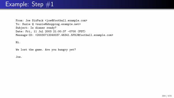
Example: Step #1
From: Joe SixPack <[email protected]>
To: Suzie Q <[email protected]>
Subject: Is dinner ready?
Date: Fri, 11 Jul 2003 21:00:37 -0700 (PDT)
Message-ID: <[email protected]>
Hi.
We lost the game. Are you hungry yet?
Joe.
394 / 470

Example: Step #2
DKIM-Signature: v=1; a=rsa-sha256; s=brisbane; d=example.com;
c=simple/simple; q=dns/txt; [email protected];
h=Received : From : To : Subject : Date : Message-ID;
bh=2jUSOH9NhtVGCQWNr9BrIAPreKQjO6Sn7XIkfJVOzv8=;
b=AuUoFEfDxTDkHlLXSZEpZj79LICEps6eda7W3deTVFOk4yAUoqOB
4nujc7YopdG5dWLSdNg6xNAZpOPr+kHxt1IrE+NahM6L/LbvaHut
KVdkLLkpVaVVQPzeRDI009SO2Il5Lu7rDNH6mZckBdrIx0orEtZV
4bmp/YzhwvcubU4=;
Received: from client1.football.example.com [192.0.2.1]
by submitserver.example.com with SUBMISSION;
Fri, 11 Jul 2003 21:01:54 -0700 (PDT)
From: Joe SixPack <[email protected]>
To: Suzie Q <[email protected]>
Subject: Is dinner ready?
Date: Fri, 11 Jul 2003 21:00:37 -0700 (PDT)
Message-ID: <[email protected]>
Hi.
We lost the game. Are you hungry yet?
Joe.395 / 470

Example: Step #3
X-Authentication-Results: shopping.example.net
[email protected]; dkim=pass
Received: from mout23.football.example.com (192.168.1.1)
by shopping.example.net with SMTP;
Fri, 11 Jul 2003 21:01:59 -0700 (PDT)
DKIM-Signature: v=1; a=rsa-sha256; s=brisbane; d=example.com;
c=simple/simple; q=dns/txt; [email protected];
h=Received : From : To : Subject : Date : Message-ID;
bh=2jUSOH9NhtVGCQWNr9BrIAPreKQjO6Sn7XIkfJVOzv8=;
b=AuUoFEfDxTDkHlLXSZEpZj79LICEps6eda7W3deTVFOk4yAUoqOB
4nujc7YopdG5dWLSdNg6xNAZpOPr+kHxt1IrE+NahM6L/LbvaHut
KVdkLLkpVaVVQPzeRDI009SO2Il5Lu7rDNH6mZckBdrIx0orEtZV
4bmp/YzhwvcubU4=;
Received: from client1.football.example.com [192.0.2.1]
by submitserver.example.com with SUBMISSION;
Fri, 11 Jul 2003 21:01:54 -0700 (PDT)
From: Joe SixPack <[email protected]>
To: Suzie Q <[email protected]>
Subject: Is dinner ready?
Date: Fri, 11 Jul 2003 21:00:37 -0700 (PDT)
Message-ID: <[email protected]>
Hi.
We lost the game. Are you hungry yet?
Joe.
396 / 470

References I
R. Housley.
Cryptographic Message Syntax (CMS).RFC 3852, Vigil Security, July 2004.
J. Klensin.
Simple Mail Transfer Protocol.RFC 5321, October 2008.
P. Resnick.
Internet Message Format.RFC 5322, QUALCOMM Incorporated, October 2008.
N. Freed and N. Borenstein.
Multipurpose Internet Mail Extensions (MIME) Part One: Format of Internet Message Bodies.RFC 2045, Innosoft, First Virtual, November 1996.
N. Freed and N. Borenstein.
Multipurpose Internet Mail Extensions (MIME) Part Two: Media Types.RFC 2046, Innosoft, First Virtual, November 1996.
M. Crispin.
Internet Message Access Protocol -Version 4rev1.RFC 3501, University of Washington, March 2003.
P. Guenther and T. Showalter.
Sieve: A Mail Filtering Language.RFC 5228, Sendmail Inc., Mirapoint Inc., January 2008.
397 / 470

References II
W. Segmuller and B. Leiba.
Sieve Email Filtering: Relational Extensions.RFC 5231, IBM T.J. Watson Research Center, January 2008.
C. Daboo.
Sieve Email Filtering: Spamtest and Virustest Extensions.RFC 5235, January 2008.
J. Degener.
Sieve Extension: Copying Without Side Effects.RFC 3894, Sendmail, October 2004.
S. Josefsson.
The Base16, Base32, and Base64 Data Encodings.RFC 4648, SJD, October 2006.
J. Callas, L. Donnerhacke, H. Finney, D. Shaw, and R. Thayer.
OpenPGP Message Format.RFC 4880, PGP Corporation, IKS GmbH, November 2007.
B. Ramsdell.
Secure/Multipurpose Internet Mail Extensions (S/MIME) Version 3.1 Message Specification.RFC 3851, Sendmail, Inc., July 2004.
E. Allman, J. Callas, M. Delany, M. Libbey, J. Fenton, and M. Thomas.
DomainKeys Identified Mail (DKIM) Signatures.RFC 4871, Sendmail Inc., PGP Corporation, Yahoo! Inc., Cisco Systems Inc., May 2007.
398 / 470

Part: Hypertext Transfer Protocol (HTTP)
45 Overview
46 URLs, URNs, URIs, IRIs
47 HTTP Methods
48 HTTP 1.1 Features
399 / 470

Overview
45 Overview
46 URLs, URNs, URIs, IRIs
47 HTTP Methods
48 HTTP 1.1 Features
400 / 470

Hypertext Transfer Protocol (HTTP)
The Hypertext Transfer Protocol (HTTP) version 1.1 is defined in RFC2616 is one of the core building blocks of the World Wide Web.
HTTP is primarily used to exchange documents between clients (browsers)and servers.
The HTTP protocol runs on top of TCP and it uses the well known portnumber 80.
HTTP utilizes MIME conventions in order to distinguish different mediatypes.
RFC 2817 describes how to use TLS with HTTP 1.1.
The Common Gateway Interface described in RFC 3875 allows to implementsimple dynamic web pages.
401 / 470

URLs, URNs, URIs, IRIs
45 Overview
46 URLs, URNs, URIs, IRIs
47 HTTP Methods
48 HTTP 1.1 Features
402 / 470

URL, URI, URN, IRI, . . .
Uniform Resource Identifier (URI)A URI is a sequence of characters from the US-ASCII for identifying anabstract or physical resource.
Uniform Resource Locator (URL)The term URL refers to the subset of URIs that provide a means of locatingthe resource by describing its primary access mechanism (e.g., its network”location”).
Uniform Resource Name (URN)The term URN refer to the subset of URIs that identify resources by meansof a globally unique and persistent name.
Internationalized Resource Identifier (IRI)An IRI is a sequence of characters from the Universal Character Set foridentifying an abstract or physical resource.
403 / 470

URI Syntax in ABNF
URI = scheme ":" hier-part [ "?" query ] [ "#" fragment ]
hier-part = "//" authority path-abempty
/ path-absolute
/ path-rootless
/ path-empty
URI-reference = URI / relative-ref
absolute-URI = scheme ":" hier-part [ "?" query ]
relative-ref = relative-part [ "?" query ] [ "#" fragment ]
relative-part = "//" authority path-abempty
/ path-absolute
/ path-noscheme
/ path-empty
scheme = ALPHA *( ALPHA / DIGIT / "+" / "-" / "." )
404 / 470

URI Syntax in ABNF
authority = [ userinfo "@" ] host [ ":" port ]
userinfo = *( unreserved / pct-encoded / sub-delims / ":" )
host = IP-literal / IPv4address / reg-name
port = *DIGIT
IP-literal = "[" ( IPv6address / IPvFuture ) "]"
IPvFuture = "v" 1*HEXDIG "." 1*( unreserved / sub-delims / ":" )
IPv6address = 6( h16 ":" ) ls32
/ "::" 5( h16 ":" ) ls32
/ [ h16 ] "::" 4( h16 ":" ) ls32
/ [ *1( h16 ":" ) h16 ] "::" 3( h16 ":" ) ls32
/ [ *2( h16 ":" ) h16 ] "::" 2( h16 ":" ) ls32
/ [ *3( h16 ":" ) h16 ] "::" h16 ":" ls32
/ [ *4( h16 ":" ) h16 ] "::" ls32
/ [ *5( h16 ":" ) h16 ] "::" h16
/ [ *6( h16 ":" ) h16 ] "::"
405 / 470

URI Syntax in ABNF
h16 = 1*4HEXDIG
ls32 = ( h16 ":" h16 ) / IPv4address
IPv4address = dec-octet "." dec-octet "." dec-octet "." dec-octet
dec-octet = DIGIT ; 0-9
/ %x31-39 DIGIT ; 10-99
/ "1" 2DIGIT ; 100-199
/ "2" %x30-34 DIGIT ; 200-249
/ "25" %x30-35 ; 250-255
reg-name = *( unreserved / pct-encoded / sub-delims )
path = path-abempty ; begins with "/" or is empty
/ path-absolute ; begins with "/" but not "//"
/ path-noscheme ; begins with a non-colon segment
/ path-rootless ; begins with a segment
/ path-empty ; zero characters
406 / 470

URI Syntax in ABNF
path-abempty = *( "/" segment )
path-absolute = "/" [ segment-nz *( "/" segment ) ]
path-noscheme = segment-nz-nc *( "/" segment )
path-rootless = segment-nz *( "/" segment )
path-empty = 0<pchar>
segment = *pchar
segment-nz = 1*pchar
segment-nz-nc = 1*( unreserved / pct-encoded / sub-delims / "@" )
pchar = unreserved / pct-encoded / sub-delims / ":" / "@"
query = *( pchar / "/" / "?" )
fragment = *( pchar / "/" / "?" )
pct-encoded = "%" HEXDIG HEXDIG
unreserved = ALPHA / DIGIT / "-" / "." / "_" / "~"
reserved = gen-delims / sub-delims
gen-delims = ":" / "/" / "?" / "#" / "[" / "]" / "@"
sub-delims = "!" / "$" / "&" / "’" / "(" / ")"
/ "*" / "+" / "," / ";" / "="
407 / 470

HTTP Methods
45 Overview
46 URLs, URNs, URIs, IRIs
47 HTTP Methods
48 HTTP 1.1 Features
408 / 470

HTTP 1.1 Methods
OPTIONS
Request information about the communication options available
GET
Retrieve whatever information is identified by a URI
HEAD
Retrieve only the meta-information which is identified by a URI
POST
Annotate an existing resource or pass data to a data-handling process
409 / 470

HTTP 1.1 Methods (cont.)
PUT
Store information under the supplied URI
DELETE
Delete the resource identified by the URI
TRACE
Application-layer loopback of request messages for testing purposes
CONNECT
Initiate a tunnel such as a TLS or SSL tunnel
410 / 470

HTTP 1.1 ABNF
Message = Request / Response
Request = Request-Line *(message-header CRLF) CRLF [ message-body ]
Response = Status-Line *(message-header CRLF) CRLF [ message-body ]
Request-Line = Method SP Request-URI SP HTTP-Version CRLF
Status-Line = HTTP-Version SP Status-Code SP Reason-Phrase CRLF
Method = "OPTIONS" / "GET" / "HEAD" / "POST"
Method =/ "PUT" / "DELETE" / "TRACE" / "CONNECT"
Method =/ Extension-Method
Extension-Method = token
411 / 470

HTTP 1.1 ABNF (cont.)
Request-URI = "*" | absoluteURI | abs_path | authority
HTTP-Version = "HTTP" "/" 1*DIGIT "." 1*DIGIT
Status-Code = 3DIGIT
Reason-Phrase = *<TEXT, excluding CR, LF>
message-header = field-name ":" [ field-value ]
field-name = token
field-value = *( field-content / LWS )
field-content = <the OCTETs making up the field-value
and consisting of either *TEXT or combinations
of token, separators, and quoted-string>
412 / 470

HTTP 1.1 Features
45 Overview
46 URLs, URNs, URIs, IRIs
47 HTTP Methods
48 HTTP 1.1 Features
413 / 470

Persistent Connections and Pipelining
A client can establish a persistent connection to a server and use it to sendmultiple Request messages.
HTTP relies on the MIME Content-Length header field to detect the endof a message body (document).
Early HTTP versions allowed only a single Request/Response exchangeover a single TCP connection, which is of course rather expensive.
HTTP 1.1 also allows clients to make multiple requests without waiting foreach response (pipelining), which can significantly reduce latency.
414 / 470

Caching and Proxies
Probably the most interesting and also most complex part of HTTP is itssupport for proxies and caching.
Proxies are entities that exist between the client and the server and whichbasically relay requests and responses.
Some proxies and clients maintain caches where copies of documents arestored in local storage space to speedup future accesses to these cacheddocuments.
The HTTP protocol allows a client to interrogate the server to determinewhether the document has changed or not.
Not all problems related to HTTP proxies and caches have been solved. Agood list of issues can be found in RFC 3143.
415 / 470

Negotiation
Negotation can be used to select different document formats, differenttransfer encodings, different languages or different character sets.
Server-driven negotiation begins with a request from a client (a browser).The client indicates a list of its preferences. The server then decides how tobest respond to the request.
Client-driven negotiation requires two requests. The client first asks theserver what is available and then decides which concrete request to send tothe server.
In most cases, server-driven negotiation is used since this is much moreefficient.
416 / 470

Negotiation Example
The following is an example of typical negotiation header lines:Accept: text/xml, application/xml, text/html;q=0.9, text/plain;q=0.8
Accept-Language: de, en;q=0.5
Accept-Encoding: gzip, deflate, compress;q=0.9
Accept-Charset: ISO-8859-1, utf8;q=0.66, *;q=0.33
The first line indicates that the client accepts text/xml, application/xml,and text/plain and that it prefers text/html over text/plain.
The last line indicates that the client prefers ISO-8859-1 encoding (withpreference 1), UTF8 encoding with preference 0.66 and any other encodingwith preference 0.33.
417 / 470

Conditional Requests
Clients can make conditional requests by including headers that qualify theconditions under which the request should be honored.
Conditional requests can be used to avoid unnecessary requests (e.g., tovalidate cached data).
Example:If-Modified-Since: Wed, 26 Nov 2003 23:21:08 +0100
The server checks whether the document was changed after the dateindicated by the header line and only process the request if this is the case.
418 / 470

Other Features and Extensions
Delta Encoding (RFC 3229)
A mechanism to request only the document changes relative to a specificversion.
Web Distributed Authoring (RFC 2518, RFC 3253)
An extension to the HTTP/1.1 protocol that allows clients to performremote web content authoring operations.
HTTP as a Substrate (RFC 3205)
HTTP is sometimes used as a substrate for other application protocols (e.g.,IPP or SOAP).There are some pitfalls with this approach as documented in RFC 3205.
419 / 470

References I
R. Fielding, J. Gettys, J. Mogul, H. Frystyk, L. Masinter, P. Leach, and T. Berners-Lee.
Hypertext Transfer Protocol – HTTP/1.1.RFC 2616, UC Irvine, Compaq/W3C, Compaq, W3C/MIT, Xerox, Microsoft, W3C/MIT, June 1999.
R. Khare and S. Lawrence.
Upgrading to TLS Within HTTP/1.1.RFC 2817, 4K Associates / UC Irvine, Agranat Systems, May 2001.
E. Rescorla.
HTTP Over TLS.RFC 2818, RTFM, May 2000.
D. Robinson and K. Coar.
The Common Gateway Interface (CGI) Version 1.1.RFC 3875, Apache Software Foundation, October 2004.
J. Mogul, B. Krishnamurthy, F. Douglis, A. Feldmann, Y. Goland, A. van Hoff, and D. Hellerstein.
Delta encoding in HTTP.RFC 3229, Compaq WRL, AT&T, Univ. of Saarbruecken, Marimba, ERS/USDA, January 2002.
Y. Goland, E. Whitehead, A. Faizi, S. Carter, and D. Jensen.
HTTP Extensions for Distributed Authoring – WEBDAV.RFC 2518, Microsoft, UC Irvine, Netscape, Novell, February 1999.
420 / 470

References II
G. Clemm, J. Amsden, T. Ellison, C. Kaler, and J. Whitehead.
Versioning Extensions to WebDAV (Web Distributed Authoring and Versioning).RFC 3253, Rational Software, IBM, Microsoft, U.C. Santa Cruz, March 2002.
K. Moore.
On the use of HTTP as a Substrate.RFC 3205, University of Tennessee, February 2002.
421 / 470

Part: File Transfer Protocol
422 / 470

File Transfer Protocol (FTP)
FTP Server FTP Client
data transferprocess
processcontrol
filesystem
data transferprocess
filesystem
processcontrol
interfaceuser
commands
replies
data
The FTP protocol defined in RFC 959 uses a separate TCP connection foreach data transfer.
This approach sidesteps any problems about marking the end of files.
423 / 470

File Transfer Protocol (FTP)
The control connection uses a text-based line-oriented protocol which issimilar to SMTP.
The client sends commands which are processed by the server. The serversends responses using three digit response codes.
If the data transfer connection is initiated by the server, then the client’sport number must be conveyed first to the server.
If the data transfer connection is initiated by the client, then the well-knownport number 20 is used. The well-known port number for the controlconnection is 21.
424 / 470

File Transfer Protocol (FTP)
FTP allows to resume a data transmission that did not complete using aspecial restart mechanism.
FTP can be used to initiate a data transfer between two remote systems.However, this feature of FTP can result in some interesting securityproblems (see RFC 2577 for more details).
RFC 2228 defines security extensions for FTP (authentication, integrity andconfidentiality).
RFC 4217 defines how to run FTP over TLS.
425 / 470

FTP Commands
USER <SP> <username> <CRLF>
PASS <SP> <password> <CRLF>
ACCT <SP> <account-information> <CRLF>
CWD <SP> <pathname> <CRLF>
CDUP <CRLF>
SMNT <SP> <pathname> <CRLF>
QUIT <CRLF>
REIN <CRLF>
PORT <SP> <host-port> <CRLF>
PASV <CRLF>
TYPE <SP> <type-code> <CRLF>
STRU <SP> <structure-code> <CRLF>
MODE <SP> <mode-code> <CRLF>
RETR <SP> <pathname> <CRLF>
426 / 470

FTP Commands
STOR <SP> <pathname> <CRLF>
STOU <CRLF>
APPE <SP> <pathname> <CRLF>
ALLO <SP> <decimal-integer>
[<SP> R <SP> <decimal-integer>] <CRLF>
REST <SP> <marker> <CRLF>
RNFR <SP> <pathname> <CRLF>
RNTO <SP> <pathname> <CRLF>
ABOR <CRLF>
DELE <SP> <pathname> <CRLF>
RMD <SP> <pathname> <CRLF>
MKD <SP> <pathname> <CRLF>
PWD <CRLF>
427 / 470

FTP Commands
LIST [<SP> <pathname>] <CRLF>
NLST [<SP> <pathname>] <CRLF>
SITE <SP> <string> <CRLF>
SYST <CRLF>
STAT [<SP> <pathname>] <CRLF>
HELP [<SP> <string>] <CRLF>
NOOP <CRLF>
428 / 470

FTP Command Parameters
<username> ::= <string>
<password> ::= <string>
<account-information> ::= <string>
<string> ::= <char> | <char><string>
<char> ::= any of the 128 ASCII characters
except <CR> and <LF>
<marker> ::= <pr-string>
<pr-string> ::= <pr-char> | <pr-char><pr-string>
<pr-char> ::= printable characters, any ASCII
code 33 through 126
<byte-size> ::= <number>
<host-port> ::= <host-number>,<port-number>
429 / 470

FTP Command Parameters
<host-number> ::= <number>,<number>,<number>,<number>
<port-number> ::= <number>,<number>
<number> ::= any decimal integer 1 through 255
<form-code> ::= N | T | C
<type-code> ::= A [<sp> <form-code>]
| E [<sp> <form-code>]
| I
| L <sp> <byte-size>
<structure-code> ::= F | R | P
<mode-code> ::= S | B | C
<pathname> ::= <string>
<decimal-integer> ::= any decimal integer
430 / 470

References
J. Postel and J. Reynolds.
File Transfer Protocol (FTP).RFC 959, ISI, October 1985.
M. Horowitz and S. Lunt.
FTP Security Extensions.RFC 2228, Cygnus Solutions, Bellcore, October 1997.
M. Allman, S. Ostermann, and C. Metz.
FTP Extensions for IPv6 and NATs.RFC 2428, NASA Lewis/Sterling Software, Ohio University, The Inner Net, September 1998.
P. Ford-Hutchinson.
Securing FTP with TLS.RFC 4217, IBM UK Ltd, October 2005.
431 / 470

Part: Appendix
432 / 470

Part: Fundamental Network Concepts
49 Media Access Control
50 Transmission Error Detection
51 Sequence Numbers, Acknowledgements, Timer
52 Flow Control and Congestion Control
53 OSI Reference Model
433 / 470

Media Access Control
49 Media Access Control
50 Transmission Error Detection
51 Sequence Numbers, Acknowledgements, Timer
52 Flow Control and Congestion Control
53 OSI Reference Model
434 / 470

Media Access
fixed raster
time division multiplexing
media access
dynamic
decentralized centralized
concurrent ordered
frequency division multiplexing
Shared transmission media require coordinated access to the medium (mediaaccess control)
435 / 470

Frequency Division Multiplexing (FDM)
������������������������������������������������������������������������
������������������������������������������������������������������������
������������������������������������������������������������������������
������������������������������������������������������������������������
������������������������������������������������������������������������������������������������
������������������������������������������������������������������������������������������������
channel 1
channel 2
channel 3
channel 4
channel 5
time
frequency
Signals are carried simultaneously on the same medium by allocating to eachsignal a different frequency band
436 / 470

Wavelength Division Multiplexing (WDM)
Optical fibers carry multiple wavelength at the same time
WDM can achieve very high data rates over a single optical fiber
Dense WDM (DWDM) is a variation where the wavelengths are spaced closetogether, which results in an even larger number of channels.
Theoretically, there is room for 1250 channels, each running at 10 Gbps, ona single fiber (= 12.5 Tbps).
A single cable often bundles a number of fibers and for deployment orreasons, fibres are sometimes even bundled with power cables.
437 / 470

Time Division Multiplexing (TDM)
������������������������
������������������������
������������������������
������������������������
������������������������������������������������
������������������������������������������������
������������������������������������������������
������������������������������������������������
������������������������������������������������
������������������������������������������������
������������������������
������������������������
������������������������
������������������������
������������������������
������������������������
������������������������������������������������
������������������������������������������������
frequency
chan
nel
1
chan
nel
3
chan
nel
...
chan
nel
n
chan
nel
2
time
chan
nel
1
chan
nel
2
chan
nel
3
chan
nel
...
chan
nel
n
Signals from a given sources are assigned to specific time slots
Time slot assignment might be fixed (synchronous TDM) or dynamic(statistical TDM)
438 / 470

Pure Aloha
���������
���������
����������������
���������
���������
������������
����������������
������������
������������
Station A:
Station B:
Station C:
time
Developed in the 1970s at the University of Hawaii
Sender sends data as soon as data becomes available
Collisions are detected by listening to the signal
Retransmit after a random pause after a collision
Not very efficient (≈ 18 % of the channel capacity)
439 / 470

Slotted Aloha
���������
���������
������������
������������
������������Station A:
Station B:
Station C:
time
Senders do not send immediately but wait for the beginning of a time slot
Time slots may be advertised by short control signals
Collisions only happen at the start of a transmission
Avoids sequences of partially overlaying data blocks
Slightly more efficient (≈ 37 % of the channel capacity)
440 / 470

Carrier Sense Multiple Access (CSMA)
������������
������������
���������
���������
������������
Station A:
Station B:
Station C:
time
Sense the media whether it is unused before starting a transmission
Collisions are still possible (but less likely)
1-persistent CSMA: sender sends with probability 1
p-persistent CSMA: sender sends with probability p
non-persistent CSMA: sender waits for a random time period before itretries if the media is busy
441 / 470
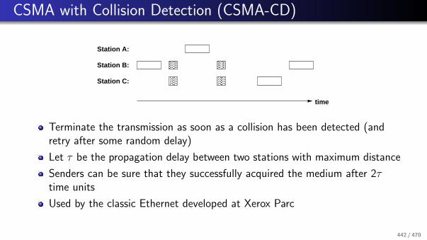
CSMA with Collision Detection (CSMA-CD)
����
���
���
��������
������
������
Station A:
Station B:
Station C:
time
Terminate the transmission as soon as a collision has been detected (andretry after some random delay)
Let τ be the propagation delay between two stations with maximum distance
Senders can be sure that they successfully acquired the medium after 2τtime units
Used by the classic Ethernet developed at Xerox Parc
442 / 470

Multiple Access with Collision Avoidance (MACA)
B−>C
Station A:
Station B:
Station C:
CTS
RTS
time
B−>C C−>B C−>B B−>C C−>B
A station which is ready to send first sends a short RTS (ready to send)message to the receiver
The receiver responds with a short CTS (clear to send) message
Stations who receive RTS or CTS must stay quiet
Solves the hidden station and exposed station problem
443 / 470

Token
Station A:
Station B:
Station C:
time
A token is a special bit pattern circulating between stations - only thestation holding the token is allowed to send data
Token mechanisms naturally match physical ring topologies - logical ringsmay be created on other physical topologies
Care must be taken to handle lost or duplicate token
444 / 470

Transmission Error Detection
49 Media Access Control
50 Transmission Error Detection
51 Sequence Numbers, Acknowledgements, Timer
52 Flow Control and Congestion Control
53 OSI Reference Model
445 / 470

Transmission Error Detection
Data transmission often leads to transmission errors that affect one or morebits
Simple parity bits can be added to code words to detect bit errors
Parity bit schemes are not very strong in detecting errors which affectmultiple bits
Computation of error check codes must be efficient (in hardware and/orsoftware)
446 / 470

Cyclic Redundancy Check (CRC)
A bit sequence (bit block) bnbn−1 . . . b1b0 is represented as a polynomialB(x) = bnxn + bn−1xn−1 + . . . + b1x + b0
Arithmetic operations:
0 + 0 = 1 + 1 = 0 1 + 0 = 0 + 1 = 1
1 · 1 = 1 0 · 0 = 0 · 1 = 1 · 0 = 0
A generator polynomial G (x) = grxr + . . . g1x + g0 with gr = 1 and g0 = 1
is agreed upon between the sender and the receiver
The sender transmits U(x) = x r · B(x) + t(x) with
t(x) = (x r · B(x)) mod G (x)
447 / 470

Cyclic Redundancy Check (CRC)
The receiver tests whether the polynomial corresponding to the received bitsequence can be divided by G (x) without a remainder
Efficient hardware implementation possible using XOR gates and shiftregisters
Only errors divisible by G (x) will go undetected
Example:
Generator polynomial G (x) = x3 + x2 + 1(corresponds to the bit sequence 1101)Message M = 1001 1010(corresponds to the polynomial B(x) = x7 + x4 + x3 + x)
448 / 470

CRC Computation
1001 1010 000 : 1101
1101
----
100 1
110 1
-----
10 00
11 01
-----
1 011
1 101
-----
1100
1101
----
1 000
1 101
-----
101 => transmitted bit sequence 1001 1010 101
449 / 470

CRC Verification
1001 1010 101 : 1101
1101
----
100 1
110 1
-----
10 00
11 01
-----
1 011
1 101
-----
1100
1101
----
1 101
1 101
-----
0 => remainder 0, assume no transmission error
450 / 470

Choosing Generator Polynomials
G (x) detects all single-bit errors if G (x) has more than one non-zero term
G (x) detects all double-bit errors, as long as G (x) has a factor with threeterms
G (x) detects any odd number of errors, as long as G (x) contains the factor(x + 1)
G (x) detects any burst errors for which the length of the burst is less thanor equal to r
G (x) detects a fraction of error bursts of length r + 1; the fraction equals to1− 2−(r−1)
G (x) detects a fraction of error bursts of length greater than r + 1; thefraction equals to 1− 2−r
451 / 470

Well-known Generator Polynomials
The HEC polynomial G (x) = x8 + x2 + x + 1 is used by the ATM cell header
The CRC-16 polynomial G (x) = x16 + x15 + x2 + 1 detects all single anddouble bit errors, all errors with an odd number of bits, all burst errors with16 or less bits and more than 99% of all burst errors with 17 or more bits
The CRC-CCITT polynomial G (x) = x16 + x15 + x5 + 1 is used by theHDLC protocol
The CRC-32 polynomialG (x) = x32+x26+x23+x22+x16+x12+x11+x10+x8+x7+x5+x4+x2+x +1is used by the IEEE 802 standards
452 / 470

Internet Checksum
uint16_t
checksum(uint16_t *buf, int count)
{
uint32_t sum = 0;
while (count--) {
sum += *buf++;
if (sum & 0xffff0000) {
sum &= 0xffff;
sum++;
}
}
return ~(sum & 0xffff);
}
453 / 470

Internet Checksum Properties
Summation is commutative and associative
Computation independent of the byte order
Computation can be parallelized on processors with word sizes larger than 16bit
Individual data fields can be modified without having to recompute thewhole checksum
Can be integrated into copy loop
Often implemented in assembler or special hardware
For details, see RFC 1071, RFC 1141, and RFC 1624
454 / 470

Further Error Situations
Despite bit errors, the following transmission errors can occur
Loss of complete data framesDuplication of complete data framesReceipt of data frames that were never sentReordering of data frames during transmission
In addition, the sender must adapt its speed to the speed of the receiver(end-to-end flow control)
Finally, the sender must react to congestion situations in the network(congestion control)
455 / 470

Sequence Numbers, Acknowledgements, Timer
49 Media Access Control
50 Transmission Error Detection
51 Sequence Numbers, Acknowledgements, Timer
52 Flow Control and Congestion Control
53 OSI Reference Model
456 / 470

Sequence Numbers
The sender assigns growingsequence numbers to all dataframes
A receiver can detect reordered orduplicated frames
Loss of a frame can be determinedif a missing frame cannot travel inthe network anymore
Sequence numbers can growquickly on fast networks
sender
1
2
3
4
5
6
7
8
1
3
4
6
5
4
7
8
receiver
457 / 470

Acknowledgements
Retransmit to handle errors
A positive acknowledgement (ACK)is sent to inform the sender thatthe transmission of a frame wassuccessful
A negative acknowledgement(NACK) is sent to inform thesender that the transmission of aframe was unsuccessful
Stop-and-wait protocol: a frame isonly transmitted if the previousframe was been acknowledged
sender
n
ACK n
n+1
n+1 (error)
ACK n
NACK n+1
n+1
n+1
ACK n+1
ACK n+1
NACK n+1
n
receiver
458 / 470

Timers
Timer can be used to detect theloss of frames or acknowledgments
A sender can use a timer toretransmit a frame if noacknowledgment has been receivedin time
A receiver can use a timer toretransmit acknowledgments
Problem: Timers must adapt to thecurrent delay in the network
sender
n
nACK n
nACK n
ACK n
n
n+1
n+1
n+1ACK n+1
ACK n+1
receiver
459 / 470

Flow Control and Congestion Control
49 Media Access Control
50 Transmission Error Detection
51 Sequence Numbers, Acknowledgements, Timer
52 Flow Control and Congestion Control
53 OSI Reference Model
460 / 470

Flow Control
Allow the sender to send multipleframes before waiting foracknowledgments
Improves efficiency and overall delay
Sender must not overflow thereceiver
The stream of frames should besmooth and not bursty
Speed of the receiver can vary overtime
n+0
n+0ACK n+0
ACK n+3
ACK n+3
n+3
n+6
n+6ACK n+6
ACK n+6
n+1
n+2
n+4
n+1
n+3
n+2ACK n+1
ACK n+2ACK n+1
ACK n+2
ACK n+0
n+5
n+6
n+4
n+5ACK n+5n+6ACK n+6n+4ACK n+4
n+7
n+8
n+9
n+7
n+8
n+9
ACK n+7
ACK n+8
ACK n+9
ACK n+4
ACK n+7
ACK n+8
ACK n+9
ACK n+5
sender receiver
461 / 470

Sliding Window Flow Control
Sender and receiver agree on a window of the sequence number space
The sender may only transmit frames whose sequence number falls into thesender’s window
Upon receipt of an acknowledgement, the sender’s window is moved
The receiver only accepts frames whose sequence numbers fall into thereceiver’s window
Frames with increasing sequence number are delivered and the receiverwindow is moved.
The size of the window controls the speed of the sender and must match thebuffer capacity of the receiver
462 / 470

Sliding Window Implementation
Implementation on the sender side:
SWS (send window size)LAR (last ack received)LFS (last frame send)Invariant: LFS - LAR + 1 ≤ SWS
Implementation on the receiver side:
RWS (receiver window size)LFA (last frame acceptable)NFE (next frame expected)Invariant: LFA - NFE + 1 ≤ RWS
463 / 470

Congestion Control
Flow control is used to adapt the speed of the sender to the speed of thereceiver
Congestion control is used to adapt the speed of the sender to the speed ofthe network
Principles:
Sender and receiver reserve bandwidth and puffer capacity in the networkIntermediate systems drop frames under congestion and signal the event tothe senders involvedIntermediate systems send control messages (choke packets) whencongestion builds up to slow down senders
464 / 470

OSI Reference Model
49 Media Access Control
50 Transmission Error Detection
51 Sequence Numbers, Acknowledgements, Timer
52 Flow Control and Congestion Control
53 OSI Reference Model
465 / 470

OSI Reference Model
End System
Physical
Data Link
Transport
Session
Presentation
Application
Transport
Physical
Data Link
Network Network
Media Media
Application Process
Ap
licat
ion
Sys
tem
Tra
nsp
ort
Sys
tem
Application Process
End System
Tran
spo
rt System
Ap
plicatio
n S
ystem
Application
Presentation
Session
Network
Data Link
Physical
Transit System
466 / 470

Physical and Data Link Layer
Physical Layer:
Transmission of an unstructured bit streamStandards for cables, connectors and socketsEncoding of binary values (voltages, frequencies)Synchronization between sender and receiver
Data Link Layer:
Transmission of bit sequences in so called framesData transfer between directly connected systemsDetection and correction of transmission errorsFlow control between senders and receiversRealization usually in hardware
467 / 470

Network and Transport Layer
Network Layer:
Determination of paths through a complex networkMultiplexing of end-to-end connections over an intermediate systemsError detection / correction between network nodesFlow and congestion control between end systemsTransmission of datagrams or packets in packet switched networks
Transport Layer:
Reliable end-to-end communication channelsConnection-oriented and connection-less servicesEnd-to-end error detection and correctionEnd-to-end flow and congestion control
468 / 470

Session and Presentation Layer
Session Layer:
Synchronization and coordination of communicating processesInteraction control (check points)
Presentation Layer:
Harmonization of different data representationsSerialization of complex data structuresData compression
Application Layer:
Fundamental application oriented servicesTerminal emulationen, name and directory services, data base access,network management, electronic messaging systems, process and machinecontrol, . . .
469 / 470

References
J. F. Kurose and K. W. Ross.
Computer Networking: A Top-Down Approach Featuring the Internet.Addison-Wesley, 3 edition, 2004.
A. S. Tanenbaum.
Computer Networks.Prentice Hall, 4 edition, 2002.
J. Stone and C. Partridge.
When The CRC and TCP Checksum Disagree.In Proc. SIGCOMM 2000, pages 309–319, Stockholm, August 2000. ACM.
470 / 470