Nasa - Fully-Coupled Fluid-Structure Vibration Analysis Using Nastran

NAFEMS World Congress 2015 | 21-24 June | San Diego | California | USA
Coupled Facility/Payload Vibration Modeling Improvements
Timothy M. Carnahan NASA/GSFCMichael Kaiser ASRC
Goddard Space Flight Center
https://ntrs.nasa.gov/search.jsp?R=20150011493 2018-05-21T14:15:42+00:00Z

NAFEMS World Congress 2015 | 21-24 June | San Diego | California | USA

NAFEMS World Congress 2015 | 21-24 June | San Diego | California | USA
NASA/GSFC• NASA/Goddard Space Flight Center: Since 1959 has
designed, built, tested and flown hundreds of satellites, for Earth science, Space Science, communications and engineering demonstrations.– Recent satellites: MMS, GPM, LRO, SDO and more– Current satellites: JWST and IceSat2/ATLAS– Campus of 3250 civil servants on 1270 acres in Greenbelt
Maryland– Sciences and engineering work together to achieve advanced
technology missions using the latest technologies.– Code 500 Applied Engineering and Technical Division
• Code 540 Mechanical Services Directorate– Code 542 Mechanical Systems Analysis and Simulations Branch– Code 549 Environmental Test Engineering and Integration Branch

NAFEMS World Congress 2015 | 21-24 June | San Diego | California | USA
NAFEMS World Congress 2015 | 21-24 June | San Diego | California | USA
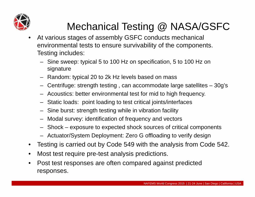
Mechanical Testing @ NASA/GSFC• At various stages of assembly GSFC conducts mechanical
environmental tests to ensure survivability of the components. Testing includes:– Sine sweep: typical 5 to 100 Hz on specification, 5 to 100 Hz on
signature– Random: typical 20 to 2k Hz levels based on mass– Centrifuge: strength testing , can accommodate large satellites – 30g’s– Acoustics: better environmental test for mid to high frequency.– Static loads: point loading to test critical joints/interfaces– Sine burst: strength testing while in vibration facility– Modal survey: identification of frequency and vectors– Shock – exposure to expected shock sources of critical components– Actuator/System Deployment: Zero G offloading to verify design
• Testing is carried out by Code 549 with the analysis from Code 542.• Most test require pre-test analysis predictions.• Post test responses are often compared against predicted
responses.
NAFEMS World Congress 2015 | 21-24 June | San Diego | California | USA

NAFEMS World Congress 2015 | 21-24 June | San Diego | California | USA
Pre/Post Test Analysis work for testing• Code 542 performs the majority of mechanical pre-test prediction
analysis using Nastran and other tools.• Inputs and response limits are derived from generalized
environment specifications, or launch vehicle specific.• Numerous cycles of Coupled Loads Analysis (CLA) with the launch
provider refine and develop the input specifications to a satellite, and the satellites sub-components.
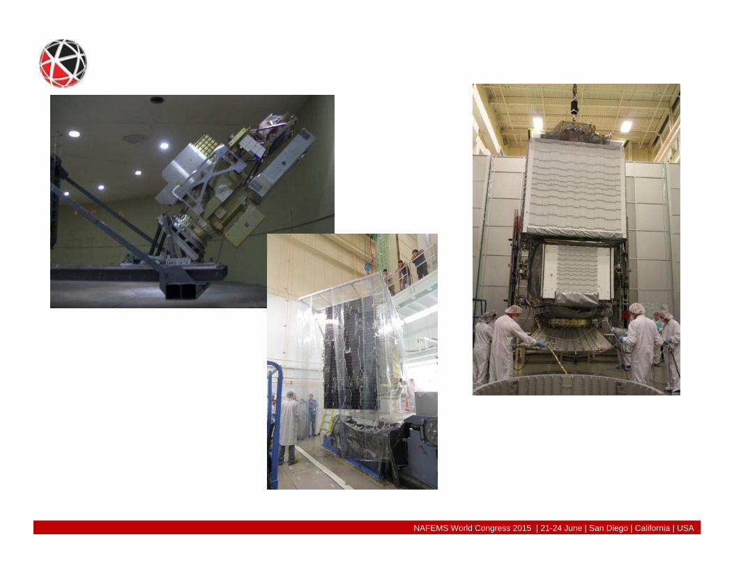
• A major component of the GPM satellite was the Solar Array Deployment and Drive Subsystem (SADDS).– Provided power to the satellite.– Deployed 2 wings with gimbaled ability to track the sun.– Tested at the component level prior to integration to the main
spacecraft.
Testing of flight components is usually schedule critical. Having a understanding of test responses keeps testing on schedule

NAFEMS World Congress 2015 | 21-24 June | San Diego | California | USA

NAFEMS World Congress 2015 | 21-24 June | San Diego | California | USA
GPM/SADDS Testing• Test levels where developed in conjunction with the
Launch Provider, Mitsubishi Heavy Industries, for their H2-A rocket for this subcomponent. Testing of the satellite would be the next major test using this facility for the GPM program.
• Mounted on a the Lower Bus Engineering Development Unit (EDU) of the GPM satellite, the SADDS system integrated to the GSFC shaker facility.
• Vibration Tests in the lateral configuration went well. The test article is well supported by a slip table.
Lateral test analysis has not yet shown to be predicting poorly correlated responses compared to test data.

NAFEMS World Congress 2015 | 21-24 June | San Diego | California | USA
SADDS crosstalk• During vertical testing of the SADDS system, excessive
crosstalk (out of input direction) was identified. This crosstalk was seen at the shaker input to the SADDS system, thus not a dynamic response from the test article.
• Control of the crosstalk meant notching the vertical input levels. If no notching was applied, crosstalk inputs to the test article would have exceeded testing performed in the lateral configuration. Furthermore, such levels would have exceeded margins and may have failed the structure.
• Pre-test analysis did not indicate any significant crosstalk would exist. What was the source of the crosstalk?
Vertical testing has historically had some poorly correlated test responses to analysis predictions for large test articles.
NAFEMS World Congress 2015 | 21-24 June | San Diego | California | USA
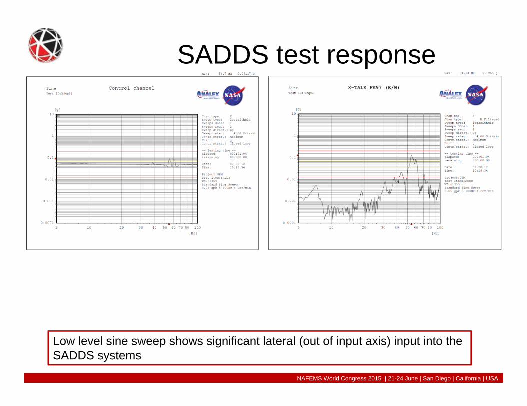
SADDS test response
Low level sine sweep shows significant lateral (out of input axis) input into the SADDS systems

NAFEMS World Congress 2015 | 21-24 June | San Diego | California | USA
NASA/GSFC Test facility• The GSFC vibration test facility mounts a shaker to a
seismic mass that is spring mounted to the foundation of the building. Use of a Guided Head Expander (GHE) has been added to the facility as needed to limit moment inputs into the shaker.
• Investigation was begun to identify the source of the crosstalk.

NAFEMS World Congress 2015 | 21-24 June | San Diego | California | USA
• Facility plots

NAFEMS World Congress 2015 | 21-24 June | San Diego | California | USA
The Shaker• The Shaker used at GSFC are Unholtz-Dickie T4000-2. They have
been in service for many years and are typical of many vibration test facilities. These are voice coil actuators with a flexures that guide axial motion and provide limited lateral restraint. Bearings in the base of the armature provide some over turning moment capability.
• GHE are used to further minimize the effect of overturning moment loads on the armature.
• Inertial masses, not used at GSFC at this time, can further mitigate the effect of an offset mass on the armature. However, the inertia mass may have to be substantial, which would create facility space issues and have limited resistance.
NAFEMS World Congress 2015 | 21-24 June | San Diego | California | USA
C-K Facility model• Carnahan-Kaiser model was developed to capture all the dynamics
of the test facility from the floor of the building to the test article. Stopping at the armature of the shaker proves to be incomplete with significant masses.
• Input loads are driven at the armature base and react against both the seismic mass and the test article. Lateral loads are coupled at the armature.
• This provides a better representation of the system dynamics then simply base driving the top of the armature, or alternative, displacement driving the test article with a large mass directly below. (Old school)
• Correlation tests where performed on a mass simulator and shown in the following slides. – Performed sine sweeps and random excitations identify system
behavior.• The crosstalk seen in the SADDS testing was now predictable and
expected.

NAFEMS World Congress 2015 | 21-24 June | San Diego | California | USA
C-K model drives input at the armature to shaker cbush. Reactions and coupling occur both above and below the drive point.

NAFEMS World Congress 2015 | 21-24 June | San Diego | California | USA
C-K Model correlation• Sine sweeps of the test mass (~3600Kg). Test article
included a test mass for the satellite and a Payload Attach Fitting (PAF) connected to the armature through a force ring with 8 load cells. The test mass and PAF were connected via a clamp band, commonly used to connect and separate satellites with the rocket.
• Test level the same as for the satellite.• Notching was in place to limit moment loads into the
clamp band.• Sine signatures were performed before and after all
major exposures. Sine signature frequency range was 1 to 150 Hz

NAFEMS World Congress 2015 | 21-24 June | San Diego | California | USA
In axis vertical test response
1.000E-02
1.000E-01
1.000E+00
1.000E+01
1.000E+02
1 10 100
Resp
onse
Frequency (Hz)
L8X+ -Z/+Y Top
Measured Transmissibility L8X+ Coupled Facility Analysis L8X+ Fixed Boundary Analysis L8X+
• Yellow is test data• Green is C-K model• Blue is classical (fixed base) model
NAFEMS World Congress 2015 | 21-24 June | San Diego | California | USA
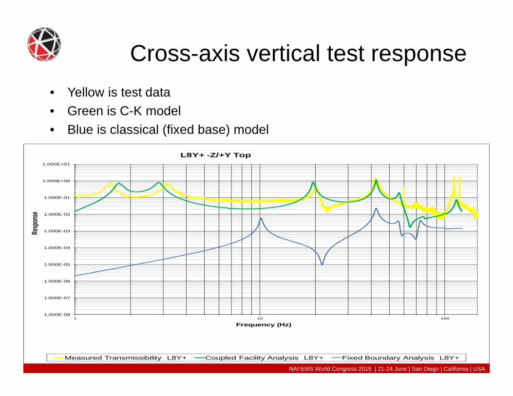
Cross-axis vertical test response
1.000E-08
1.000E-07
1.000E-06
1.000E-05
1.000E-04
1.000E-03
1.000E-02
1.000E-01
1.000E+00
1.000E+01
1 10 100
Resp
onse
Frequency (Hz)
L8Y+ -Z/+Y Top
Measured Transmissibility L8Y+ Coupled Facility Analysis L8Y+ Fixed Boundary Analysis L8Y+
• Yellow is test data• Green is C-K model• Blue is classical (fixed base) model

NAFEMS World Congress 2015 | 21-24 June | San Diego | California | USA
Cross-axis vertical test response• Yellow is test data• Green is C-K model• Blue is classical (fixed base) model
1.000E-08
1.000E-07
1.000E-06
1.000E-05
1.000E-04
1.000E-03
1.000E-02
1.000E-01
1.000E+00
1.000E+01
1 10 100
Resp
onse
Frequency (Hz)
L8Z+ -Z/+Y Top
Measured Transmissibility L8Z+ Coupled Facility Analysis L8Z+ Fixed Boundary Analysis L8Z+

NAFEMS World Congress 2015 | 21-24 June | San Diego | California | USA
Random vibration test of facility
• Random vibration tests where performed with a test mass of the satellite (~3600Kg)
• Test levels : 1 to 150 Hz at 0.2 G^2/Hz for 10 minutes.• Accelerometers mounted on the Shaker and the facility,
including the seismic mass.

NAFEMS World Congress 2015 | 21-24 June | San Diego | California | USA
• Video of Random test– This file could not be successfully embedded
and uploaded to the eDAA system. It can be found here:
– You have 30 days from 06-01-2015 to download the file(s) from the following URL:
• https://webdrive.gsfc.nasa.gov/longauth/500/jeffrey.a.bolognese/zz3AG4C
– Please use the following to download: • File Identifier: zWNEKIC3

NAFEMS World Congress 2015 | 21-24 June | San Diego | California | USA
Summary• One of the most important observations about the
coupled facility/payload tests is that for large payloads, the previously assumed fixed base assumption is generally incorrect for low-stiffness vertical shakers. The bending modes measured during the lateral test are not present during the vertical testing since the boundary flexibility makes the coupled system behave somewhere between a fixed and a free boundary. Interestingly for well centered structures with low coupling between bending and axial, the fixed base model under predicts the measured interface moments.
• C-K model was developed in support of the GPM satellite testing and allowed a successful test.

NAFEMS World Congress 2015 | 21-24 June | San Diego | California | USA
GPM satellite testing completed with well correlated test data responses to analysis predictions using the C-K model.
NAFEMS World Congress 2015 | 21-24 June | San Diego | California | USA
Future• Having developed this facility model for GPM it has been applied to
other programs at GSFC, including MMS and pre-test work for JWST. MMS data showed that the coupled facility model was a much better representation of the peak interface moments than fixed base predicts.
• Having a tool that improves the NASTRAN responses and correlates better with test is an advantage that will be used in future NASA/GSFC test predictions.
• When a satellite or major subsystem is tested and the response is not as expected there can be significant delays and concerns to completing the testing in a timely fashion. Thus having the C-K facility model is now viewed as a standard approach to vertical shaker testing in our current facilities for significant mass payloads.

NAFEMS World Congress 2015 | 21-24 June | San Diego | California | USA
Thanks• Global Precipitation Mission: Especially, Jay
Parker, Alexia Harper, Tim Schwartz, Art Azarbarzin, MHI and JAXA
• Very Special thanks to Michael Kaiser of ASRC for mechanical analysis work above and beyond.