Coupled Analysis of Mmotor to predict Noise and Vibration
18
Simulated. Designed. Delivered. Coupled analysis of motor to predict vibration and noise By Mr. Siddesh S Application Engineer ProSIM R&D Pvt. Ltd.
-
Upload
prosimrnd -
Category
Engineering
-
view
104 -
download
0
Transcript of Coupled Analysis of Mmotor to predict Noise and Vibration

Simulated. Designed. Delivered.
Coupled analysis of motor to predict vibration and noise
By
Mr. Siddesh S Application Engineer
ProSIM R&D Pvt. Ltd.
Simulated. Designed. Delivered. 2
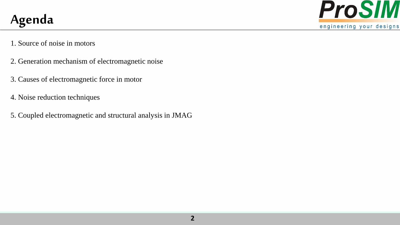
Agenda
1. Source of noise in motors
2. Generation mechanism of electromagnetic noise
3. Causes of electromagnetic force in motor
4. Noise reduction techniques
5. Coupled electromagnetic and structural analysis in JMAG
Simulated. Designed. Delivered. 3
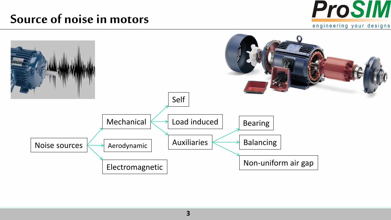
Noise sources Aerodynamic
Mechanical
Electromagnetic
Self
Load induced
Auxiliaries
Non-uniform air gap
Bearing
Balancing
Source of noise in motors

Simulated. Designed. Delivered. 4
Fundamental flux is superimposed with harmonics fields. MMF wave in the air gap causes attractive force and
tangential forces on stator core and teeth due to zigzag leakage permeance.
MMF distribution Magnetic flux wave distribution Electromagnetic force distibution
Generation mechanism of electromagnetic noise

Simulated. Designed. Delivered. 5
Electromagnetic force due to eccentricity
Distorted flux density
Causes of electromagnetic forces in Motor

Simulated. Designed. Delivered. 6
Skewing Rotor and stator slot shape Stator stack dimension Eccentricity
Manufacturing errors: tolerances, asymmetries
Materials
Noise reduction techniques

Simulated. Designed. Delivered. 7
It is important to know the frequencies at which the radial forces are produced and estimation of amplitude of radial magnetic
forces.
Magnetomotive force

www.pro-sim.com engineering your designs
Simulation Technology for Electromechanical Design
Coupled electromagnetic and structural analysis in JMAG
ProSIM R&D Pvt Ltd. #4, 1st B Main, 1st N Block, Rajajinagar, Bangalore – 560010
Ph: +91 80 23323020, Fax: +91 80 23323304, Website: www.pro-sim.com

Simulated. Designed. Delivered. 9
Structure of motor 2D Electromagnetic model
Electromagnetic force modeling

Simulated. Designed. Delivered. 10
Material specification

Simulated. Designed. Delivered. 11
Electromagnetic flux density distribution
Magnetic flux density distribution

Simulated. Designed. Delivered. 12
Electromagnetic force distribution Frequency component of electromagnetic force
Electromagnetic force distribution

Simulated. Designed. Delivered. 13
Constraint
Rotor mass
Rigid body
Rigid body
0.44kg Rotor mass
Boundary conditions for structural model

Simulated. Designed. Delivered. 14
Eigen mode deformation approximately at 3600 Hz
Eigen mode analysis
Simulated. Designed. Delivered. 15
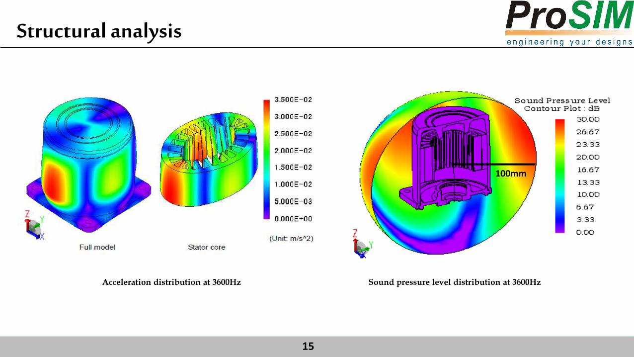
Acceleration distribution at 3600Hz
100mm
Sound pressure level distribution at 3600Hz
Structural analysis

Simulated. Designed. Delivered. 16
Conclusion
1. The electrical model, which accounts for the influence of mmf space harmonics and determines the air-gap radial
flux density, has been successfully analysed with FEM.
2. Numerical simulation allows in particular to virtually isolate the different sources of noise harmonics: winding
harmonics can be cancelled by imposing sinusoidal mmfs, PWM harmonics can be removed by imposing sinusoidal
currents, saturation harmonics by cancelling saturation permeance harmonics, slotting harmonics by imposing a
smooth air-gap, etc.

Simulated. Designed. Delivered. 17

Simulated. Designed. Delivered. 18
THANK YOU


![Ion-Hong Chao A Coupled Electromagnetic and …xlab.me.berkeley.edu/pdf/248.pdfwith 22nm half-pitch resolution have been demonstrated experi-mentally [5]. In order to predict the lithography](https://static.fdocuments.us/doc/165x107/5f56640afafa6000726ee929/ion-hong-chao-a-coupled-electromagnetic-and-xlabme-with-22nm-half-pitch-resolution.jpg)