Cost-efficient drilling using industrial robots with high ... · robotic drilling to avoid...
15
Cost-efficient drilling using industrial robots with high-bandwidth force feedback Tomas Olsson a,d,f , Mathias Haage b , Henrik Kihlman c,e , Rolf Johansson a, , Klas Nilsson b , Anders Robertsson a , Mats Bjo ¨ rkman c , Robert Isaksson c , Gilbert Ossbahr c , Torgny Broga ˚ rdh d,f a Department of Automatic Control, Lund University, Box 118, SE-22100 Lund, Sweden b Department of Computer Science, Lund University, SE-22363 Lund, Sweden c Department of Management and Engineering, Linko ¨ping University, SE-58183 Linko ¨ping, Sweden d ABB Robotics, Department RC, SE-72168 Va ¨stera ˚s, Sweden e DELFOi, Sofierogatan 3D, SE-41251 Go ¨teborg, Sweden f ABB Corporate Research, SE-72178 Va ¨stera ˚s, Sweden article info Article history: Received 16 November 2007 Received in revised form 30 November 2008 Accepted 30 January 2009 Keywords: High-precision drilling Force control Feedback Motion control Industrial robotics abstract Here we present a method for high-precision drilling using an industrial robot with high-bandwidth force feedback, which is used for building up pressure to clamp-up an end-effector to the work-piece surface prior to drilling. The focus is to eliminate the sliding movement (skating) of the end-effector during the clamp-up of the end-effector to the work-piece surface, an undesired effect that is due to the comparatively low mechanical stiffness of typical serial industrial robots. This compliance also makes the robot deflect due to the cutting forces, resulting in poor hole position accuracy and to some extent in poor hole quality. Recently, functionality for high-bandwidth force control has found its way into industrial robot control systems. This could potentially open up the possibility for robotic drilling systems with improved performance, using only standard systems without excessive extra hardware and calibration techniques. Instead of automation with expensive fixtures and precise machinery, our approach was to make use of standard low-cost robot equipment in combination with sensor feedback. The resulting sliding suppression control results in greatly improved hole positioning and quality. The conceptual idea behind the force control is useful also in many other robotic applications requiring external sensor feedback control. & 2009 Elsevier Ltd. All rights reserved. 1. Introduction The traditional application areas for industrial robots involve highly repetitive operations such as spot welding. Hence, robotic development has been focused on high precision (repeatability) in repetitive operations. For example, a standard ABB IRB4400 robot for 60 kg payload has a repetitive accuracy of 0:05 mm. If, however, the same robot is given a new coordinate that it has never visited before, the accuracy is in general around 3 mm, which is 60 times the size of the repetitive accuracy. Today it is possible to buy the same robot with an option pack that includes calibration for high accuracy. This will improve accuracy to become within 0:5mm, which is still 10 times the repetitive accuracy. In addition, this accuracy is only guaranteed under the condition that no unmodeled external forces act on the robot, i.e., only during motion in free space. For contact tasks such as polishing, drilling, and riveting, the effects of the limited mechanical stiffness of the robot must be taken into account in order to maintain the positioning accuracy, which is not feasible unless a detailed model of the particular robot specimen is available. Systems for automatic drilling have a long history both in industry and the research community. In particular, the use of industrial robots for drilling is interesting due to their flexible programming and the comparatively low cost of industrial robot systems. However, robot drilling is a very challenging task due to the comparatively low mechanical stiffness of the typical serial industrial robots in use today. In general, clamp-up is necessary in robotic drilling to avoid vibration during the drilling process as the drill tool generates vertical, horizontal and axial forces during the cutting process. The compliance makes the robot deflect, sometimes up to several millimeters, due to the externally applied forces during clamp-up and drilling. Due to the bending of the robot links and the elasticity in the gears, the local deflection at the contact point does not necessarily occur in the (axial) direction of the applied force, but may have tangential ARTICLE IN PRESS Contents lists available at ScienceDirect journal homepage: www.elsevier.com/locate/rcim Robotics and Computer-Integrated Manufacturing 0736-5845/$ - see front matter & 2009 Elsevier Ltd. All rights reserved. doi:10.1016/j.rcim.2009.01.002 Corresponding author. Tel.: +46462228791; fax: +4646138118. E-mail addresses: [email protected] (T. Olsson), [email protected] (M. Haage), [email protected] (H. Kihlman), [email protected] (R. Johansson), [email protected] (K. Nilsson), [email protected] (A. Robertsson), [email protected] (M. Bjo ¨ rkman), [email protected] (G. Ossbahr), [email protected] (T. Broga ˚ rdh). Robotics and Computer-Integrated Manufacturing 26 (2010) 24–38
Transcript of Cost-efficient drilling using industrial robots with high ... · robotic drilling to avoid...

ARTICLE IN PRESS
Robotics and Computer-Integrated Manufacturing 26 (2010) 24–38
Contents lists available at ScienceDirect
Robotics and Computer-Integrated Manufacturing
0736-58
doi:10.1
� Corr
E-m
Mathias
Rolf.Joh
Anders.
(M. Bjo
(T. Brog
journal homepage: www.elsevier.com/locate/rcim
Cost-efficient drilling using industrial robots with high-bandwidthforce feedback
Tomas Olsson a,d,f, Mathias Haage b, Henrik Kihlman c,e, Rolf Johansson a,�, Klas Nilsson b,Anders Robertsson a, Mats Bjorkman c, Robert Isaksson c, Gilbert Ossbahr c, Torgny Brogardh d,f
a Department of Automatic Control, Lund University, Box 118, SE-22100 Lund, Swedenb Department of Computer Science, Lund University, SE-22363 Lund, Swedenc Department of Management and Engineering, Linkoping University, SE-58183 Linkoping, Swedend ABB Robotics, Department RC, SE-72168 Vasteras, Swedene DELFOi, Sofierogatan 3D, SE-41251 Goteborg, Swedenf ABB Corporate Research, SE-72178 Vasteras, Sweden
a r t i c l e i n f o
Article history:
Received 16 November 2007
Received in revised form
30 November 2008
Accepted 30 January 2009
Keywords:
High-precision drilling
Force control
Feedback
Motion control
Industrial robotics
45/$ - see front matter & 2009 Elsevier Ltd. A
016/j.rcim.2009.01.002
esponding author. Tel.: +46 462228791; fax:
ail addresses: [email protected] (T.
[email protected] (M. Haage), Henrik.Kihlma
[email protected] (R. Johansson), Klas.N
[email protected] (A. Robertsson), Ma
rkman), [email protected] (G. Ossbahr),
ardh).
a b s t r a c t
Here we present a method for high-precision drilling using an industrial robot with high-bandwidth
force feedback, which is used for building up pressure to clamp-up an end-effector to the work-piece
surface prior to drilling. The focus is to eliminate the sliding movement (skating) of the end-effector
during the clamp-up of the end-effector to the work-piece surface, an undesired effect that is due to the
comparatively low mechanical stiffness of typical serial industrial robots. This compliance also makes
the robot deflect due to the cutting forces, resulting in poor hole position accuracy and to some extent in
poor hole quality. Recently, functionality for high-bandwidth force control has found its way into
industrial robot control systems. This could potentially open up the possibility for robotic drilling
systems with improved performance, using only standard systems without excessive extra hardware
and calibration techniques. Instead of automation with expensive fixtures and precise machinery, our
approach was to make use of standard low-cost robot equipment in combination with sensor feedback.
The resulting sliding suppression control results in greatly improved hole positioning and quality. The
conceptual idea behind the force control is useful also in many other robotic applications requiring
external sensor feedback control.
& 2009 Elsevier Ltd. All rights reserved.
1. Introduction
The traditional application areas for industrial robots involvehighly repetitive operations such as spot welding. Hence, roboticdevelopment has been focused on high precision (repeatability) inrepetitive operations. For example, a standard ABB IRB4400 robotfor 60 kg payload has a repetitive accuracy of �0:05 mm. If,however, the same robot is given a new coordinate that it hasnever visited before, the accuracy is in general around �3 mm,which is 60 times the size of the repetitive accuracy. Today it ispossible to buy the same robot with an option pack that includescalibration for high accuracy. This will improve accuracy tobecome within �0:5 mm, which is still 10 times the repetitiveaccuracy. In addition, this accuracy is only guaranteed under the
ll rights reserved.
+46 46138118.
Olsson),
[email protected] (H. Kihlman),
[email protected] (K. Nilsson),
condition that no unmodeled external forces act on the robot,i.e., only during motion in free space. For contact tasks suchas polishing, drilling, and riveting, the effects of the limitedmechanical stiffness of the robot must be taken into account inorder to maintain the positioning accuracy, which is not feasibleunless a detailed model of the particular robot specimen isavailable.
Systems for automatic drilling have a long history both inindustry and the research community. In particular, the use ofindustrial robots for drilling is interesting due to their flexibleprogramming and the comparatively low cost of industrial robotsystems. However, robot drilling is a very challenging task due tothe comparatively low mechanical stiffness of the typical serialindustrial robots in use today. In general, clamp-up is necessary inrobotic drilling to avoid vibration during the drilling process asthe drill tool generates vertical, horizontal and axial forces duringthe cutting process. The compliance makes the robot deflect,sometimes up to several millimeters, due to the externally appliedforces during clamp-up and drilling. Due to the bendingof the robot links and the elasticity in the gears, the localdeflection at the contact point does not necessarily occur in the(axial) direction of the applied force, but may have tangential

ARTICLE IN PRESS
Fig. 1. Overview of the end-effector prototype for the drilling experiments.
T. Olsson et al. / Robotics and Computer-Integrated Manufacturing 26 (2010) 24–38 25
components which are on the same order of magnitude as theaxial deflection. This tangential deformation results in poor holequality and inaccurate positioning. In contrast, aerospace toler-ances require drilled holes to be accurate within �0:2 mm [1].
As for a state-of-the-art comparison on robotic drilling andfastening, we refer to the recently reported robot capability testtargeting applications in the aerospace industry with the testrobots KUKA KR240, KUKA KR60, ABB IRB7600 and Staubli RX170[1]. In this study from Airbus UK, limitations related to static anddynamic deflection, repeatability, absolute accuracy, temperatureerror, and hysteresis were surveyed, the conclusion being that anabsolute accuracy �0:2 mm was not achievable. Using state-of-the-art anti-skating approaches, Atkinson and co-authors fromBoeing-Hawker de Havilland concluded that absolute accuracyremained on the edge of acceptability for aircraft assembly [2].
A drilling process involves moving a drilling end-effector to thecorrect position of the hole. Prior to drilling, a pressure foot isused to press the parts together in order to avoid burrs entering inbetween the plates. In addition, the pressure foot assures thatthe drilling machine is kept stable throughout the drilling cycle.A self-feeding mechanism is normally used to feed the drillthrough the stack of materials. Automated drilling in the aero-space industry today uses large robots for two major purposes: tohandle the large assemblies, and to accurately counter balance thedrilling forces involved in the drilling process. There are manydifferent ways to overcome forces in drilling and fastening usingindustrial robots. One approach is to divide the process in twosteps, where in the first step the robot stiffness is mappedby applying forces to the robot TCP and measuring its deflection,while in the second step the robot is adjusted back to the nominalposition under load. These compensation values are then appliedas a filter to program the robot during process execution [3].Mapping the robot stiffness in this way can, however, be extremelytime consuming. Other methods to solve the skating problem havebeen tested by using metrology systems to supervise the robot, seefor example [4,5,1,6]. In such methods, a metrology system isconnected to the robot controller via an external feedback loop toupdate the nominal position of the robot with measurements in realtime. However, using metrology is not a straightforward solution, asthe robot will deflect as the pressure foot is engaged.
Common to the traditional approaches is the lack of high-performance sensor feedback to the robot, whereby the robotcannot be updated fast enough to cope with the dynamic processthat drilling involve. Robot control systems are traditionallyclosed, a circumstance which has hampered system integrationof manipulators, sensors and other equipment, and such systemintegration has often been made at an unsuitably high hierarch-ical level. As a more cost-effective solution, high-bandwidthfeedback techniques can be used to control the properties of thedrilling process. Research and development on force-controlleddrilling has not received as much attention as many otherapplications of industrial force control, such as assembly, deburring,milling or polishing [7,8]. The reason is probably the difficultiesinvolved in robotic drilling, and the lack of available industrial robotsystems with capacity for high-bandwidth force control [9–11].Some results on force control for special drilling machines havebeen reported in [12]. Experimental systems for force-controlledrobot drilling have been presented in [13], where a force controllerwith inner position control was used for the drilling thrust forcecontrol, and in [14], where an application to bone drilling inorthopedic surgery was presented.
While there exist commercially available products for forcecontrol—e.g., from ABB Robotics [15]—none of the availablepackages include the particular features and/or level of flexibilityrequired for the drilling application, i.e., the ability to redesign theinner-loop servo control for improved disturbance rejection.
1.1. Problem formulation
The purpose of this work is a fully developed industrialprototype of robotic drilling, based on the use of high-perfor-mance force/torque control and light-weight industrial robots.The idea presented in this paper is based on applying adynamically controlled pressure against the work piece with atripod attached to the drilling tool, while a self-feeding mechan-ism is used to feed the drill. This setup is as shown in Fig. 1. Whenused together with a metrology system for absolute accuracy inthe initial positioning, the system should be able to satisfy theaccuracy requirements of �0:2 mm, even in the presence ofexternal load during clamp-up or drilling. The method of dynamicsensor-controlled drilling represents a different approach com-pared to current static (and expensive) systems. The purpose ofthe force control is threefold: (i) to control the normality to thesurface; (ii) to avoid the drilling end-effector sliding on the surface(skating) during the drilling and clamp-up phases; and (iii) topress the parts together so that burrs do not enter in between theplates. The control is accomplished by an open robot controllerinterface with a sampling rate of 250 Hz—see [7,17]. Further, thesystem allows for reuse of much of the existing safety andprogramming functionality of the robot system, with extensionsmade to allow flexible programming of sensor-based tasks. Theoff-line programming (OLP) environment DELMIA V5 Roboticswas selected for simulation and planning of the drilling process,thereby simplifying robot programming. The robot hole-to-holeprogramming includes meta-data for the force control in pre-aligning the pressure foot. The force data are included in the robotprogram with our extension to the ABB Rapid program languagecalled ExtRapid. The goal is to avoid additional force feedbackprogramming after the OLP in DELMIA.
2. System topology
The robot system includes a robot with its controller, twocomputers and a force/torque sensor. The solution presented in

ARTICLE IN PRESS
T. Olsson et al. / Robotics and Computer-Integrated Manufacturing 26 (2010) 24–3826
this paper has the sensor installed in the end-effector. Fig. 2 showsan overview of the system. In detail, the system includes:
External computer: Master PC for ExtRapid program execution.Robot: ABB IRB 4400 industrial robot.Robot controller: Modified ABB S4CPlus control system.Power PC card: G4 processor with memory, PMC interface.PMC-PCI card: Interface between the Power PC card and the PCI
backplane.Sensor: JR3/160M50 force sensor and corresponding computer
interface.Network environment: Configured from the master PC.Master PC software environment: Making it able to execute and
supervise ExtRapid programs.The architecture of the ABB S4CPlus control system and its
extensions are shown in Fig. 3. The force-control robot systemconsists of the robot and its controller, extended with an extraprocessor card (G4). The setup uses two additional PCs, MasterPCfor executing the robot language extension (ExtRapid) andSensorPC for handling the force/torque sensor, responsibilitiesthat are to be handled by the controller and the G4, but for
Complete System
Robot and Tool
Master PC
G4
Fig. 2. Overview of the robot control system. The sensor PC is an optional
component not used in the drilling application, as support for JR3 force/torque
sensors has been integrated into the robot controller system, and signals can be
read directly into the Power PC card over the PCI bus. However, the ability to
include a Sensor PC gives extra flexibility in interfacing other types of sensors
typically used in laboratory environments, such as vision sensors for CPU-intensive
real-time applications.
Fig. 3. Extension of industrial robot controller with sensor interface and support for e
processor board mounted on a Alpha-Data PMC-to-PCI carrier board with a local PCI b
development and testing purposes have been kept separate. TheMasterPC has a double role, acting as cell controller.
Task descriptions, as expressed in the Rapid language, arepassed through the trajectory generation, and turned intoreferences for the low-level servo controllers. The extensionswere implemented by modifying references on the joint level witha 4 ms sampling interval, which gives a suitable trade-off betweenengineering effort, preserved safety and performance. The com-munication between the master PC and the S4CPlus controller isover the Ethernet using TCP/IP and UDP/IP. The master PCevaluates the ExtRapid instructions and synchronizes the robotprogram execution with the low-level force control along the pathinterpolation. When executing force feedback with a samplingrate of 250 Hz, the master PC uses the received path coordinate asbasis for the 4-ms advancement along the path, maintaining theoverall path coordinate and computing force control set pointsparameters accordingly. The actual low-level external controlfunctionality is present in the force control block in Fig. 3.The controllers can be defined in Matlab/Simulink blocks andtranslated for embedding by using MathWorks Real-Time Work-shop, to be compiled and linked with external libraries. Inthe resulting system, the control engineer can graphically editthe force control block diagram, and then build and deploy it intothe robot controller. In order to accomplish interrupt driven hardreal-time execution with shared memory communication, theforce controller is run as a Linux kernel module on an addedMotorola PPC-G4 processor board on a local PCI bus (Fig. 4). Inorder to maintain safety, the internal safety functions areactivated also during sensor-based motions, and the modifiedreferences for the arm-level control are subject to the same safetylogic as ordinary trajectories. A detailed system description isprovided in [7].
The extended system offers an open experimental platformfor robotics research explored on many hierarchical levels (fromcontrol algorithms with high bandwidth, to robot programm-ing and task modeling with on-line sensor information). Thepreserved high-level support and the integration with the super-vision and safety system of the standard industrial robot systemconstitute a major difference to most ‘‘Open Robot systems’’which have been reported for academic research. To our knowl-edge, there are no other systems that provide the same highsampling rate and low input–output latency (within a factor often) together with all the user-programming features and super-visory functions [16,17]. Currently, the system is used in Lund,
xternal computations and synchronization, using a Motorola PPC-G4 PrPMC-800
us. Schematics overview from [7].

ARTICLE IN PRESS
Fig. 4. Robot control software architecture based on the S4CPlus robot control
with sample rate 250 Hz (h ¼ 4 ms).
T. Olsson et al. / Robotics and Computer-Integrated Manufacturing 26 (2010) 24–38 27
Linkoping, and Valencia. Moreover, the platform was used for pre-product force control application development at ABB.
2.1. Robot system programming
Robot force control programming is performed on three levels:(i) specification of a Simulink controller acting within the ABBindustrial robot controller; (ii) steering of the controller throughlanguage extensions in the ABB robot programming language; (iii)task-level force annotations in the Delmia simulation software.The robot controller extension allows arbitrary Simulink modelsto affect the robot trajectory at the 4 ms joint level. Developedmodels are compiled using Real-time Workshop and transferredto the G4 file system (NFS, FTP, etc.) prior to execution. Executiontime is not dependent upon ABB hardware but relies on the G4processor, allowing for quite CPU-intensive models. Compiledmodels can easily be switched between task executions. ASimulink library offers blocks for reading and writing ABBtrajectory data. External sensor data can be integrated as extrablocks, with data provided, for example, through the G4 Ethernetport. A low-level Java GUI (OpCom) allows direct access to the G4for switching models, logging model parameter data and changingmodel parameters for tuning and validation in a running system.
At a higher level, model parameters are exported dynamicallyto the robot programming language extension (ExtRapid) wherethey can be accessed and modified as part of a regular robotprogram. Usage of a model is encapsulated in a controller block.Outside the controller block, regular ABB RAPID code is executedas usual. Inside the controller block, RAPID code is executed underthe influence of the model. Since the model is not allowed todeviate too much from the planned trajectory for supervisory andsafety reasons, RAPID code is needed for defining a defaulttrajectory within the block. The interface between regular codeand model-influenced code is currently solved by requiring therobot system to be in a known state (non-moving, not-in-process)when turning on and off the model.
The ExtRapid extension is implemented to be in conformitywith standard RAPID on ABB S4 and IRC5 systems. How to expressthe extension in the original language is still an open question.During the course of the experiment two alternatives were tested.In the first alternative, controller blocks were specified usinga XML-like annotation hidden in Rapid comments. This made iteasy to use existing tools for simulation and OLP for specificationof default trajectories. The blocks were implemented usingshallow parsing techniques (regular expressions)—cf. Fig. 3. Inthe second alternative, a full parser using aspect-oriented
compiler-compiler tools were used to express both the originallanguage and the extension as imperative and declarative aspects,thus enabling force annotation to be added as language constructsto the original language [18,19]. Potentially, this approach allowssensor-specific interfaces to be modularized as language aspectsand enter the language with full syntactic and semantic checks.Both approaches allow force constructs to be added to the originallanguage, either manually by the operator, and/or included as partof trajectory meta-data in a tool with tags generated during codegeneration—e.g., post-processing in DELMIA. As for programmingenvironments, we refer to examples to be found in Appendices Aand B.
This project used the OLP method, with DELMIA V5 Robotics asthe OLP system. The force-feedback programming method in thisproject was aimed at making the programming environment aspowerful and user-friendly as possible. In addition to the defaultinstallation of DELMIA a small interface was implemented toincorporate ExtRapid programming as part of the robotic drillingsimulation process. In DELMIA there is a functionality to includecomments to a robot program, as the comment types PreCom-ment and PostComment. The PreComment includes a commentprior to a program line in the post-processed robot program.PostComment does the same, but includes the comment text afterthe program line. For each position in the simulation model to bedrilled the user clicks ‘‘Insert ExtRapid’’ and the ExtRapid menu isshown, see Fig. 5. Using PreComments and PostComments enablesthe user to view ExtRapid data directly in the PPR-tree. UsingPreComment and PostComment was the key to avoid customizingthe post-processor in DELMIA, see Fig. 6 and Appendix. When theprogram is executed in the robot, the master controller interpretsthe ExtRapid data. One advantage having the master controllerreading directly from the program in the robot controller is theability to include ExtRapid data in the teach-in programmingmethod. The method to include the ExtRapid data in DELMIAmade it possible to avoid the additional programming of forcedata on the workshop floor.
3. Drilling system design
The end-effector prototype, an overview of which is shown inFig. 1, was designed with the purpose of generating force andtorque sensor data to the robot controller. The drilling tool wasequipped with a tripod with three antennas positioned symme-trically around the drilling tip. When each antenna is pressed tothe surface a force will build up and propagate to the force sensor.Three antennas were used to recognize asymmetrical forcesaround the drill tip in order to compensate for lack of normality.The Coromant Captot interface was used for attachment to therobot chuck. The force sensor was a JR3 160/50M, and wasinstalled between the drilling unit and the pressure foot. The end-effector was configured as a mix between a pointing configurationand a hanging configuration [4], see Fig. 7. The sensor data fromthe force/torque sensor were used in the following way:
Torque: different amount of force on each antenna will causeerrors in normality.
Z-force: the total amount of pre-load force exerted on thesurface.
X–Y-force: the force indicating the skating effect.All the six degrees of freedom (6-DOF) of the force/torque
sensor are used to compensate for the different phenomena in theprocess. The torque will increase if the end-effector is rotatedaround the X- or Y-axis (defined in the work-piece plane), whichcorresponds to the end-effector force not being normal to thesurface. Thus, the controller will make use of the torquemeasurements to even out the force on the three antennas. The

ARTICLE IN PRESS
Fig. 6. ExtRapid task-level programming in Delmia software.
Fig. 5. The Delmia interface with ExtRapid programming functionality.
T. Olsson et al. / Robotics and Computer-Integrated Manufacturing 26 (2010) 24–3828

ARTICLE IN PRESS
Fig. 7. Configuration of the end-effector prototype for the drilling experiments.
T. Olsson et al. / Robotics and Computer-Integrated Manufacturing 26 (2010) 24–38 29
controller will control the Z-force to ramp up the clamp-up forceto the reference value and use the X- and Y-force values to controlthe forces in the X- and Y-directions to zero, thus eliminatingskating. Without compensation, due to the compliance in therobot transmission and links, deformations of up to severalmillimeters could occur, which would seriously degrade holequality and positioning. Although the high-friction contactbetween the tripod and the surface improves the slidingsuppression and effective stiffness of the robot, sliding may stilloccur if the tangential forces become larger than the break-awayforce of the friction contact. This is frequently the case in practice,as the axial cutting forces will make the tripod ascend from thesurface, thus breaking the friction contact.
3.1. Dynamic modeling and control
The external force control interface exploits the existing innermotion control structure of the robot system, extended to includethe possibility for external actuation through changing joint-levelservo motion references at a 4 ms sampling time [7]. For thepurposes of simulation and model-based control design, adynamic model of the system responses to external forces andmotion references is required. In order to illustrate the expectedproperties of such a model, a local model is assumed in the form
Ma €xa þD1 _xa þ Kxa ¼ Kxm þ D2 _xm þ fe (1)
Mm €xm þD3 _xm þ Kxm ¼ Kxa þD4 _xa þ fc (2)
where xm and xa are the motor- and arm-side positions in localCartesian coordinates, and fc and fe are the (transformed) controltorque and external force on the tool, respectively. Ma and Mm
represent the arm and motor inertias, Di are damping matricesand K represents elasticity in the transmission and links. Togetherwith a feedback/feedforward type motion controller
fc ¼ �ffbðxm; _xmÞ þ fff ðxr ; _xrÞ þ fI
Zxr � xmdt
� �þ fffw (3)
it leads to a full model of the motion-controlled robot. Theposition/velocity signals xr and _xr , corresponding to the referencesfor the inner motion controllers, are the control inputs to be usedby the external control, fffw indicating control from measurableexogeneous disturbances. In the presence of a constant non-zeroexternal disturbance force fe ¼ f0 and zero reference xr ¼ 0, in
stationarity we obtain the equilibrium
xm ¼ 0 (4)
xa ¼ K�1f0 (5)
As the Cartesian stiffness matrix K will not be diagonal in general,this means that the deflection in the tool position will not be inthe direction of the external force. In particular, the axial forces onthe drill and pressure foot will make the robot bend and deflectalso tangentially to the surface, causing a sliding motion whichmust be compensated for.
The model in Eqs. (1)–(3) is not sufficiently detailed for high-bandwidth model-based control design. The presence of dry andviscous friction in motors and transmissions, mechanical back-lash, and partially unknown parameters make it necessary to finda more detailed model. By exploiting the special structure of theEqs. (1)–(3) using a typical robot motion controller, it is possibleto tune models that capture the true behavior of the controlledrobot more accurately [20,21]. In this way, models capturing thebehavior of the controlled robot were experimentally obtained. Inorder to obtain better reliability, the tuning procedure was dividedinto a static and a dynamic step. In the first stage, an algorithmfor static calibration was used to find the stiffness matrix K. Inthe second stage of the tuning, a dynamic model including themotion-controlled rigid robot dynamics, resonances, and cou-plings between the motion directions was tuned, given motionreferences xr and external tool forces fe as inputs. A pseudo-random binary excitation signal was sent as a motion reference tothe unconstrained robot, and both motor- and arm-side positionswere measured. A discrete-time input–output model of the arm-side motion was found by minimizing the quadratic criterion
JðA; B; F; G; HÞ ¼XN
k¼na
Xna
j¼0
Ajxaðk� jÞ� �
� Bxmðk� 1Þ
24 þ
þXnm
j¼0
ðFjxmðk� jÞÞ �Xzmþ1
i¼1
ðGixaðk� iÞÞ � Hxrðk� 1Þ
35
2
(6)
subject to the constraints
B ¼Xna
k¼0
Ak;Xnm
k¼0
Fk ¼ H;Xzmþ1
k¼1
Gk ¼ 0 (7)
stating the physical property that the system was staticallydecoupled by the integral action, giving a system with unit staticgain. An extended approach including friction parameters wasoutlined but was not used in the final experiments, as friction wasshown to be handled more accurately on a lower level by theposition/velocity control servos of the built-in controller. For thisreason, the identified model used in the experiments was a linearMIMO system.
For validation of the obtained model, the true reference stepresponses were compared to the step responses predicted by theobtained model. The resulting reference step responses for a3-DOF model of translation only can be seen in Fig. 8, and the trueand simulated arm-side responses to an external force fe can beseen in Fig. 9. A good fit was obtained both statically and aroundthe resonance frequencies.
3.1.1. Environment properties
During stiction contact between the tripod and the drilledcomponent, the contact behavior was similar to a very stiff andpoorly damped spring, as predicted by many friction models suchas the LuGre model [22,21]. When the tangential forces becamelarger than the break-away forces of the stiction, the tripod startedto slide across the surface, with poor hole quality and positioning
ARTICLE IN PRESS
0 0.1 0.2 0.3 0.4 0.5 0.6 0.7 0.8 0.9 1–1.5
–1
–0.5
0
0.5
1
1.5
0 0.1 0.2 0.3 0.4 0.5 0.6 0.7 0.8 0.9 1−1
−0.5
0
0.5
1
t [s]
t [s]
xz a[m
m]
xz m[m
m]
Fig. 8. True arm-side (top) and motor-side (bottom) reference step responses (solid lines) in the z-direction, and the corresponding step responses of the model obtained by
the tuning procedure (dashed lines). A modified and aggressively tuned velocity feedforward, in combination with the increased flexibility represented by the drilling tool,
gave a faster and more resonant response to motion references than the built-in controllers.
T. Olsson et al. / Robotics and Computer-Integrated Manufacturing 26 (2010) 24–3830
as a result. Therefore, it was important both to control thetangential forces so that sliding was avoided, and to control themoments to keep the tripod in contact with the surface at each ofthe three contact points. Once such a contact had been achieved,the dependence of the contact force fe on the tool position xa wasexpressed through the environmental dynamics. The resultinghigh-gain feedback loop affected the stability and performance ofthe manipulator. For a point contact, the environment dynamicscan often be approximated by a local stiffness, or as a (non-linear)spring-damper [23]. For the tripod contact of the drilling tool usedin this work, it was necessary to take also the geometry of thecontact into account. The contact was considered as a combina-tion of three-point contacts, where the force acting at each pointcontributed to the effective force and moment acting at the robotTCP point. In the drilling application, using a position/velocity-controlled robot, the contact properties of the small tripod couldbe expressed as a (non-diagonal) stiffness matrix. For the model ofthe 5-DOF system used in the experiments, the tool position
xa ¼ ½tTa ua;x ua;y�
T (8)
was represented by the three translations ta and the two rotationangles ua;x and ua;y around the x- and y-axes of Fig. 1, expressed ina fixed coordinate system which was taken to coincide with theinitial position of the tool, xa ¼ 0. The coordinates Xw
i of eachcontact point in the world coordinate system were related to xa by
Xwi ¼ Rxðua;xÞRyðua;yÞX
TCPi þ ta
�
1 0 0 0 zTCPi
0 1 0 �zTCPi 0
0 0 1 yTCPi �xTCP
i
26664
37775xa ¼
def :Xixa (9)
where XTCPi ¼ ½xTCP
i yTCPi zTCP
i � describes the TCP coordinatesof the contact points of the tripod. Assuming a linear stiffnessf i ¼ KiX
wi at each contact point, the full contact stiffness model
was given by
fe ¼X3
i¼1
KiXi
skewðXTCPi ÞKiXi
" # !xa ¼
def :Kexa (10)
with the skew-symmetric matrix skewðxÞ ¼ �skewðxÞT represent-ing the cross-product, skewðxÞy ¼ x� y. For the setup describedin this work, where the contact points were placed symmetricallyon a circle in the xy-plane with radius r around the origin, andwhere each point stiffness matrix Ki ¼ diagðkx; ky; kzÞ was as-sumed to be completely decoupled, the contact model was alsodecoupled with stiffness matrix
Ke ¼ diagð3kx;3ky;3kz;1:5r2kz;1:5r2kzÞ (11)
The contact model in Eq. (10) provided a useful local approxima-tion during stiction, and the objective of the control was to keepthe system in this stiction regime.
3.1.2. Control design
In the control design it is necessary to take both robotdynamics and environment properties into account. Therefore,in addition to the model-based control, the option to tunecontrollers manually in order to account for poorly modeled orvarying environment parameters is desired. Automatic designprocedures for force controllers have been presented previously[24], but they are not suitable for the drilling application due tothe significantly higher contact stiffness and special controlobjectives. Instead, we suggest the use of a control strategy basedon an easily tunable force controller, for adapting the performanceto the environment properties, in combination with an innermotion controller with model-based disturbance rejection anddecoupling. Instead, we propose a control strategy based on aneasily tunable force controller using an inner motion controllerwith model-based disturbance rejection and decoupling. In inner-motion force control, the measured contact force and forcereference are used as inputs in the integration of a motion- orimpedance equation. This relation is often chosen as a passive

ARTICLE IN PRESS
6 8 10 12 14 16 18−0.5
0
0.5
1
−0.5
0
0.5
1
−1
−0.5
0
0.5
1
1.5
t [s]
6 8 10 12 14 16 18t [s]
6 8 10 12 14 16 18t [s]
xx a[m
m]
xy a[m
m]
xz a[m
m]
Fig. 9. True arm-side external force responses (solid lines) in the x-, y- and z-directions, and the corresponding responses of the model obtained by the tuning procedure
(dashed lines).
xre f
xa
xm
fe
fe
e f
em
fr
r xr
+
+
+
+
−JR3 F/T Environment
RobotDist. comp.
Force ctrl.
Fig. 10. Simplified structure of the control system for drilling, with an outer force
control loop and inner-loop disturbance compensation.
T. Olsson et al. / Robotics and Computer-Integrated Manufacturing 26 (2010) 24–38 31
second-order system in order to emulate the behavior of a passivemass-spring-damper. The robot motion controller is set to trackthe output position from the impedance equation. Because ofthe limited bandwidth of the motion control system and thedeformations of the robot caused by external forces, the trackingof the desired motion may be poor when the robot is in contactwith a stiff environment. In order to improve the trackingperformance, compensation of the effects of the measuredexternal forces was included in the inner-loop motion control.This can be seen as trying to increase the ‘‘stiffness’’ of the robotas seen from the tool, which improves the ability to controlcontact forces and moments. Although the compensation can onlyimprove the rejection of disturbances up to a frequency limited bythe mechanical and controller bandwidth, it is still effective aslong as the variation of the sliding forces is slower than thebandwidth, which is usually the case in practice. We used acontroller structure which includes this inner-loop compensationas in Fig. 10. In order to track the desired position obtained byintegrating the impedance relation, the inner motion controllershould have both a fast arm-side response to motion commands,and good suppression of external forces up to the desiredbandwidth of the system. In addition to force sensors, whichcan be used to obtain improved disturbance suppression throughfeedforward, feedback from arm-side position measurementscould be used in the inner controller to improve the absolute
accuracy of the positioning. Such measurements could beobtained from, e.g., cameras or laser trackers. Here, force
measurements were used and an inner controller was designedto give a faster and more decoupled response in contact [20]. Thecontroller was chosen to give a proper suppression of distur-bances fe at the arm-side position xa, for frequencies up toapproximately 25% of the mechanical bandwidth, in order tosuppress the dominant sliding effects.

ARTICLE IN PRESS
T. Olsson et al. / Robotics and Computer-Integrated Manufacturing 26 (2010) 24–3832
The force controller was designed by tuning a desireddecoupled impedance in the form
MId2
dt2Dxþ DI
d
dtDx ¼ fe;f � fr (12)
r ¼ xref þ KdcDx (13)
with MI and DI diagonal matrices. Since the inner-loop design wasbased on a 3-DOF model with translation only, a static decouplingmatrix Kdc was included for improved decoupling between thecontrol of xy-torques and xy-forces. The use of a purely staticmethod for the decoupling of the rotation can be motivated by themuch lower demands on the bandwidth of the moment control,as compared to the linear forces. The reason for the difference isthat the moment control only needs to keep the tripod alignedand in stable contact with the surface, and is not as stronglyaffected by the fast variation of the forces that cause the deflectionand sliding. The addition of the matrix Kdc in the feedback loopwill result in a modified impedance with respect to externalforces on the TCP. Used together with the dynamic compensatorin Fig. 10, this means that the dynamic force response willexhibit a better decoupling, so that sliding does not occur whenexternal forces or torques are applied in other directions. Thematrix Kdc should therefore be designed to remove the couplings,while the diagonal elements should remain the same in ordernot to remove the desired compliance in the force-controlleddirections.
A proper choice for Kdc could be found from the staticcalibration data, as described in [20,25–27]. Here, Kdc was chosensuch that for all unit basis vectors ei
Dxm;i ¼ KdcðeTi Dxm;iÞei (14)
where Dxm;i was the motor-side motion required for a forcechange Df eei in stationarity. The arm-side response of thefull system to external forces in Fig. 10 was described by the
0 5 10–250–200–150–100
–500
50100150
0 5 10–2
–1
0
1
2
3
f e [N
]� c
[Nm
m]
Fig. 11. The forces during a drilling experiment using the built-in motion controllers fo
the x-direction (solid) and in the y-direction (dashed), and normal (axial) forces (dash-d
and y-axis (dashed). In this case, large tangential forces are built up in the uncontrolle
transfer matrix
GtotðzÞ ¼ Gc;af ðzÞ þ Gc;arðzÞGIðzÞ (15)
where Gc;af ðzÞ and Gc;arðzÞ were the responses in the tool positionxa of the closed inner loop to forces fe and motion references r,and GIðzÞ represented the discretized dynamics in Eqs. (12) and(13) from applied force to r. The stability of the resulting systemcould be analyzed by considering a system with GtotðzÞ connectedto the environment dynamics in a simple feedback loop.
4. Experiments
The first part of the experiments were carried out at LundUniversity, using a smaller ABB Irb 2400 industrial robot equippedwith a pneumatic Atlas Copco LBL25 drilling machine with 4 mmdrill diameter. The contact forces were measured using a JR3force/torque sensor, and the work piece was a 3.5 mm plateof high-strength aluminum. In this part of the experimentalprogram, a number of experiments were performed in severaldifferent robot configurations, with the purpose of evaluating theeffect of the sliding suppression control. The evaluation was doneby comparing the results from two different sets of experiments,corresponding to controllers with and without sliding suppres-sion, respectively.
In the first set of experiments, the built-in motion control ofthe robot was used without force compensation in the inner loop.The approximate stiffness of the robot and tool, with respectto forces applied at the drill tip, was 160 N/mm in the axialz-direction, and 100 and 50 N/mm in the tangential x- andy-directions. There was also a significant static coupling, resultingin a tangential deflection when axial forces were applied to thedrill. In Figs. 11 and 12 the results from one of the drillingexperiment with 3-DOF force/torque control are shown. The axialz-force and the moments around the x- and y-axes werecontrolled such that a stable contact was achieved with a total
15 20 25 30
15 20 25 30t [s]
t [s]
r the inner-loop control, with no control of the sliding forces. Top: sliding forces in
otted). Bottom: contact moments acting on the TCP point around the x-axis (solid)
d x-direction.

ARTICLE IN PRESS
T. Olsson et al. / Robotics and Computer-Integrated Manufacturing 26 (2010) 24–38 33
axial force of 200 N. However, although the axial force in Fig. 11was accurately controlled to the desired value, the friction forcesbetween the tripod and the surface were not sufficient to be ableto suppress the sliding motion of the tool. This can be seen inFig. 12, as sliding occurred primarily in the x-direction, bothduring the application of the pressure foot onto the surface, andwhen the cutting forces were applied during the drilling. Whenforces were applied, the tripod contact switched from stiction toslip and back again several times. This behavior is also indicated inFig. 11, which shows the presence of large x-forces with fast recoils
0 5 10 15 20 25 30
−1.5
−1
−0.5
0
0.5
t [s]
xa,
xy[m
m]
Fig. 12. The linear deflection of the tool in the x- and y-directions during a drilling
experiment using the built-in motion controllers for the inner-loop control, with
no control of the sliding forces. Undesired sliding of around 1.6 mm occurs in the
tangential x-direction, caused by the axial forces.
0 5 10−250
−200
−150
−100
−50
0
50
100
150
0 5 10−2
−1
0
1
2
3
T
T
f e [N
]� c
[Nm
m]
Fig. 13. The forces during a drilling experiment using an inner-loop controller with com
Top: sliding forces in the x-direction (solid) and in the y-direction (dashed), and norm
around the x-axis (solid) and y-axis (dashed). The tangential forces are controlled to ke
at transitions between stiction and slip. The total deflection in theexperiment was approximately 1.6 mm, of which 0.8 mm occurredduring the drilling phase. Both the positioning and quality of theresulting holes were unsatisfactory.
In the next set of experiments a 5-DOF force/torque controlwith an inner-loop force compensation was used, in which theforces in the x- and y-directions were controlled in order tosuppress sliding. Figs. 13–15 show the results of a drillingexperiment where this controller was used. Except for this changeof controller, all other parameters were identical to the previousset of experiments. In Fig. 15 it can be seen that the tool deflectionwhen forces were applied during the force build-up was reducedto approximately 0.1 mm, and sliding during the drilling phasewas reduced to 0.1 mm. Having performed a number of experi-ments in different configurations, the model-based force con-troller was always able to control the sliding forces so that thetripod contact remained in the stiction regime during the entiredrilling operation, and the tangential deformation was alwaysbelow 0.3 mm. This resulted in greatly improved mechanicalstiffness and vibration suppression, leading to significant im-provements in hole quality and positioning.
A second, more rigorous, test program was performed in therobot lab at Linkoping University. Test coupons were installed in atest rig at four different locations in the robot work envelop, seeFig. 16. In each experiment the skating deviation was measuredusing two LVDT sensors (Linear Variable Differential Transducer).The test program included four stations and on each station threetests were made:
(1)
15
15ime [
ime [
pen
al (a
ep th
to press with different clamp-up forces on the surface using ahard foundation;
(2)
to press with different clamp-up forces on the surface usingan elastic foundation;(3)
to keep the clamp-up force constant and drill;20 25 30
20 25 30s]
s]
sation for the robot compliance, and with active control of the sliding forces.
xial) forces (dash-dotted). Bottom: contact moments acting on the TCP point
e friction contact in the stiction regime.

ARTICLE IN PRESS
10−4
10−3
10−2
10−1
10−5
10−2 10−1 100 101 102 10310−5
Bode Diagram
Frequency (rad/sec)
Mag
nitu
de (a
bs)
x xx y
x z
Fig. 14. Bode diagram for identified transfer functions of robot in non-constrained motion from x-component of external force fe to TCP velocities _xx , _xy , _xz for reference
model of decoupled impedance (or admittance) (red dash-dotted graph); impedance control without inner-loop compensation of compliance—cf. Fig. 10 (black dashed
graph); decoupled impedance control (blue solid graph).
0 5 10 15 20 25 30−1
−0.5
0
0.5
1
t [s]
x a,x
y [m
m]
Fig. 15. The linear deflection of the tool in the x- and y-directions during a drilling
experiment using an inner-loop controller with compensation for the robot
compliance, and with active control of the sliding forces. The drill sliding is
reduced in the critical drilling phase by a factor of five as compared to the previous
case.
Fig. 16. Test coupons installed in a test rig at four different locations in the robot
work envelop.
T. Olsson et al. / Robotics and Computer-Integrated Manufacturing 26 (2010) 24–3834
with measured outputs
(1)
forces and torques in all 6-DOF; (2) skating using LVDT sensors.The elastic foundation constituted four rubber pillows and twosquare shaped plates. When the robot pushed the test couponintentionally moved. The idea of a moving test coupon was tosimulate flexible skin panels. In this case the LVDT moved alongwith the mobile test coupon. The outputs of the tests were the
measured forces and torques in all 6-DOF, and the skating asmeasured using the LVDT sensors.
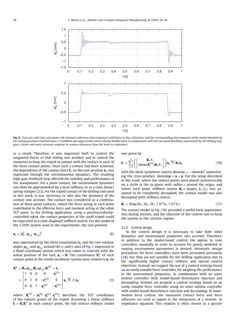
In order to measure the skating during clamp-up, the drill bitwas replaced with a short rod having square cross-section, as seenin Fig. 17. This solution enabled the LVDT to measure skating asclose to the drill tip as possible. The robot was moved close to thesurface before the measurements were initiated. This smallmovement before build-up of the clamp-up pressure caused asmall movement, which was neglected when measuring theactual skating effect. The force feedback control was initiated assoon as the force was detected in the force sensor. The test results
ARTICLE IN PRESS
T. Olsson et al. / Robotics and Computer-Integrated Manufacturing 26 (2010) 24–38 35
showed an LVDT motion of 0.1 mm. It was concluded that mostof the 0.1 mm movement was due to the orientation control of theend-effector. The reason for this was that the LVDT could notmeasure exactly at the TCP point, but rather at a point 3–4 mm upalong the square shaped stick. This phenomenon was increasedwhen drilling on flexible surfaces, where larger orientation controlactions were necessary.
The drilling was performed with a Guhring cutter with a 5 mmbore diameter, and the holes where drilled 15 mm apart. The hole-to-hole cycle time was around 12 s. The actual time to control theclamp-up without skating and with the end-effector orthogonalto the surface took around 2.5 s. Note in the force diagrams inFigs. 13–20 that the thrust force from the drill reduces thepressure between the pressure foot antennas and the work-piece.Keeping the clamp-up pressure higher than the thrust force iscritical to avoid skating effects. In addition to the coupon drillingtests drilling was also made on a very flexible plate. This test wasmade to investigate how well suited this method is to be used in
Fig. 17. Set-up of the LVDT sensors in test configuration.
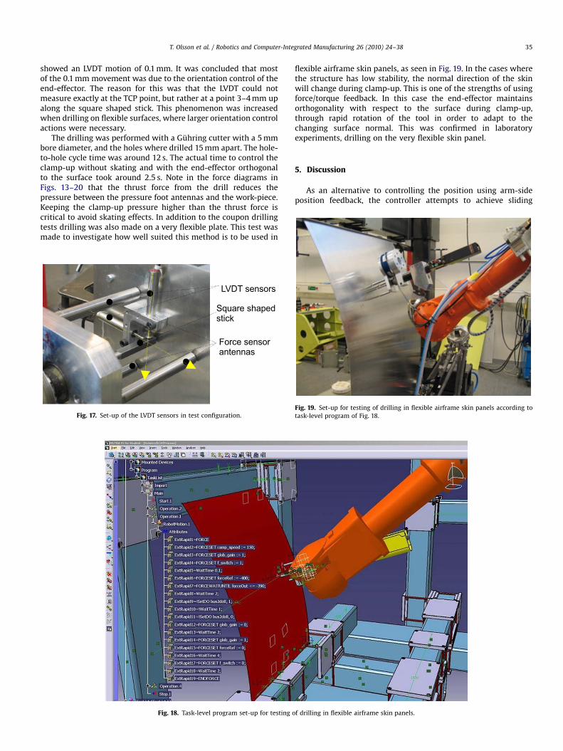
Fig. 18. Task-level program set-up for testing o
flexible airframe skin panels, as seen in Fig. 19. In the cases wherethe structure has low stability, the normal direction of the skinwill change during clamp-up. This is one of the strengths of usingforce/torque feedback. In this case the end-effector maintainsorthogonality with respect to the surface during clamp-up,through rapid rotation of the tool in order to adapt to thechanging surface normal. This was confirmed in laboratoryexperiments, drilling on the very flexible skin panel.
5. Discussion
As an alternative to controlling the position using arm-sideposition feedback, the controller attempts to achieve sliding
f drilling in flexible airframe skin panels.
Fig. 19. Set-up for testing of drilling in flexible airframe skin panels according to
task-level program of Fig. 18.

ARTICLE IN PRESS
0 5 10 15 20 25 30 35 40−400−350−300−250−200−150−100−50
050
0 5 10 15 20 25 30 35 40−10−8−6−4−2
02468
Time [s]
F x, F
y, F z
, [N
]M
x, M
y, M
z [N
m]
Fig. 20. Drilling operation forces Fx , Fy , Fz , Mx , My , Mz vs. time for the end-effector with three antennas also reflecting the drilling operation cycle time, the plate thickness
being 4 mm with holes at a distance of 15 mm.
T. Olsson et al. / Robotics and Computer-Integrated Manufacturing 26 (2010) 24–3836
suppression by making sure that the tangential interaction forcesare always small enough to keep the contact in the stictionregime. In practice, the achievable bandwidth of the force controlis limited by the mechanical bandwidth of the robot, as well as bythe bandwidth of the inner motion control. Therefore, the forcecontrol and sliding suppression must be combined with propermechanical construction in order to obtain a sufficiently stiffsystem. In the proposed solution, the stiffness is effectivelyincreased by the tripod high-friction contact. The contact willdamp and suppress small disturbances, such as vibrations fromthe feeding and rotation of the drilling tool, while the force controland active sliding suppression handles large disturbances at lowerfrequencies, such as the slower variations of the cutting forces.Thereby, a system which is able to reject disturbances over a widefrequency range is obtained, at a potentially very low cost as thesolution requires only a standard force/torque sensor integratedinto the drilling tool. Besides, the accuracy of force and positionmade possible by force control eliminates the need for integrationof expensive, extensive support systems. Whereas there aredifficulties with coupling between different directions in theCartesian space and the linear-model approximation could bechallenged, it should be stressed that in spite of these approxima-tions and error sources it was possible to obtain the performanceneeded for the process.
The drilling force control system differs from most otherapplications of force control, such as polishing, grinding andassembly, where the force control is used to increase thecompliance rather than to improve the stiffness to forcedisturbances. In the drilling system, the model-based inner-loopcompensation improves the stiffness, using one or several localmodels of the robot stiffness and dynamics. In order toexperimentally acquire and tune such models in the approachpresented, extra arm-side position measurements must beavailable during the off-line tuning phase, as methods based onmotor positions only have proved not accurate enough fordetermining the dynamic response to force inputs. As analternative approach, joint-space stiffness models could beconverted to Cartesian space and used instead, although this
approach has not been investigated due to the lack of availablemodels for the experiment robot. In cases when dynamic modelsor arm-side measurements are not available, acceptable resultscan in some configurations be obtained without inner-loopcompensation using proper tuning of the outer force controller.However, the couplings between different degrees of freedommay lead to poor performance, and attempts to increase thebandwidth result in limit cycles and oscillations in the forcecontrol. The model-based approach includes two types ofdecoupling, the first being the dynamic model-based inner-loopdisturbance compensation scheme for the three translationaldegrees of freedom, the second the static decoupling of rotationand translation needed because of the tripod geometry. Thisdivision of the decoupling action into a static and dynamic part isjustified, since the bandwidth requirements on the fast slidingsuppression are much greater than on the comparatively slowcontrol of the contact torques, used to keep the tripod alignedwith the surface. This structure is a great simplification comparedto a full 5-DOF dynamic model and decoupling, and its usefulnessis validated by the experiments.
In addition to the coupon drilling tests, drilling was also madeon a very flexible plate. This test was made to investigate howwell-suited this method is to use with the flexible airframe skinpanels, as depicted in Figs. 18 and 19. In the cases where thestructure has low stability, the skin will not maintain the samenormal direction as it had prior to clamp-up. This is one of thestrengths in using force feedback control measuring all 6-DOFsimultaneously. In this case, the end-effector maintains orthogon-ality with respect to the surface. When the surface normalchanges its direction due to clamp-up, there will be a detection ofnormality error in the force/torque control and the end-effectorwill rotate to adapt to the changing surface normal. This wasconfirmed in the laboratory experiments by drilling on the veryflexible skin panel (Figs. 18 and 19). Drilling operation 6-DOFforces and cycle time are shown in Fig. 20. To our knowledge, useof force control for drilling in flexible sheets has not been reportedelsewhere and, thus, the results cannot be compared with anysuch previous results.

ARTICLE IN PRESS
T. Olsson et al. / Robotics and Computer-Integrated Manufacturing 26 (2010) 24–38 37
In addition to the robotic force control interface [7,17], roboticforce control interfaces and their usage have been reportedelsewhere—e.g., the DLR effort [24], the Comau force controlinterface [28], and the ABB force-controlled machining [8].
6. Conclusions
The use of industrial robots in automatic drilling applicationshas been limited, mainly due to the presence of rapidly varyinginteraction forces in combination with compliance in gear boxesand links. Functionality for high-bandwidth force control inmodern industrial robot control systems could potentially leadto robotic drilling systems with significantly improved perfor-mance, without the use of costly hardware modifications andcalibration procedures. In this paper, we have presented methodsand systems for force-controlled robot drilling. Using a 6-DOFforce/torque sensor, an outer force control loop and a model-basedinner-loop disturbance compensation scheme have been de-signed, and used to control the axial contact force and suppressthe sliding of a tripod contact while the drilling is performed. Theadvantage of the proposed controller is demonstrated in repro-ducible drilling experiments using an industrial robot system.Moreover, the application potential for high-precision roboticdrilling operations in airframe assembly has been demonstrated.
Acknowledgments
This research was made in the framework of the project FlexAAsupported by the Swedish Foundation for Strategic Researchunder the program ProViking. This financial support is gratefullyacknowledged.
The authors are grateful to Magnus Engstrom, Saab Aero-structures, for problem definitions and cooperation within theFlexAA project, and to Anders Blomdell for implementation ofsensor interfaces and real-time software.
Appendix A. XML modifications and ExtRapid programming
Software example of Delmia XML code
In: oxsl:template match ¼ "ActivityList"4
add after first if statement, after line 1048:
oxsl:variable name ¼ "extrapid"
select ¼ "AttributeList/Attribute[AttributeName ¼
’ExtRapid1’]/AttributeValue"/4
Add this if statement at line 1088:
oxsl:if test ¼ " $ postcomment ! ¼ ’’"4
oxsl:call-template name ¼ "processComments"4 oxsl:with-param name ¼ "prefix" select ¼ "’Ext’"/4 oxsl:with-param name ¼ "attributeListNodeSet"select ¼ "AttributeList"/4
o/xsl:call-template4o/xsl:if4
In:oxsl:template match ¼ "Action"4
add this last in the tamplate:
oxsl:call-template name ¼ "processComments"4
oxsl:with-param name ¼ "prefix" select ¼ "’Ext’"/4 oxsl:with-param name ¼ "attributeListNodeSet"select ¼ "AttributeList"/4
o/xsl:call-template4In:oxsl:template match ¼ "Activity"4
add this last in the template (line 1394):
oxsl:call-templatename ¼ "processComments"4
oxsl:with-param name ¼ "prefix" select ¼ "’Ext’"/4 oxsl:with-param name ¼ "attributeListNodeSet"select ¼ "AttributeList"/4
o/xsl:call-template4In:oxsl:template name ¼ "processComments"4
modify the line:
oxsl:if test ¼ "($precomchk ¼ ’PreComment’ and $prefix ¼ ’Pre’)
or ($postcomchk ¼ ’PostComment’ and $prefix ¼ ’Post’)"4
tooxsl:if test ¼ "($ precomchk ¼ ’PreComment’ and $prefix ¼ ’Pre’)
or ($postcomchk ¼ ’PostComment’ and $prefix ¼ ’Post’)
or ($extrapidchk ¼ ’ExtRapid’ and $prefix ¼ ’Ext’)"4
and add in the ’choose’ statement:oxsl:when test ¼ "$extrapidchk ¼ ’ExtRapid’"4
oxsl:text4 o/xsl:text4 oxsl:value-of select ¼ "$attrvalue"/4 oxsl:value-of select ¼ "$cr"/4o/xsl:when4
Appendix B. ExtRapid application
MoveJ pos10, v50, fine, drill_TCP
MoveL pos20, v20, fine, drill_TCP
FORCE
FORCESET ramp_speed : ¼ 150;
FORCESET glob_gain : ¼ 1;
FORCESET f_switch : ¼ 1;
WaitTime 0.1;
FORCESET forceRef : ¼ -400;
FORCEWAITUNTIL forceOuto ¼ �390;
WaitTime 1;SetDO bus2do8, 1;
WaitTime 0.5;
SetDO bus2do8, 0;
FORCESET glob_gain : ¼ 0;
WaitTime 8;
FORCESET glob_gain : ¼ 1;
FORCESET forceRef : ¼ 0;
WaitTime 5;
FORCESET f_switch : ¼ 0;
WaitTime 1;
ENDFORCE
MoveL pos30, v50, fine, drill_TCP
The example force tag above defines a force scope in ExtRapidfor pos20. The force is ramped up with the speed of 150 mm/s;f_switch command starts the impedance controller; force
Ref ¼ �400 is the clamp-up force; forceOut is a trigger value tocontinue with the next ExtRapid program line; SetDo bus2do8,1activates the drilling cycle; glob_gain ¼ 0 stops the forcecontrol loop, which keep the robot steady during drilling.As glob_gain ¼ 1 and forceRef ¼ 0 is executed, the forcecontrol starts again and the clamp-up force is reduced to zerobefore moving the end-effector to pos30 in the Rapid program;pos30 is a position some distance away from the airframe.
References
[1] Summers M. Robot capability test and development of industrial robotpositioning system for the aerospace industry. In: SAE 2005 AeroTechCongress & Exhibition, Grapevine, TX, SAE Technical Papers 2005-01-3336,October 2005.
[2] Atkinson J, Hartmann JL, Jones S, Gleeson P. Robotic drilling system for 737aileron. In: SAE 2007 AeroTech Congress & Exhibition, Los Angeles, CA, USA,SAE Technical Papers 2007-01-3821, September 2007.
[3] Degoulange E, Dauchez P, Pierrot F, Prat P. Determination of a reference modelfor controlling the deformation of an industrial robot. Application to rivetingin aeronautics. In: Proceedings of the IEEE/RSJ international conference onintelligent robots and systems, vol. 1, 1994. p. 343–51.

ARTICLE IN PRESS
T. Olsson et al. / Robotics and Computer-Integrated Manufacturing 26 (2010) 24–3838
[4] Kihlman H. Affordable automation for airframe assembly—development ofkey enabling technologies. PhD thesis, Linkoping University, Linkoping,Sweden, PhD thesis 953; 2005.
[5] Van Duin S. A comparison of indoor GPS versus laser tracking metrology forrobotic drilling. In: Aerospace manufacturing and automated fasteningconference and exhibition, Toulouse, France, 2006.
[6] Van Duin S, Kihlman H. Robotic normalizing force feedback. In: SAE 2005AeroTech Congress & Exhibition, Grapevine, TX, 2005.
[7] Blomdell A, Bolmsjo G, Brogardh T, Cederberg P, Isaksson M, Johansson R, etal. Extending an industrial robot controller—implementation and applica-tions of a fast open sensor interface. IEEE Robotics and Automation Magazine2005;12(3):85–94.
[8] Zhang H, Gan Z, Wang J, Zhang G. Machining with flexible manipulator:towards improving robotic machining performance. In: Proceedings of the2005 IEEE/ASME international conference on advanced intelligent mecha-tronics, July 2005. p. 1127–32.
[9] Siciliano B, Villani L. Robot force control. Dordrecht, NL: Kluwer AcademicPublishers; 1999.
[10] Caccavale F, Natale C, Siciliano B, Villani L. Integration for the next generation:embedding force control into industrial robots. IEEE Robotics and AutomationMagazine 2005;12(3):53–64.
[11] Johansson R, Spong M. Quadratic optimization of impedance control. In:Proceedings of the 1994 IEEE international conference on robotics andautomation, San Diego, CA, May 8–13, 1994. p. 616–21.
[12] Kawaji S, Arao M, Chen Y. Thrust force control of drilling system using neuralnetwork. In: Proceedings of the IEEE/ASME international conference onadvanced intelligent mechatronics, vol. 1, Como, Italy, 2001. p. 476–81.
[13] Alici G. A systematic approach to develop a force control system for roboticdrilling. Industrial Robot: An International Journal 1999;26(5):389–97.
[14] Lee W, Shih C. Control and breakthrough detection of a three-axis roboticbone drilling system. Mechatronics 2006;16(2):73–84.
[15] ABB Robotics. Application manual—force control for assembly. Technicalmanual, Ref. 3HAC025057-001, 2005.
[16] Nilsson K, Johansson R. Integrated architecture for industrial robot program-ming and control. Journal of Robotics and Autonomous Systems 1999;29:205–26.
[17] Johansson R, Robertsson A, Nilsson K, Brogardh T, Cederberg P, Olsson M, et al.Sensor integration in task-level programming and industrial robotic taskexecution control. Industrial Robot: An International Journal 2004;31(3):284–96.
[18] Ekman T, Hedin G. The JastAdd system—modular extensible compilerconstruction. Science of Computer Programming 2007;69(1–3):14–26.
[19] Haage M. Flexible interactions with productive robots in partly unstructuredenvironments. Licentiate thesis LU-CS-LIC:2004-2, Department of ComputerScience, Lund University, Lund, Sweden, ISSN 1652-4691; June 2004.
[20] Olsson T, Robertsson A, Johansson R. Flexible force control for accurate low-cost robot drilling. In: IEEE international conference on robotics andautomation (ICRA 2007), Rome, Italy, 2007. p. 4770–5.
[21] Shiriaev A, Robertsson A, Johansson R. Friction compensation for passivesystems based on the LuGre model. In: Proceedings of the 2nd IFAC workshopon Lagrangian and Hamiltonian methods for nonlinear control, Seville, Spain,2003. p. 183–8.
[22] Canudas de Wit C, Olsson H, Astrom K, Lischinsky P. A new model for controlof systems with friction. IEEE Transactions on Automatic Control1995;40(3):419–25.
[23] Diolaiti N, Melchiorri C, Stramigioli S. Contact impedance estimation forrobotic systems. IEEE Transactions on Robotics 2005;21(5):925–36.
[24] Natale C, Koeppe R, Hirzinger G. A systematic design procedure of forcecontrollers for industrial robots. IEEE/ASME Transactions on Mechatronics2000;5(2):122–31.
[25] Olsson T. High-speed vision and force feedback for motion-controlledindustrial manipulators. PhD thesis, Department of Automatic Control, LundUniversity, TFRT-1078; May 2007.
[26] Olsson T, Johansson R, Robertsson A. Force/vision based active dampingcontrol of contact transition in dynamic environments. In: Dynamical vision.Lecture notes in computer science, vol. 4358. Berlin, Heidelberg, New York:Springer; 2007. p. 299–313, ISBN 978-3-540-70931-2.
[27] Kihlman H, Brogardh T, Haage M, Nilsson K, Olsson T. On the use of forcefeedback for cost efficient robotic drilling. In: SAE 2007 AeroTech Congress &Exhibition, Los Angeles, CA; 2007 SAE Paper 2007-01-3909.
[28] Lippiello V, Siciliano B, Villani L. An open architecture for sensory feedbackcontrol of a dual-arm industrial robotic cell. Industrial Robot: An Interna-tional Journal 2007;34(1):46–53.