Cost analysis of network sharing in FTTH/PONs
9
IEEE Communications Magazine • August 2014 126 0163-6804/14/$25.00 © 2014 IEEE Juan Rendon Schneir and Yupeng Xiong are with Huawei Technologies. The views expressed in this article are those of the authors and do not neces- sarily reflect the opinion of the authors’ employer. INTRODUCTION The improvement of broadband access capacity is on the agenda of many operators as well as regional and national administrations worldwide. Potential investors are undertaking techno-eco- nomic evaluations to determine advantages and disadvantages of the different networks available in the market. Fiber to the home (FTTH) is a future-proof fixed-access network that provides a much higher transmission capacity than cable- or copper-based networks. However, a challenge associated with FTTH deployment is the high cost of the passive infrastructure, particularly of the civil works, which correspond to the majority of the whole investment. This fact, together with the uncertain number of subscribers that can be reached in competitive markets or in markets where users have limitations in terms of broad- band affordability, increases the investment risk [1]. One way in which operators could possibly reduce the amount of investment required to deploy fiber-access networks is to share the net- work infrastructure, thereby reducing the invest- ment needed to deploy and operate the FTTH network. Several operators have already deployed or selected FTTH/passive optical networks (PONs) as the access network. Operators that already own or are planning to invest in PONs have been examining the broadband transmission capacity that can be achieved over the next few years with current and future versions of PONs. The improvement of the transmission capacity and other features of PONs has been included in the standardization process. The pre-standards forum Full Service Access Network (FSAN) has been actively involved in the definition of next- generation (NG) PONs, which are referred to as NG-PON1 and NG-PON2. Among other topics, the standardization groups have discussed the type of wavelength-division multiplexing (WDM) that should be used. WDM improves transmis- sion capacity by utilizing different wavelengths on the same fiber [2]. New standardized versions of PON architectures will likely be deployed over the coming years. Given that a network sharing (NS) approach might offer a way of overcoming the financial limitations of operators interested in deploying FTTH/PONs, the cost implications of sharing these networks dictate investigation. A few stud- ies have addressed the cost implications of vari- ous features of PONs [3–5]. Some have compared the cost of deploying different fiber- based access networks [6, 7]. Others have exam- ined the regulatory implications of co-investing in next-generation access (NGA) networks [8, 9]. The economic effects of co-investing in PONs for a few scenarios have been addressed in [10]. However, there are still several aspects of network sharing that have not been addressed in the above mentioned studies. The purpose of this article is to contribute to the clarification of the cost implications of sharing different types of FTTH/PONs. The following research question is addressed: What are the economic implications of a network-sharing scheme for operators that decide to make a joint investment in FTTH/PONs? We tackle this question by utilizing a cost model to derive the deployment cost of FTTH/PON architectures shared by several operators. Standardized networks and networks that are in the standardization process have been used in the study: gigabit PON (GPON), 10- gigabit-capable PON (XG-PON), time- and wavelength-division multiplexing and WDM PON (TWDM-PON), and arrayed waveguide grating (AWG)-based WDM-PON. Urban, sub- urban, and rural geotypes based on average val- ues of select European countries are employed. The rest of the article is organized as follows. In the next section, we describe the FTTH/PONs used for the analysis and the technical ways in which distinct operators can share them. We then describe the network scenarios and the costing methodology employed. We present the results of the cost assessment, which are based on the analysis of the following four metrics: the ABSTRACT This article examines the cost implications of a network-sharing scheme for different fiber to the home/passive optical network architectures. Varied metrics are employed to understand the effect of a network-sharing arrangement on costs. The results show that for the majority of cases studied, the cost per home connected and the payback period increase when employing a network-sharing scheme, but the initial invest- ment is strongly reduced. The reuse of existing passive infrastructure does not bring any cost advantage in comparison to the standalone sce- nario, but it helps to reduce the total cost per home connected. OPTICAL COMMUNICATIONS Juan Rendon Schneir and Yupeng Xiong Cost Analysis of Network Sharing in FTTH/PONs
Transcript of Cost analysis of network sharing in FTTH/PONs

IEEE Communications Magazine • August 2014126 0163-6804/14/$25.00 © 2014 IEEE
Juan Rendon Schneir andYupeng Xiong are withHuawei Technologies.
The views expressed inthis article are those of theauthors and do not neces-sarily reflect the opinionof the authors’ employer.
INTRODUCTION
The improvement of broadband access capacityis on the agenda of many operators as well asregional and national administrations worldwide.Potential investors are undertaking techno-eco-nomic evaluations to determine advantages anddisadvantages of the different networks availablein the market. Fiber to the home (FTTH) is afuture-proof fixed-access network that provides amuch higher transmission capacity than cable- orcopper-based networks. However, a challengeassociated with FTTH deployment is the highcost of the passive infrastructure, particularly ofthe civil works, which correspond to the majorityof the whole investment. This fact, together withthe uncertain number of subscribers that can bereached in competitive markets or in marketswhere users have limitations in terms of broad-band affordability, increases the investment risk[1]. One way in which operators could possiblyreduce the amount of investment required todeploy fiber-access networks is to share the net-work infrastructure, thereby reducing the invest-ment needed to deploy and operate the FTTHnetwork.
Several operators have already deployed orselected FTTH/passive optical networks (PONs)as the access network. Operators that alreadyown or are planning to invest in PONs havebeen examining the broadband transmissioncapacity that can be achieved over the next fewyears with current and future versions of PONs.The improvement of the transmission capacityand other features of PONs has been included inthe standardization process. The pre-standards
forum Full Service Access Network (FSAN) hasbeen actively involved in the definition of next-generation (NG) PONs, which are referred to asNG-PON1 and NG-PON2. Among other topics,the standardization groups have discussed thetype of wavelength-division multiplexing (WDM)that should be used. WDM improves transmis-sion capacity by utilizing different wavelengthson the same fiber [2]. New standardized versionsof PON architectures will likely be deployedover the coming years.
Given that a network sharing (NS) approachmight offer a way of overcoming the financiallimitations of operators interested in deployingFTTH/PONs, the cost implications of sharingthese networks dictate investigation. A few stud-ies have addressed the cost implications of vari-ous features of PONs [3–5]. Some havecompared the cost of deploying different fiber-based access networks [6, 7]. Others have exam-ined the regulatory implications of co-investingin next-generation access (NGA) networks [8, 9].The economic effects of co-investing in PONsfor a few scenarios have been addressed in [10].
However, there are still several aspects ofnetwork sharing that have not been addressed inthe above mentioned studies. The purpose ofthis article is to contribute to the clarification ofthe cost implications of sharing different types ofFTTH/PONs. The following research question isaddressed: What are the economic implications ofa network-sharing scheme for operators that decideto make a joint investment in FTTH/PONs?
We tackle this question by utilizing a costmodel to derive the deployment cost ofFTTH/PON architectures shared by severaloperators. Standardized networks and networksthat are in the standardization process have beenused in the study: gigabit PON (GPON), 10-gigabit-capable PON (XG-PON), time- andwavelength-division multiplexing and WDMPON (TWDM-PON), and arrayed waveguidegrating (AWG)-based WDM-PON. Urban, sub-urban, and rural geotypes based on average val-ues of select European countries are employed.
The rest of the article is organized as follows.In the next section, we describe the FTTH/PONsused for the analysis and the technical ways inwhich distinct operators can share them. Wethen describe the network scenarios and thecosting methodology employed. We present theresults of the cost assessment, which are basedon the analysis of the following four metrics: the
ABSTRACT
This article examines the cost implications ofa network-sharing scheme for different fiber tothe home/passive optical network architectures.Varied metrics are employed to understand theeffect of a network-sharing arrangement oncosts. The results show that for the majority ofcases studied, the cost per home connected andthe payback period increase when employing anetwork-sharing scheme, but the initial invest-ment is strongly reduced. The reuse of existingpassive infrastructure does not bring any costadvantage in comparison to the standalone sce-nario, but it helps to reduce the total cost perhome connected.
OPTICAL COMMUNICATIONS
Juan Rendon Schneir and Yupeng Xiong
Cost Analysis of Network Sharing inFTTH/PONs
SCHNEIR_LAYOUT.qxp_Layout 7/30/14 1:59 PM Page 126

IEEE Communications Magazine • August 2014 127
required initial investment, the cost per homeconnected, the payback period, and the effect ofthe existing passive infrastructure on the totalcost. Finally, our conclusions are provided.
PON ARCHITECTURESThe four PON architectures described in thisarticle are currently under consideration fordeployment by different operators in Europeand other regions around the world. The XG-PON and TWDM-PON have been studied ini-tially in the FSAN. The FSAN specifications aresubmitted to the International Telecommunica-tion Union — Telecommunication StandardsSector (ITU-T) in order to proceed with stan-dardization. The standards related to GPON andXG-PON have been developed by the subgroupreferred to as Question 2 (Q2) of ITU-T StudyGroup 15 (SG15), which deals with optical accessnetworks. This subgroup has also been address-ing the standardization task related to TWDM-PONs. Subgroup Question 6 (Q6) of ITU-TSG15 is working on the standards related tometro WDM technologies. The AWG-basedWDM-PON architecture described in this articleis based on Recommendation G.698.3, whichwas approved by subgroup Q6 [11]. This networkwas approved as a metro network, and a fewoperators are evaluating the possibility of usingit in the access network.
GPON is commercially available and hasbeen deployed by several operators in differentcountries. The downlink and uplink capacitiesare 2.5 and 1.2 Gb/s, respectively. The splittingfactor can, in theory, be up to 128. However, inpractice, operators employ a value of 64 orlower. Different operators cannot physicallyshare a fiber because all the signals work withthe same wavelength pairs. Operators needmulti-fiber deployment in order to physicallyshare the GPON architecture.
The XG-PON was defined as part of the NG-PON1 standardization path. ITU-T Recommen-dation G.987 describes the features of XG-PONs[12]. The downlink capacity is 10 Gb/s, whereasthe uplink capacity is 2.5 Gb/s. In practice, it isexpected that operators will employ a splittingfactor of up to 128. Different signals use thesame wavelength pairs. Therefore, physical shar-ing of the same fiber is not possible, and opera-tors need to utilize multi-fiber deployment toshare XG-PON. With XG-PON, the same pas-sive infrastructure used for GPONs (i.e., splittersand fiber cables) can be employed in the XG-PON architecture.
The TWDM-PON is the primary solution inthe NG-PON2 standardization path. WithTWDM, it will be possible to stack at least four10 Gb/s signals instead of one 40 Gb/s signal,and potentially as many as eight or more. Thedownlink capacity of a port is 40 Gb/s (4 × 10Gb/s), and the uplink capacity is 10 Gb/s (4 ×2.5 Gb/s). The splitting factor will be at least 256[13]. Physical unbundling of a fiber is possiblebecause operators can employ different wave-lengths. A WDM multiplexer (mux), which isused to combine signals from different opera-tors, can support up to four or eight XG-PONlines (ports). The same passive infrastructure
(i.e., fiber cables and splitters) employed forGPONs and XG-PONs can be reused forTWDM-PON deployment.
In AWG-based WDM-PON architectures thedownlink and uplink transmission capacity persubscriber is 1.25 Gb/s, and a fiber has a totaltransmission capacity of 40 Gb/s (32 × 1.25Gb/s). It has yet to be defined whether there willbe 16, 32, or 48 wavelengths per fiber. Oneadvantage of the AWG-based WDM-PON is theminimum capacity that can be assigned to oneuser. TWDM-PONs can have the same transmis-sion capacity as AWG-based WDM-PONs. How-ever, if the TWDM-PON architecture employs ahigher splitting factor (e.g., 64 or 128), the guar-anteed transmission capacity per user will belower.
IMPLEMENTATION OF THECOST MODEL
NETWORK ARCHITECTURESIn the approach adopted in this study, it isassumed that the operators that make the ini-tial co-investment create a special-purposeentity (SPE), which will deploy and maintainthe passive infrastructure, and be in charge ofproviding the owners of the SPE with a darkfiber service. Each operator is in charge ofdeploying and maintaining its own active infra-structure. Each operator can provide voice,video, or data services, or sell wholesale accessto the active and passive infrastructure to aservice provider. In other words, each opera-tor has the possibility of reselling a high-speedaccess link to a third party in bitstream mode.Figure 1 shows the principal components ofthe passive infrastructure used in the fourPON architectures: the in-house cabling, split-ters, and optical distribution frames (ODFs)located in the building for the case of a fewPONs; and the distribution segment, streetcabinet, feeder segment, and ODF in the cen-tral office. The active elements, which are alsodepicted in Fig. 1, include the optical networkterminal (ONT) in the user’s home and theoptical line terminal (OLT), with the PON andupstream Ethernet ports in the central office.The network architectures depicted in Fig. 1are similar to the networks described in [10].The SPE should ensure that there are no inter-operability problems between the active equip-ment employed by the different operators. Forexample, the operators will have to buy ONTsthat are pre-approved by the SPE and alsoenable various service providers to offer dif-ferent services.
In our example, there are two splitting levelsin the GPON, XG-PON, and TWDM-PONarchitectures: 1:8 in the street cabinet and 1:4 inthe basement of the building, which gives a totalsplitting factor of 1:32 per PON port. The WDMmux used in the TWDM-PON architecture islocated in the central office; it combines the sig-nals that arrive from the OLTs of the operatorsand transmits these through a single fiber. Byusing a splitting factor of 32, the average down-link transmission capacity per user in the GPON,XG-PON, and TWDM-PON architectures is 78
In the approach
adopted in this
study, it is assumed
that the operators
that make the initial
co-investment create
a special-purpose
entity (SPE), which
will deploy and
maintain the passive
infrastructure, and
be in charge of pro-
viding the owners of
the SPE with a dark
fiber service.
SCHNEIR_LAYOUT.qxp_Layout 7/30/14 1:59 PM Page 127

IEEE Communications Magazine • August 2014128
Figure 1. FTTH/PON architectures: a) GPON; b) XG-PON; c) TWDM-PON; d) AWG-based WDM-PON.
Central office
Splitter 1:4
Fiber
Fiber
OLT
OLT ODF
a)
Distributionsegment
Fiber
Feedersegment
GPONport
Ethernetport
GPONport
Ethernetport
Streetcabinet
Splitter 1:8ODF
ONT
ONT
Operator 2
Operator 1
Shared infrastructureOperator 1’s infrastructureOperator 2’s infrastructure
Central office
Splitter 1:4
Fiber
Fiber
OLT
OLT ODF
b)
Distributionsegment
Fiber
Feedersegment
GPONport
Ethernetport
GPONport
Ethernetport
Streetcabinet
Splitter 1:8ODF
ONT
ONT
Operator 2
Operator 1
Central office
Splitter 1:4
Fiber
Fiber
OLT
OLT ODF
c)
Distributionsegment
Fiber
Feedersegment
GPONport
Ethernetport
WDMMUX
Ethernetport
Streetcabinet
Splitter 1:8
ONT
ONT
Operator 2
Operator 1
TWDM-PONport
TWDM-PONport
Central office
Fiber
Fiber
OLT
OLTODF
d)
Distributionsegment
Fiber
FeedersegmentEthernet
port
AWG(1:32)Ethernet
port
Streetcabinet
AWG (1:32)
ONT
ONT
Operator 2
Operator 1
WDM-PONport
WDM-PONport
SCHNEIR_LAYOUT.qxp_Layout 7/30/14 1:59 PM Page 128

IEEE Communications Magazine • August 2014 129
Mb/s, 312 Mb/s, and 1.25 Gb/s, respectively.These average values were derived by dividingthe capacity of one PON port by the splittingfactor. In fact, the real transmission capacity ofeach PON user will depend on the broadbandconsumption of all the users in the access seg-ment that are transmitting and receiving simulta-neously. The downlink capacity of one user ofthe AWG-based WDM-PON is 1.25 Gb/s. Forcomparison purposes, the AWG in the AWG-based WDM-PON architecture supports up to32 users. As depicted in Fig. 1, in this study, theAWG-based WDM-PON architecture includesan AWG located in the street cabinet. There-fore, there must be at least one fiber per enduser in the distribution segment. There is nosharing of fiber in the distribution segment. Itcan be seen that there is a point-to-point (P2P)link between the ONT and the AWG located inthe street cabinet.
Three scenarios were considered in the study.In the first scenario, only one operator invests inthe fiber access network, and the passive infra-structure is deployed in single-fiber mode. Thesecond and third co-investment scenarios use anetwork-sharing scheme, which consists of thedeployment of enough passive infrastructure forup to four operators in the feeder and distribu-tion segments. In the second and third scenarios,two and three operators share the network,respectively.
Three geotypes were modeled: urban, sub-urban, and rural. Usually, these geotypes areemployed in cost studies of FTTH deploymentsto simplify the different scenarios that are pos-sible within a country [14, 15]. The geotypesare based on average values of three Europeancountries: France, Germany, and the UnitedKingdom. The main differences between thesegeotypes are the size of the distribution andthe feeder segments, and the number of centraloffices, street cabinets, and subscribers. In theurban geotype, the density of users is high, andthe size of the feeder and the distribution seg-ments is relatively short. In the rural geotype,the subscriber density is low, and the size ofthe feeder and the distribution segments islarge. The suburban geotype has intermediatevalues. The values of the segment lengths andthe prices of the passive network componentsand network deployment were collectedthrough interviews with multiple companiesthat deploy passive infrastructure in the above-mentioned countries. The length of the feedersegment in the urban, suburban, and ruralareas is 850 m, 1200 m, and 2500 m, respec-tively, whereas the length of the distributionsegment in the same areas is 80 m, 145 m, and220 m, respectively. The cost of digging andpreparing the trench for urban, suburban andrural areas is US$120/m, US$100/m, andUS$88/m, respectively. The cost of the networkelements that are still not commercially avail-able at the time of writing this article, such asthe ONTs and the PON line cards of theTWDM-PON architecture, were derived byusing current market costs of the componentsof the products and considering, based ontrends of previous years, that the cost willdecrease with a sales volume increase.
COST MODEL
The cost model is essentially based on a green-field deployment; that is, all the network compo-nents that appear in Fig. 1 should be installed.However, at the end of the article we also ana-lyze cases in which ducts in the feeder and distri-bution segments are already available,corresponding to a brownfield deployment.
The cost of a home connected includes all theaccess network elements, from the Ethernetupstream port in the OLT to the ONT in theuser premises. The value derived for the cost of ahome passed does not include the cost of the in-house cable or the ONT. The total cost of owner-ship (TCO) includes capital expenditures(CAPEX) and operational expenditures (OPEX).The calculations of the cost per home connectedand per home passed consider a timeframe of 15years. The OPEX values of the network elementswere derived by employing mark-up values: 4percent for the active infrastructure and 1 per-cent for the passive infrastructure. The OPEXvalues include, among other items, the cost torepair or replace the network components whenthey stop working. In the central office, theOPEX also includes the costs of the energy con-sumption of the active elements and the floorspace rental. The lifetime of the passive infra-structure is 30 years. The lifetime of active equip-ment is at most 10 years. In particular, it wasassumed that the lifetimes of the OLT and ONTare 10 and 6 years, respectively.
Figure 1 shows the network elements in thecentral office and in-house segment that areshared. The entire infrastructure in the feederand distribution segments and street cabinet isshared when using the network sharing scheme.The cost of the feeder and distribution segmentsincludes the cost of digging and preparing thetrench, manholes, and deploying the fiber. Thestreet cabinet includes the cabinet, the splittersor AWG, and the cost of splicing the fibers.
The values of the cost per home passed andcost per home connected were derived by usingthe cumulative present value (CPV) formulawith a discount rate of 9 percent. In this study,only the cost of the fiber-based access networkwas taken into account. The cost of the core andmetro aggregation networks, the marketing andsales costs, the cost of the systems required tomanage and provision shared access, administra-tive costs of the SPE that manages the passiveinfrastructure, the cost of the necessary permitsto deploy the infrastructure, the cost of engi-neering drawings, as well as the cost of providingservices such as telephony, video, or broadbandwere not included in the cost model.
In the cost model, the network was deployedin equal proportions over the first four years.For the calculation of the cost per home con-nected, it is necessary to know the number ofsubscribers each operator owns. Therefore, atarget market share was employed. It wasassumed that an operator reached 22.5, 45.0,67.5, and 90.0 percent of the target market shareover the first, second, third, and fourth years,respectively. Afterward, the take-up rate is 0.96percent, which enables the operator to reach 100percent of the target market share in 15 years.
In the cost model,
the network was
deployed in equal
proportions over the
first four years. For
the calculation of the
cost per home con-
nected, it is neces-
sary to know the
number of sub-
scribers each
operator owns.
Therefore, a target
market share was
employed.
SCHNEIR_LAYOUT.qxp_Layout 7/30/14 1:59 PM Page 129

IEEE Communications Magazine • August 2014130
COST ASSESSMENT
INITIAL INVESTMENTTo calculate the initial investment needed to rollout a network in a region, operators usually cal-culate the cost per home passed. This cost corre-sponds to the required CAPEX and depends onall of the potential subscribers or householdsthat can be connected (i.e., 100 percent marketshare). Table 1 shows the cost per home passedfor the three deployment scenarios. There arestrong differences between the costs per homepassed for the urban, suburban, and rural geo-types.
According to the numbers in Table 1, the costfor operators on shared networks is lower thanthe cost of one operator deploying the networkalone, and this is true regardless of which net-work architecture or geotype is analyzed. In thescenario where two operators share the network,the cost of each operator in comparison to thecost of an operator that deploys the networkalone ranges from 50 percent for the AWG-based WDM-PON architecture to 60 percent forthe GPON architecture. When three operatorsshare the network, the cost of each operator incomparison with the cost of one operator thatdeploys the network alone ranges from 33 to 45percent.
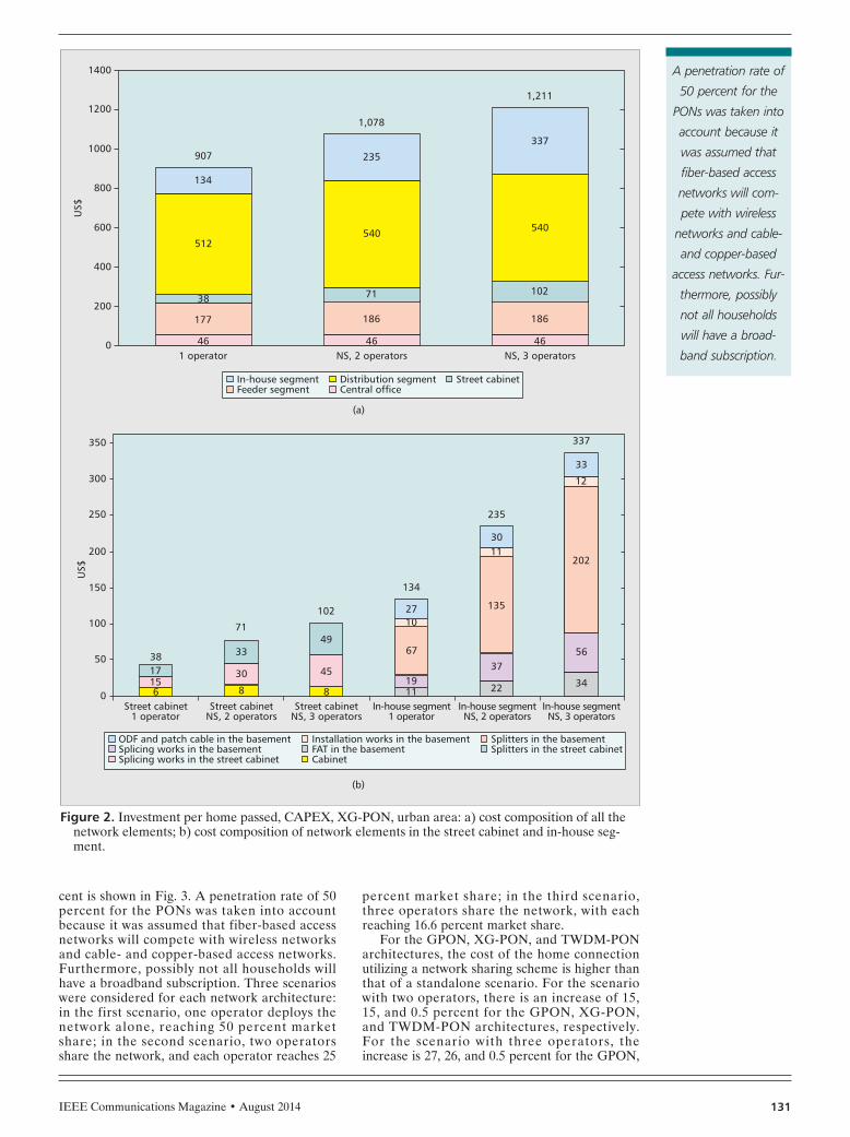
In comparison with the standalone scenario,operators engaged in the co-investment modelthat employs GPON, XG-PON, or TWDM-PONmust add additional infrastructure in order toshare the network. For the TWDM-PON archi-tecture, it is necessary to employ the WDM muxin the central office, which results in slightincreases of the total cost: up to 0.6 and 0.7 per-cent more for the scenarios with two and threeoperators, respectively. For the cases includingGPON and XG-PON architectures, differentnetwork elements must be added to share thenetwork. Figure 2a shows the composition of thetotal cost required by all the operators to deploythe XG-PON in an urban area. By dividing thetotal costs that appear in Figure 2a (US$907,US$1078, and US$1211) by the number of oper-ators that use the network, it is possible to obtainthe values shown in Table 1: US$907, US$539,and US$404 for one, two, and three operators,respectively.
In Figure 2a, the costs per home passed forthe central office are identical: US$46. In thecost model, it was assumed that for the three
scenarios there is 10 percent spare capacity forthe components located in the central office.The cost of the feeder segment for the two net-work-sharing scenarios, US$186, is higher thanthe cost for the standalone scenario, US$177. Anidentical situation appears in the distributionsegment where US$540 and US$512 are requiredfor the network sharing and standalone scenar-ios, respectively. For the XG-PON architecture,a multi-fiber deployment is necessary for net-work sharing, which requires the deployment ofenough infrastructure to support additionalfibers in the feeder and distribution segments.This leads to an increase of the cost of thesesegments.
Figure 2b shows the cost components of thestreet cabinet (US$38, US$71, and US$102) andin-house segments (US$134, US$235, andUS$337). These values correspond to the exam-ples shown in Fig. 2a. More splitters and addi-tional splicing efforts are required in the streetcabinet. Moreover, a larger street cabinet isneeded for the network sharing scenarios inorder to support more splitters. In the in-housesegment, the splitters will be located in a fiberaccess terminal (FAT), and every operator willhave allocated a FAT with the correspondingsplitters. The total costs of the following networkcomponents located in the basement willincrease when using the network-sharing scheme:FAT, splitters, ODF, patch cable, splicing works,and the corresponding installation works.
As depicted in Fig. 2a for the case with oneoperator, the cost percentage of the feeder anddistribution segments, which are the sections ofthe access network that require more invest-ment, adds up to 19 and 56 percent, respectively.Even though additional infrastructure is neededin almost all sections of the XG-PON to enablea network sharing scheme — particularly in thestreet cabinet and in-house segment — sharingthe access network strongly reduces the totalcost per home passed per operator.
COST PER HOME CONNECTEDThe cost per home connected is a value thatincludes CAPEX and OPEX and depends onthe market share; it reflects the amount of capi-tal necessary to connect one subscriber to thenetwork over a certain period. A comparison ofthe cost per home connected for the four PONarchitectures in an urban area when the totalmarket share of all operators adds up to 50 per-
Table 1. Investment per home passed per operator (US$), CAPEX.
Urban Suburban Rural
GPON XG-PON
TWDM-PON
AWG-basedWDM-PON
GPON XG-PON
TWDM-PON
AWG-basedWDM-PON
GPON XG-PON
TWDM-PON
AWG-basedWDM-PON
1 op 892 907 949 1332 1558 1573 1613 2020 2602 2615 2657 3096
NS, 2ops 532 539 480 666 881 888 812 1010 1440 1446 1334 1548
NS, 3ops 399 404 320 444 630 634 541 673 1008 1013 889 1032
SCHNEIR_LAYOUT.qxp_Layout 7/30/14 2:00 PM Page 130
IEEE Communications Magazine • August 2014 131
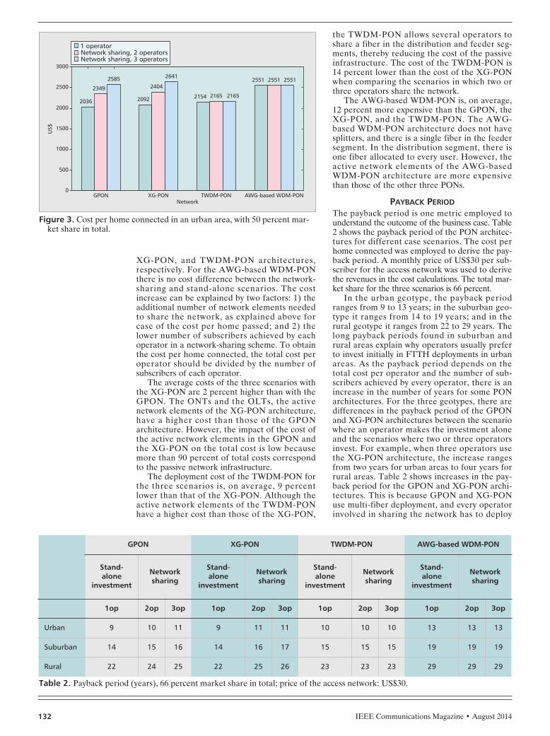
cent is shown in Fig. 3. A penetration rate of 50percent for the PONs was taken into accountbecause it was assumed that fiber-based accessnetworks will compete with wireless networksand cable- and copper-based access networks.Furthermore, possibly not all households willhave a broadband subscription. Three scenarioswere considered for each network architecture:in the first scenario, one operator deploys thenetwork alone, reaching 50 percent marketshare; in the second scenario, two operatorsshare the network, and each operator reaches 25
percent market share; in the third scenario,three operators share the network, with eachreaching 16.6 percent market share.
For the GPON, XG-PON, and TWDM-PONarchitectures, the cost of the home connectionutilizing a network sharing scheme is higher thanthat of a standalone scenario. For the scenariowith two operators, there is an increase of 15,15, and 0.5 percent for the GPON, XG-PON,and TWDM-PON architectures, respectively.For the scenario with three operators, theincrease is 27, 26, and 0.5 percent for the GPON,
Figure 2. Investment per home passed, CAPEX, XG-PON, urban area: a) cost composition of all thenetwork elements; b) cost composition of network elements in the street cabinet and in-house seg-ment.
1 operator
200
US$
0
400
600
800
1000
1200
1400
(a)
(b)
In-house segmentFeeder segment
Distribution segmentCentral office
Street cabinet
ODF and patch cable in the basementSplicing works in the basementSplicing works in the street cabinet
Installation works in the basementFAT in the basementCabinet
Splitters in the basementSplitters in the street cabinet
46
177
38
512
134
907
46
186
71
540
235
1,078
46
186
102
540
337
1,211
NS, 2 operators NS, 3 operators
Street cabinet1 operator
50
US$
0
100
150
200
250
300
350
6151738
8
30
33
71
8
45
49
102
11
1027
19
67
134
22
1130
37
135
235
34
12
33
56
202
337
Street cabinetNS, 2 operators
Street cabinetNS, 3 operators
In-house segment1 operator
In-house segmentNS, 2 operators
In-house segmentNS, 3 operators
A penetration rate of
50 percent for the
PONs was taken into
account because it
was assumed that
fiber-based access
networks will com-
pete with wireless
networks and cable-
and copper-based
access networks. Fur-
thermore, possibly
not all households
will have a broad-
band subscription.
SCHNEIR_LAYOUT_Layout 7/30/14 4:59 PM Page 131
IEEE Communications Magazine • August 2014132
XG-PON, and TWDM-PON architectures,respectively. For the AWG-based WDM-PONthere is no cost difference between the network-sharing and stand-alone scenarios. The costincrease can be explained by two factors: 1) theadditional number of network elements neededto share the network, as explained above forcase of the cost per home passed; and 2) thelower number of subscribers achieved by eachoperator in a network-sharing scheme. To obtainthe cost per home connected, the total cost peroperator should be divided by the number ofsubscribers of each operator.
The average costs of the three scenarios withthe XG-PON are 2 percent higher than with theGPON. The ONTs and the OLTs, the activenetwork elements of the XG-PON architecture,have a higher cost than those of the GPONarchitecture. However, the impact of the cost ofthe active network elements in the GPON andthe XG-PON on the total cost is low becausemore than 90 percent of total costs correspondto the passive network infrastructure.
The deployment cost of the TWDM-PON forthe three scenarios is, on average, 9 percentlower than that of the XG-PON. Although theactive network elements of the TWDM-PONhave a higher cost than those of the XG-PON,
the TWDM-PON allows several operators toshare a fiber in the distribution and feeder seg-ments, thereby reducing the cost of the passiveinfrastructure. The cost of the TWDM-PON is14 percent lower than the cost of the XG-PONwhen comparing the scenarios in which two orthree operators share the network.
The AWG-based WDM-PON is, on average,12 percent more expensive than the GPON, theXG-PON, and the TWDM-PON. The AWG-based WDM-PON architecture does not havesplitters, and there is a single fiber in the feedersegment. In the distribution segment, there isone fiber allocated to every user. However, theactive network elements of the AWG-basedWDM-PON architecture are more expensivethan those of the other three PONs.
PAYBACK PERIODThe payback period is one metric employed tounderstand the outcome of the business case. Table2 shows the payback period of the PON architec-tures for different case scenarios. The cost perhome connected was employed to derive the pay-back period. A monthly price of US$30 per sub-scriber for the access network was used to derivethe revenues in the cost calculations. The total mar-ket share for the three scenarios is 66 percent.
In the urban geotype, the payback periodranges from 9 to 13 years; in the suburban geo-type it ranges from 14 to 19 years; and in therural geotype it ranges from 22 to 29 years. Thelong payback periods found in suburban andrural areas explain why operators usually preferto invest initially in FTTH deployments in urbanareas. As the payback period depends on thetotal cost per operator and the number of sub-scribers achieved by every operator, there is anincrease in the number of years for some PONarchitectures. For the three geotypes, there aredifferences in the payback period of the GPONand XG-PON architectures between the scenariowhere an operator makes the investment aloneand the scenarios where two or three operatorsinvest. For example, when three operators usethe XG-PON architecture, the increase rangesfrom two years for urban areas to four years forrural areas. Table 2 shows increases in the pay-back period for the GPON and XG-PON archi-tectures. This is because GPON and XG-PONuse multi-fiber deployment, and every operatorinvolved in sharing the network has to deploy
Figure 3. Cost per home connected in an urban area, with 50 percent mar-ket share in total.
Network
2036
500
US$
0
1000
1500
2000
2500
3000
GPON
2349
2585
2092
XG-PON
2404
2641
2154
TWDM-PON
2165 2165
2551
AWG-based WDM-PON
2551 2551
1 operatorNetwork sharing, 2 operatorsNetwork sharing, 3 operators
Table 2. Payback period (years), 66 percent market share in total; price of the access network: US$30.
GPON XG-PON TWDM-PON AWG-based WDM-PON
Stand-alone
investment
Networksharing
Stand-alone
investment
Networksharing
Stand-alone
investment
Networksharing
Stand-alone
investment
Networksharing
1op 2op 3op 1op 2op 3op 1op 2op 3op 1op 2op 3op
Urban 9 10 11 9 11 11 10 10 10 13 13 13
Suburban 14 15 16 14 16 17 15 15 15 19 19 19
Rural 22 24 25 22 25 26 23 23 23 29 29 29
SCHNEIR_LAYOUT.qxp_Layout 7/30/14 2:00 PM Page 132
IEEE Communications Magazine • August 2014 133
additional infrastructure (e.g., splitters in thebasement and the street cabinet). As the costper home connected is slightly increased whenusing network sharing with TWDM-PON, thereis only a slight increase in the payback period.However, this is an increase of a few months andcannot be appreciated in Table 2. For the caseof AWG-based WDM-PON, there is no increasein the payback period.
EFFECT OF THE AVAILABLE PASSIVEINFRASTRUCTURE ON THE COST
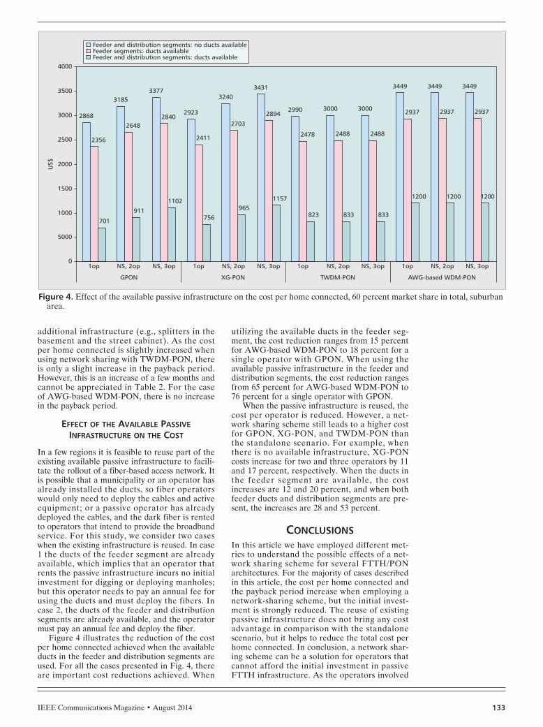
In a few regions it is feasible to reuse part of theexisting available passive infrastructure to facili-tate the rollout of a fiber-based access network. Itis possible that a municipality or an operator hasalready installed the ducts, so fiber operatorswould only need to deploy the cables and activeequipment; or a passive operator has alreadydeployed the cables, and the dark fiber is rentedto operators that intend to provide the broadbandservice. For this study, we consider two caseswhen the existing infrastructure is reused. In case1 the ducts of the feeder segment are alreadyavailable, which implies that an operator thatrents the passive infrastructure incurs no initialinvestment for digging or deploying manholes;but this operator needs to pay an annual fee forusing the ducts and must deploy the fibers. Incase 2, the ducts of the feeder and distributionsegments are already available, and the operatormust pay an annual fee and deploy the fiber.
Figure 4 illustrates the reduction of the costper home connected achieved when the availableducts in the feeder and distribution segments areused. For all the cases presented in Fig. 4, thereare important cost reductions achieved. When
utilizing the available ducts in the feeder seg-ment, the cost reduction ranges from 15 percentfor AWG-based WDM-PON to 18 percent for asingle operator with GPON. When using theavailable passive infrastructure in the feeder anddistribution segments, the cost reduction rangesfrom 65 percent for AWG-based WDM-PON to76 percent for a single operator with GPON.
When the passive infrastructure is reused, thecost per operator is reduced. However, a net-work sharing scheme still leads to a higher costfor GPON, XG-PON, and TWDM-PON thanthe standalone scenario. For example, whenthere is no available infrastructure, XG-PONcosts increase for two and three operators by 11and 17 percent, respectively. When the ducts inthe feeder segment are available, the costincreases are 12 and 20 percent, and when bothfeeder ducts and distribution segments are pre-sent, the increases are 28 and 53 percent.
CONCLUSIONSIn this article we have employed different met-rics to understand the possible effects of a net-work sharing scheme for several FTTH/PONarchitectures. For the majority of cases describedin this article, the cost per home connected andthe payback period increase when employing anetwork-sharing scheme, but the initial invest-ment is strongly reduced. The reuse of existingpassive infrastructure does not bring any costadvantage in comparison with the standalonescenario, but it helps to reduce the total cost perhome connected. In conclusion, a network shar-ing scheme can be a solution for operators thatcannot afford the initial investment in passiveFTTH infrastructure. As the operators involved
Figure 4. Effect of the available passive infrastructure on the cost per home connected, 60 percent market share in total, suburbanarea.
GPON
2868
2356
1op
701
3185
2648
NS, 2op
911
3377
2840
NS, 3op
1102
2923
2411
1op
756
3240
2703
NS, 2op
965
3431
2894
NS, 3op
1157
2990
2478
1op
823
3000
2488
NS, 2op
833
3000
2488
NS, 3op
833
3449
2937
1op
1200
3449
2937
NS, 2op
1200
3449
2937
NS, 3op
1200
5000
US$
1000
1500
2000
2500
3000
3500
4000
0
Feeder and distribution segments: no ducts availableFeeder segments: ducts availableFeeder and distribution segments: ducts available
XG-PON TWDM-PON AWG-based WDM-PON
SCHNEIR_LAYOUT.qxp_Layout 7/30/14 2:00 PM Page 133

IEEE Communications Magazine • August 2014134
in the market share arrangement will be compet-ing for the same subscribers, the market shareand revenues achieved by one operator will belower than those it could achieve if it deployedthe network in standalone mode.
REFERENCES[1] D. Katsianis et al., “Risks Associated with Next Genera-
tion Access Networks Investment Scenarios,” IEEE Net-work, vol. 26, no. 4, July/Aug. 2012, pp. 11–17.
[2] F. Effenberger et al., “An Introduction to PON Tech-nologies,” IEEE Commun. Mag., vol. 45, no. 3, Mar.2007, pp. S17–S25.
[3] J. Chen et al., “Cost vs. Reliability Performance Study ofFiber Access Network Architectures,” IEEE Commun.Mag., vol. 48, no. 2, Feb. 2010, pp. 56–65.
[4] K. Grobe et al., “Cost and Energy Consumption Analysisof Advanced WDM-PONs,” IEEE Commun. Mag., vol.49, no. 2, Feb. 2011, pp. s25–s32.
[5] C. Mas Machuca, J. Chen, and L. Wosinska, “Cost-Effi-cient Protection in TDM PONs,” IEEE Commun. Mag.,vol. 50, no. 8, Aug. 2012, pp. 110–17.
[6] S. Hoernig et al., “The Impact of Different Fibre AccessNetwork Technologies on Cost, Competition and Wel-fare,” Telecommun. Policy, vol. 36, no. 2, Mar. 2012,pp. 96–112.
[7] D. Breuer et al., “Opportunities for Next-GenerationOptical Access,” IEEE Commun. Mag., vol. 49, no. 2,Feb. 2011, pp. 16–24.
[8] M. Bourreau, C. Cambini, and S. Hoernig, “Ex-ante Reg-ulation and Co-investment in the Transition to NextGeneration Access,” Telecommun. Policy, vol. 36, no. 5,June 2012, pp. 399–406.
[9] J.P. Pereira and P. Ferreira, “Infrastructure Sharing as anOpportunity to Promote Competition in Local AccessNetworks,” J. Computer Networks and Commun., 2012.
[10] J. Rendon Schneir and Y. Xiong, “Economic Implica-tions of A Co-Investment Scheme for FTTH/PON Archi-tectures,” Telecommun. Policy, vol. 37, no. 10, Nov.2013, pp. 849–60.
[11] ITU-T G.698.3, SG15, “Multichannel Seeded DWDMApplications with Single-Channel Optical Interfaces,”Feb. 2012.
[12] ITU-T G.987.1, SG15, “10-Gigabit-Capable PassiveOptical Networks (XG-PON): General Requirements,”Jan. 2010.
[13] ITU-T G.989.1, SG15, “40-Gigabit-Capable PassiveOptical Networks (NG-PON2): General Requirements,”Mar. 2013.
[14] WIK-Consult, “The Economics of Next Generation Access— Final Report,” Study for ECTA, Bad Honnef, Germany,Sept. 2008; http://www.ectaportal.com/en/REPORTS/WIK-Studies/WIK-NGA-Study-2008/.
[15] Analysys Mason, “The Costs of Deploying Fibre-BasedNext-Generation Broadband Infrastructure,” FinalReport for the Broadband Stakeholder Group, Cam-bridge, U.K., Sept. 2008; http://www.broadbanduk.org/2008/09/05/bsg-publishes-costs-of-deploying-fibre-based-superfast-broadband/.
BIOGRAPHIESJUAN RENDON SCHNEIR ([email protected]) received hisPh.D. degree in telecommunications engineering fromthe Polytechnic University of Catalonia, Spain, in 2001.Currently, he collaborates with Huawei Technologies inWestern Europe on financial, regulatory, and strategicaffairs. Previously, he was senior consultant in the CostModelling and Internet Economics Department at WIK-Consult in Germany. He was an assistant professor in theDepartment of Information and Communication Tech-nologies at Pompeu Fabra University, Spain. He has alsobeen a visiting professor at ITAM University, Mexico, anda visiting researcher at Karlstad University, Sweden. Hepreviously worked for the telecommunications companiesTelefónica and Italtel. Currently, his research interestsinclude broadband deployment policies, technologyadoption, and f inancial and regulatory aspects oftelecommunications systems.
YUPENG XIONG leads the planning of FTTx solutions world-wide at the headquarters of Huawei Technologies in Chinaand was director of the European Fixed Access NetworkManagement Department in Western Europe. He receivedhis M.E. degree in telecommunication and electronics sys-tems from Xi’an Jiaotong University in 1998. He has accu-mulated 13 years of experience in fixed access technologies.During his stay in Europe, he worked with leading telecom-munications operators on FTTx solutions and was involvedin research on open access solutions. He has also devel-oped considerable insights into fixed broadband technolo-gies and the industry environment. Prior to this, he wassolution planning and system architect of fixed broadbandsolutions and products at Huawei Technologies in China.
As the operators
involved in the mar-
ket-share arrange-
ment will be
competing for the
same subscribers,
the market share
and the revenues
that will be achieved
by one operator will
be lower than the
ones that it could
achieve if it deployed
the network in
stand-alone mode.
SCHNEIR_LAYOUT.qxp_Layout 7/30/14 2:00 PM Page 134