COSPAS-SARSAT 406 MHz DISTRESS BEACON TYPE APPROVAL STANDARD · COSPAS-SARSAT 406 MHz DISTRESS...
88
_____________________________________ COSPAS-SARSAT 406 MHz DISTRESS BEACON TYPE APPROVAL STANDARD C/S T.007 Issue 3 - Revision 10 October 2003 _____________________________________
-
Upload
phungthuan -
Category
Documents
-
view
218 -
download
0
Transcript of COSPAS-SARSAT 406 MHz DISTRESS BEACON TYPE APPROVAL STANDARD · COSPAS-SARSAT 406 MHz DISTRESS...

_____________________________________
COSPAS-SARSAT 406 MHz DISTRESS BEACON TYPE APPROVAL STANDARD C/S T.007 Issue 3 - Revision 10 October 2003
_____________________________________

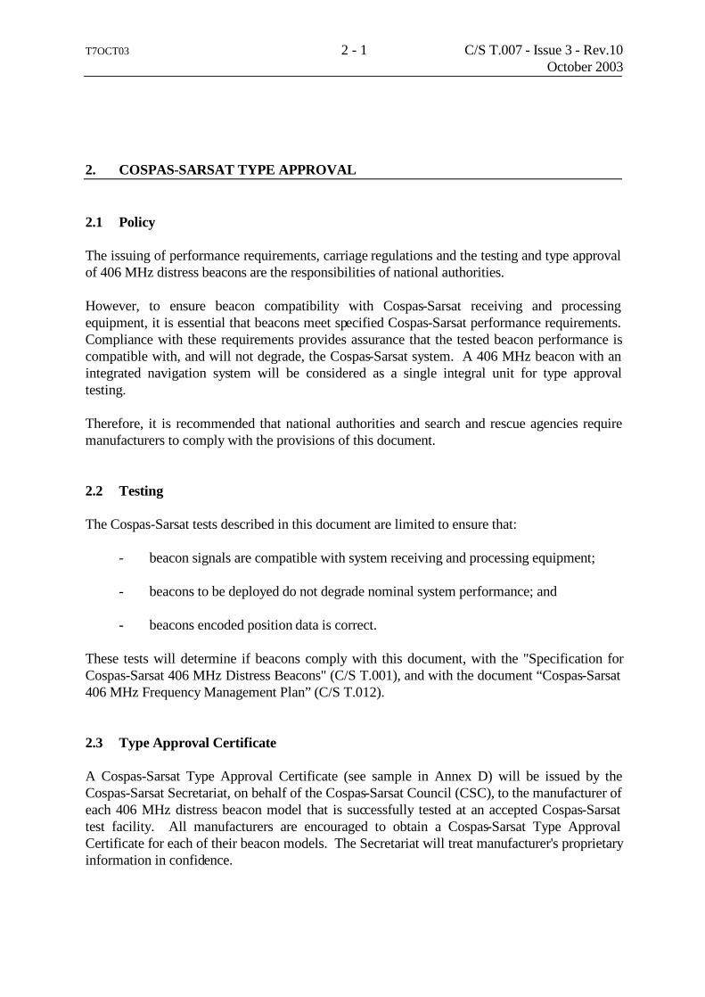
T7OCT03 i C/S T.007 - Issue 3 - Rev.10 October 2003 COSPAS-SARSAT 406 MHz DISTRESS BEACON TYPE APPROVAL STANDARD History Issue Revision Date Revised Pages Comments 1 0 Nov 87 Approved (CSSC-4/CSC-1) 2 0 Oct 89 Approved (CSC-3) 3 0 Dec 92 Approved (CSC-9) 3 1 Dec 93 i, ii, v, 1-1, 3-1, Approved (CSC-11) 6-1, A-1, A-2, A-11, B-5, B-7, B-9, C-1, C-7, C-9, C-10, E-1, F-1, F-2 3 2 Nov 95 i to v, 2-1, 4-2, 5-1, Approved (CSC-15) A-1, A-4, A-5, A-6, A-12, A-13, A-14, C-1, C-2, C-5, C-8, C-11, C-12 3 3 Oct 96 i, ii, iv, 2-1, 2-2, Approved (CSC-17) 3-1, 4-2, 5-1, 5-2, A-11, A-12 3 4 Oct 97 i, ii, 6-1, 6-2, E-1 Approved (CSC-19) 3 5 Oct 98 All pages reprinted Approved (CSC-21) 3 6 Oct 99 i to vi, 5-1, 5-2, Approved (CSC-23) A-3 to A-8, A-12 to A14, C-2, C-3, C-9, C-11, C-12, G-2 3 7 Oct 00 i, ii, iii, 6-3 to 6-6 A-14, C-12 Approved (CSC-25) 3 8 Oct 01 i to vi, 3-1, 3-2, Approved (CSC-27) 5-1 to 6-6, B-5, B-8 to B-16, C-1, C-11, E-1 to F-2, H-1 to I-2 3 9 Oct 02 i, ii, 1-1, 1-2, 2-1, 6-4, Approved (CSC-29) A-6, B-8, C-6 to C-12, D-1, D-2 3 10 Oct 03 i to vi, 2-1,2-2, 5-1, 5-2, Approved (CSC-31) 6-3, 6-4, A-1 to A-16, B-1 to B-10, C-1 to C-12, I-1, I-2, J-1, J-2

T7OCT03 ii C/S T.007 - Issue 3 - Rev.10 October 2003
LIST OF PAGES Page # Date of
latest revision
Page # Date of latest revision
Page # Date of latest revision
cover Oct 03 A-7 Oct 03 C-11 Oct 03 i Oct 03 A-8 Oct 03 C-12 Oct 03 ii Oct 03 A-9 Oct 03 iii Oct 03 A-10 Oct 03 D-1 Oct 02 iv Oct 03 A-11 Oct 03 D-2 Oct 02 v Oct 03 A-12 Oct 03 vi Oct 03 A-13 Oct 03 E-1 Oct 01 A-14 Oct 03 E-2 Oct 01 1-1 Oct 02 A-15 Oct 03 1-2 Oct 02 A-16 Oct 03 F-1 Oct 01 F-2 Oct 01 2-1 Oct 03 B-1 Oct 03 2-2 Oct 03 B-2 Oct 03 G-1 Oct 98 B-3 Oct 03 G-2 Oct 99 3-1 Oct 01 B-4 Oct 03 3-2 Oct 01 B-5 Oct 03 H-1 Oct 01 B-6 Oct 03 H-2 Oct 01 4-1 Oct 98 B-7 Oct 03 4-2 Oct 98 B-8 Oct 03 I-1 Oct 03 4-3 Oct 98 B-9 Oct 03 I-2 Oct 03 4-4 Oct 98 B-10 Oct 03 B-11 Oct 01 J-1 Oct 03 5-1 Oct 03 B-12 Oct 01 J-2 Oct 03 5-2 Oct 03 B-13 Oct 01 B-14 Oct 01 6-1 Oct 01 B-15 Oct 01 6-2 Oct 01 B-16 Oct 01 6-3 Oct 03 6-4 Oct 03 C-1 Oct 03 6-5 Oct 01 C-2 Oct 03 6-6 Oct 01 C-3 Oct 03 C-4 Oct 03 A-1 Oct 03 C-5 Oct 03 A-2 Oct 03 C-6 Oct 03 A-3 Oct 03 C-7 Oct 03 A-4 Oct 03 C-8 Oct 03 A-5 Oct 03 C-9 Oct 03 A-6 Oct 03 C-10 Oct 03

T7OCT03 iii C/S T.007 - Issue 3 - Rev.10 October 2003 TABLE OF CONTENTS Page 1. Introduction ...................................................................................................................... 1-1 1.1 Scope................................ ................................ ................................ ....................... 1-1 1.2 Reference documents ............................................................................................. 1-1 2. Cospas-Sarsat Type Approval ................................ ................................ ........................ 2-1 2.1 Policy ................................ ................................ ................................ ...................... 2-1 2.2 Testing .................................................................................................................... 2-1 2.3 Type Approval Certificate...................................................................................... 2-1 3. Testing Laboratories................................ ................................ ................................ ........ 3-1 3.1 Testing .................................................................................................................... 3-1 3.2 Cospas-Sarsat Accepted Test Facilities ................................ ................................ . 3-1 3.3 Testing of ELT Antennas Separated from Beacons............................................... 3-1 4. Cospas-Sarsat Testing Procedure................................ ................................ ................... 4-1 4.1 Sequence of Events ................................................................................................ 4-1 4.2 Initial Request................................ ................................ ................................ ......... 4-1 4.3 Test Units................................................................................................................ 4-2 4.4 Test Conditions....................................................................................................... 4-2 4.5 Test Procedure for Beacon with Operator Controlled Ancillary Devices............. 4-3 5. Technical Data .................................................................................................................. 5-1 6. Cospas-Sarsat Certification............................................................................................. 6-1 6.1 Approval of Results................................................................................................ 6-1 6.2 Future Changes....................................................................................................... 6-1 6.2.1 Alternative Batteries................................ ................................ ................... 6-2 6.2.2 Alternative Internal Navigation Device................................ ..................... 6-2 6.3 Modifications to Include Encoded Position Data from an External Navigation Device................................ ................................ ................................ .. 6-3 6.4 Changes to Frequency Generation ......................................................................... 6-3 6.4.1 Minor Changes to Frequency Generation.................................................. 6-3 6.4.2 Changes to Frequency Generation Which Might Affect Beacon Performance................................ ................................ ................................ 6-4 6.5 Alternative Names for a Type Approved Beacon.................................................. 6-5 ANNEX A: Beacon Measurement Specifications A1 General................................ ................................ ................................ .............................. A-1

T7OCT03 iv C/S T.007 - Issue 3 - Rev.10 October 2003
TABLE OF CONTENTS (Continued) Page A2 Tests Required ................................................................................................................ A-2 A2.1 Electrical and Functional Tests at Constant Temperature.............................. A-2 A2.2 Thermal Shock Test......................................................................................... A-2 A2.3 Operating Lifetime at Minimum Temperature ............................................... A-3 A2.4 Frequency Stability Test with Temperature Gradient................................ ..... A-4 A2.5 Satellite Qualitative Tests................................................................................ A-5 A2.6 Beacon Antenna Test................................ ................................ ....................... A-5 A2.7 Navigation System Test................................................................................... A-5 A2.8 Additional Protocols........................................................................................ A-5 A3 Measurement Methods ...............................................................................................A-6 A3.1 Message Format and Structure.....................................................................A-6 A3.1.1 Repetition Period .........................................................................................A-6 A3.1.2 Duration of the Unmodulated Carrier ..........................................................A-7 A3.1.3 Bit Rate and Stability ...................................................................................A-7 A3.1.4 Message Coding...........................................................................................A-7
A3.2 Modulator and 406 MHz Transmitter ..........................................................A-7 A3.2.1 Transmitted Frequency.................................................................................A-8 A3.2.1.1 Nominal Value .............................................................................................A-8 A3.2.1.2 Short-Term Stability ....................................................................................A-8 A3.2.1.3 Medium-Term Stability................................................................................A-9 A3.2.2 Transmitter Power Output..........................................................................A-10 A3.2.2.1 Transmitter Power Output Level................................................................A-10 A3.2.2.2 Transmitter Power Output Rise Time........................................................A-10 A3.2.2.3 Antenna Characteristics .............................................................................A-11 A3.2.2.4 Spurious Output .........................................................................................A-11 A3.2.3 Data Encoding and Modulation .................................................................A-11
A3.3 Voltage Standing-Wave Ratio ...................................................................A-12
A3.4 Protection Against Continuous Transmission............................................A-12
A3.5 Oscillator Aging.........................................................................................A-12
A3.6 Self-test Mode............................................................................................A-12
A3.7 Ancillary Electrical Devices in the Beacon................................................A-13 A3.7.1 Automatically Controlled Ancillary Devices.............................................A-13 A3.7.2 Operator Controlled Ancillary Devices .....................................................A-13
A3.8 Navigation System .....................................................................................A-13 A3.8.1 Position Data Default Values.....................................................................A-14 A3.8.2 Position Acquisition Time and Position Accuracy ....................................A-14 A3.8.3 Encoded Position Data Update Interval .....................................................A-14 A3.8.4 Position Clearance After Deactivation.......................................................A-14

T7OCT03 v C/S T.007 - Issue 3 - Rev.10 October 2003
TABLE OF CONTENTS (Continued) Page A3.8.5 Position Data Input Update Interval...........................................................A-15 A3.8.6 Last Valid Position.....................................................................................A-15 A3.8.7 Coarse Position and Delta Offset...............................................................A-15 ANNEX B: Antenna Characteristics B1 Scope .................................................................................................................B-1 B2 General Test Configuration ...............................................................................B-1 B3 Test Site .............................................................................................................B-2 B4 Ground Plane and Beacon Installation...............................................................B-2 B5 Measuring Antenna............................................................................................B-3 B6 Beacon Transmitting Antenna ...........................................................................B-5 B7 Radiated Power Measurements..........................................................................B-5 B8 Test Receiver Calibration ..................................................................................B-7 B9 Antenna Polarization Measurement...................................................................B-8 B10 Analysis of Results ............................................................................................B-9 B11 Antenna VSWR Measurement ..........................................................................B-9 ANNEX C: Type Approval Test Results Application for Cospas-Sarsat 406 MHz Beacon Type Approval Certificate .......................... C-1 406 MHz Beacon Self-Test Characteristics................................ ................................ ............... C-2 406 MHz Beacon Antenna Test Results .................................................................................... C-3 Summary of 406 MHz Beacon Test Results.............................................................................. C-5 ANNEX D: Cospas-Sarsat Type Approval Certificate................................ .................... D-1 ANNEX E: Change Notice Form................................ ................................ ........................ E-1 ANNEX F: Designation of Additional Names of a Cospas-Sarsat Type Approved 406 MHz Beacon Model................................ ...................... F-1 ANNEX G: Sample Procedure for Type Approval Testing of 406 MHz Beacons with Voice Transceiver ............................................. G-1 ANNEX H: Application for Testing Separated ELT Antenna(s) at an Independent Antenna Test Facility .................................................... H-1 ANNEX I: Request to Exclude ELT Antenna(s) from the Cospas-Sarsat Secretariat List of ELT Accepted Antennas .............................................. I-1 ANNEX J: Beacon Quality Assurance Plan.................................................................... J-1

T7OCT03 vi C/S T.007 - Issue 3 - Rev.10 October 2003
TABLE OF CONTENTS (Continued) Page LIST OF FIGURES: Figure A1: Temperature Gradient Showing Points A,B, tstart and tstop ................................ . A-4 Figure A2: Transmission Timing.......................................................................................... A-6 Figure A3: Definition of Measurement Intervals ................................................................. A-7 Figure A4: Medium-Term Frequency Stability Measurement................................ ........... A-10 Figure B1: Test Site Plan View ................................ ................................ ........................... B-11 Figure B2a: Equipment Test Set-Up for Beacon Antenna Test (for PLBs) ......................... B-12 Figure B2b: Equipment Test Set-Up for Beacon Antenna Test (for ELTs) .........................B-13 Figure B2c: Equipment Test Set-Up for Beacon Antenna Test (for EPIRBs) ..................... B-14 Figure B3a: Measuring Antenna Perpendicular to Direction of Propagation.......................B-15 Figure B3b: Measuring Antenna Not Perpendicular to Direction of Propagation ...............B-15 Figure B4: RF Measurement During Preamble...................................................................B-16 LIST OF TABLES: Table C1a: Effective Radiated Power / Antenna Gain..........................................................C-3 Table C1b: Induced Voltage Measurements ..........................................................................C-4 Table C2: Summary of 406 MHz Beacon Test Results.......................................................C-5

T7OCT17.02 1 - 1 C/S T.007 - Issue 3 - Rev.9 October 2002 1. INTRODUCTION 1.1 Scope This document defines the Cospas-Sarsat policy on type approval of 406 MHz distress beacons and describes: a) the procedure to apply for Cospas-Sarsat type approval of a 406 MHz distress
beacon, and b) the type approval test methods. 1.2 Reference Documents - Cospas-Sarsat Document C/S T.001, "Specification for Cospas-Sarsat 406 MHz
Distress Beacons". - Cospas-Sarsat Document C/S T.008, "Cospas-Sarsat Acceptance of 406 MHz
Beacon Type Approval Test Facilities". - Cospas-Sarsat Document C/S T.012, “Cospas-Sarsat 406 MHz Frequency
Management Plan”. - ITU-R M.633, "Transmission characteristics of a satellite emergency
position-indicating radio beacon (satellite EPIRB) system operating through a low polar-orbiting satellite system in the 406 MHz band".
-END OF SECTION 1-

T7OCT17.02 1 - 2 C/S T.007 - Issue 3 - Rev.9 October 2002
page left blank
T7OCT03 2 - 1 C/S T.007 - Issue 3 - Rev.10 October 2003 2. COSPAS-SARSAT TYPE APPROVAL 2.1 Policy The issuing of performance requirements, carriage regulations and the testing and type approval of 406 MHz distress beacons are the responsibilities of national authorities. However, to ensure beacon compatibility with Cospas-Sarsat receiving and processing equipment, it is essential that beacons meet specified Cospas-Sarsat performance requirements. Compliance with these requirements provides assurance that the tested beacon performance is compatible with, and will not degrade, the Cospas-Sarsat system. A 406 MHz beacon with an integrated navigation system will be considered as a single integral unit for type approval testing. Therefore, it is recommended that national authorities and search and rescue agencies require manufacturers to comply with the provisions of this document. 2.2 Testing The Cospas-Sarsat tests described in this document are limited to ensure that: - beacon signals are compatible with system receiving and processing equipment; - beacons to be deployed do not degrade nominal system performance; and - beacons encoded position data is correct. These tests will determine if beacons comply with this document, with the "Specification for Cospas-Sarsat 406 MHz Distress Beacons" (C/S T.001), and with the document “Cospas-Sarsat 406 MHz Frequency Management Plan” (C/S T.012). 2.3 Type Approval Certificate A Cospas-Sarsat Type Approval Certificate (see sample in Annex D) will be issued by the Cospas-Sarsat Secretariat, on behalf of the Cospas-Sarsat Council (CSC), to the manufacturer of each 406 MHz distress beacon model that is successfully tested at an accepted Cospas-Sarsat test facility. All manufacturers are encouraged to obtain a Cospas-Sarsat Type Approval Certificate for each of their beacon models. The Secretariat will treat manufacturer's proprietary information in confidence.

T7OCT03 2 - 2 C/S T.007 - Issue 3 - Rev.10 October 2003 The Cospas-Sarsat Type Approval Certificate itself does not authorize the operation or sale of 406 MHz beacons. National type acceptance and/or authorization may be required in countries where the manufacturer intends to distribute beacons. The Certificate is subject to revocation by the Cospas-Sarsat Council should the beacon type for which it was issued cease to meet the Cospas-Sarsat specification. - END OF SECTION 2 -

T7OCT25.01 3 - 1 C/S T.007 - Issue 3 - Rev.8 October 2001 3. TESTING LABORATORIES 3.1 Testing The tests described in this document consist of a series of laboratory technical tests and an outdoor functional test of the beacon transmitting to the satellite. Manufacturers are encouraged to conduct preliminary laboratory tests on their beacons, but are cautioned not to radiate signals to the satellite. If open air radiation of 406 MHz signals should be necessary, the manufacturer must coordinate and receive approval for the test from the appropriate national or regional MCC. Any such radiation must use the test protocol of the appropriate type and format. For example, test user-location protocol should be used for testing of beacons intended to be encoded with user-location protocol.
3.2 Cospas-Sarsat Accepted Test Facilities Certain test facilities are accepted by Cospas-Sarsat to perform Cospas-Sarsat type approval tests, as described in document C/S T.008. Accepted test facilities are entitled to perform tests on any 406 MHz distress beacon for the purpose of having a Cospas-Sarsat Type Approval Certificate issued by the Secretariat. A list of Cospas-Sarsat accepted test facilities is maintained by the Cospas-Sarsat Secretariat. Following successful testing of a beacon, the technical information listed in section 5 of this document should be submitted to the Cospas-Sarsat Secretariat, so that a Cospas-Sarsat Type Approval Certificate can be issued to the beacon manufacturer.
3.3 Testing of ELT Antennas Separated from Beacons Although the Cospas-Sarsat type approval policy is to consider only the complete beacon with its antenna (i.e. Cospas-Sarsat does not type approve specific beacon components), this policy is not strictly applicable to ELTs which can be approved for use with different aircraft antennas. In respect of antenna testing requirements provided in Annex B to this documents, testing ELT antenna at a reputable and independent test facility specialised in antenna measurements is acceptable subject to prior agreement by Cospas-Sarsat and provided that the test facility is accredited by recognised standardisation bodies responsible for type approval of electronic and electrical equipment. In such case, the testing application package should also include: a) written confirmation by the Cospas-Sarsat Representative of the country where the
facility is located (see Annex H) of the independence of the antenna testing facility from the beacon manufacturer;

T7OCT25.01 3 - 2 C/S T.007 - Issue 3 - Rev.8 October 2001 b) a letter from the test facility briefly describing their capability in respect of ELT
antenna testing to the requirements specified in applicable Cospas-Sarsat documents; and
c) the reference of the test facility accreditation by recognised standardisation bodies
responsible for type approval of electronic and electrical equipment in the facility�s country.
In all cases, the testing of the aircraft antenna, as described above, should be completed with VSWR measurement as described at Annex B, and satellite qualitative tests using a type approved ELT or the ELT submitted for type approval as described at Annex A.
- END OF SECTION 3 -

T7OCT30.98D 4 - 1 C/S T.007 - Issue 3 - Rev.5October 1998
4. COSPAS-SARSAT TESTING PROCEDURE
4.1 Sequence of Events
Typical steps to obtain a Cospas-Sarsat Type Approval Certificate for a new beacon are:
a) manufacturer develops a beacon;
b) manufacturer conducts preliminary testing in his laboratory;
c) manufacturer schedules testing at a Cospas-Sarsat accepted test facility;
d) test facility conducts* type approval tests (see Annex C);
e) manufacturer and/or test facility (as coordinated by the manufacturer) submits tothe Cospas-Sarsat Secretariat the information listed in section 5 of this document;
f) Secretariat and Cospas-Sarsat Parties review the test results and technical data;
g) Cospas-Sarsat Secretariat provides results of review to the manufacturer withinapproximately 30 days, and if approved, a Cospas-Sarsat Type ApprovalCertificate is subsequently issued.
4.2 Initial Request
An initial request to a test facility might need to be made several weeks prior to the desiredtesting date. Since the manufacturer may wish to send a representative to witness the tests andprovide assistance in operating the beacon, proper clearances should be made with the testfacility well in advance. The manufacturer should be prepared to provide the test facility with:
a) two beacons for testing purposes;
b) replacement batteries.
_____________________
* NOTE: Cost of the testing is to be borne by the manufacturer.

T7OCT30.98D 4 - 2 C/S T.007 - Issue 3 - Rev.5October 1998
4.3 Test Units
One test unit shall be a fully packaged beacon, similar to the proposed production beacons,operating on its normal power source and equipped with its proper antenna.
The second beacon shall be configured such that the antenna port can be connected to the testequipment by a coaxial cable terminated by a 50-Ohm load. All necessary signal or controldevices should be provided by the beacon manufacturer to simulate nominal operation of allancillary devices of the beacon, such as external navigation input signals and manual control, inaccordance with A3.7, while in an environmental test chamber. The means to operate thesedevices in an automated and programmable way should be also provided by the manufacturer.
The test units shall be coded with the test protocol of appropriate type and format and shallmeet the requirements of C/S T.001. It should be noted that:
- the test unit subjected to the Cospas-Sarsat tests remains the property of themanufacturer. All information marked as proprietary shall be treated as such.
- the organization performing the Cospas-Sarsat tests bears no responsibility foreither the manufacturer's personnel or equipment.
- the manufacturer shall certify that the units submitted for test contain nohazardous components. The testing organization may choose not to test units thatit regards as hazardous.
If a beacon is to receive certification for additional location protocol types, means of changingthe protocol type shall be provided. Alternatively, this can be satisfied with additional testunits.
If a beacon is to receive certification for standard location protocol and/or the national locationprotocol, the unit used for the tests listed in A.2 shall be coded with one of these protocols.
4.4 Test Conditions
Tests shall be conducted by facilities accepted by Cospas-Sarsat. It is advisable that themanufacturer, or his representative, witness the tests.
The tests shall be carried out on the test beacon with its own power source. Test results shouldbe presented on the forms shown in Annex C of this document, along with additional graphs asnecessary. Tests shall demonstrate compliance with C/S T.001 and comprise the followingelements:
a) operating life and performance measurements at the beacon's minimum specifiedoperating temperature;

T7OCT30.98D 4 - 3 C/S T.007 - Issue 3 - Rev.5October 1998
b) performance measurements at room ambient temperature;
c) performance measurements at the beacon's maximum specified operatingtemperature;
d) performance measurements during the thermal gradient;
e) performance measurements beginning 15 minutes after thermal shock andactivation;
f) antenna measurements; and
g) a qualitative performance test through the satellites.
At the discretion of the test authority, the manufacturer may be required to replace thebatteries between these phases. However, no other modifications to the beacon will beallowed during the test period without a full re-test.
Beacons with multiple modes of operation shall have their 406 MHz characteristics measuredin each operating mode. The mode that draws maximum battery energy shall be tested to thefull range of the test requirements. If any other operating mode exhibits a pulse load which isgreater than the mode that draws maximum battery energy, this mode shall also undergo theoperating lifetime test. Approved measurement methods are described in Annexes A and B ofthis document, although other appropriate methods may be used by the testing authority toperform the measurements. These shall be fully documented in a technical report along withthe test results.
4.5 Test Procedure for Beacon with Operator Controlled Ancillary Devices
A unique test procedure may need to be defined for beacons with operator controlled ancillarydevices to characterise the possible impact of these devices on the beacon performance. Suchtest procedure shall follow the guidelines provided at section A3.7.2. A typical procedure fora beacon with a voice transceiver is provided at Annex G as an example of the guidelinesimplementation.
Unique test procedures for beacons with operator controlled ancillary device shall be:
a) coordinated between the beacon manufacturer and a Cospas-Sarsat type approvalfacility;

T7OCT30.98D 4 - 4 C/S T.007 - Issue 3 - Rev.5October 1998
b) submitted to the Cospas-Sarsat Secretariat for review prior to type approvaltesting at the Cospas-Sarsat type approval facility; and
c) approved by the Cospas-Sarsat Parties as appropriate.
- END OF SECTION 4 -

T7OCT03 5 - 1 C/S T.007 - Issue 3 - Rev.10 October 2003 5. TECHNICAL DATA The technical data submitted to the Cospas-Sarsat Secretariat must include at least the following: a) an application form (page C-1) for a Cospas-Sarsat Type Approval Certificate,
listing details of beacon, signed by the Cospas-Sarsat accepted test facility confirming that the beacon was tested in accordance with C/S T.007 and complies with C/S T.001;
b) beacon operating instructions and a technical data sheet; c) brochure or photograph of the beacon; d) statement of the specified operating temperature range of the beacon (maximum
and minimum temperatures) (see Annex C); e) descriptions, complete with diagrams as necessary, to demonstrate that the design:
• meets the requirement that the probability of any two beacons having an identical repetition period sequence is less than 0.001 (see section A3.1.1),
• provides protection against continuous transmission (see section A3.4),
• meets the frequency stability requirements over 5 years (see section A3.5),
• provides protection from repetitive self-test mode transmissions (see section A3.6);
f) a technical description and analysis of the matching network supplied for testing
purposes per section A.1; g) a list of the special features in the beacon (homer, strobe light, etc., see Annex C); h) a description of the "self-test" mode (see Annex C); i) a complete description of the power source, including, battery manufacturer's
name(s), cell manufacturer name, cell chemistry, number and type of cells, and electric diagram of the battery pack;
j) the technical data sheet of the reference oscillator, including oscillator type and
specifications; k) a summary of test results of the beacon and antenna, with supporting test data,
graphs and tables, as designated in Annexes A, B and C;
T7OCT03 5 - 2 C/S T.007 - Issue 3 - Rev.10 October 2003 l) a print out of sample messages generated by the beacon coding software providing
the beacon 15 Hex ID, for each coding option applicable to that beacon model with encoded identification representative of a real ID (e.g. not all “1” or “0”) for the nominal and the self-test modes (see Annex C, Table C2, section 16);
m) for beacons with internal navigation device a statement that GNSS cold start is
forced at every beacon activation (self-test, nominal), i.e. that no time dependent or position dependent data is stored in the memory of the GNSS device;
n) for beacons designed to transmit encoded position data, technical data showing that
the design incorporates a protection mechanism to ensure the 406 MHz signal is not degraded by a malfunction of the navigation device or a failure of the navigation device to acquire valid data;
o) for beacons designed to transmit encoded position data, sample messages to
demonstrate correct position data encoding, including initial coarse position, the delta offset, and overrange limits in the positive and negative direction (see section A3.8.7);
p) a copy of the beacon label; q) for ELT separated antennas, a statement of the beacon manufacturer if they do not
want to have their own antenna included on the Secretariat-maintained list of accepted ELT antennas (for antennas of their own design and having their own part number, see Annex I); and
r) the beacon quality assurance plan (see Annex J). For separated ELT antennas, the test results requested under (k) above may be replaced by a reference to the proper entry in the Secretariat-maintained list of accepted antennas*, along with an analysis showing that the ERP of the beacon-antenna combination would be within the limits specified in Section B10 of Annex B. The analysis must address the actual measured beacon output power and power loss factor. This does not modify the requirement for the provision of a full operational configuration defined in section 4.3 and for performing and reporting the satellite tests and VSWR tests. -------------- * Note: The measurement results of parameters for antennas included in the Secretariat list are kept on file at the
Cospas-Sarsat Secretariat and are available upon request.
- END OF SECTION 5 -

T7OCT25.01 6 - 1 C/S T.007 - Issue 3 - Rev.8 October 2001 6. COSPAS-SARSAT CERTIFICATION 6.1 Approval of Results To receive a Cospas-Sarsat Type Approval Certificate, a beacon shall have been demonstrated to meet the requirements of C/S T.001. The technical data and test results will be reviewed by the Cospas-Sarsat Secretariat and then, if found satisfactory, submitted to the Cospas-Sarsat Parties for approval. The results of this process will be conveyed to the manufacturer within approximately 30 days. If the unit is deemed to have passed the tests, the Secretariat will subsequently issue a Cospas-Sarsat Type Approval Certificate on behalf of the Cospas-Sarsat Council. The technical data and test results will be retained on file at the Secretariat. 6.2 Future Changes The manufacturer must advise the Cospas-Sarsat Secretariat (see Annex E) of any future changes to the design or production of the beacon or power source, which might affect beacon performance. For minor modifications to the beacon, factory test results provided to the Secretariat by the manufacturer can be considered on a case-by-case basis. These test results will be reviewed by the Secretariat, in consultation with the test facility which conducted the original type approval tests on the beacon, and the manufacturer will be advised if there is a need for further testing. Once a beacon incorporating a particular type of battery and /or an internal navigation device (such as a GPS or GLONASS engine) has been successfully tested at a Cospas-Sarsat test facility, and type approved by Cospas-Sarsat, subsequent upgrades to that battery or navigation device are permitted without further type approval testing at a Cospas-Sarsat test facility, provided the beacon manufacturer demonstrates that the changes do not degrade the performance of the 406 MHz beacon, as described below. If a beacon manufacturer wishes to make changes to the type of battery or the internal navigation device after the beacon has been Cospas-Sarsat type approved, the change notice form in Annex E must be completed and submitted to the Secretariat, together with factory test data confirming that the substitute battery or navigation device is at least technically equivalent to that used when the beacon was type approved. The Cospas-Sarsat type approval certificate will not be amended to include the alternative battery or navigation device in such cases, unless the beacon was partially retested at a Cospas-Sarsat type approval test facility.

T7OCT25.01 6 - 2 C/S T.007 - Issue 3 - Rev.8 October 2001
6.2.1 Alternative Batteries 6.2.1.1 The factory tests to be performed on the 406 MHz beacon with a type of
battery that has not been used in previous models tested at a Cospas-Sarsat type approval facility are:
i) electrical tests at the three constant temperatures (maximum, minimum and
ambient), excluding spurious output, VSWR and self-test (section A2.1); ii) thermal shock test (section A2.2); and iii) operating lifetime at minimum temperature (section A2.3).
The beacon manufacturer shall also submit technical data sheets describing the new battery.
6.2.1.2 If the alternative battery has been previously used in at least two beacon models
for testing at a Cospas-Sarsat type approval test facility, the factory tests to be performed on the 406 MHz beacon with the alternative batteries are:
i) electrical tests at ambient temperature excluding digital message, digital
message generator, modulation, spurious output, VSWR check, self-test mode (section A2.1); and
ii) operating lifetime at minimum temperature, excluding digital message
(section A2.3).
In both cases the beacon manufacturer shall also provide a written confirmation that the general performance of the 406 MHz beacon is not degraded using the alternative battery, and that the alternative battery is at least technically equivalent to the battery in the beacon originally type approved.
6.2.2 Alternative Internal Navigation Device
For a change to the internal navigation device, the beacon manufacturer shall provide test and analysis results confirming that:
i) the load on the beacon battery will not be more than when the beacon was initially type approved;
ii) the interface between the navigation device and the beacon is still
compatible; and iii) the performance of the 406 MHz beacon is not degraded.

T7OCT03 6 - 3 C/S T.007 - Issue 3 - Rev.10 October 2003 6.3 Modifications to Include Encoded Position Data from an External Navigation Device 6.3.1 A type approved beacon modified to accept position data from an external
navigation device shall be tested with the test protocol of appropriate type and format at a Cospas-Sarsat type approval facility. The tests to be performed shall consist of:
i) electrical tests at ambient and maximum temperatures but excluding
modulation, spurious output, and VSWR check (section A2.1); ii) operating lifetime at minimum temperature (section A2.3); iii) navigation system test (section A2.7); and iv) beacon coding software (item 16 of Table C2).
In addition, the beacon manufacturer shall also provide technical data sheets describing the navigation interface unit.
6.3.2 In the case of a subsequent change of the beacon navigation interface unit, the
beacon manufacturer shall provide tests and analysis results confirming that:
i) the load on the beacon battery will not be more than when the beacon was initially type approved;
ii) the interface between the navigation device and the beacon is still
compatible; and iii) the performance of the 406 MHz beacon is not degraded.
6.4 Changes to Frequency Generation 6.4.1 Minor Changes to Frequency Generation
In the case of oscillator replacement by an identical oscillator (on the basis of oscillator manufacturer data and written assurance) and when no other changes are required to beacon electronics or firmware, or in the case of a change of frequency of the beacon when this is achieved by modification of the oscillator (tuning or replacement of the oscillator crystal by a crystal of the same type) which does not involve significant changes to the oscillator performance, or in the case of a type approved beacon using a frequency synthesiser, the modification of the beacon can be considered as minor. Factory tests verifying the beacon performance can be accepted after consideration by the Secretariat on a case-by-case basis.

T7OCT03 6 - 4 C/S T.007 - Issue 3 - Rev.10 October 2003 6.4.1.1 In the case of a change of frequency, if the modification of the oscillator is
limited to the replacement of the crystal by a crystal of the same type, or tuning the oscillator by the oscillator manufacturer, or reprogramming of the frequency synthesiser, the factory testing should include: - measurement of absolute value of the beacon 406 MHz transmitted carrier
frequency at ambient temperature. 6.4.1.2 In the case of oscillator replacement with an identical oscillator1 and no other
changes are required to the beacon electronics, or in the case of a change of frequency if the modification includes changes to circuits external to the frequency oscillator/synthesiser (e.g., an external trimmer), the factory tests should include (with reference to Table C2): - item 5: 406 MHz transmitted frequency, - item 9: thermal shock, except transmitted power and digital message, - item 11: temperature gradient, except transmitted power and digital message.
6.4.1.3 In both cases (6.4.1.1 and 6.4.1.2 above) the technical file should be submitted
to the Secretariat including at least the following:
a) a change notice form (E1) specifying the details of frequency generation change;
b) the measurement results of required tests; and
c) a technical data sheet describing the oscillator, including: - oscillator type - oscillator specifications - assurance of oscillator manufacturer that the specification of the old and
new oscillators are identical, except for the frequency, as appropriate, in the form of a detailed statement.
6.4.2 Changes to Frequency Generation which Might Affect Beacon Performance
If the alternative oscillator has different parameters, or alternative technology is used to generate the RF frequency (e.g. frequency synthesiser), or additional changes are required to the beacon electronics or firmware, the modified beacon should be re-tested at a Cospas-Sarsat accepted facility. The testing should include (with reference to Table C2): - item 5: 406 MHz transmitted frequency, - item 9: thermal shock, - item 10: operating lifetime at minimum temperature, - item 11: temperature gradient, except transmitted power and digital message,
_______________________ 1 For the purpose of the Cospas-Sarsat type approval a replacement oscillator can be considered to be identical
to the original oscillator if they have the same circuitry, packaging, physical dimensions and firmware (as applicable) and the replacement reference oscillator has electrical and mechanical parameters that are equal to, or better than, those of the original oscillator.
T7OCT25.01 6 - 5 C/S T.007 - Issue 3 - Rev.8 October 2001
- item 12: long term frequency stability, - item 14: satellite qualitative tests. The technical data submitted to the Cospas-Sarsat Secretariat should include at least the following:
a) application form (page C-1) for Cospas-Sarsat Type Approval Certificate, listing details of beacon, the details of frequency generation change signed by the Cospas-Sarsat accepted test facility confirming that the beacon was tested in accordance with C/S T.007 and complies with C/S T.001;
b) beacon technical data sheet;
c) statement of the specified operating temperature range of the beacon (maximum and minimum temperatures);
d) descriptions, complete with diagrams as necessary, to demonstrate that the design meets the long term frequency stability requirement;
e) the measurement results as specified above; and
f) technical data sheet describing the oscillator, including - oscillator type, - oscillator specifications.
6.5 Alternative Names for a Type Approved Beacon If a beacon manufacturer wishes to have the type approved beacon designated under alternative names (e.g., agent/distributor's name and model number), Annex F of this document should be completed and sent to the Secretariat.
- END OF SECTION 6 -

T7OCT25.01 6 - 6 C/S T.007 - Issue 3 - Rev.8 October 2001
page left blank

T7OCT30.98D C/S T.007 - Issue 3 - Rev.5October 1998
ANNEXESTO THE COSPAS-SARSAT
406 MHz DISTRESS BEACONTYPE APPROVAL STANDARD

T7OCT30.98D C/S T.007 - Issue 3 - Rev.5October 1998
page left blank

T7OCT03 A - 1 C/S T.007 - Issue 3 - Rev.10 October 2003 ANNEX A
BEACON MEASUREMENT SPECIFICATIONS A1 GENERAL The tests required by Cospas-Sarsat for 406 MHz beacon type approval are described in this Annex and Annex B, giving details on the parameters, defined in C/S T.001, which must be measured during the tests. All measurements must be performed with equipment and instrumentation which is in a known state of calibration, and with measurement traceability to National Standards. The measurement accuracy requirements for Cospas-Sarsat accepted test facilities are given in Annex A of C/S T.008. These measurement accuracies should be added to the beacon specification limits of C/S T.001 (thereby allowing a slight extra margin) when considering test results which are near the specification limit. All measurement methods used by Cospas-Sarsat accepted test facilities (as defined in C/S T.007) must be approved by Cospas-Sarsat to ensure the validity and repeatability of test data. In general, the test equipment used must be capable of: - measuring the power that would be accepted by the antenna while the power is
directed to a 50 Ohm load. An impedance matching network is to be provided for the test period by the beacon manufacturer. The matching network shall present a 50 Ohm impedance to the dummy load and shall present to the beacon power amplifier output the same impedance as would be present if the antenna were in place (the matching network is not required if the beacon power amplifier nominal output impedance is 50 Ohm and the beacon antenna VSWR measured relative to 50 Ohm is within the 1.5:1 ratio);
- determining the instantaneous phase of the output signal and making amplitude and
timing measurements of the phase waveform; - interpreting the phase modulation to determine the value of the encoded data bits; - measuring the frequency of the output signal; - producing gating signals synchronized with various features of the signal modulation; - maintaining the beacon under test at specified temperatures and temperature gradients
while performing all other functions stated; - providing appropriate navigation input signals, if applicable; and - measuring the radiated power level, as described in Annex B.

T7OCT03 A - 2 C/S T.007 - Issue 3 - Rev.10 October 2003 A suggested sequence for performing the tests described herein is shown in Table C2 of Annex C, but the tests may be performed in any other convenient sequence. The test results are to be summarized and reported as shown in Annex C, with appropriate graphs attached as indicated. A2 TESTS REQUIRED A2.1 Electrical and Functional Tests at Constant Temperature (test no. 1 to 8 in
Annex C) The tests specified in para. A3.1 through para. A3.3 (except A3.2.2.3, antenna tests) are performed after the beacon under test, while turned off, has stabilized for a minimum of 2 hours at laboratory ambient temperature, at the specified minimum operating temperature, and at the maximum operating temperature. The beacon is then allowed to operate for 15 minutes before measurements are started to measure the following parameters at each of the three constant temperatures:
• transmitter power output, per para. A3.2.2 (except A3.2.2.3 antenna tests) • digital message, per para. A3.1.4 • digital message generator, per para. A3.1, A3.1.1, A3.1.2 and A3.1.3 • modulation, per para. A3.2.3 • transmitted frequency, per para. A3.2.1 • spurious output, per para. A.3.2.2.4 • VSWR check, per para. A3.3 • self-test mode, per para. A3.6
A2.2 Thermal Shock Test (test no. 9 in Annex C) The beacon under test, while turned off, is to stabilize at a selected temperature in its operating range. The beacon is then simultaneously placed into an environment held at 30 degrees C offset from the initial temperature and turned on. The beacon is then allowed to operate for 15 minutes before measurements are started to measure the following parameters:
• transmitted frequency, per para. A3.2.1 • transmitter power output, per para. A3.2.2.1 • digital message, per para. A3.1.4
Frequency measurements are made continually for two hours. Stability analysis is performed for these frequency samples as in para. A3.2.1. The 18-sample analysis window of the stability calculations is advanced in time through the period such that each succeeding data set includes the latest frequency sample and drops the earliest one. Power output per para. A3.2.2.1 and digital message checks per para. A3.1.4 are also made continually throughout the two-hour period.

T7OCT03 A - 3 C/S T.007 - Issue 3 - Rev.10 October 2003 A2.3 Operating Lifetime at Minimum Temperature (test no. 10 in Annex C) The beacon under test is operated at its minimum operating temperature for its rated life. During this period, the following parameters are measured on each transmission:
• transmitted frequency, per para. A3.2.1 • transmitter power output, per para. A3.2.2.1 • digital message, per para. A3.1.4
The 18-sample analysis window of the stability calculations is advanced in time through the period such that each succeeding data set includes the latest frequency sample and drops the earliest one. If beacon is intended to be encoded with short or long format messages, this test should be performed with a long format message. The operational lifetime test is intended to establish, with reasonable confidence, that the beacon will function at its minimum operating temperature for its rated life using a battery that has reached its expiration date. To accomplish this, the lifetime test of a beacon with its circuits powered from the beacon battery prior to beacon activation should be performed with a fresh battery pack which has been discharged to take into account: a) the average current drain resulting from constant operation of the circuits powered
from the beacon battery prior to beacon activation over the rated life of the battery pack (see note);
b) the number of self tests, as recommended by the beacon manufacturer over the rated life of the battery pack (the beacon manufacturer should substantiate the method used to determine the corresponding current drain); and
c) a correction coefficient of 1.65 (applied to item a and item b) to account for differences between battery to battery, beacon to beacon and the possibility of exceeding the battery replacement time.
After the battery pack has been appropriately discharged, the beacon is tested at its minimum operating temperature for its rated life as indicated above. Discharge of the battery may be replaced by the equivalent extension of the operating lifetime test. ______________________________________ Note: The beacon manufacturer should provide data necessary to discharge a fresh battery pack at room
temperature to account for current drain over the battery pack rated life time. The battery discharge figures provided by the beacon manufacturer should be verified by the testing laboratory, using an integrating charge meter which measures the total charge delivered to the inactivated test beacon in conjunction with the active circuits, over a sufficient period of time (supplied by the beacon manufacturer). This total measured charge, divided by the time recorded for the charge measurement, is the average current drain on the battery over the measurement time period which should be prorated to the rated life of the battery pack. The duration of the average current drain measurement should be defined by the testing laboratory.

T7OCT03 A - 4 C/S T.007 - Issue 3 - Rev.10 October 2003 A2.4 Frequency Stability Test with Temperature Gradient ( test no. 11 in Annex C) The beacon under test, while turned off, is to stabilize for 2 hours at the minimum specified operating temperature. It is then turned on and subjected to temperature gradient specified in Figure A1 below, during which time the following tests are performed continually on each burst:
• transmitted frequency, per para. A3.2.1 • transmitter power output, per para. A3.2.2.1 • digital message, per para. A3.1.4
The 18-sample analysis window of the stability calculations is advanced in time through the period such that each succeeding data set includes the latest frequency sample and drops the earliest one. When a battery replacement is required, two separate tests are performed. The up-ramp test is from tstart to point B (see Figure A1) and the down-ramp test is from point A to tstop. Before point A of the down-ramp, the beacon under test, while turned off, is to stabilize for 2 hours at +55°C and is then turned on and allowed a 15 minute warm-up period.
NOTES: Tmin = - 40°C (Class 1 beacon) Tmin = - 20°C (Class 2 beacon) ton = beacon turn-on time after 2 hour “cold soak” tmeas = start time of frequency stability measurement (ton + 15 min) Figure A1: Temperature gradient showing points A, B, tstart and tstop
+55 2h
1h 2h 2h
ton TIME tmeas
twarm-up = 15 min
Tmin
tstart tstop
A B

T7OCT03 A - 5 C/S T.007 - Issue 3 - Rev.10 October 2003 A2.5 Satellite Qualitative Tests (test no. 14 in Annex C) This test is to be performed only in coordination with the cognizant Cospas-Sarsat Mission Control Centre (MCC) and local authorities. The beacon should operate in its nominal configuration, if possible. However, if the beacon includes a homing transmitter operating on a distress frequency (e.g. 121.5 MHz or 243 MHz), this transmitter may need to be disabled or offset from the distress frequency for this test, as per the national requirements of the test facility. This test is to be performed in an environment which approximates, as closely as practicable, the intended use of the beacon. The test beacon must have its own antenna connected and must be coded with a test protocol of appropriate type and format (see sections 4.3 and A3.1.4). The beacon is operated in the open during at least 3 satellite passes and downlink data is checked for correctness of:
• location data computed by the LUT • digital message, per para. A3.1.4
The beacon must be successfully located and identified by a Cospas-Sarsat LEOLUT. Successful completion of this test is to be indicated by a "√" in the Table C2 of Annex C, and a summary of the results is to be attached to the Table. A2.6 Beacon Antenna Test (test no. 15 in Annex C) The beacon antenna test, described in section A3.2.2.3 and Annex B, is performed at the ambient temperature of the test facility and a correction factor is applied to the data to calculate the radiated power at minimum temperature at the end of the operating lifetime. This test must be performed using the non-modified test beacon, including the navigation antenna, if applicable. A2.7 Navigation System Test, if Applicable (test no. 17 in Annex C) For beacons incorporating the optional capability to transmit encoded position data, some additional tests, described in section A3.8, are required to verify the beacon output message, including the correct position data, BCH error-correcting code(s), default values, and update rates, if applicable. The navigation input system must be operating for the duration of all tests to ensure that it does not affect the 406 MHz signal and that the beacon can operate for the required operating lifetime. The beacon output digital message is monitored during all tests, as described in section A3.1.4. A2.8 Additional Protocols (test no. 18 in Annex C) If the beacon is capable of operating with protocol types not tested under A2.1, A2.2, A2.3, A2.4, and A2.5, the digital message for each protocol type shall be verified at ambient temperature according to A3.1.4. These should also include the self-test mode.

T7OCT03 A - 6 C/S T.007 - Issue 3 - Rev.10 October 2003 For location protocols verification of 2 messages with encoded position data is required, the second message shall be provided with encoded position at least 5 km from the first position. The verification of the digital message does not require a change of location of the beacon. A3 MEASUREMENT METHODS A3.1 Message Format and Structure The repetition period TR and the duration of the unmodulated carrier T1 are illustrated in Figure A2. (Note: many of the following measurements can be performed on the same set of 18 bursts.) Figure A2 : Transmission Timing
A3.1.1 Repetition Period The repetition period, TR , between the beginnings of two successive transmissions (see Figure A2) shall be randomised over the range of 47.5 to 52.5 seconds. 18 successive measurements shall be made and the difference between the maximum and minimum repetition periods shall be more than 1 second. The average repetition period shall be 50s ± 1.5s. The standard deviation of the 18 values of TR shall be between 0.5 and 2.0 seconds. The standard deviation, average, maximum and minimum values of TR are to be recorded in the Table C2 of Annex C. Additionally, the manufacturer shall show by analysis that the probability of any two of the manufacturer’s beacons having an identical TR sequence is less than 0.001.
BIPHASE SIGNAL
TR T1
PN 0.9 PN
TRANSMISSION SIGNAL AFTER DETECTION

T7OCT03 A - 7 C/S T.007 - Issue 3 - Rev.10 October 2003 A3.1.2 Duration of the Unmodulated Carrier The unmodulated carrier duration, T1, between the beginning of a transmission and the beginning of the data modulation (see Figure A2) shall satisfy the following relationship, where the values are derived from 18 successive measurements, and all values must be such that:
158.4 ms < T1 < 161.6 ms
The maximum and minimum values of T1 are to be recorded in the Table C2 of Annex C. A3.1.3 Bit Rate and Stability The bit rate, fb , in bits per second (bps) which is measured over at least the first 15 bits of one transmission, shall satisfy the following relationship, where the values of fb are derived from 18 successive measurements and all values must be such that:
396 bps < fb < 404 bps
The maximum and minimum values of fb are to be recorded in the Table C2 of Annex C. A3.1.4 Message Coding The content of the demodulated digital message shall be checked for validity and compliance with the format for each data field, bit by bit, and the BCH error correcting code(s) shall be checked for correctness. The content of the digital message shall be monitored during all tests for the protocol selected according to section 4.3. A3.2 Modulator and 406 MHz Transmitter The S1 pulse starts 12 ms after the beginning of the unmodulated carrier. The S2 pulse starts at the beginning of bit 23. The S3 pulse starts not later than 15 ms after the end of S2.
Figure A3 : Definition of Measurement Intervals
≤15 ms 12 ms
S1 S2 S3
~100 ms ~100 ms ~100 ms
UNMODULATED CARRIER
MODULATED CARRIER
TRANSMITTED SIGNAL PN
0.1 PN

T7OCT03 A - 8 C/S T.007 - Issue 3 - Rev.10 October 2003 A3.2.1 Transmitted Frequency Frequency measurements are made during each transmission, either directly at 406 MHz or at a stable downconverted frequency, during various intervals of approximately 100 milliseconds, as shown in Figure A3. The various frequency and frequency stability computations defined hereunder can all be made using data collected from the same set of 18 transmissions. A3.2.1.1 Nominal Value The mean transmission frequency, f0, is determined from 18 measurements of fi(1) made during the interval S1 during 18 successive transmissions, as follows: where n=18 A3.2.1.2 Short-Term Stability The short-term frequency stability is derived from measurements* of fi
(2) and fi(3) made during
the intervals S2 and S3 during 18 successive transmissions, as follows: where n=18 The above relationship corresponds to the Allan variance. The measurement conditions used here are different (i.e. dead time between two measurements). Experience, however, has shown that the results obtained are very close to those achieved under the normal measurement conditions for the Allan variance. --------------------------- * Note: To correctly measure the short-term frequency stability, it is essential that an equal number of positive
and negative phase transitions are included in the gating intervals defined as S2 and S3 in Figure A3, hence these intervals are only approximately 100 ms duration.
f fn
f ii
n
01 1
1
1= =
=∑( ) ( )
σ100
2 3
21
2 1 21
2msi i
ii
n
nf f
f=
−
=∑
( ) ( )
( )
/

T7OCT03 A - 9 C/S T.007 - Issue 3 - Rev.10 October 2003 A3.2.1.3 Medium-Term Stability The medium-term frequency stability is derived from measurements of fi(2) made over 18 successive transmissions at instants ti (see Figure A4). For a set of n measurements*, the medium-term frequency stability is defined by the mean slope of the least-squares straight line and the residual frequency variation about that line. The mean slope is given by: where n=18 The ordinate at the origin of the least-squares straight line is given by: where n=18 The residual frequency variation is given by: where n=18 ___________________ * With a transmission repetition period of approximately 50 seconds, there will be 18 measurements during an
approximate 15 minute period (i.e. n=18).
An t f t f
n t t
i ii
n
ii
n
ii
n
ii
n
ii
n=
−
−
= = =
= =
∑ ∑ ∑
∑ ∑1 1 1
2
1 1
2
Bf t t t f
n t t
ii
n
ii
n
ii
n
i ii
n
ii
n
ii
n=
−
−
= = = =
= =
∑ ∑ ∑ ∑
∑ ∑1
2
1 1 1
2
1 1
2
( )σ = − −
=∑1 2
1
1 2
n f At Bi ii
n /

T7OCT03 A - 10 C/S T.007 - Issue 3 - Rev.10 October 2003
Figure A4* : Medium-Term Frequency Stability Measurement * Figure not to scale A3.2.2 Transmitter Power Output A3.2.2.1 Transmitter Power Output Level The transmitter power output level is measured at the transmitter output. During output power measurement, the antenna is replaced by a dummy load that presents to the transmitter an impedance equal to that of the antenna under normal operation conditions. The RF losses of any impedance matching network which is connected to the beacon only for test purposes shall be accounted for in the power output measurement. A3.2.2.2 Transmitter Power Output Rise Time The transmitter power output rise time may be determined on an oscilloscope by measuring the rise time of the burst envelope from the 10% power point to the 90% power point. The power output level, measured 1 millisecond before the 10% power point, shall be less than -10 dBm. (Note: this can be measured using a spectrum analyzer in its "zero span" mode, with a wide resolution bandwidth (e.g ≥3 kHz), with the beacon output signal activating the video trigger to start a sweep.)
f 12( )
f i( )2
f32( )
fn( )2
f22( )
FR
EQ
UE
NC
Y (f
(2) )
x
TIME
B
A
TR 15 MINUTES
t1 t2 t3 ti tn
x x
x x

T7OCT03 A - 11 C/S T.007 - Issue 3 - Rev.10 October 2003 A3.2.2.3 Antenna Characteristics The antenna characteristics test procedure is given in Annex B of this document. Successful completion of these tests is sufficient to show that the beacon meets the antenna and radiated output requirements for Cospas-Sarsat Type Approval. Alternative procedures may also be used to provide equivalent information. For antennas tested separately from beacons, either the procedures of Annex B (with “Beacon Under Test” replaced by “Antenna Under Test” where appropriate), or equivalent conventional antenna range test procedures may be used to demonstrate the antenna radiation pattern. In any case, the test results shall demonstrate that the antenna, when receiving an input power level of 37 dBm, would produce ERP within the limits 34 dBm to 41 dBm for at least 90 % of the measurement coordinates of Annex B. A3.2.2.4 Spurious Output This measurement is to be performed with the beacon operating into 50 Ohms. The resolution bandwidth for the measurement of the spurious emission levels is 100 Hz. If this measurement is made on a spectrum analyzer, the spectrum analyzer display should be used on a maximum hold for a period which is long enough to integrate the entire frequency spectral response. It will normally take two to three hours to complete the measurement with a frequency span of 50 kHz. Alternative procedures may also be used to provide equivalent information. A3.2.3 Data Encoding and Modulation The data encoding, the modulation sense, the modulation index, the modulation rise and fall times, and the modulation symmetry of the bi-phase demodulated signal may be checked with an oscilloscope. The modulation rise and fall times, tR and tF, and the modulation symmetry are defined in C/S T.001. The modulation index measurement* should be performed during the first 15 bits of the modulated portion of the transmission and average values determined for the positive and negative phase deviations. It is recommended to display or monitor the complete demodulated transmission. * Any overshoot observed in the modulation index (as illustrated in Figure 2.5 of C/S T.001) can be disregarded
if its amplitude does not exceed 10% of the specification limit and its duration does not exceed 10% of a half-bit period.
This means that the overshoot can be ignored if the absolute value of the modulation index remains within these
limits. That is, the modulation index may go out of the specification limits (1.0 to 1.2 radians) momentarily following the phase transition, provided the absolute value of the modulation index remains between 0.90 radians and 1.32 radians (1.0 - 10% and 1.2 + 10%), and returns to the normal specification in less than 0.125 ms (10% of the half-bit period of 1.25 ms) after it departed from those limits.

T7OCT03 A - 12 C/S T.007 - Issue 3 - Rev.10 October 2003 A3.3 Voltage Standing-Wave Ratio The transmitter shall be operated into an open circuit for a minimum period of 5 minutes, then into a short circuit for a minimum period of 5 minutes, then into a load having a VSWR of 3:1 (pure resistive load R < 50 Ohm i.e. R=17 Ohm), during which time the following parameters are to be measured:
• transmitter nominal frequency, as per para. A3.2.1.1 • digital message content, as per para. A3.1.4 • the modulation parameters, as per para. A3.2.3
This sequence of transmitter loads and measurements is to be performed at maximum, minimum and ambient temperatures. A3.4 Protection Against Continuous Transmission If possible, the protection against continuous transmission will be checked by inducing a continuous transmission from the beacon under test. However, if the beacon manufacturer has determined that this test is not feasible for his beacon, he must provide a technical explanation which demonstrates that his design complies with the specification. A3.5 Oscillator Aging Long-term frequency stability shall be demonstrated by data (e.g. oscillator manufacturer's test data) provided by the beacon manufacturer to the test facility. For oscillators which require compensation over the operating temperature range, measurement results and a technical analysis should also be provided to substantiate that short and medium term stability would remain within specification after five years. A3.6 Self-test Mode The manufacturer shall provide a list of the parameters that are monitored in the self-test mode (see Annex C). If the self-test includes radiation of RF energy, the duration of the burst shall be measured, the frame synchronization pattern (if present) shall be checked and, if applicable, the encoded location checked for correct default code. The format flag bit shall be reported. The self-test mode should be tested to verify that any transmission is limited to one burst. Design data should be provided on protection against repetitive self-test mode transmissions.

T7OCT03 A - 13 C/S T.007 - Issue 3 - Rev.10 October 2003 A3.7 Ancillary Electrical Devices in the Beacon It is recommended that all graphs and tables which make reference to beacon burst characteristics be annotated in a manner that identifies the times at which ancillary devices are in operation, or when operating modes are changed. A3.7.1 Automatically Controlled Ancillary Devices Automatically controlled ancillary devices in the beacon (e.g. homing transmitter, Search and Rescue Radar Transponder (SART), strobe light, etc.) must be operating for the duration of the tests in the laboratory to ensure that they do not affect the 406 MHz signal and that the battery can operate the full load for the required operating lifetime. (Note that for beacon tests through the satellite, any homing transmitter may need to be turned off or offset from the distress frequency, as per the national requirements of the test facility.) A3.7.2 Operator Controlled Ancillary Devices Type approval testing of beacons with ancillary devices under operator control shall be designed to ensure that the ancillary devices do not degrade beacon transmission characteristics, including frequency stability, timing, and modulation. This may be accomplished by causing the ancillary devices that are under operator control to be activated periodically during the measurement of these characteristics. The timing of the periodic activation of ancillary devices should be such that the instants of activation and deactivation occur over the full range of times relative to the beacon transmission burst, with the intent of detecting any effects of the activations or deactivations on the signal characteristics. The activation-deactivation regime should be carried out for selected intervals spaced out over the duration of the long term tests (i.e. thermal shock, temperature gradient) to characterise the performance of the beacon over the entire range of operating conditions. The test procedure shall include the operating life tests with the ancillary devices set in the operating mode that draws maximum battery energy. During this test the activation deactivation regime should be carried out at suitable intervals. An example of test procedure for a beacon with an operator controlled voice transceiver function is provided at Annex G. A3.8 Navigation System (if applicable) The navigation input system must be operating for the duration of all tests to ensure that it does not affect the 406 MHz signal and that the beacon can operate for the required operating lifetime. For a beacon operating with an external navigation device, navigation data input should be provided in the same way as it would be by an operational navigation device. All the tests specified below should be performed at ambient temperature. A check for valid BCH code should be performed throughout these tests.

T7OCT03 A - 14 C/S T.007 - Issue 3 - Rev.10 October 2003 A3.8.1 Position Data Default Values If valid navigation data is not available in the beacon memory at the time the beacon transmits a 406 MHz message, the message shall contain default values for position data bits as specified in C/S T.001. To test this, ensure that no navigation input is present for at least 4 hours and 5 minutes (i.e. remove the appropriate navigation signal or navigation data input to the beacon), then activate and operate the test beacon for 30 minutes. Verify that the default values for position data are present in the digital message throughout this period. Deactivate the beacon. A3.8.2 Position Acquisition Time and Position Accuracy A3.8.2.1 At a known location, apply the appropriate navigation signal or navigation data input to the beacon. Activate the beacon and verify that the position is acquired and entered in the digital message within the specified time interval (1 min for external navigation device, 30 min for internal navigation device). Check that the encoded data is correct within 5 km. Deactivate the beacon. A3.8.2.2 Change navigation data input or the navigation signal (by using GNSS RF simulator or by moving the beacon) by more than 5 km with respect to the position of A3.8.2.1. Activate the beacon and verify that the new position is acquired and encoded into the digital message within the specified time interval (1 min for external navigation device, 30 min for internal navigation device). Check that the encoded data is correct within 5 km. Deactivate the beacon.
[Insert table to be developed] A3.8.3 Encoded Position Data Update Interval If the beacon is capable of updating the encoded position data, apply the appropriate navigation signal or navigation data input to the beacon which should cause the encoded position data to update and verify that the beacon does not update the digital message within 20 minutes after the time of the last update. Verify that the beacon updates the digital message in accordance with the manufacturer's design. If the beacon design does not allow encoded position data updates, verify that the encoded position data in the digital message does not change when the appropriate navigation signal, or navigation data input to the beacon, are applied. A3.8.4 Position Clearance after Deactivation After the test A3.8.3 deactivate and reactivate the beacon, with no navigation signal or navigation data input to the beacon, to verify that the previous position data has been cleared and that the correct default values are encoded in the message.
T7OCT03 A - 15 C/S T.007 - Issue 3 - Rev.10 October 2003 A3.8.5 Position Data Input Update Interval If a beacon is designed to accept position data from an external navigation device prior to beacon activation, navigation data input should be provided and stored in the beacon memory at intervals not longer than 20 minutes for EPIRBs and PLBs, or 1 minute for ELTs. To test this, deactivate the beacon, change the initial position data, allow for the appropriate time interval (20 min (–0/+10 min) or 1 min (–0/+0.5 min)) for the changed position to be accepted. Remove the navigation data input to the beacon. Activate the beacon. Verify that the encoded position data is correct. A3.8.6 Last Valid Position Remove the appropriate navigation signals or the navigation input and verify that the last valid position data before the loss of navigation signal is retained in the 406 MHz beacon digital message for 4 hours (± 5 min) from the last valid position data input. Check that position data has been cleared and that the correct default values are encoded in the message after 4 hours (± 5 min). A3.8.7 Coarse Position and Delta Offset Sample messages to demonstrate correct position data encoding, including coarse position, the delta offset, and overrange limits in the positive and negative direction shall be provided by beacon manufacturers and shall be included in the technical data submitted to the Cospas-Sarsat Secretariat together with the type approval test results.
- END OF ANNEX A -

T7OCT03 A - 16 C/S T.007 - Issue 3 - Rev.10 October 2003
page left blank

T7OCT03 B - 1 C/S T.007 - Issue 3 - Rev.10 October 2003
ANNEX B
ANTENNA CHARACTERISTICS B1 SCOPE B1.1 This Annex describes the measurement procedure to verify the antenna characteristics
of 406 MHz distress beacons defined in document C/S T.001, by measuring the effective radiated power (ERP). Alternative procedures including the use of a shielded anechoic room, are acceptable if they provide equivalent information, provided they have minimal impact on Cospas-Sarsat operations.
B1.2 This antenna test requires data to be measured at 60 antenna positions, so if the
antenna can be set to its new position during the 50-second interval between beacon transmissions, the entire test could be performed in about 2 hours (1 hour for each polarization), thereby minimizing the impact on the Cospas-Sarsat System if tests are performed outside. The qualitative tests through the satellite could also be done at the same time if convenient.
B2 GENERAL TEST CONFIGURATION B2.1 The antenna characteristics of the Beacon Under Test (BUT) shall be measured in an
open field test site or a shielded anechoic room. The BUT is placed either in or on a reference ground plane to simulate the ground condition in which the beacon normally operates. A measuring antenna located at a horizontal distance of 3 metres from the BUT is used to measure the emitted field strength. The BUT is installed on a turntable, and the measuring antenna is allowed to be moved vertically. With this configuration, the antenna can be characterized in azimuth and in elevation using the radiated power from an unmodified beacon. The BUT shall be equipped with a fresh battery and the test performed at ambient temperature.
B2.2 Prior to each open field test site transmission, the appropriate national authorities
responsible for Cospas-Sarsat and radio emissions shall be notified. In order to keep the potential disturbance to the Cospas-Sarsat System to a minimum,
these antenna tests shall be conducted using a beacon operating at its nominal repetition rate and coded with the test protocol of the appropriate type and format. Transmission of any continuous wave (cw) signal from a signal generator in the 406.0 - 406.1 MHz band is strictly forbidden.

T7OCT03 B - 2 C/S T.007 - Issue 3 - Rev.10 October 2003 B3 TEST SITE B3.1 The test site shall be an area clear of any obstruction such as trees, bushes or metal
fences within an elliptical boundary of dimensions shown in Figure B1. Objects outside this boundary may still affect the measurements and care shall be taken to choose a site as far as possible from large objects or metallic objects of any sort.
B3.2 The terrain at an outdoor test site shall be flat. Any conducting object inside the area
of the ellipse shall be limited to dimensions less than 7 cm. A metal ground plane or wire mesh enclosing at least the area of the ellipse and keeping the same major and minor axis as indicated in Figure B1 is preferred. If this is not practical then a surface of homogeneous good soil (not sand or rock) is satisfactory. All electrical wires and cables should be run underground or under the ground plane. The antenna cable shall be extended behind the measuring antenna along the major axis of the test site for a distance of at least 1.5 metres from the dipole elements before being routed down to ground level.
B3.3 All precautions shall be taken to ensure that reflections from surrounding structures
are minimized. No personnel above ground shall be within 6 metres of the BUT during actual measurements. Test reports shall include a detailed description of the test environment. They shall specifically indicate what precautions were taken to minimize reflections.
B3.4 Weather protection enclosures may be constructed either partially or entirely over the
site. Fibreglass, plastics, treated wood or fabric are suitable materials for construction of an enclosure. Alternatively, the use of an anechoic enclosure is acceptable.
B4 GROUND PLANE AND BEACON INSTALLATION B4.1 The (BUT) shall be oriented in a manner in which it is designed to operate and placed
on a circular ground plane capable of rotation through 360 degrees in azimuth. As shown in Figures B2a, b and c, the rotating ground plane B shall have a minimum radius of 1.7λ (125 cm) and be made of highly conductive material (aluminium or copper). It shall be located at X = 0.75 + 0.10 metre above ground plane A.
B4.2 When the BUT is designed for normal operation without a ground plane, such as a
Personal Locator Beacon (PLB), it shall be placed on the rotating ground plane B as shown in Figure B2a.

T7OCT03 B - 3 C/S T.007 - Issue 3 - Rev.10 October 2003 B4.3 When the BUT antenna is designed to be mounted on a metal surface during normal
operation, such as an Emergency Locator Transmitter (ELT), the antenna shall be mounted on the rotating ground plane B in the same orientation as in normal operation. Refer to Figure B2b.
B4.4 When the BUT is designed for normal operation in water, such as an Emergency
Position Indicating Radio Beacon (EPIRB), the rotating ground plane B shall be used to simulate water conductivity (refer to Figure B2c). The EPIRB shall be mounted within the rotating ground plane B to a level such that its float line is aligned with the ground plane B. The ground plane shall be extended to fit closely around the beacon and to surround the below-waterline portion of the unit (e.g. using metal foil). An adapter plate which has a close fit to the sides of the EPIRB is recommended.
B4.5 In all cases, the BUT antenna shall always be positioned at the centre of the rotating
ground plane B. B4.6 The applicable ground plane configuration, as described in sections B4.2 to B4.4, will
be decided by Cospas-Sarsat on the basis of technical considerations relevant to the beacon operation and information provided by the manufacturer.
B5 MEASURING ANTENNA B5.1 The radiated field of the BUT antenna shall be detected and measured using a tuned
dipole. This dipole antenna shall be positioned at a horizontal distance of 3 metres from the BUT antenna and mounted on a non-conducting vertical mast that permits the height of the measuring antenna to be varied from 1.3 to 4.3 metres (i.e. from 10 to 50 degrees relative to the ground plane B located at reference height X = 0.75 metre). Refer to Figure B2. The height at which the measuring antenna must be elevated on the supporting mast for a specific angle of elevation is calculated as follows:
h = 3 (tan Π) metres and H = h + X where, X is the reference height (0.75 metre) h is the height of the measuring antenna relative to the reference height X, Π is the desired angle of elevation with respect to the rotating ground plane B (at
reference height X), H is the height of the measuring antenna above the ground plane A. Note: The centre of the measuring dipole antenna is used as the reference to
determine its height.

T7OCT03 B - 4 C/S T.007 - Issue 3 - Rev.10 October 2003 B5.2 As the measuring antenna is vertically elevated, the distance (R) between the BUT
antenna and the measuring antenna increases. The distance (R) is a function of the elevation angle (Π) and it is calculated as follows:
metrescos
3RΠ
=
B5.3 The antenna factor (AF) of the measuring antenna at 406 MHz must be known. This
factor is normally provided by the manufacturer of the dipole antenna or from the latest antenna calibration data. It is used to convert the induced voltage measurement into electric field strength.
B5.4 Since the value of AF depends on the direction of propagation of the received wave
relative to the orientation of the receiving antenna, the measuring dipole should be maintained perpendicular to the direction of propagation. In order to minimize errors during measurement, it is recommended to adopt this practice. Refer to Figure B3a. If the measuring antenna cannot be maintained perpendicular to the direction of propagation (Figure B3b), a correction factor must be considered due to the gain variation pattern of the measuring antenna. For a dipole, the corrected antenna factor (AFc) is calculated as follows:
PAF
cAF = and
( )Π
Π=
cossin x 90 cosP
where: AF is the antenna factor from paragraph B5.3, Π is the elevation angle, P is the correction factor for the dipole antenna pattern. Note: The correction factor (P) is equal to 1 when the measuring antenna elements
are maintained perpendicular to the direction of propagation. P is therefore equal to 1 when the measuring antenna is horizontally polarized at any elevation angle. The correction factor applies only to vertically polarized measurements.

T7OCT03 B - 5 C/S T.007 - Issue 3 - Rev.10 October 2003 B6 BEACON TRANSMITTING ANTENNA
The BUT antenna may have been designed to transmit signals in the 406.0 – 406.1 MHz frequency band, and also at 243 MHz and 121.5 MHz, and also to conduct power to a strobe light mounted above the antenna. It is possible that the radiated signal be composed of an unknown ratio of vertically and horizontally polarized waves. For this reason, some consideration shall be given to the type of antenna and its radiated field. The results shall encompass all wave polarizations. The antenna pattern and field strength measurements should provide sufficient data to evaluate the antenna characteristics.
B7 RADIATED POWER MEASUREMENTS B7.1 Prior to each open field test site transmission, the appropriate national authorities
responsible for Cospas-Sarsat and radio emissions shall be notified. B7.2 The radiated power procedure provides data which characterize the antenna by
measuring the vertically and horizontally polarised waves. B7.2.1 Measurement Requirements The BUT shall be transmitting normally with a fresh battery. The signal received by
the measuring antenna should be coupled to a spectrum analyzer or a field strength meter and the radiated power output should be measured during the beacon transmission. An example of a power measurement made on a spectrum analyzer during the unmodulated portion of the transmission is illustrated in Figure B4. The receiver should be calibrated according to the range of level expected, as described in section B8. The BUT should be rotated through 360° of azimuth with a minimum of twelve equal steps (30° + 3°) and measurements made1. Measurements are then taken with the measuring antenna positioned at elevation angle (+ 3°) of 10°, 20°, 30°, 40° and 50° for azimuth angles (+ 3°) of 0° to 360° in 30° steps and the induced voltages for both polarizations are measured for each one of the 60 positions.
1 The measuring antenna should be linearly polarized and positioned twice to align with both the vertical
and horizontal components of the radiated signal in order to measure the total ERP as described in section B7.2.2.

T7OCT03 B - 6 C/S T.007 - Issue 3 - Rev.10 October 2003 B7.2.2 ERP and Antenna Gain Calculations The following steps are performed for each set of measured voltages and the results
are recorded: Step 1: Calculate the total induced voltage Vrec in dBV using
2vV 2
vV20)dBV(recV log +=
where: Vv and Vh are the induced voltage measurements (in volts) when the
measuring antenna is oriented in the vertical and the horizontal plane respectively.
Step 2: Calculate the field strength E in dBV/m at the measuring antenna using
E (dBV/m) = Vrec + 20 log AFc + Lc where: Vrec is the calculated signal level from Step 1 (dBV) AFc is the corrected antenna factor as defined in paragraph B5.4 Lc is the receiver system2 attenuation and cable loss (dB) Step 3: Calculate the ERP and the Gi Using the standard radio wave propagation equation:
)metres( R) Gi x )watts(Pt x 30 (
)metre/volts( E =
and
ERP Gi x )watts(Pt = we get the ERP for each set of angular coordinates from
30R xE)watts( ERP
22=
2 The receiver system attenuation is compensated for when performing the calibration procedure (section B8).
Otherwise, it shall be calculated separately.

T7OCT03 B - 7 C/S T.007 - Issue 3 - Rev.10 October 2003 and the antenna gain from
Pt x 30R x E Gi
22=
where: R is the distance between the BUT and the measuring dipole antenna
calculated in section B5.2 Pt is the power transmitted into the BUT antenna Gi is the BUT antenna numerical gain relative to an isotropic antenna E is the field strength converted from Step 2 into volts/metre B8 TEST RECEIVER CALIBRATION In order to minimize measurement errors due to frequency response, receiver
linearity and cable loss, the test receiver (which may be a field strength meter or a spectrum analyzer) should be calibrated as follows:
a) Connect the equipment as shown in Figure B2. Install the BUT as described in
section B4. b) Turn on the BUT for normal transmission. Set the receiver bandwidth to
measure the power of the transmission. An example using a spectrum analyzer to measure the unmodulated portion of the transmission is illustrated in Figure B4. The same receiver bandwidth shall be used during the antenna measurement process. Tune the receiver for maximum received signal. Position the measuring antenna in the plane (horizontal or vertical) that gives the greatest received signal. Rotate the BUT antenna and determine an orientation which is representative of the average radiation field strength (not a peak or a null). Record the receiver level.
c) Disconnect the measuring antenna and feed the calibrated RF source to the
receiver through the measuring antenna cable. Adjust the signal source to give the same receiver level recorded in (b) above.
d) Disconnect the calibrated RF source from the measuring antenna cable and
measure its RF output with a power meter. e) Reconnect the calibrated RF source to the measuring antenna cable and adjust the
gain calibration of the receiver for a reading which is equal to the power.

T7OCT03 B - 8 C/S T.007 - Issue 3 - Rev.10 October 2003 B9 ANTENNA POLARIZATION MEASUREMENT B9.1 An analysis of the raw data (Vv, Vh) obtained during the antenna test should be
sufficient to determine if the polarization of the BUT antenna is linear or circular. B9.2 If the induced voltage measurements Vv and Vh for each specific angular
coordinates (azimuth, elevation) differ by at least 10 dB, the polarization should be linear. The polarization will be vertical or horizontal if Vv or Vh is greater respectively.
B9.3 If the induced voltage measurements (Vv, Vh) are within 10 dB of each other, the
BUT antenna is considered to be circularly polarized. Since the sense of the polarization must be right hand circular polarized (RHCP), determine the sense of polarization using the following method, and report the results.
Compare the signals received at an elevation angle of 40° for each specified azimuth
angle using known right-hand circularly-polarized (RHCP) and left-hand circularly-polarized (LHCP) antennas when the BUT antenna is radiating. The circularly polarized antenna that receives the maximum signal obtained from measurements at the required azimuth angles determines the sense of polarization.
The amount of gain variation, see item B10.5, is determined by the results obtained
with circularly-polarized antennas. B9.4 In the case of inclined linear BUT antenna ERP measurements may be performed
directly using a RHCP measuring antenna with known antenna factor at 406 MHz. In this case the requirements of section B10 should be directly applied to the ERP results. If the results are in accordance with C/S T.007 requirements, then the antenna should be accepted regardless of any circularly polarized component of the signal.
T7OCT03 B - 9 C/S T.007 - Issue 3 - Rev.10 October 2003 B10 ANALYSIS OF RESULTS B10.1 Enter the type of antenna polarization determined per Section B9 in Table C2 of
Annex C. B10.2 Verify that, for at least 90% of the measurement coordinates, the BUT produces a
field equivalent to an ERP in the range3 of 1.6 to 20 Watts (32 dBm to 43 dBm). B10.3 For the set of measurements identified in Section B10.2, the overall maximum
(ERPmax) and minimum (ERPmin) ERP values are entered in Table C1 in Annex C. B10.4 A power loss factor (ERPLoss) is determined4 to correct for what the power output
would be after the beacon operated at minimum temperature for its operating lifetime. The value of ERPLOSS is entered in Table C1 of Annex C. That result is then subtracted from the results in Section B10.3 and entered in Table C1 and item 15 of Table C2 of Annex C as ERPmax EOL and ERPmin EOL.
B10.5 The amount of gain variation in azimuth for the 40° measurements is extracted from
Table C1 and entered in Table C2. B11 ANTENNA VSWR MEASUREMENT This section is not applicable to beacons with integral antennas. B11.1 The antenna VSWR of the BUT should be measured at the input of the antenna (or
the matching network if applicable) using an acceptable VSWR measurement technique, to be described in the test report.
B11.2 Numerous precautions are necessary in VSWR measurement to avoid errors due to
the effect of nearby conducting objects on the antenna current distribution. B11.3 Consequently, the VSWR measurement should be done with the BUT mounted in
the same configuration as used for the open field test site used for antenna test. B11.4 Report the measurement results in Table C2 of Annex C. The antenna VSWR at the
nominal value of the transmitted frequency in the 406.0 – 406.1 MHz frequency band shall not exceed a 1.5:1 ratio.
3 The 32 dBm to 43 dBm limit is calculated from the specifications of Transmitter Power Output (37 dBm
+ 2 dB) and Antenna Characteristics (+4 dBi and -3 dBi).
4 The loss factor (ERPLoss) is defined as the transmitter power measured at the end of the operating lifetime test (at minimum temperature) subtracted from the transmitter power measured at the same temperature as the ambient temperature during the radiated test (i.e. ERPLoss = Ptambient - PtEOL).

T7OCT03 B - 10 C/S T.007 - Issue 3 - Rev.10 October 2003 B11.5 If the antenna VSWR exceeds the 1.5:1 ratio but remains less than 1.8:15 at the
nominal operational frequency, and if the antenna ERP is evaluated by direct measurements6 and is within the limits specified in sections B10.3 and B10.4, the beacon can still be considered as meeting the Cospas-Sarsat requirements. However, in this case, Cospas-Sarsat type approval will be deemed as valid only for the beacon-cable-antenna configuration tested (with specific cable type and length) and the antenna should not be used with any other beacon/cable7 without further type approval testing.
5 Provisions of section A1 in respect of impedance matching network apply.
6 In the case when the separated antenna was previously tested for type approval with an ELT, the direct ERP measurement may be replaced with an analysis showing that the ERP of the beacon-antenna combination would be within the limits specified in Section B10.2 of Annex B. The analysis must address the actual measured beacon output power and the impedance mismatch between the beacon and the cable loaded with the ELT antenna.
7 A special tag should be provided on the antenna cable with a warning that the length of the cable
should not be changed.

Rec
eive
r (fi
eld
stre
ngth
met
er o
r sp
ectru
m a
naly
zer)
D
Min
or D
iam
eter
=
3*D
Coa
xial
Cab
le
Rad
iatin
g An
tenn
a
Beac
on U
nder
Te
st
D/2
D =
3 m
M
inim
um a
rea
(elli
pse)
to
be
free
of re
flect
ing
obje
cts
Maj
or D
iam
eter
= 2
D
Figu
re B
1: T
est S
ite P
lan
Vie
w
D/2
T7OCT25.01 B - 11 C/S T.007 � Issue 3 � Rev.8 October 2001

3 m
eter
s
RF R
ecei
ver
Tune
d at
406
.025
MH
z
X =
.75
met
er
h =
elev
atio
n
H
R θ
Ant
enna
Und
er T
est
PLB
Und
er T
est
Gro
und
Plan
e A
Tu
rnta
ble
Mas
t
Mea
surin
g A
nten
na
Gro
und
Plan
e B
(125
cm
radi
us)
Figu
re B
2a:
Equi
pmen
t Tes
t Set
-Up
For B
eaco
n A
nten
na T
est.
(For
Bea
con
desig
ned
for n
orm
al o
perti
on w
ithou
t a
gro
und
plan
e, e
x: P
LB)
T7OCT25.01 B - 12 C/S T.007 � Issue 3 � Rev.8 October 2001

3 m
eter
s
RF R
ecei
ver
Tune
d at
406
.025
MH
z
X =
.75
met
er
h =
elev
atio
n
H
R θ
Ant
enna
Und
er T
est
Ant
enna
Bas
e (m
ount
ed o
n gr
ound
pla
ne B
)
Gro
und
Plan
e A
Turn
tabl
e
Mas
t
Mea
surin
g A
nten
na
Gro
und
Plan
e B
(125
cm
radi
us)
Figu
re B
2b:
Equi
pmen
t Tes
t Set
-Up
For B
eaco
n A
nten
na T
est.
(For
Bea
con
ante
nna
desig
ned
to b
e m
ount
ed o
n a
met
al su
rface
, ex:
ELT)
ELT
Und
er T
est
T7OCT25.01 B - 13 C/S T.007 � Issue 3 � Rev.8 October 2001

3 m
eter
s
RF R
ecei
ver
Tune
d at
406
.025
MH
z
X =
.75
met
er
h =
elev
atio
n
H
R θ
Ant
enna
Und
er T
est
Floa
ting
Line
Gro
und
Plan
e A
Tu
rnta
ble
Mas
t
Mea
surin
g A
nten
na
Gro
und
Plan
e B
(125
cm
radi
us)
Figu
re B
2c:
Equi
pmen
t Tes
t Set
-Up
For B
eaco
n A
nten
na T
est.
(For
Bea
con
desig
ned
for n
orm
al o
pera
tion
in w
ater
, ex:
EPI
RB
)
EPIR
B U
nder
Tes
t C
ontin
uous
gro
und
plan
e
Ant
enna
Bas
e
T7OCT25.01 B - 14 C/S T.007 � Issue 3 � Rev.8 October 2001
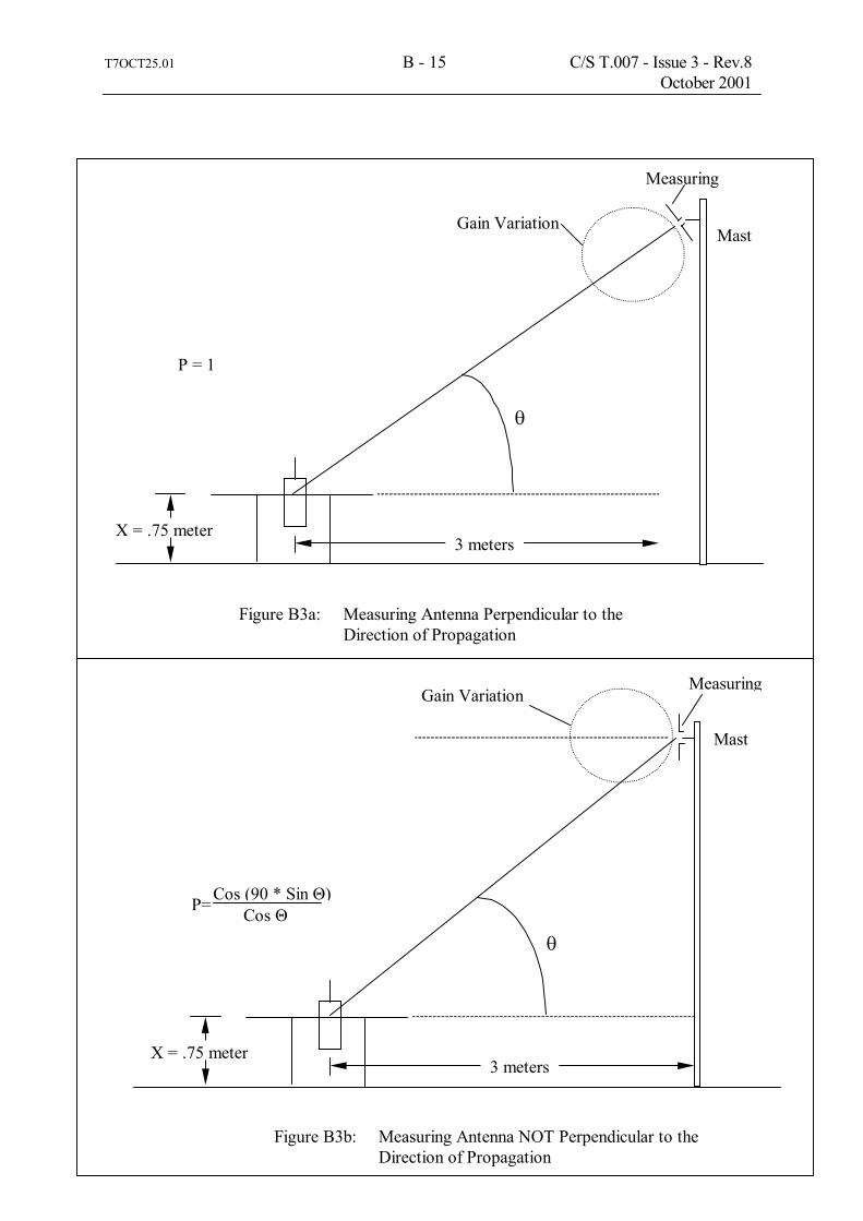
T7OCT25.01 B - 15 C/S T.007 - Issue 3 - Rev.8 October 2001
Figure B3a: Measuring Antenna Perpendicular to the Direction of Propagation
Gain Variation
Measuring
3 meters X = .75 meter
P = 1
Figure B3b: Measuring Antenna NOT Perpendicular to the Direction of Propagation
Gain Variation Measuring
3 meters X = .75 meter
Mast
Mast
Cos Θ Cos (90 * Sin Θ)
θ
θ
P=

Fi
gure
B4:
RF
Mea
sure
men
t Dur
ing
Prea
mbl
e
- EN
D O
F A
NN
EX B
-
REF
10.
0 dB
m
ATTE
N 2
0 dB
CEN
TER
406
.025
00 M
Hz
RES
BW
1 k
Hz
VBW
1 k
Hz
SPAN
50.
00 k
Hz
SWP
300
mse
c
10 d
B/
MKR
406
.025
05 M
Hz
5.70
dBm
T7OCT25.01 B - 16 C/S T.007 � Issue 3 � Rev.8 October 2001

T7OCT03 C - 1 C/S T.007 - Issue 3 - Rev.10 October 2003
ANNEX C
APPLICATION FOR A COSPAS-SARSAT 406 MHz BEACON TYPE APPROVAL CERTIFICATE
Beacon Manufacturer: ____________________________________________________________ Beacon Model: ___________________________________________________________________ Name and Location of Beacon Test Facility: ___________________________________________ Beacon Type: Aviation: _____ Land: _____ Maritime: _____ Specified Operating Temperature Range: °C to °C Specified Operating Lifetime: 24 hr. _____ 48 hr. _____ Other _____ Specify: _____ Beacon Battery Type(s):
Chemistry: _____________________________________________________________
Manufacturer & model no.: ________________________________________________
Size & number of cells: ___________________________________________________
Beacon Oscillator: Type (OCXO, MCXO, TCXO, ....): ___________________________________
Model, Manufacturer: ______________________________________________ Extra Features in Beacon: No Yes Details
a) Auxiliary Radio-Locating Device: _____ _____ Frequency: ____________________ Power: _______________________ Tx. Duty Cycle: ________________
b) Transmits Encoded Position Data: _____ _____ Nav. Device (Internal or External): ____
Type (GPS, GLONASS, etc.): ________ Manufacturer: _________________ Model: _______________________
c) Transmits Long Message (144 bits): _____ _____
d) Automatic Activation: _____ _____
e) Built-in Strobe Light: _____ _____ Intensity: _________________ Flash rate: _________________ f) Self-test mode _____ _____
g) Other: _____ _____ Specify: __________________ I hereby confirm that the 406 MHz beacon described above has been successfully tested in accordance with the Cospas-Sarsat Type Approval Standard (C/S T.007) and complies with the Cospas-Sarsat Specification (C/S T.001) as demonstrated in the attached report. Dated:..................................... Signed:............................................................................. (for test facility) Send to: Cospas-Sarsat Secretariat c/o Inmarsat, 99 City Road, London EC1Y 1AX, United Kingdom

T7OCT03 C - 2 C/S T.007 - Issue 3 - Rev.10 October 2003 406 MHz BEACON SELF-TEST CHARACTERISTICS 406 MHz Beacon Model(s): ____________________________________________________ Answer (√) Yes No 1. Beacon self-test mode
• self-test has a separate switch position .......... │ ......... • does self-test switch automatically return to normal position when released ? .......... │ .........
• self-test transmits a 406 MHz signal .......... │ .........
- normal data, but with inverted frame synchronization pattern .......... │ ......... - 1 burst only .......... │ .........
• does self-test transmit a 121.5 MHz signal ? .......... │ ......... if yes: - for less than 1 second .......... │ ......... - continually while self-test switch is activated .......... │ .........
- other (please specify) : ______________________________ ......... │
• does self-test transmit any other frequency (e.g. 243 MHz) ? ......... │ .........
2. Result of self-test is indicated by: • pass/fail display indicator light .......... │ ......... • strobe light flash .......... │ .........
• other (please specify) : ___________________________________ .......... │
3. Can the self-test be performed without removing the beacon from its mounting bracket ? .......... │ .........
4. What parameters are internally tested by the self-test ? • battery voltage .......... │ ......... • RF power at 406 MHz .......... │ ......... • RF power at 121.5 MHz, if applicable .......... │ ......... • approximate RF frequency .......... │ ......... • phase locked loop .......... │ .........
• other (please specify) : ____________________________________ .......... │
5. Do the above characteristics apply to this beacon model: • for all countries where beacon is sold ? ......... │ .........
if no, please specify : ________________________________________ • for all production serial numbers? ......... │ .........
if no, please specify : _________________________________________
6. Comments: ________________________________________________________________
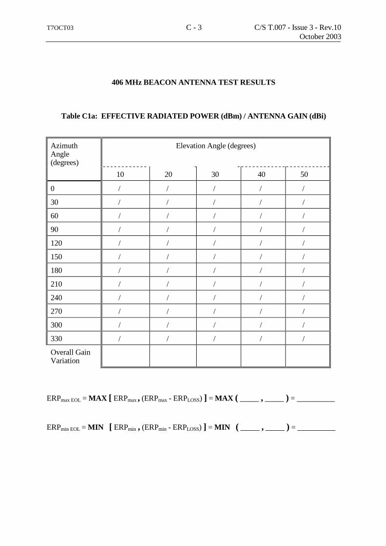
T7OCT03 C - 3 C/S T.007 - Issue 3 - Rev.10 October 2003
406 MHz BEACON ANTENNA TEST RESULTS
Table C1a: EFFECTIVE RADIATED POWER (dBm) / ANTENNA GAIN (dBi)
Azimuth Angle (degrees)
Elevation Angle (degrees)
10 20 30 40 50
0 / / / / /
30 / / / / /
60 / / / / /
90 / / / / /
120 / / / / /
150 / / / / /
180 / / / / /
210 / / / / /
240 / / / / /
270 / / / / /
300 / / / / /
330 / / / / /
Overall Gain Variation
ERPmax EOL = MAX [ ERPmax , (ERPmax - ERPLOSS) ] = MAX ( _____ , _____ ) = __________ ERPmin EOL = MIN [ ERPmin , (ERPmin - ERPLOSS) ] = MIN ( _____ , _____ ) = __________

T7OCT03 C - 4 C/S T.007 - Issue 3 - Rev.10 October 2003
Table C1b: INDUCED VOLTAGE MEASUREMENTS Vv/ Vg (dBuV)
Azimuth Angle (degrees)
Elevation Angle (degrees)
10 20 30 40 50
0 / / / / /
30 / / / / /
60 / / / / /
90 / / / / /
120 / / / / /
150 / / / / /
180 / / / / /
210 / / / / /
240 / / / / /
270 / / / / /
300 / / / / /
330 / / / / /
Min(Vv-Vg)

Table C2: SUMMARY OF 406 MHz BEACON TEST RESULTS
PARAMETERS TO BE MEASURED DURING TESTS RANGE OF SPECIFICATION
UNITS TEST RESULTS COMMENTS
Tmin.
( _____ °C)
Tamb.
( _____ °C)
Tmax.
( _____°C)
1. POWER OUTPUT
• transmitter power output
• power output rise time
• power output 1 ms before burst
35 - 39 < 5 must be < -10 dBm
dBm ms √ *
2. DIGITAL MESSAGE Bits number
• bit sync 1-15 • frame sync 16-24 • format flag 25 • protocol flag 26 • identification/position data 27-85 • BCH code 86-106 • emerg. code/nat. use/supplem. data 107-112 • additional data/BCH (if applicable) 113-144 • position error (if applicable)
15 bits "1" 9 bits (000101111) 1 bit 1 bit 59 bits 21 bits 6 bits 32 bits < 5
√ √ data bit data bit √ √ data bits √ km
T7O
CT30.98D
C/S T
.007 - Issue 3 - Rev.5
October 1998
T7OC
T03 C
- 5 C
/S T.007 - Issue 3 - Rev.10
October 2003

PARAMETERS TO BE MEASURED DURING TESTS
RANGE OF SPECIFICATION
UNITS TEST RESULTS COMMENTS
Tmin.
( _____ °C)
Tamb.
( _____ °C)
Tmax.
( _____°C)
3. DIGITAL MESSAGE GENERATOR
• repetition rate TR
average TR =
minimum TR
maximum TR =
standard deviation • unique TR sequence
probability of 2 beacons with identical patterns (analysis to be provided)
• bit rate:
minimum fb =
maximum fb =
• total transmission time:
short message =
long message =
• unmodulated carrier
minimum T1 =
maximum T1 =
• first burst delay
48.5 - 51.5
47.5
52.5
0.5 - 2.0
< 0.001
396
404
435.6 - 444.4
514.8 - 525.2
158.4
161.6 > 47.5
seconds
seconds
seconds
√
bits/sec.
bits/sec.
ms
ms
ms
ms seconds
T7OC
T03 C
- 6 C
/S T.007 - Issue 3 - Rev.10
October 2003

PARAMETERS TO BE MEASURED DURING TESTS
RANGE OF SPECIFICATION
UNITS TEST RESULTS COMMENTS
Tmin.
( _____ °C)
Tamb.
( _____ °C)
Tmax.
( _____°C)
4. MODULATION • Biphase-L
• rise time
• fall time
• phase deviation: positive
• phase deviation: negative
• symmetry measurement
50 - 250 50 - 250 +(1.0 to 1.2) - (1.0 to 1.2) ≤ 0.05
√ microsec. microsec. radians radians √
5. 406 MHz TRANSMITTED FREQUENCY
• nominal value
• short term stability
• medium term stability:
- slope - residual frequency variation
as specified in C/S T.001 and C/S T.012
≤ 2 x 10 -9 (-1 to +1) x 10 -9 ≤ 3 x 10 -9
MHz /100 ms /minute
6. SPURIOUS EMISSIONS** (into 50 Ohms)
• in-band (406.0 - 406.1 MHz)
see spurious emission mask in C/S T.001
√
T7OC
T03 C
- 7 C
/S T.007 - Issue 3 - Rev.10
October 2003

PARAMETERS TO BE MEASURED DURING TESTS
RANGE OF SPECIFICATION
UNITS TEST RESULTS COMMENTS
Tmin.
( _____ °C)
Tamb.
( _____ °C)
Tmax.
( _____°C)
7. 406 MHz VSWR CHECK after open circuit, short circuit, then while VSWR is 3:1, measure:
• nominal transmitted frequency Modulation:
• rise time
• fall time
• phase deviation: positive
• phase deviation: negative
• symmetry measurement
• digital message
as specified in C/S T.001 and C/S T.012 50 - 250 50 - 250 +(1.0 to 1.2) - (1.0 to 1.2) ≤ 0.05 must be correct
MHz microsec. microsec. radians radians √ √
T7OC
T03 C
- 8 C
/S T.007 - Issue 3 - Rev.10
October 2003

PARAMETERS TO BE MEASURED
DURING TESTS RANGE OF
SPECIFICATION UNITS TEST RESULTS COMMENTS
8. SELF-TEST MODE • frame sync
• format flag
• single radiated burst
• default position data (if applicable)
• description provided
• design data provided on protection
against repetitive self-test mode transmissions
• single burst verification
• provides for beacon 15 Hex ID
9 bits (011010000) 1/0 ≤ 440/520 (+1%) must be correct protection provided one burst must be correct
√ bit ms √ √ √ √ √
9. THERMAL SHOCK** (30°C change)
• Soak temperature:
• Measurement temperature:
the following parameters are to be met within 15 minutes of beacon turn on and maintained for 2 hours:
• transmitted frequency:
• nominal value • short-term stability • medium-term stability:
- slope - residual frequency variation
• transmitter power output
• digital message
as specified in C/S T.001 and C/S T.012
≤ 2 x 10 -9 (-1 to +1) x 10 -9 ≤3 x 10 -9 35 - 39
must be correct
MHz /100 ms /minute dBm
√
Tsoak = _______ °C
Tmeas = _______ °C
T7OC
T03 C
- 9 C
/S T.007 - Issue 3 - Rev.10
October 2003

PARAMETERS TO BE MEASURED DURING TESTS
RANGE OF SPECIFICATION
UNITS TEST RESULTS COMMENTS
10. OPERATING LIFETIME AT MINIMUM TEMPERATURE**
• duration
• transmitted frequency:
• nominal value • short-term stability • medium-term stability:
- slope - residual frequency variation
• transmitter power output
• digital message
> 24
as specified in C/S T.001 and C/S T.012
≤ 2 x 10 -9 (-1 to +1) x 10 -9 ≤ 3 x 10 -9
35 - 39
must be correct
hours
MHz
/100 ms /minute
dBm
√
________ hours at Tmin = ________°C
11. TEMPERATURE GRADIENT** (5°C/hr)
• transmitted frequency:
• nominal value
• short-term stability
• medium-term stability: - slope - residual frequency variation
• transmitter power output
• digital message
as specified in C/S T.001 and C/S T.012
≤ 2 x 10 -9 (-1 to +1) x 10 -9 ≤ 3 x 10 -9
35 - 39
must be correct
MHz /100 ms /minute
dBm
√
T7OC
T03 C
- 10 C
/S T.007 - Issue 3 - Rev.10
October 2003

PARAMETERS TO BE MEASURED DURING TESTS
RANGE OF SPECIFICATION
UNITS TEST RESULTS COMMENTS
12. LONG TERM FREQUENCY STABILITY
• data provided
as specified in C/S T.001 and C/S T.012
MHz
√
13. PROTECTION AGAINST CONTINUOUS TRANSMISSION
• description provided
≤45 seconds
√
14. SATELLITE QUALITATIVE TESTS**
• results provided successfully located by satellites / LUT and position within 5 km
√ √
15. ANTENNA CHARACTERISTICS
• polarization
• VSWR
• ERPmax EOL
• ERPmin EOL
• azimuth gain variation at 40° elevation angle
linear or RHCP ≤1.5
≤ 20
≥ 1.6
≤ 3
√ √ -
Watts
Watts
dB
16. BEACON CODING SOFTWARE
• sample message provided for each coding option of the applicable coding protocol types
• sample self-test message provided for each coding option of the applicable coding protocol types
must be correct
must be correct
√
√
(attach to report)
(attach to report)
T7OC
T03 C
- 11 C
/S T.007 - Issue 3 - Rev.10
October 2003

PARAMETERS TO BE MEASURED DURING TESTS
RANGE OF SPECIFICATION
UNITS TEST RESULTS COMMENTS
17. NAVIGATION SYSTEM** (as applicable)
• position data default values
• position acquisition time
• encoded position data update interval
• position data input update interval (as applicable)
• coarse position close to actual position
• delta offset:
- positive direction
- negative direction
- overrange to 2 times coarse res.
• last valid position:
- retained after navigation input lost
- cleared when beacon reactivated
• design data provided on protection against beacon degradation due to navigation device, interface or signal failure or malfunction
must be correct
< 30 / 1
> 20
20 / 1
must be correct
must be correct
must be correct
must be correct
240 (± 5)
must be correct
no degradation
√
minutes
minutes
minutes
√
√
√
√
min
√
√
18. ADDITIONAL TYPES OF PROTOCOL**
print out of the messages provided, if applicable, with encoded positions at least 5 km apart for each applicable coding protocol type
must be correct
√
(attach to report)
* the tick mark √ can be used where indicated to record that the requirement is met (no value needs to be shown) ** attach graphs of test results for test numbers 6, 9, 10 and 11, and a summary table of results for test numbers 14, 17, and 18
T7OC
T03 C
- 12 C
/S T.007 - Issue 3 - Rev.10
October 2003
- END
OF A
NN
EX C
-

T7OC
T17.02 D
- 1 C
/S T.007 – Issue 3 – Rev.9
October 2002
WHEREAS, The ABC Beacon Company of London, England, the manufacturer of a 406 Megahertz Distress Beacon packaged as an EPIRB, and identified as Model ABC-406 has submitted test data and had said beacon tested in January 2003 at a facility accepted by Cospas-Sarsat at Intespace, Toulouse, France, to demonstrate that said beacon meets the applicable technical requirements for use with the Cospas-Sarsat Satellite System, as defined in documents C/S T.001 “Specification for Cospas-Sarsat 406 MHz Distress Beacons”, Issue 3 – rev. 4, October 2002 and C/S T.007 “Cospas-Sarsat 406 MHz Distress Beacon Type Approval Standard”, Issue 3 – Rev. 9 October 2002,* for the frequency channels 406.0XX MHz and 406.0XY MHz;
WHEREAS, the Cospas-Sarsat Council has determined, following a review of the test results, that the said beacon meets the Cospas-Sarsat Class 2 requirements and is rated for operating over the temperature range of -20°C to +55C**, with battery: XXX Battery Company, type 123 (4 D-cells) (battery chemistry) and
WHEREAS, said manufacturer has certified that all other units of the same type will meet said technical requirements in a similar manner to the unit subjected to test, which incorporated the following features: - 121.5 MHz auxiliary radio locating device (20 dBm, continuous) - Automatic activation mechanism - Strobe light (0.75 cd, 20 flashes/min) - Internal nav. device (GPS): manufacturer: YYY, model: ZZZ - Self-test mode: one burst of 520 ms * beacon is approved for use with user location protocol ** specified operating lifetime 48 hours
NOW, THEREFORE, in reliance upon the following, the Cospas-Sarsat Council does hereby certify that the 406 MHz Distress Beacon Model identified herein is compatible with the Cospas-Sarsat System as of the date of this Certificate.
Certificate No…nnn…………………… Date: 15 February 2003
Signed by: D. Levesque
Head of Cospas-Sarsat Secretariat
NOTE, HOWEVER: 1. This certificate does not authorize the operation or sale of any 406 MHz distress beacon. Such authorization may require type acceptance by national administrations in countries where the beacon will be distributed, and may also be subject to national licensing requirements.
2. This certificate is intended only as a formal notification to the above identified manufacturer that the Cospas-Sarsat Council has determined, on the basis of test data of a beacon submitted by the manufacturer, that 406 MHz distress beacons of the type identified herein meet the standards for use with the Cospas-Sarsat System. This certificate is not a warranty and Cospas-Sarsat hereby expressly disclaims any and all liability arising out of or in connection with the issuance, use, or misuse of this certificate.
3. This certificate is subject to revocation by the Cospas-Sarsat Council should the beacon type for which it is issued cease to meet the Cospas-Sarsat specification. A new certificate may be issued after satisfactory corrective action has been taken and correct performance demonstrated in accordance with the Cospas-Sarsat Type Approval Standard.
COSPAS-SARSAT TYPE APPROVAL CERTIFICATE
For a 406 Megahertz Distress Beacon for use with the Cospas-Sarsat Satellite System

T7OCT17.02 D - 2 C/S T.007 - Issue 3 - Rev.9 October 2002 page left blank

T7OCT25.01 E - 1 C/S T.007 - Issue 3 - Rev.8 October 2001 ANNEX E CHANGE NOTICE FORM The Manufacturer of the Cospas-Sarsat Type Approved 406 MHz Distress Beacons: Manufacturer: __________________________________________________ (name and address) __________________________________________________ __________________________________________________ 406 MHz Beacon Model Numbers: __________________________________________________ Cospas-Sarsat Type Approval Certificate Numbers: __________________________________________ Proposed New Model Numbers of Beacon: _________________________________________________ hereby informs Cospas-Sarsat of the following changes to production beacons planned date of change _______________ Oscillator type: _____ Battery: _____ (specify): ________________________________ Antenna type: _____ Homing transmitter: _____ Strobe light: _____ Size or shape of beacon package: _____ Significant change to circuit design: _____ Internal navigation device: _____ (specify): _________________________________ Other _____ (specify): _________________________________ and substantiates these changes with the attached technical documentation and beacon test results (if applicable). I hereby confirm that with these changes the above 406 MHz beacon models are technically equivalent to the type approved beacon and continue to meet the Cospas-Sarsat requirements. Dated: ........................................ Signed: .......................................................................... (for manufacturer) Complete and send to: Cospas-Sarsat Secretariat, c/o Inmarsat, 99 City Road, London EC1Y 1AX, United Kingdom, Fax: +44 20 7728 1170

T7OCT25.01 E - 2 C/S T.007 - Issue 3 - Rev.8 October 2001
page left blank

T7OCT25.01 F - 1 C/S T.007 - Issue 3 - Rev.8 October 2001
ANNEX F DESIGNATION OF ADDITIONAL NAMES OF A
COSPAS-SARSAT TYPE APPROVED 406 MHz BEACON MODEL The Manufacturer of the following Cospas-Sarsat Type Approved 406 MHz Distress Beacon: Beacon Manufacturer: (name and address) 406 MHz Beacon model: having Cospas-Sarsat Type Approval Certificate Number: hereby informs Cospas-Sarsat that the above beacon will also be sold as: Additional name and model number of beacon: by Agent/Distributor: (name and address) telephone: fax: contact person/title: I certify that we have an agreement with this agent/distributor to market the above-referenced 406 MHz beacon, which we will manufacture and which will be identical to the Cospas-Sarsat type approved beacon, except for labelling. Dated: ..................... Signed: ....................................................................... (for manufacturer) Complete and send to: Cospas-Sarsat Secretariat, c/o Inmarsat, 99 City Road, London EC1Y 1AX, United Kingdom, Fax: +44 20 7728 1170

T7OCT25.01 F - 2 C/S T.007 - Issue 3 - Rev.8 October 2001 - END OF ANNEX F -

T7OCT30.98D G - 1 C/S T.007 - Issue 3 - Rev.5October 1998
ANNEX G
SAMPLE PROCEDURE FOR TYPE APPROVAL TESTING OF 406 MHz BEACONS WITH VOICE TRANSCEIVER
The following sample procedure illustrates the guidelines provided in section C/S T.001,section A3.7.2, concerning the testing of beacons with operator controlled ancillary devices. It is applicable to beacons with operator controlled voice transceivers but may need to beadapted for specific beacon designs. All other aspects of the testing, as documented inC/S T.007 are unchanged.
1. Beacon Voice Transceiver Configuration
The following requirements pertain to the configuration of the beacon voice transceiver for theduration of all testing:
a. if the beacon has a volume control setting, the beacon loudspeaker shall be setto maximum volume;
b. if the beacon includes a manual squelch mode, this shall be selected, and it shallbe set to its most sensitive level;
c. if the beacon includes different transmitter power levels, the highest level shallbe selected; and
d. any other manual settings shall be set to the mode which creates the highestload on the beacon battery.
2. Thermal Shock Test (C/S T.007, section A2.2)
The beacon transceiver shall be operated as described below for the duration of the thermalshock test:
a. 5 Seconds (+/- 2.5 Seconds) before the first beacon burst to be measured, thevoice transmitter shall transmit for 30 seconds, followed immediately by 30seconds during which the beacon voice transmitter is not active. The receivemode shall be activated during the 30 seconds following the transmission cycle. This process shall be repeated for 15 minutes; and
b. thereafter, the transceiver shall be configured to repeat the following cycle, 3times in succession, once each hour;
(i) transmit for 30 seconds,
(ii) followed by 30 seconds receiving.

T7OCT28.99 G - 2 C/S T.007 - Issue 3 - Rev.6 October 1999 3. Operating Lifetime at Minimum Temperature (C/S T.007, section A2.2) The beacon transceiver shall be operated as described below, for the duration of this test:
a. for the first 15 minutes of this test, the transceiver shall be operated as described at paragraph 2.a above;
b. 4 hours before the end of the test period the procedure described at
paragraph 2.a above shall be repeated for 15 minutes; and
c. for the full duration of the test except the periods specified in paragraphs (a) and (b) above, the transceiver shall be operated to drain maximum energy from the battery.
4. Frequency Stability Test with Temperature Gradient (C/S T.007, section A2.4) The beacon transceiver shall be operated as described below, for the duration of this test:
a. the transceiver shall be operated as described at paragraph 2.b above for the duration of the test period; and
b. in addition, the transceiver shall be operated as described at paragraph 2.a
above for one 15 minute period during which the temperature is rising, and for one 15 minute period during which the temperature is falling.
5. Satellite Qualitative Tests (C/S T.007, section A2.5) The beacon transceiver shall be operated as described at paragraph 2.a above for the entire duration that the beacon is in view of the satellite. 6. All Other Tests For all other tests, the beacon transceiver shall be operated as described at paragraph 2.b above. - END OF ANNEX G -
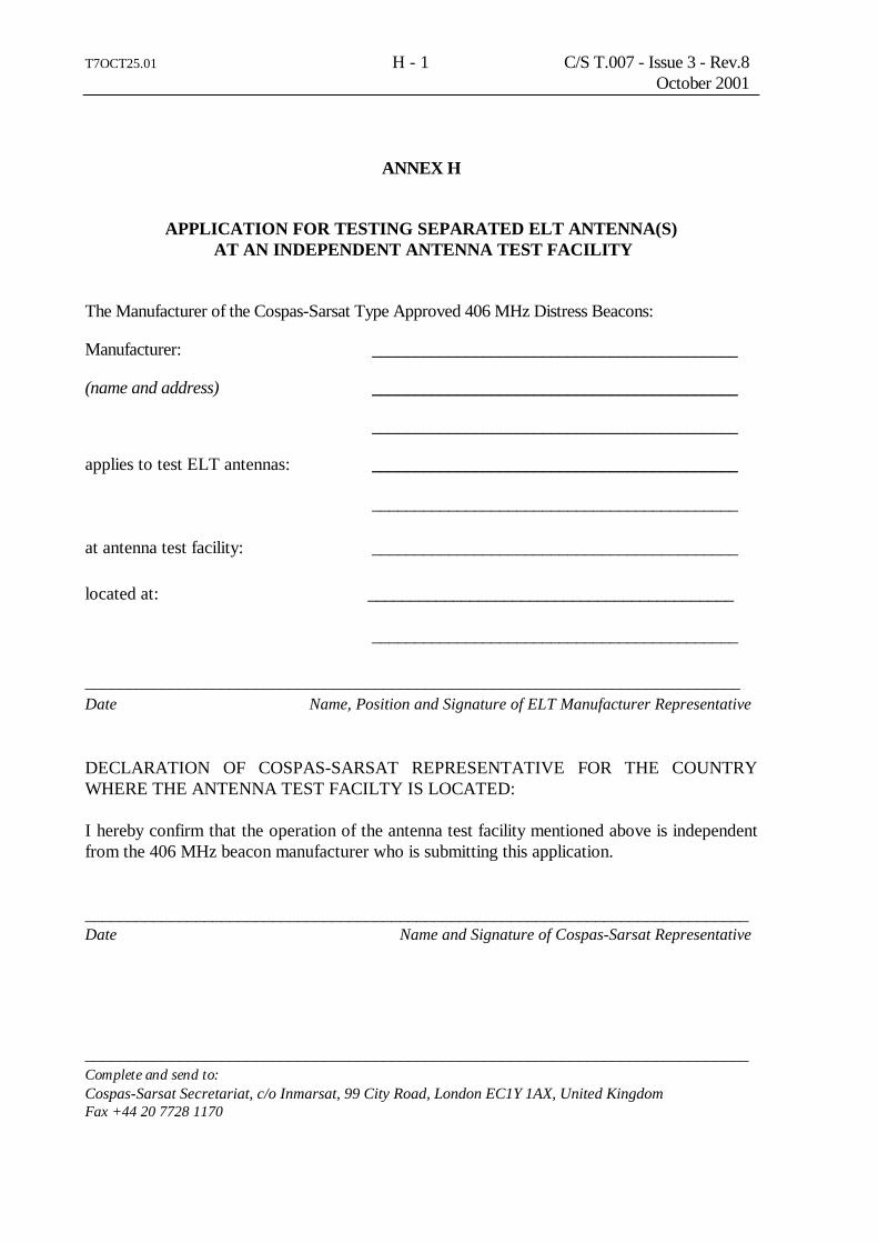
T7OCT25.01 H - 1 C/S T.007 - Issue 3 - Rev.8 October 2001
ANNEX H
APPLICATION FOR TESTING SEPARATED ELT ANTENNA(S) AT AN INDEPENDENT ANTENNA TEST FACILITY
The Manufacturer of the Cospas-Sarsat Type Approved 406 MHz Distress Beacons: Manufacturer: ___________________________________________ (name and address) ___________________________________________ ___________________________________________ applies to test ELT antennas: ___________________________________________ ___________________________________________ at antenna test facility: ___________________________________________ located at: ___________________________________________ ___________________________________________ _____________________________________________________________________________ Date Name, Position and Signature of ELT Manufacturer Representative DECLARATION OF COSPAS-SARSAT REPRESENTATIVE FOR THE COUNTRY WHERE THE ANTENNA TEST FACILTY IS LOCATED: I hereby confirm that the operation of the antenna test facility mentioned above is independent from the 406 MHz beacon manufacturer who is submitting this application. ______________________________________________________________________________ Date Name and Signature of Cospas-Sarsat Representative ______________________________________________________________________________ Complete and send to: Cospas-Sarsat Secretariat, c/o Inmarsat, 99 City Road, London EC1Y 1AX, United Kingdom Fax +44 20 7728 1170

T7OCT25.01 H - 2 C/S T.007 - Issue 3 - Rev.8 October 2001 - END OF ANNEX H -

T7OCT25.01 I - 1 C/S T.007 - Issue 3 – Rev.10 October 2003
ANNEX I
REQUEST TO EXCLUDE ELT ANTENNA(S) FROM THE COSPAS-SARSAT SECRETARIAT
LIST OF ELT ACCEPTED ANTENNAS The Manufacturer of the Cospas-Sarsat 406 MHz ELT: Manufacturer: ___________________________________________ (name and address) ___________________________________________ ___________________________________________ requests that the following ELT antenna(s), designed by us: (model, part number) used with the 406 MHz ELT: ___________________________________________ not be included in the Cospas-Sarsat Secretariat list of accepted ELT antennas Date Name, Position and Signature of ELT Manufacturer Representative Complete and send to: Cospas-Sarsat Secretariat, c/o Inmarsat, 99 City Road, London EC1Y 1AX, United Kingdom Fax +44 20 7728 1170

T7OCT25.01 I - 2 C/S T.007 - Issue 3 – Rev.10 October 2003 - END OF ANNEX I -

T7OCT03 J - 1 C/S T.007 - Issue 3 - Rev.10 October 2003
ANNEX J
BEACON QUALITY ASSURANCE PLAN
We, manufacturer of Cospas-Sarsat 406 MHz beacons (Manufacturer name and address) ___________________________________________ ___________________________________________ confirm that ALL PRODUCTION UNITS of the following beacon model(s), (model, part number) designed by us will be subjected to following tests at ambient temperature: - Digital message - Bit rate - Rise and fall times of the modulation waveform - Modulation Index (positive/negative) - Output power - Frequency stability (short, medium)*
Note*: Beacon manufacturer shall provide technical data on the beacon frequency generation to demonstrate that the frequency stability tests at ambient temperature are sufficient for ensuring that each production beacon will exhibit frequency stability performance similar to the beacon submitted for type approval over the complete operating temperature range. If such assurance of adequate performance over the complete operating temperature range cannot be deduced from the technical data provided and the frequency stability test results at ambient temperature, a thermal gradient test shall be performed on all production units.
- Other tests:
_________________________________________________________________________________________________________________________________________________________________________________________________________________________________________________________________________________________________________________________________________________________
We confirm that the above tests will be performed as appropriate to ensure that the complete beacon satisfies Cospas-Sarsat requirements, as demonstrated by the test unit submitted for type approval. We agree to keep the test result sheet of every production beacon for inspection by Cospas-Sarsat, if required, for a minimum of 10 years. We confirm that Cospas-Sarsat representative(s) have the right to visit our premises to witness the production and testing process of the above-mentioned beacons. We understand that the cost related to the visit is to be borne by Cospas-Sarsat.

T7OCT03 J - 2 C/S T.007 - Issue 3 - Rev.10 October 2003 We also accept that, upon official notification of Cospas-Sarsat, we may be required to re-submit a unit of the above beacon model selected by Cospas-Sarsat for the testing of parameters chosen at Cospas-Sarsat discretion at a Cospas-Sarsat accepted test facility selected by the Cospas-Sarsat. We understand that the cost of the testing shall be borne by Cospas-Sarsat. We understand that the Cospas-Sarsat Type Approval Certificate is subject to revocation should the beacon type for which it was issued, or its modifications, cease to meet the Cospas-Sarsat specifications, or Cospas-Sarsat has determined that this quality assurance plan is not implemented in a satisfactory manner. Date Name, Position and Signature of beacon Manufacturer Representative Complete and send to: Cospas-Sarsat Secretariat, 99 City Road, London EC1Y 1AX, United Kingdom Fax +44 20 7728 1170 - END OF ANNEX J - - END OF DOCUMENT -


.
Cospas-Sarsat SecretariatInmarsat, 99 City Road, London EC1Y 1AX, United Kingdom
Telephone: +44 20-7728 1391 Facsimile +44 20-7728 1170Internet e-mail:[email protected]
Web Site address: http://www.cospas-sarsat.org