CosmoWhite CosmoPolis - Philips · 4 CosmoPolis - CosmoWhite. 2. Luminaire design 2.1. ... overload...
29
CosmoPolis - CosmoWhite Highly efficient - long lasting OEM GUIDE for the use and application of Philips Cosmopolis-MASTER Cosmo White 02-03-2012 11:11:30
Transcript of CosmoWhite CosmoPolis - Philips · 4 CosmoPolis - CosmoWhite. 2. Luminaire design 2.1. ... overload...

CosmoPolis -CosmoWhiteHighly efficient - long lasting
OEM GUIDE for the use and application of Philips Cosmopolis-MASTER Cosmo White 02-03-2012 11:11:30
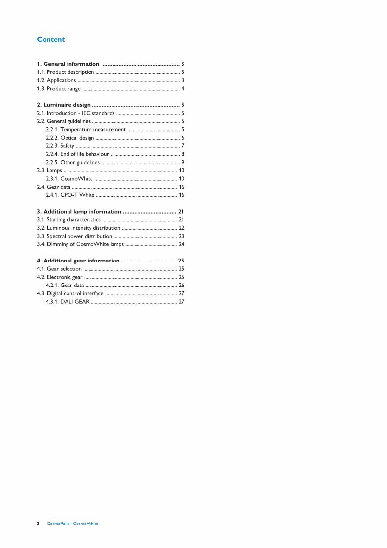
Content
1. General information ................................................ 31.1. Product description ................................................................. 31.2. Applications ............................................................................... 31.3. Product range ............................................................................ 4
2. Luminaire design ....................................................... 52.1. Introduction - IEC standards ................................................. 52.2. General guidelines .................................................................... 5
2.2.1. Temperature measurement ........................................ 52.2.2. Optical design ................................................................. 62.2.3. Safety ................................................................................ 72.2.4. End of life behaviour ..................................................... 82.2.5. Other guidelines ............................................................. 9
2.3. Lamps ........................................................................................ 102.3.1. CosmoWhite ............................................................... 10
2.4. Gear data ................................................................................. 162.4.1. CPO-T White .............................................................. 16
3. Additional lamp information ................................. 213.1. Starting characteristics .......................................................... 213.2. Luminous intensity distribution .......................................... 223.3. Spectral power distribution ................................................. 233.4. Dimming of CosmoWhite lamps ........................................ 24
4. Additional gear information .................................. 254.1. Gear selection ........................................................................ 254.2. Electronic gear ........................................................................ 25
4.2.1. Gear data ....................................................................... 264.3. Digital control interface ....................................................... 27
4.3.1. DALI GEAR .................................................................. 27
2 CosmoPolis - CosmoWhite

1. General information1.1. Product descriptionThe CosmoPolis system consists of:
• New lamp family.
• New electronic driver platform (electronic driven only) tocomplement the system. It is designed to fulfil all requirementsfrom the demanding public lighting application and ensures youa future-proof installation.
• Lumistep - DALI - Primavision.
Product features
• High system efficiencies: up to 120 lm/W for the lamp; up to90% efficiency for the electronic driver.
• Unique burner design and positioning in combination with bestlamp fixation.
• Compact: reduced size to 50% compared to SON/HPLsystems.
• Electronic driver designed for outdoor applications.
Product benefits
• High system energy efficacy: sound TCO.
• Best optical efficacy. This allows greater spacing betweenluminaires (+10%) and thus lower investment.
• Compactness offers optimization in design of optics andluminaires.
• Xtra long lamp service lifetime. Energy saving initially and overlifetime.
• A Green product to minimise environmental impact andCO2 emission.
• Attractive white light.
1.2. ApplicationsCosmoWhite has optimum performance for white light inoutdoor applications. Compared to the existing white lightsources in outdoor lighting (HPL, CDO) the CosmoWhitesystem has superior performance in system efficiency (higherlamp efficacy + driver efficiency + better optical efficiency).Moreover, the lumen maintenance is strongly improvedcompared to existing ceramic or quartz metal halide lamps usedin outdoor. The lamp is very compact: dimensions areoptimised with respect to the optical performance of the lampin the luminaire.
CosmoPolis - CosmoWhite 3
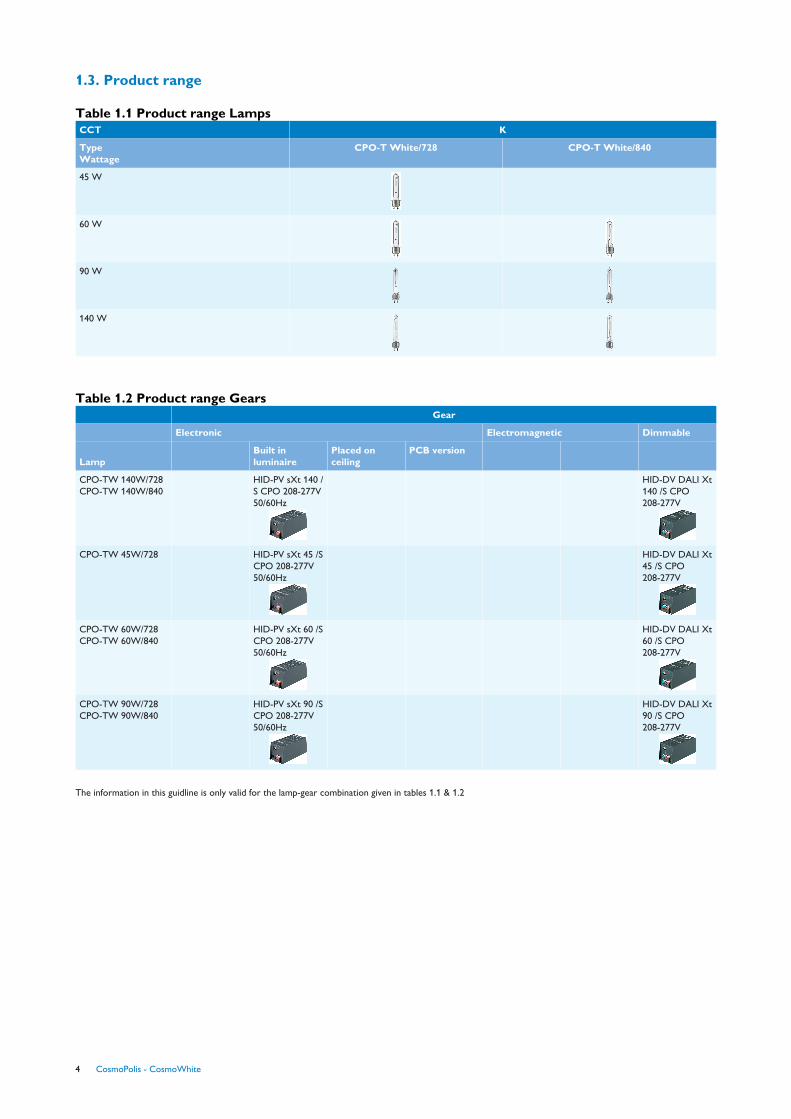
1.3. Product range
Table 1.1 Product range LampsCCT K
Type Wattage
CPO-T White/728 CPO-T White/840
45 W
60 W
90 W
140 W
Table 1.2 Product range Gears
Lamp
Gear
Electronic Electromagnetic Dimmable
Built inluminaire
Placed onceiling
PCB version
CPO-TW 140W/728 CPO-TW 140W/840
HID-PV sXt 140 /S CPO 208-277V50/60Hz
HID-DV DALI Xt140 /S CPO208-277V
CPO-TW 45W/728 HID-PV sXt 45 /SCPO 208-277V50/60Hz
HID-DV DALI Xt45 /S CPO208-277V
CPO-TW 60W/728 CPO-TW 60W/840
HID-PV sXt 60 /SCPO 208-277V50/60Hz
HID-DV DALI Xt60 /S CPO208-277V
CPO-TW 90W/728 CPO-TW 90W/840
HID-PV sXt 90 /SCPO 208-277V50/60Hz
HID-DV DALI Xt90 /S CPO208-277V
The information in this guidline is only valid for the lamp-gear combination given in tables 1.1 & 1.2
4 CosmoPolis - CosmoWhite

2. Luminaire design2.1. Introduction - IEC standardsThe CosmoPolis system is designed to offer optimal lightdistribution, energy saving and miniaturisation. Lamp and gearshould be used according to the following IEC norms.
Table 2.1 Related IEC standards.Item IEC/CISPR Description
Radio Disturbance CISPR15 Interference relating tolighting equipment
Lamp 61167 Metal Halide lamps
Luminaire 60598 Luminaires
Cap and holder 60838-1 PGZ12
2.2. General guidelines
2.2.1. Temperature measurement
2.2.1.1. Lamp Temperature
IntroductionThe temperatures of the bulb and the pinch are most critical.The temperature of the bulb is important for the operatingtemperatures inside the lamp (arc tube temperature). If thistemperature is too high, the lamp properties and especially thelifetime properties can be altered. The critical point is justabove the light centre, at the upper side of the lamp, when thelamp burns horizontally.
Measurement setupAll lamps and measurement connections must be electricallyinsulated to withstand the maximum ignition pulses of typically2.2kV for the Xtreme drivers. The lamps have to be operatedon the appropriate Philips driver and in the PGZ12 lamp holder. Lamps should be stabilised at least ten minutes prior to themeasurement. No sleeves have to be used around the lampsfor the measurements.
The bulb temperature should be measured in horizontalburning position, with the lead wire downwards and thethermocouple at the upper side of the bulb, because this is themost critical situation. The maximal allowed temperatures aregiven in the next sections at Table 2.4. Critical points.
To measure the temperature of the pinch, the thermocoupleshould be fixed on the pinch at the spot where the joint isbetween the outer lead and the molybdenum foil. Thistemperature is most critical in the base-up burning position. Since this point is not accessible any more when the lamp baseis mounted on the lamp, related temperatures are given justbelow the lamp base. These are given in the Table 2.4 Criticalpoints.
ThermocouplesFor the measurements as referred to in this document, NiCrthermocouples are used. Lamps with thermocouplesconnected can be ordered in Turnhout via the Philips salesorganisation. The fixation of the thermocouples on the lamp isdone by engraving a small depression in the outer bulb. Thejunction point of the thermocouple is located in thisdepression. For a better fixation of the thermocouple, the twowires are twisted at the opposite side of the lamp and are fixedat the sides with a high temperature cement or a springmechanism.
Figure 2.1 Thermocouple connected to bulb and pinch.
CosmoPolis - CosmoWhite 5

2.2.1.2. Gear Temperature
IntroductionThe temperature of the electronics is an most importantparameter for lifetime and reliability of the gear. In the designeverything possible is done to keep the componenttemperature as low as possible, but the design of the luminaireand the ability to guide the heat out of the luminaire is of highimportance.
Definitions• Gear temperature: temperature measured on the Tc point of
the gear. Temperature Tc mentioned on the label is thetemperature point where the lifetime and all otherspecifications are guaranteed.
• Gear ambient temperature: temperature inside the luminairearound the gear.
• Luminaire ambient temperature: temperature outside theluminaire (see Figure 2.1).
Figure 2.2 Temperature definitions
Measurement setupTo enable temperature measurements in a luminaire withoutmeasuring the individual components in the electronic gear aT-case point has been defined. This point, or the indicationwhere this point is located can be found on the label of theelectronic gear. In the definition of the T-case point ahomogeneous temperature around the gear is assumed. Forthat reason, it is better to design the luminaire based on geartemperatures rather than gear ambient temperatures.Therefore, the T-case temperature limits mentioned on thegear label and in chapter 2.4 (Gear Data) are leading overambient temperature values mentioned on the gear label.
Please refer to chapter 4 to (Additional Gear information) forthe effect of the temperature on the gear lifetime.
2.2.2. Optical designThe surface finishing of the reflection material to be used forthe CosmoPolis lamps should be faceted, patterned or mat.These surfaces will mix the light from the arc to a morehomogeneous beam. Arc colour differences exist due to thedifferent molecular weights of the metals and deposits of themetals in the bottom of the burner that will be projected in thebeam, so the reflector needs to mix the light well. The volumeof the optical system is also important. If this volume is toosmall, both lamp and driver will run too hot and will experienceshort life. Critical temperatures as specified in section 2.3.1.2in table 2.4 should be taken into account to guarantee the lifespecifications for lamp and gear.
2.2.2.1. Reflection
AdviceReflection surfaces parallel to the lamp are not allowed, as theywill reflect the heat of the lamp back to the parts inside thelamp. The critical parts are: the whole burner and the ‘getter’disk (the square metal object with the grey round metaldeposit). When this disk is thermally overloaded, the areaaround the disk will very soon get blackened. The burner issensitive to any extra heat load at both ends. This mightoverload the seals, causing a crack in the ceramic or leaky glassseal, leading to shorter life of the lamp.
Measurement setupFirst measure the lamp temperatures as explained in thebeginning of this chapter. However, this gives onlytemperatures on the outer bulb, not inside the lamp. As anextra check on the optical system, a cool-down curve of thelamp temperature can be made in the following way: Thetemperature after switch off of the lamp should be recordedfor about 20 seconds. In some cases a strong discontinuity inthis curve after 1 to 3 seconds after switch-off can be found.This might be an indication of extreme heating of thethermocouple and hence the lamp surface by reflection fromthe optical system, which should be avoided. For HID-lamps,often a comparative measurement of the lamp voltage insideand outside the luminaire is used to check whether the burneris not too hot. As the lamp is surrounded by a narrow reflectorand/or housing, a lamp voltage rise can occur. However, forlamps operated on an electronic gear such as Cosmopolislamps, the lamp power is stabilized by the gear such that thelamp voltage remains practically unchanged.
6 CosmoPolis - CosmoWhite
2.2.3. Safety
Containment safetyAs for CDM-lamps, the chance for non-passive failure of theCosmoWhite burners at end-of-life (by e.g. wrong driverchoice or short circuit situation) cannot be excluded. When theburner shatters, this can lead to cracks of even shattering of theouter bulb. Therefore, we prescribe that CosmoWhite lampsmust be operated in fully enclosed luminaires, able to containall the broken hot parts of the lamp. However, it must be notedthat the occurrence of non-passive failures is very unlikely.
Temperature safetyFor CosmoWhite lamps, it has been found that the lamp voltagedoes not increase significantly, as long as the reflector/housingis not too small. As such, for CosmoWhite lamps the lampvoltage is not a good measure to assess whether a luminaire iscritical with respect to lamp temperature or not. Even if therewould be a minimal lamp voltage rise, the lamp power does stayconstant (consequence of the use of an electronic gear).Therefore, light technical properties like luminous flux, colourrendering, and colour coordinates remain practicallyunchanged in a luminaire.
The lamp-luminaire combination must be tested in the mostunfavourable situation in order to measure if certain points ofthe lamp (or luminaire) do not exceed the given limittemperatures.
Electrical safetyAll CosmoWhite lamps have to be operated in fully closedluminaires.
For optimal lightning protection of the system make sure thereis sufficient distance between parts in the luminaire connectedto the lamp output on the driver and parts connected to theground connection of the gear.
Make sure that the wiring inside the luminaire is as much aspossible in line with the description in this guide.
Photo biological safetyThe standards on photo biological safety (I.E.C.62471/ ANSI/IESNA RP-27.3-96) aim to prevent potential injury from lightsources, by prescribing adequate cautions and warnings.Potential injuries in scope are skin burn and damage to eyeretina or eye lens.
The standards contain a risk group classification-ranging fromexempted to risk group 4-regarding these optical radiationhazards in the wavelength range from 200nm through 3000nm.For every risk group, adequate cautions and warning areprescribed with whom lamps must be labeled.
CosmoWhite lamps are classified in risk group 1 for blue lighthazard. No warning information is necessary
CosmoPolis - CosmoWhite 7
2.2.4. End of life behaviourThe reasons why a CosmoWhite lamp can stop functioningafter its specified lifetime are similar to the mechanisms forCDM-lamps:
• Due to chemical reactions between the arc tube filling and thePCA of the tube, the tube will become leaky. The hot gases willflow through this leak into the outer bulb, noticeable as a weakdischarge in the outer bulb. In principle, it cannot be excludedthat the PCA will break and hot PCA parts may cause a ruptureof the outer bulb (“non-passive failure”). However,containment safety testing has not shown any non-passivefailures with CosmoWhite lamps.
• If the arc tube becomes leaky, the lamp stops functioning.However, in some cases the lamp continues burning for a fewhundred hours with a strongly deviating colour before iteventually stops completely. Conversely, when a lamp operateswith strongly deviating colour, this might be an indication of thearc tube being leaky.
• The lamp voltage can rise too much to be sustained by theballast. This voltage rise can be caused by a change in thechemical composition during lifetime or by electrodes wearingout. In case of a too high lamp voltage, the lamp extinguishes.
An overload situation, e.g. a 60W lamp operating on a 140Wsystem, will speed up the occurrence of the above-mentionedfailure mechanisms.
• When the arc tube becomes leaky and the fill gas flows intothe outer bulb, a glow discharge will appear around the metalparts in the outer bulb. In the arc tube itself no discharge ispresent anymore. The glow discharge is NOT detrimental forany part of the system. Additionally, the glow effects are limitedin time by a timing function in the electronic driver that switchesoff the circuit after 20 minutes in case of a leaky lamp. When the lamp voltage reaches a too high value, the ballast willswitch off the system. This way, disturbing cycling effects (lampsswitching on and off continuously) are prevented. We advise toreplace end-of-life lamps whenever possible.
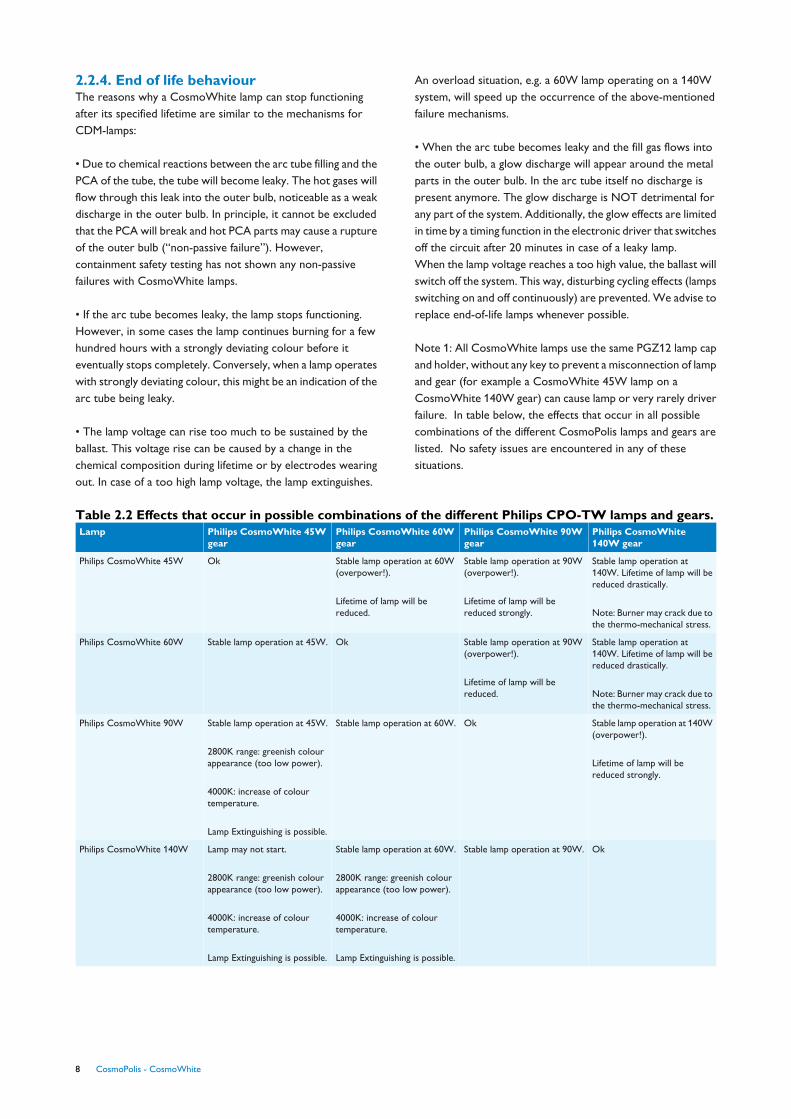
Note 1: All CosmoWhite lamps use the same PGZ12 lamp capand holder, without any key to prevent a misconnection of lampand gear (for example a CosmoWhite 45W lamp on aCosmoWhite 140W gear) can cause lamp or very rarely driverfailure. In table below, the effects that occur in all possiblecombinations of the different CosmoPolis lamps and gears arelisted. No safety issues are encountered in any of thesesituations.
Table 2.2 Effects that occur in possible combinations of the different Philips CPO-TW lamps and gears.Lamp Philips CosmoWhite 45W
gearPhilips CosmoWhite 60Wgear
Philips CosmoWhite 90Wgear
Philips CosmoWhite140W gear
Philips CosmoWhite 45W Ok Stable lamp operation at 60W(overpower!).
Lifetime of lamp will bereduced.
Stable lamp operation at 90W(overpower!).
Lifetime of lamp will bereduced strongly.
Stable lamp operation at140W. Lifetime of lamp will bereduced drastically.
Note: Burner may crack due tothe thermo-mechanical stress.
Philips CosmoWhite 60W Stable lamp operation at 45W. Ok Stable lamp operation at 90W(overpower!).
Lifetime of lamp will bereduced.
Stable lamp operation at140W. Lifetime of lamp will bereduced drastically.
Note: Burner may crack due tothe thermo-mechanical stress.
Philips CosmoWhite 90W Stable lamp operation at 45W.
2800K range: greenish colourappearance (too low power).
4000K: increase of colourtemperature.
Lamp Extinguishing is possible.
Stable lamp operation at 60W. Ok Stable lamp operation at 140W(overpower!).
Lifetime of lamp will bereduced strongly.
Philips CosmoWhite 140W Lamp may not start.
2800K range: greenish colourappearance (too low power).
4000K: increase of colourtemperature.
Lamp Extinguishing is possible.
Stable lamp operation at 60W.
2800K range: greenish colourappearance (too low power).
4000K: increase of colourtemperature.
Lamp Extinguishing is possible.
Stable lamp operation at 90W. Ok
8 CosmoPolis - CosmoWhite

2.2.5. Other guidelines
Lamp handling
Fingerprints on metal halide lamps in a quartz outerbulb (including Philips CosmoPolis lamps).
When low wattage quartz metal halide lamps were introducedit was stated that the lamp should be cleaned with alcohol if itwas touched by bare fingers. This was based on the story thatfor halogen lamps, where the quartz wall temperature is muchhigher during the burning of the lamps: the grease and acids ofthe fingerprints are burning into the quartz at thesetemperatures. This has an influence on the light distribution ofthe lamp and can result in a possible short life as the quartz isweakened. However, the maximum temperature of the outer-bulb of metal halide lamps in quartz bulb is much lower (e.g.Max. < 550ºC for a 140W CosmoWhite lamp). In life tests itappeared that after a few hundred hours all fingerprints weregone. For this reason, the phrase in the instructions for use(‘wipe-off the lamp with alcohol in case of fingerprints’) wasremoved from the instructions for use for CDM andCosmoPolis lamps.
CosmoPolis - CosmoWhite 9

2.3. Lamps
2.3.1. CosmoWhite
2.3.1.1. Information
1 The CosmoWhite lamps can be operated in all positions, butwith different properties. The lamp is optimized forhorizontal burning. When rotating the lamp from thehorizontal towards the vertical burning position, the colourtemperature will drop around 150K for 2800K range and upto 250K for 4000K range compared to the horizontaldata. The colour rendering (Ra8) will drop with ~5 points. Also lifetime properties will decrease. In the table below,the specifications of the lamp are given if operated in bothhorizontal and vertical burning position.
2 Definition S/P ratio: The eye sensitivity depends on theamount of light. This means, a human eye is more sensitiveto blue light at low light levels. The S/P ratio contains therelation between the photopic (daylight) and scotopic(complete darkness) flux. To calculate the mesopic flux(twilight), the photopic flux has to be multiplied with the S/P ratio. S/P ration of Cosmo 2800K range is around 1.2,while for the 4000K range it is around 1.6. For reference,the S/P ratio for standard HPS lamps is around 0.5.
3 Product information requirements on lamps as in the E.U.P.regulation 245/2009 formulated.
• Rated Lamp Lumen Maintenance factor: as a factor orexpressed in % - LLMF
• Rated Lamp Survival factor: as a factor or expressed in % -LSF
10 CosmoPolis - CosmoWhite

Unit CPO-TW 45W/728
CPO-TW 60W/728
CPO-TW 90W/728
CPO-TW 140W/728
Product Dimensions
Overall Length-C max. mm 132 132 143 149.8
Diameter-D max. mm 20 20 20 20
Light Center Length-L nom. mm 59 59 66 66
Arc Length-O nom. mm 14 14 18 22
Electrical Characteristics
Lamp Wattage Rated EL 25 degree C. W 45 60 90 140
Lamp Current EL nom. A 0.484 0.644 0.97 1.49
Lamp Wattage EL at +/- 60% power W 30 36 54 84
Lamp Current EL at +/- 60% power mA 0.309 0.383 0.577 0.931
Lamp Voltage nom. V 91 92 92 94
Ignition Peak Voltage max. (Pulse) V 5000 5000 5000 5000
General Characteristics
Burning position any any any any
10% Survival rate, horizontal hr 22000 22000 20000 16000
50% Survival rate, horizontal hr 30000 30000 30000 30000
10% Survival rate, base up hr 13000 13000 13000 16000
50% Survival rate, base up hr 16000 16000 16000 30000
LSF EL 2kh Rated,12h cyc. horizontal % 99 99 99 99
LSF EL 4kh Rated,12h cyc. horizontal % 99 99 99 99
LSF EL 6kh Rated,12h cyc. horizontal % 99 99 99 99
LSF EL 8kh Rated,12h cyc. horizontal % 99 99 99 98
LSF EL 12kh Rated,12h cyc. horizontal % 99 99 98 95
LSF EL 16kh Rated,12h cyc. horizontal % 98 98 96 90
LSF EL 20kh Rated,12h cyc. horizontal % 95 95 90 81
LSF EL 24kh Rated,12h cyc. horizontal % 87 87 75 N.A.
LSF EL 30kh Rated,12h cyc. horizontal % 50 50 50 N.A.
LSF EL 2kh Rated,12h cyc. base up % 99 99 99 N.A.
LSF EL 4kh Rated,12h cyc. base up % 99 99 99 N.A.
LSF EL 6kh Rated,12h cyc. base up % 99 99 99 N.A.
LSF EL 8kh Rated,12h cyc. base up % 99 99 99 N.A.
LSF EL 12kh Rated,12h cyc. base up % 92 92 92 N.A.
LSF EL 16kh Rated,12h cyc. base up % 50 50 50 N.A.
Light Technical Characteristics
Color Temp. Technical, horizontal nom. K 2725 2760 2750 2860
Color Temp. Technical, base up nom. K 2630 2590 2640 2860
Colour Temp. at +/-60% power horiz. K 2815 2715 2675 2880
Color Rendering Index, horizontal nom. Ra8 66 73 66 66
Color Rendering Index, base up nom. Ra8 60 67 58 66
Chromaticity Coordinate X nom. 459 453 454 444
Chromaticity Coordinate Y nom. 412 405 406 401
Chrom. Coord. X at +/- 60% power horiz. 459 461 463 449
Chrom. Coord. Y at +/- 60% power horiz. 424 414 414 414
Lum. Flux EL25 degree C. Rated. horiz. Lm 4950 7200 10450 16500
Lum. Flux EL25 degree C, Rat. base up Lm 4455 6780 10000 16500
Luminous Flux at +/- 60% power horiz. Lm 2520 3240 4752 7560
Lum Effic Rat 25 degree C. horizontal Lm/W 110 120 116 118
Lum Effic Rat EL 25 degree C. base up Lm/W 99 113 111 118
Luminous Efficacy at +/- 60% power Lm/W 84 90 88 90
LLMF EL 2 kh Rated, horizontal % 92 92 94 97
LLMF EL 4 kh Rated, horizontal % 90 90 91 97
CosmoPolis - CosmoWhite 11
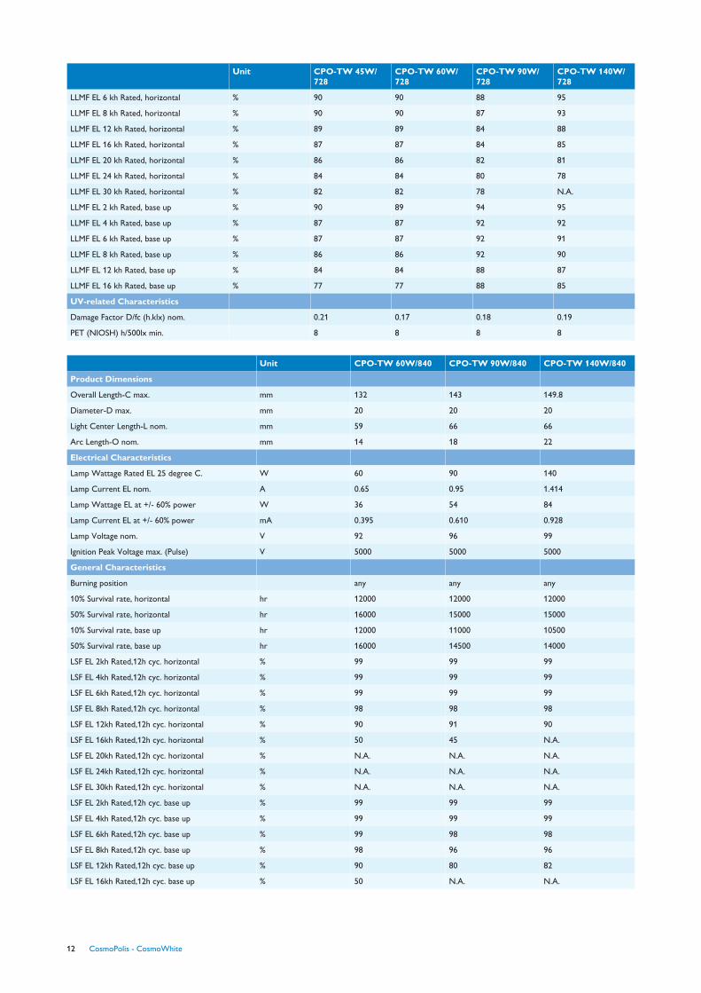
Unit CPO-TW 45W/728
CPO-TW 60W/728
CPO-TW 90W/728
CPO-TW 140W/728
LLMF EL 6 kh Rated, horizontal % 90 90 88 95
LLMF EL 8 kh Rated, horizontal % 90 90 87 93
LLMF EL 12 kh Rated, horizontal % 89 89 84 88
LLMF EL 16 kh Rated, horizontal % 87 87 84 85
LLMF EL 20 kh Rated, horizontal % 86 86 82 81
LLMF EL 24 kh Rated, horizontal % 84 84 80 78
LLMF EL 30 kh Rated, horizontal % 82 82 78 N.A.
LLMF EL 2 kh Rated, base up % 90 89 94 95
LLMF EL 4 kh Rated, base up % 87 87 92 92
LLMF EL 6 kh Rated, base up % 87 87 92 91
LLMF EL 8 kh Rated, base up % 86 86 92 90
LLMF EL 12 kh Rated, base up % 84 84 88 87
LLMF EL 16 kh Rated, base up % 77 77 88 85
UV-related Characteristics
Damage Factor D/fc (h.klx) nom. 0.21 0.17 0.18 0.19
PET (NIOSH) h/500lx min. 8 8 8 8
Unit CPO-TW 60W/840 CPO-TW 90W/840 CPO-TW 140W/840
Product Dimensions
Overall Length-C max. mm 132 143 149.8
Diameter-D max. mm 20 20 20
Light Center Length-L nom. mm 59 66 66
Arc Length-O nom. mm 14 18 22
Electrical Characteristics
Lamp Wattage Rated EL 25 degree C. W 60 90 140
Lamp Current EL nom. A 0.65 0.95 1.414
Lamp Wattage EL at +/- 60% power W 36 54 84
Lamp Current EL at +/- 60% power mA 0.395 0.610 0.928
Lamp Voltage nom. V 92 96 99
Ignition Peak Voltage max. (Pulse) V 5000 5000 5000
General Characteristics
Burning position any any any
10% Survival rate, horizontal hr 12000 12000 12000
50% Survival rate, horizontal hr 16000 15000 15000
10% Survival rate, base up hr 12000 11000 10500
50% Survival rate, base up hr 16000 14500 14000
LSF EL 2kh Rated,12h cyc. horizontal % 99 99 99
LSF EL 4kh Rated,12h cyc. horizontal % 99 99 99
LSF EL 6kh Rated,12h cyc. horizontal % 99 99 99
LSF EL 8kh Rated,12h cyc. horizontal % 98 98 98
LSF EL 12kh Rated,12h cyc. horizontal % 90 91 90
LSF EL 16kh Rated,12h cyc. horizontal % 50 45 N.A.
LSF EL 20kh Rated,12h cyc. horizontal % N.A. N.A. N.A.
LSF EL 24kh Rated,12h cyc. horizontal % N.A. N.A. N.A.
LSF EL 30kh Rated,12h cyc. horizontal % N.A. N.A. N.A.
LSF EL 2kh Rated,12h cyc. base up % 99 99 99
LSF EL 4kh Rated,12h cyc. base up % 99 99 99
LSF EL 6kh Rated,12h cyc. base up % 99 98 98
LSF EL 8kh Rated,12h cyc. base up % 98 96 96
LSF EL 12kh Rated,12h cyc. base up % 90 80 82
LSF EL 16kh Rated,12h cyc. base up % 50 N.A. N.A.
12 CosmoPolis - CosmoWhite
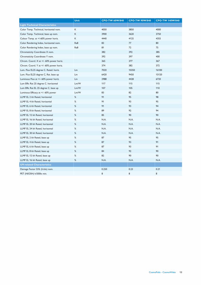
Unit CPO-TW 60W/840 CPO-TW 90W/840 CPO-TW 140W/840
Light Technical Characteristics
Color Temp. Technical, horizontal nom. K 4050 3850 4000
Color Temp. Technical, base up nom. K 3900 3620 3750
Colour Temp. at +/-60% power horiz. K 4440 4125 4355
Color Rendering Index, horizontal nom. Ra8 83 77 80
Color Rendering Index, base up nom. Ra8 81 72 75
Chromaticity Coordinate X nom. 382 392 385
Chromaticity Coordinate Y nom. 392 397 400
Chrom. Coord. X at +/- 60% power horiz. 365 377 367
Chrom. Coord. Y at +/- 60% power horiz. 374 382 372
Lum. Flux EL25 degree C. Rated. horiz. Lm 7020 10350 16100
Lum. Flux EL25 degree C, Rat. base up Lm 6420 9450 15120
Luminous Flux at +/- 60% power horiz. Lm 2988 4428 6720
Lum Effic Rat 25 degree C. horizontal Lm/W 117 115 115
Lum Effic Rat EL 25 degree C. base up Lm/W 107 105 110
Luminous Efficacy at +/- 60% power Lm/W 83 82 80
LLMF EL 2 kh Rated, horizontal % 91 95 98
LLMF EL 4 kh Rated, horizontal % 91 93 95
LLMF EL 6 kh Rated, horizontal % 91 93 94
LLMF EL 8 kh Rated, horizontal % 89 92 94
LLMF EL 12 kh Rated, horizontal % 85 90 90
LLMF EL 16 kh Rated, horizontal % N.A. N.A. N.A.
LLMF EL 20 kh Rated, horizontal % N.A. N.A. N.A.
LLMF EL 24 kh Rated, horizontal % N.A. N.A. N.A.
LLMF EL 30 kh Rated, horizontal % N.A. N.A. N.A.
LLMF EL 2 kh Rated, base up % 87 95 95
LLMF EL 4 kh Rated, base up % 87 93 91
LLMF EL 6 kh Rated, base up % 87 93 91
LLMF EL 8 kh Rated, base up % 84 92 90
LLMF EL 12 kh Rated, base up % 82 90 90
LLMF EL 16 kh Rated, base up % N.A. N.A. N.A.
UV-related Characteristics
Damage Factor D/fc (h.klx) nom. 0.250 0.23 0.21
PET (NIOSH) h/500lx min. 8 8 8
CosmoPolis - CosmoWhite 13

2.3.1.2. Critical pointsThe temperature of the bulb and the pinch are most critical,and must be kept below the values in the following table.
Table 2.4 Critical pointsFigure Max. temperature for Philips CosmoWhite
45W/728Philips CosmoWhite60W/728 -60W/840
Philips CosmoWhite90W/728 -90W/840
Philips CosmoWhite140W/728 -140W/840
Figure 2.2
bulb at position rightabove the center of thearc tube (most critical
horizontal)
380°C 400°C 470°C 550°C
Figure 2.3
pinch (most critical base-up)
250°C 300°C 300°C 300°C
2.3.1.3. Lamp base and holderThe following table gives some specific elements with regardsto the lamp base and holder.
Table 2.5 Lamp base and holder.Element Explanation
Type holder PGZ12 lamp base and holder.
Figure 2.4 lamp base and holder.
Orientation in luminaire The lamps can always be mounted in the same position in the optics (i.e. with the long frame wire at the bottom if burning horizontally).
The holder is equipped with a special feature to define its orientation in the luminaire.
Positioning The PGZ12 is a “pre-focused” lamp base, which means that the burner is aligned with the reference plane of the cap before fixing thebulb in the cap.
Additionally, the specific fit of the cap in the holder (reference plane of cap is pulled against upper rim of holder) guarantees minimaltolerance of the position of the lamp with respect to the reflector. Both these elements allow a better positioning of the arc tube inthe reflector and hence lead to a more reliable and reproducible light output/distribution compared to other lamp base/holder typessuch as E-caps or G12 caps.This ensures an optimized optimal efficiency in road/street lighting optics as described before.
Fixation The twist and lock concept guarantees an optimal fixation of the lamp in the luminaire, also in high vibration applications.
14 CosmoPolis - CosmoWhite

Note 1 : The lamp base is polarised, wich means it has pinswith different diameters (see Fig. 2.4 in Table 2.5) such that itcan be inserted in the lamp holder in one unique way. Thisimplies that:
• For the HID-PV CPO TW gears, the ignition pulse is alwaysapplied on the short pole of the lamp. The symbol on the lampholder and gear contacts indicates how to connect the wiresproperly.
• The lamp output of the Xtreme gear is not polarity sensitivein respect to the lamp. The ignition pulse has a symmetricalcharacter.
Further, this polarisation assurs on good orientation in theluminaire as indicated in Table 2.5.
Note 2 : All CosmoWhite lamps use the same PGZ12 lampcap and holder, without any key to prevent a misconnection oflamp and gear (for example a CosmoWhite 45W lamp on aCosmoWhite 140W gear) can cause lamp or very rarely gearfailure. In Table 4.1 at the section Additional gear information,the effects that occur in all possible combinations of thedifferent Cosmopolis lamps and gears are listed. No safetyissues are encountered in any of these situations.
Note 3: Lamps should be held by the quartz bulb, not by themetal lamp base, while inserting the lamp.
CosmoPolis - CosmoWhite 15

2.4. Gear data
2.4.1. CPO-T White
2.4.1.1. InformationThis chapter gives information about the gears used in CPO-TWhite lamp family. Example -IPVCPOXt 60/140/90/45
Unit HID-PrimaVision Xtreme60 /S CPO-TW220-240V50/60Hz
HID-PrimaVision Xtreme45 /S CPO-TW220-240V50/60Hz
HID-PrimaVision Xtreme140 /SCPO-TW220-240V50/60Hz
HID-PrimaVision Xtreme90 /S CPO-TW220-240V50/60Hz
HID-PVsXt 45 /SCPO208-277V50/60Hz
HID-PVsXt 60 /SCPO208-277V50/60Hz
HID-PVsXt 90 /SCPO208-277V50/60Hz
HID-PVsXt 140 /SCPO208-277V50/60Hz
DV LS sXt60 CPO /0-6-60%
ProductDimensions
Length A1nom
mm 135.0 135.0 150.0 150.0 150.0 150.0 150.0 150.0 150.0
Fixing HoleDistanceLength A2nom
mm 125.7 125.7 135.9 135.9 135.9 135.9 135.9 135.9 135.9
Width B1nom
mm 65.0 65.0 65.0 65.0 65.0 65.0 65.0 65.0 65.0
Fixing HoleDistanceWidth B2nom
mm 46.8 46.8 46.8 46.8 46.8 46.8 46.8 46.8 46.8
Height C1nom
mm 65.0 65.0 65.0 65.0 65.0 65.0 65.0 65.0 65.0
Fixing HoleDiameterD1 nom
mm 4.8 4.8 5.0 5.0 5.0 5.0 5.0 5.0 5.0
GeneralCharacteristics
Line Voltage V 220-240 220-240 220-240 220-240 208-277 208-277 208-277 208-277 208-277
LineFrequency
Hz 50/60 50/60 50/60 50/60 50/60 50/60 50/60 50/60 50/60
RatedBallast-LampWattage
60 45 140 90 45 60 90 140 60
Life time(max.10%failures)
hr 80000 80000 80000 80000 80000 80000 80000 80000 80000
OperatingCharacteristics
PowerFactor 100%outputpower nom
0.95 0.95 0.95 0.95 0.95 0.95 0.95 0.95 0.95
IgnitionVoltage max.
kV 2.9 2.9 2.9 2.9 3.3 3.3 3.3 3.3 3.3
Inrushcurrent Peakmax.
A 29 29 55 55 29 29 56 56 28
InrushcurrentWidth nom
ms 0.50 0.50 0.45 0.45 0.50 0.50 0.50 0.50 0.42
Earthleakagecurrent max
mA 0.7 0.7 0.7 0.7 0.7 0.7 0.7 0.7 0.7
Maximumballastnumber onMCB nom
x 11 11 5 5 11 11 5 5 11
16 CosmoPolis - CosmoWhite

Unit HID-PrimaVision Xtreme60 /S CPO-TW220-240V50/60Hz
HID-PrimaVision Xtreme45 /S CPO-TW220-240V50/60Hz
HID-PrimaVision Xtreme140 /SCPO-TW220-240V50/60Hz
HID-PrimaVision Xtreme90 /S CPO-TW220-240V50/60Hz
HID-PVsXt 45 /SCPO208-277V50/60Hz
HID-PVsXt 60 /SCPO208-277V50/60Hz
HID-PVsXt 90 /SCPO208-277V50/60Hz
HID-PVsXt 140 /SCPO208-277V50/60Hz
DV LS sXt60 CPO /0-6-60%
SystemChar's ondriver level
Power Loss(W)
7.0 6.0 12.5 9.0 N.A. N.A. N.A. N.A. N.A.
TemperatureCharacteristics
T-ambientmax.
C 50 50 50 50 50 50 50 50 50
T-ambientmin.
C -20 -20 -20 -20 -30 -30 -30 -30 -30
T-case lifenom.
C 80 80 80 80 80 80 80 80 80
WiringCharacteristics
Cable-Capoutputwiresmutual nom.
pF 1000 1000 1000 1000 1000 1000 1000 1000 1000
Max. cablelengthDevice/Lamp
m 15 15 15 15 2 2 2 2 2
Unit DV LS sXt60 CPO /2-6-60%
DV LS sXt90 CPO /0-6-60%
DV LS sXt90 CPO /2-6-60%
DV LS sXt140 CPO /0-6-60%
DV LS sXt140 CPO /2-6-60%
HID-DVLS-6 Xt60 /S CPO-TW220-240V
HID-DVLS-8 Xt60 /S CPO-TW220-240V
HID-DVLS-10 Xt60 /S CPO-TW220-240V
HID-DVDALI Xt45 /S CPO208-277V
ProductDimensions
Length A1nom
mm 150.0 150.0 150.0 150.0 150.0 135.0 135.0 135.0 150.0
Fixing HoleDistanceLength A2nom
mm 135.9 135.9 135.9 135.9 135.9 125.7 125.7 125.7 135.9
Width B1nom
mm 65.0 65.0 65.0 65.0 65.0 65.0 65.0 65.0 65.0
Fixing HoleDistanceWidth B2nom
mm 46.8 46.8 46.8 46.8 46.8 46.8 46.8 46.8 46.8
Height C1nom
mm 65.0 65.0 65.0 65.0 65.0 65.0 65.0 65.0 65.0
Fixing HoleDiameterD1 nom
mm 5.0 5.0 5.0 5.0 5.0 4.8 4.8 4.8 5.0
GeneralCharacteristics
Line Voltage V 208-277 208-277 208-277 208-277 208-277 220-240 220-240 220-240 208-277
LineFrequency
Hz 50/60 50/60 50/60 50/60 50/60 50/60 50/60 50/60 50/60
RatedBallast-LampWattage
60 90 90 140 140 60 60 60 45
Life time(max.10%failures)
hr 80000 80000 80000 80000 80000 80000 80000 80000 80000
CosmoPolis - CosmoWhite 17

Unit DV LS sXt60 CPO /2-6-60%
DV LS sXt90 CPO /0-6-60%
DV LS sXt90 CPO /2-6-60%
DV LS sXt140 CPO /0-6-60%
DV LS sXt140 CPO /2-6-60%
HID-DVLS-6 Xt60 /S CPO-TW220-240V
HID-DVLS-8 Xt60 /S CPO-TW220-240V
HID-DVLS-10 Xt60 /S CPO-TW220-240V
HID-DVDALI Xt45 /S CPO208-277V
OperatingCharacteristics
PowerFactor 100%outputpower nom
0.95 0.95 0.95 0.95 0.95 0.95 0.95 0.95 0.95
IgnitionVoltage max.
kV 3.3 3.3 3.3 3.3 3.3 2.9 2.9 2.9 3.3
Inrushcurrent Peakmax.
A 28 52 52 52 52 29 29 29 28
InrushcurrentWidth nom
ms 0.42 0.47 0.47 0.47 0.47 0.5 0.5 0.5 0.42
Earthleakagecurrent max
mA 0.7 0.7 0.7 0.7 0.7 0.7 0.7 0.7 0.7
Maximumballastnumber onMCB nom
x 11 5 5 5 5 11 11 11 11
SystemChar's ondriver level
Power Loss(W)
N.A. N.A. N.A. N.A. N.A. 7.0 7.0 7.0 N.A.
TemperatureCharacteristics
T-ambientmax.
C 50 50 50 50 50 50 50 50 50
T-ambientmin.
C -30 -30 -30 -30 -30 -20 -20 -20 -30
T-case lifenom.
C 80 80 80 80 80 80 80 80 80
WiringCharacteristics
Cable-Capoutputwiresmutual nom.
pF 1000 1000 1000 1000 1000 1000 1000 1000 1000
Max. cablelengthDevice/Lamp
m 2 2 2 2 2 N.A. N.A. N.A. 10
Unit HID-DVLS-6 Xt140 /SCPO-TW220-240V
HID-DVLS-8 Xt140 /SCPO-TW220-240V
HID-DVLS-10 Xt140 /SCPO-TW220-240V
HID-DVLS-6 Xt90 /S CPO-TW220-240V
HID-DVLS-8 Xt90 /S CPO-TW220-240V
HID-DVLS-10 Xt90 /S CPO-TW220-240V
HID-DVDALI Xt60 /S CPO208-277V
HID-DVDALI Xt140 /SCPO208-277V
HID-DVDALI Xt90 /S CPO208-277V
ProductDimensions
Length A1nom
mm 150.0 150.0 150.0 150.0 150.0 150.0 150.0 150.0 150.0
Fixing HoleDistanceLength A2nom
mm 140.7 140.7 140.7 140.7 140.7 140.7 135.9 135.9 135.9
Width B1nom
mm 65.0 65.0 65.0 65.0 65.0 65.0 65.0 65.0 65.0
18 CosmoPolis - CosmoWhite
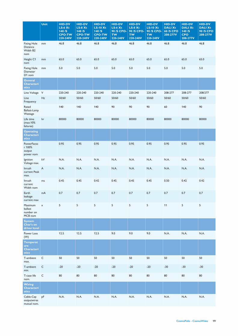
Unit HID-DVLS-6 Xt140 /SCPO-TW220-240V
HID-DVLS-8 Xt140 /SCPO-TW220-240V
HID-DVLS-10 Xt140 /SCPO-TW220-240V
HID-DVLS-6 Xt90 /S CPO-TW220-240V
HID-DVLS-8 Xt90 /S CPO-TW220-240V
HID-DVLS-10 Xt90 /S CPO-TW220-240V
HID-DVDALI Xt60 /S CPO208-277V
HID-DVDALI Xt140 /SCPO208-277V
HID-DVDALI Xt90 /S CPO208-277V
Fixing HoleDistanceWidth B2nom
mm 46.8 46.8 46.8 46.8 46.8 46.8 46.8 46.8 46.8
Height C1nom
mm 65.0 65.0 65.0 65.0 65.0 65.0 65.0 65.0 65.0
Fixing HoleDiameterD1 nom
mm 5.0 5.0 5.0 5.0 5.0 5.0 5.0 5.0 5.0
GeneralCharacteristics
Line Voltage V 220-240 220-240 220-240 220-240 220-240 220-240 208-277 208-277 208/277
LineFrequency
Hz 50/60 50/60 50/60 50/60 50/60 50/60 50/60 50/60 50/60
RatedBallast-LampWattage
140 140 140 90 90 90 60 140 90
Life time(max.10%failures)
hr 80000 80000 80000 80000 80000 80000 80000 80000 80000
OperatingCharacteristics
PowerFactor 100%outputpower nom
0.95 0.95 0.95 0.95 0.95 0.95 0.95 0.95 0.95
IgnitionVoltage max.
kV N.A. N.A. N.A. N.A. N.A. N.A. N.A. N.A. N.A.
Inrushcurrent Peakmax.
A N.A. N.A. N.A. N.A. N.A. N.A. N.A. N.A. N.A.
InrushcurrentWidth nom
ms 0.45 0.45 0.42 0.45 0.45 0.45 0.50 0.42 0.42
Earthleakagecurrent max
mA 0.7 0.7 0.7 0.7 0.7 0.7 0.7 0.7 0.7
Maximumballastnumber onMCB nom
x 5 5 5 5 5 5 11 5 5
SystemChar's ondriver level
Power Loss(W)
12.5 12.5 12.5 9.0 9.0 9.0 N.A. N.A. N.A.
TemperatureCharacteristics
T-ambientmax.
C 50 50 50 50 50 50 50 50 50
T-ambientmin.
C -20 -20 -20 -20 -20 -20 -30 -30 -30
T-case lifenom.
C 80 80 80 80 80 80 80 80 80
WiringCharacteristics
Cable-Capoutputwiresmutual nom.
pF N.A. N.A. N.A. N.A. N.A. N.A. N.A. N.A. N.A.
CosmoPolis - CosmoWhite 19

Unit HID-DVLS-6 Xt140 /SCPO-TW220-240V
HID-DVLS-8 Xt140 /SCPO-TW220-240V
HID-DVLS-10 Xt140 /SCPO-TW220-240V
HID-DVLS-6 Xt90 /S CPO-TW220-240V
HID-DVLS-8 Xt90 /S CPO-TW220-240V
HID-DVLS-10 Xt90 /S CPO-TW220-240V
HID-DVDALI Xt60 /S CPO208-277V
HID-DVDALI Xt140 /SCPO208-277V
HID-DVDALI Xt90 /S CPO208-277V
Max. cablelengthDevice/Lamp
m N.A. N.A. N.A. N.A. N.A. N.A. 10 10 10
2.4.1.2. Circuitry
20 CosmoPolis - CosmoWhite

3. Additional lamp information3.1. Starting characteristicsA resonant ignition voltage of typically 2.2 kVp is used by theCosmoWhite gear to ignite the CosmoWhite lamp. Pulses areapplied to the lamp with a certain on/off sequence (burst mode)with a total duration of maximum 20 minutes (to allow warmrestart of the lamp, and at the same time prevent problems withan end of life lamp). The gears are suitable for 24h/7 daysoperation. As for all discharge lamps, the resistance of the gasin the discharge tube is related to the gas pressure of the
different elements in the tube. Immediately after ignition thelamp voltage is lower and the current is higher. After about 1.5to 2 minutes the gas pressure has been built up and nominallamp performance is reached. This is visualized in the run upcurves figures 3.1 till 3.4.
CosmoWhite lamps do not re-ignite instantly. Warm re-ignition time is specified to be less than 15 minutes.
Run-up curve CPO-TW 45W
Figure 3.1
Run-up curve CPO-TW 60W
Figure 3.2
Run-up curve CPO-TW 90W
Figure 3.3
Run-up curve CPO-TW 140W
Figure 3.4
CosmoPolis - CosmoWhite 21
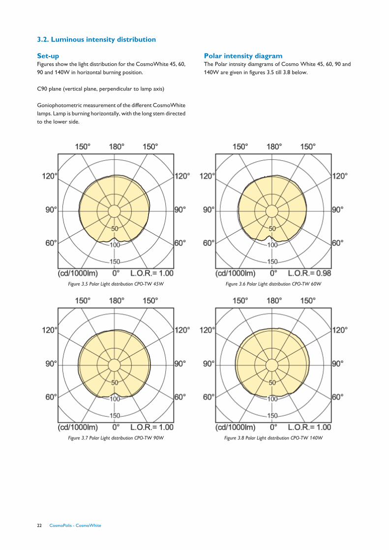
3.2. Luminous intensity distribution
Set-upFigures show the light distribution for the CosmoWhite 45, 60,90 and 140W in horizontal burning position.
C90 plane (vertical plane, perpendicular to lamp axis)
Goniophotometric measurement of the different CosmoWhitelamps. Lamp is burning horizontally, with the long stem directedto the lower side.
Polar intensity diagramThe Polar intnsity diamgrams of Cosmo White 45, 60, 90 and140W are given in figures 3.5 till 3.8 below.
Figure 3.5 Polar Light distribution CPO-TW 45W Figure 3.6 Polar Light distribution CPO-TW 60W
Figure 3.7 Polar Light distribution CPO-TW 90W Figure 3.8 Polar Light distribution CPO-TW 140W
22 CosmoPolis - CosmoWhite

3.3. Spectral power distributionThe spectral power distributions of CosmoWhite 45, 60, 90and 140W are given in figures 3.9 till 3.15 below.
Figure 3.9 Spectral power distribution CPO-TW 45W/728
Figure 3.10 Spectral power distribution CPO-TW 60W/728 Figure 3.11 Spectral power distribution CPO-TW 60W/840
Figure 3.12 Spectral power distribution CPO-TW 90W/728 Figure 3.13 Spectral power distribution CPO-TW 90W/840
Figure 3.14 Spectral power distribution CPO-TW 140W/728 Figure 3.15 Spectral power distribution CPO-TW 140W/840
CosmoPolis - CosmoWhite 23

3.4. Dimming of CosmoWhite lampsCosmoWhite lamps can be dimmed on its CosmoWhiteXtreme gear with LumiStep technology or DALI application.
The lifetime and maintenance of the lamps do not change if thelamps are dimmed on these gears.
The lamps are dimmable to 60% of the lamp power. Thiscorresponds with a light level slightly less than 50% of the fullpower light level. The CosmoWhite 45W lamp is dimmable to30W.
The nominal performance of the lamp at full and dimmed poweris given in the lamp specifications at chapter 2.3.1.1. Thesevalues are obtained with 100h seasoned CosmoWhite lampson a nominal CosmoWhite LumiStep gear.
24 CosmoPolis - CosmoWhite

4. Additional gear information4.1. Gear selection
Remote lamp operation
Remote operation is a name for all applications in outdoorlighting where the gear is not incorporated in the luminaire.
Two technical aspects are determining whether a remoteapplication is possible or not. First of all the ignition voltagepeak is influenced by the cable properties. This means the peakvoltage is flattened by the cable capacity. Depending on theinsulation material some part of the ignition energy can even beabsorbed by the cable. In general the cable capacity is leading.The CosmoPolis Xtreme driver is capable of driving a cablecapacity up to 1000 pF. For an average cable type with a capacityof 100 pF/m this means remote lamp operation with 10 metersof lamp cable are feasible.
On the other hand the system has to be compliant with the EMIregulations. The assembly of the luminaire, the lamp cabling, thepole and the driver are influencing the EMI behaviour. In generalthe closer the two lamp conductors are placed together thelower the EMI radiation. So it is advised to use a cable insteadof two separate wires. A second point of attention is the staycapacity of the lamp conductors to the environment.Composite or wooden poles have the advantage of a lowspreading capacity. Aluminium or steel poles are picking upmore noise from the lamp cables. This disturbance has to beredirected to the driver by a short connection of the metal poleto the functional earth terminal on the driver. However if thelevel of disturbance picked up by the pole is too high, theapplication will not be compliant with the EMI regulations. Forthe same reason screened lamp cables are dissuaded.
Conclusion: Remote operation can be possible but is notadvised. EMI of the complete system has always to be checked.
4.2. Electronic gear
Indoor versus outdoor
Table 4.1 Indoor Products Outdoor Products
(Xtreme)
IP luminaireclassification
Advised luminaireclassification > IP 54
Advised luminaireclassification > IP 23
Air contaminations Not protected Protected
EMC-V_surge EN61547
2kV L/N - Ground
1kV L-N
EN61547
4kV L/N - Ground(Xtreme 10kV)
2kV L-N
Vibrations IEC-600-68-2-6-Fc
Frequency range 10-150Hz.
Acceleration/amplitude2G/0.15 mm peak
IEC-600-68-2-29 Eb
Frequency range 10-150Hz.
Acceleration/amplitude5G/0.15 mm peak
Lifetime 50.000 hours with 10%failures
80.000 hours with 10%failures
Mains voltage(operating)
220-240V -6%..+6% 220-240V -10%..+10%(Xtreme)
Mains voltage (safety) 220-240V -10%..+10% 220-240V -20%..+12%(Xtreme)
EMC CISPR 15 ed 7.1 CISPR 15 ed 7.1
Temperatures 0 to 50°C -30 to 50°C
Classification Class 1 Class 1 and 2
LifetimeThe temperature of the electronics is an important parameterfor lifetime and reliability of the system. In the design everythingpossible is done to keep the component temperature as low aspossible but the design of the luminaire and the ability to guidethe heat out of the luminaire is of utmost importance.
To enable temperature measurements in a luminaire withoutmeasuring the individual components in the electronic gear aTc point has been defined. This point, or the indication wherethis point is located can be found on the label of the electronicgear.
The Tc point specification of the CosmoPolis Xtreme gear hasa lower temperature value than the Tc point spec of the formerrange of electronic outdoor products. This is related to the factthat the Xtreme gear has less power losses and that the Tcpoint is at a different location in the Xtreme products. Thesetwo points together ensure a longer lifetime.
The temperatures as stated above are only valid for a situationwhere the gear is only cooled via the bottom surface. Ifadditional cooling measures are used please contact your Philipsrepresentative for advice.
Example:
If in the application the Tc point is 80ºC (=Tc at which thelifetime spec. of 80.000 hours with 90% survivors is reached forCosmoWhite (s)Xtreme gear) any point in the yellow part mustbe 80°C or lower and any point in the red part must be 75°Cor lower to archieve the specified lifetime at Tc=80°C.
CosmoPolis - CosmoWhite 25

Tc temperature and value on the (s)Xtreme gear
Tc is specified at 80°C on the lable of the CosmoPolis Xtremegears. At this temperature the lifetime of 80.000 hours with90% survivors is reached. At 90°C the thermal protection willswitch off the gear. The gear will start trying to reignite the lampas the gear has cooled down to 80°C.
Operating or even storing the gear at temperatures above 80°C will shorten the lifetime of the product, so we strongly advisetake all the measures to avoid this possibility. When operatingthe gear at temperatures well below 80°C the lifetimeexpectancy of the product can slightly increase with a few10.000 hours with the same failure rate.
Figure 4.1Thermal guard
If the gear temperature exceeds the maximum Tcase, 92±2°C,the thermal protection mechanism will start to dim the lamppower. For the COSMOPOLIS, the lamp power will be reducedto 60% (50% light) and for SON, it will be reduced to 35% (20%light). The gear will be switched off immediately when Tcasereaches 95±2°C. If the temperature drops below Tcase 92±2°C within 25 minutes, the gear will return to full light level.
If the Tcase falls below 80±2°C, the gear will return to theprevious value. Ignition is possible from -30ºC upwards. At verylow temperatures it may take slightly longer to ignite the lamp.
Table 4.2
CPO 45W _ 30W 60W _ 36WSON 50W _ 30W 45W _ 30W
CDO50W _ 37.5W (75%)
« 70% light»
45W _ 30W
« 70% light»
Advise to obtain maximum lifetime:
• Ensure good thermal contact between gear and coldest spotof luminaire. The CosmoPolis (s)Xtreme gear is designed tocomply with all requirements for Class1 and Class2applications hence direct contact with the metal parts of theluminaire are allowed.
• The CosmoPolis Xtreme gear has heat producingcomponents both in the upper and lower part of the gear.Therefore cooling via the bottom only may not give theoptimal result. For optimal result it is advised to also cool the
sides of the gear, including the upper part of the sides. Beaware that for proper verification of gear temperature in thiscase a gear with thermocouples supplied by Philips is neededask your Philips representative for advice.
• Shield the heat of the lamp and reflector.The best is a two-chamber solution, or special measures to transport heat viaair flow away from the gear.
NB: The Tc temperature limits mentioned here andon the gear label are leading over maximum AMBIENTtemperature values mentioned on the gear label!
Ignition is possible from -30ºC upwards. At very lowtemperatures it can take a bit more time to ignite the lamp.
Housing
Figure 4.2 Wiring diagram gear .
4.2.1. Gear data
Lifetime80000 hours with 10% failures
VibrationsFrequency range 10-150Hz
Acceleration/amplitude
5G/0.15mm peak
HousingClass 2 material : Plastic
Installing cabling/EMCCare should be taken when connecting the electronic gear. Besure not to reverse lamp wiring and mains wiring. Avoid shortcircuit of the lamp circuit to ground during operation. Bothfailures will damage the product permanently. Warning:Performing a combined (simultaneous) functional test andinsulation test of the gear with reversed lamps and mains cablingcan cause a severe risk.
Other information
26 CosmoPolis - CosmoWhite

4.3. Digital control interface
4.3.1. DALI GEARDALI Hardware
The signals on the DALI control lines are single pole. This meansthat the DALI control voltage is polarity sensitive. Theconnection of the DALI control lines to the interface terminalsis marked with “DA” for data, because the input is madepolarity insensitive (see Fig. 4.3).
Fig. 4.3 Mains protection and polarityinsensivity Dali gear
Fig. 4.4 Bi-phase encoding
Because the DALI terminals are close to the mains terminals,caution must be exercised when the installation is beingconnected. To prevent damage caused by interchanging theDALI control lines, lamp wires and the mains wires, the DALIsystem is equipped with extra hardware in the interface thatcan withstand the mains voltage (see Fig. 4.3). Because a numberof gears, connected to different mains phases, can be connectedto each other by means of the DALI input, all DALI inputs arefully isolated from the power electronics inside the gear.
This isolation is done in the gear by means of an optical isolator(opto-coupler). The gear backward channel switch, which iscontrolled by the intelligent module (microcontroller) of theballast, shorts the DALI control lines. The short circuit currentof the DALI control lines, which is generated by the DALImaster or power supply, is therefore limited. The current islimited to 250 mA as played down in the DALI standard. Themaximum voltage drop is limited to 2 volt for the DALI line. ADALI bus can be fed at any point on the bus including the endor middle. Any number of branches may be used as long as anyone of them does not exceed 300 meter.
Digital control
The electronic gears are connected to the controller via twowires. Data packets consisting of 19 bits enable the controllerto communicate with the electronic ballasts at an effective rateof 1200 bauds per second. A message is built up by 1 start bit,8 address bits, 8 data bits and 2 stop bits (see figs. 4.5 and 4.6).
Fig. 4.5 Dali message frame Fig. 4.6 Tolerances of DALI line voltage
The DALI line has a voltage of 16 V, with the tolerances shownin Fig. 4.6. The DALI standard requires that the voltage dropbetween the power supply and any DALI device be no morethan 2 volts.
The current in a DALI controller is limited to a maximum of250 mA in accordance with IEC 60929. The currentconsumption per electronic ballast is set at 2 mA. The busconnected load should not exceed 80% of this rating in orderto provide sufficient charging current.
Example: Given 50 gears at 2mA each, a 250mA power supply,and 6mA per control, 16 controls may be used on the bus inaddition to the gears. (250* 80% — 50*20%)/6 = 16 controls/bus
CosmoPolis - CosmoWhite 27
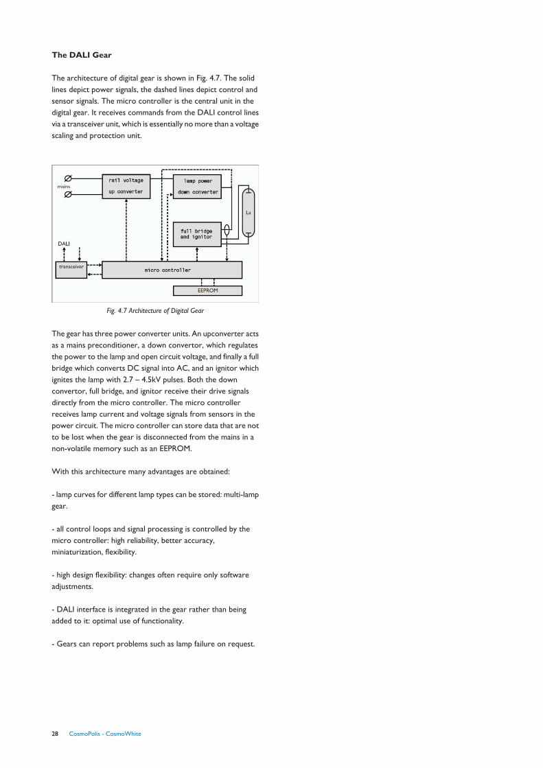
The DALI Gear
The architecture of digital gear is shown in Fig. 4.7. The solidlines depict power signals, the dashed lines depict control andsensor signals. The micro controller is the central unit in thedigital gear. It receives commands from the DALI control linesvia a transceiver unit, which is essentially no more than a voltagescaling and protection unit.
Fig. 4.7 Architecture of Digital Gear
The gear has three power converter units. An upconverter actsas a mains preconditioner, a down convertor, which regulatesthe power to the lamp and open circuit voltage, and finally a fullbridge which converts DC signal into AC, and an ignitor whichignites the lamp with 2.7 – 4.5kV pulses. Both the downconvertor, full bridge, and ignitor receive their drive signalsdirectly from the micro controller. The micro controllerreceives lamp current and voltage signals from sensors in thepower circuit. The micro controller can store data that are notto be lost when the gear is disconnected from the mains in anon-volatile memory such as an EEPROM.
With this architecture many advantages are obtained:
- lamp curves for different lamp types can be stored: multi-lampgear.
- all control loops and signal processing is controlled by themicro controller: high reliability, better accuracy,miniaturization, flexibility.
- high design flexibility: changes often require only softwareadjustments.
- DALI interface is integrated in the gear rather than beingadded to it: optimal use of functionality.
- Gears can report problems such as lamp failure on request.
28 CosmoPolis - CosmoWhite

All rights are reserved. Reproduction in whole or in part is prohibited without prior written consent of the copyright owner. The information presented in thisdocument does not form part of any quotation or contract, is believed to be accurate and reliable and may be changed without notice. No liability will be acceptedby the publisher for any consequence of its use. Publication thereof does not convey nor imply any license under patent-or other industrial or intellectual propertyrights.
The luminaire manufacturer remains responsible for the quality and performance of the total system in the market. He needs to assure that all components in theluminaire are used within specified boundaries, with special attention to, but not limited to, potential safety issues and negative interactions between components ina specified environment.
This OEM guide describes only some recommendations for an optimal functioning of lamp and gear in the luminaire. As Philips has not the control over the design,manufacturing and application of the luminaire, Philips shall not be held liable for the functioning of the system, meaning lamp and gear in the total luminaire solution.Due to continuous improvements and innovations, specifications may change without notice.
CosmoPolis - CosmoWhite 29