CORSICA 2013 work report: Test set generation, FPGA · PDF fileset generation, FPGA model...
49
RESEARCH REPORT VTT-R-00212-14 CORSICA 2013 work report: Test set generation, FPGA model checking, and fault injection Authors: Jussi Lahtinen, Jukka Ranta, Lauri Lötjönen Confidentiality: Public
Transcript of CORSICA 2013 work report: Test set generation, FPGA · PDF fileset generation, FPGA model...
RESEARCH REPORT VTT-R-00212-14
CORSICA 2013 work report: Testset generation, FPGA modelchecking, and fault injectionAuthors: Jussi Lahtinen, Jukka Ranta, Lauri Lötjönen
Confidentiality: Public

RESEARCH REPORT VTT-R-00212-141 (47)
Report’s title
CORSICA 2013 work report: Test set generation, FPGA model checking, and fault injectionCustomer, contact person, address Order reference
VYR3/2013SAF
Project name Project number/Short name
Coverage and rationality of the software I&C safety assurance 77376 CORSICAAuthor(s) Pages
Jussi Lahtinen, Jukka Ranta, Lauri Lötjönen 48/Keywords Report identification code
test set generation, test coverage, FPGA, model checking,fault injection
VTT-R-00212-14
Summary
The CORSICA research project aims to improve the safety evaluation of I&C software innuclear industry by spreading knowledge about software process assessment and rationalityof integrated evaluation methods. Results related to three separate topics of the CORSICAproject are presented in this paper: 1) test set generation for function-block based systems, 2)model checking of FPGA designs, and 3) fault injection in the context of FPGAs.
One of the generic objectives of the CORSICA project is to improve the coverage andrationality of evaluation methods. In this work we have developed a structural testingtechnique for generating test sets for function-block based designs automatically. A proof ofconcept tool has also been implemented.
In 2013, CORSICA also focused on field programmable gate array (FPGA) technology sinceit has become relevant for implementing safety systems in nuclear power plants. In thispaper, our experiences on using the outputs of various FPGA design phases for modelchecking are described. In addition, a technique called fault injection is briefly discussed inthe context of FPGAs.
Confidentiality PublicEspoo, 19.2.2014Written by
Jussi LahtinenResearch Scientist
Reviewed by
Antti PakonenResearch Scientist
Accepted by
Riikka VirkkunenHead of Research Area
VTT’s contact addressVTT Technical Research Centre of FinlandP.O. Box 1000, FI-02044 VTT, FinlandPhone internat. +358 20 722 4520Fax +358 20 722 4374Distribution (customer and VTT)SAFIR2014 Reference group 2
The use of the name of the VTT Technical Research Centre of Finland (VTT) in advertising or publication in part ofthis report is only permissible with written authorisation from the VTT Technical Research Centre of Finland.

RESEARCH REPORT VTT-R-00212-142 (47)
Preface
This report has been prepared under the research project “Coverage and rationalityof the software I&C safety assurance” (CORSICA), which is part of the FinnishResearch Programme on Nuclear Power Plant Safety 2011–2014 (SAFIR2014). Theresearch project aims to improve the safety evaluation of I&C systems in nuclearindustry by spreading knowledge about process assessment and rationality ofintegrated evaluation methods. This paper presents CORSICA results from theproject year 2013. Three separate topics are presented: 1) test set generation forfunction-block based systems, 2) model checking of FPGA designs, and 3) faultinjection in the context of FPGAs.
We wish to express our gratitude to the representatives of the organizations involvedand all those who have given their valuable input in the meetings and discussionsduring the project.
Espoo, February 2014
Authors

RESEARCH REPORT VTT-R-00212-143 (47)
Contents
Preface ................................................................................................................................... 2
Contents ................................................................................................................................. 3
1. Introduction ....................................................................................................................... 4
2. Test set generation for function-block based systems ....................................................... 4
2.1 Introduction ............................................................................................................... 42.2 Structure-based testing ............................................................................................. 52.3 Structure-based testing for function block diagrams .................................................. 6
2.3.1 D-paths ......................................................................................................... 82.3.2 Test coverage criteria ................................................................................... 9
2.4 Example system design description .......................................................................... 92.5 Data path conditions for the example design .......................................................... 102.6 Automatic test set generation concept .................................................................... 12
2.6.1 General concept description ....................................................................... 122.6.2 Concept implementation ............................................................................. 132.6.3 Test case optimization ................................................................................ 14
2.7 Results ................................................................................................................... 152.8 Conclusions ............................................................................................................ 21
3. Using model checking for verification of different FPGA design phases .......................... 22
3.1 Introduction ............................................................................................................. 223.2 FPGA development life-cycle .................................................................................. 233.3 Related work ........................................................................................................... 243.4 Case study description............................................................................................ 253.5 Model checking of the FPGA designs ..................................................................... 25
3.5.1 Application level design model .................................................................... 263.5.2 VHDL-level model ....................................................................................... 283.5.3 Synthesis-level model ................................................................................. 29
3.6 Discussion and conclusions .................................................................................... 32
4. Fault injection .................................................................................................................. 33
4.1 Introduction ............................................................................................................. 334.2 Objectives of fault injection ..................................................................................... 34
4.2.1 Evaluate the effectiveness of the design and V&V process ......................... 344.2.2 Test error detection and fault recovery of the system .................................. 354.2.3 Trigger functions that are inactive under normal operating conditions and
allow wider test coverage of the code ......................................................... 354.2.4 Fault injection at early design phases ......................................................... 35
4.3 Methods to inject faults ........................................................................................... 354.4 Application of fault injection to V&V of FPGA based systems .................................. 364.5 Tools ....................................................................................................................... 37
References ........................................................................................................................... 39
Appendix A – The model checking model of the example system ........................................ 42
Appendix B - The test requirements of the example system for achieving 100% InputCondition Coverage ........................................................................................................ 46
RESEARCH REPORT VTT-R-00212-144 (47)
1. Introduction
The CORSICA research project aims to improve the safety evaluation of I&C software innuclear industry by spreading knowledge about software process assessment and rationalityof integrated evaluation methods. In 2013, CORSICA has focused on V&V methods and theirutilization in verifying systems developed using field-programmable gate array (FPGA)technology. Results related to three separate topics are presented in this paper: 1) test setgeneration for function-block based systems, 2) model checking of FPGA designs, and 3)fault injection in the context of FPGAs.
One of the generic objectives of the CORSICA project is to improve the coverage andrationality of evaluation methods. In 2013, we have developed a structural testing techniquefor generating test sets for function-block based designs automatically. A proof of concepttool has also been implemented. A simple function block based system is used as an examplefor which the test cases are being calculated. The tool calculates the data path conditions andtest requirements for the system, and uses model checking to determine test cases that fulfilthe given test requirements.
In 2013, CORSICA has also focused on FPGAs since the technology has become relevantfor implementing safety systems in nuclear power plants. An extended case study waspreviously implemented in the project, in which several fictional safety systems wereimplemented using actual FPGA hardware. The case study has been documented in aMaster’s Thesis [Lötjönen, 2013]. In this report some of the work related to the case study isfurther elaborated and expanded upon. First, our experiences on using the outputs of variousFPGA design phases for model checking are described. Secondly, a technique called faultinjection is briefly discussed in the context of FPGAs.
The rest of the paper is as follows. Test set generation for function block based systems isdiscussed in Section 2. Model checking of FPGAs is covered in Section 3, and fault injectionmethods are reviewed in Section 4.
2. Test set generation for function-block based systems
2.1 Introduction
The ISO/IEC 29119-4 [IEC/ISO/IEEE 29119-4] standard defines techniques for specification-based, structure-based, and experience-based testing. In the nuclear automation domain,specification-based and structure-based testing are commonly used. Specification-basedtesting means that the tests are derived from the requirement specification of the system.Structure-based tests are derived only from the structure of the system. The use of bothtesting techniques is also required in regulatory documents. Structure-based testing isrequired e.g. in the USNRC Regulation Guide 1.171 [USNRC, 1997].
Many nuclear instrumentation and control (I&C) systems are designed based on a function-block presentation that is eventually translated into C code. For example, AREVA’s TXSplatform is specified using function blocks and the application is converted to C code.However, generated code is not typically used for structural testing. One approach forapplying structure-based testing is to use the function-block design for determining the tests.However, the structural testing techniques for function-block diagrams are not mature, andare not well-established. [Jee et al., 2009]
In their research Jee et al. have discovered that the conventional structural testingtechniques and coverage criteria, originally developed for procedural programminglanguages, do not work well on FBD programs. [Jee, 2010] One reason is that the function-block diagrams are fundamentally different from code when it comes to testing, and the

RESEARCH REPORT VTT-R-00212-145 (47)
traditional definitions of code coverage do not apply. In code, only part of the code is coveredin a single test case. In function block diagrams the whole system is usually1 “covered” onevery time step, i.e. all function blocks have some input, and produce some output. To allowthe structural testing of function block based designs Jee et al. have developed some novelcoverage metrics that can be used as a basis for planning structural tests. The coveragemetrics are based on interpreting the system as a data-flow diagram.
In this work we use these coverage metrics designed for function block based systems andintroduce a novel approach to generating test sets that have maximum coverage accordingto these metrics. We have implemented the approach as Python code, and demonstrate theimplementation on a small example system.
2.2 Structure-based testing
Test coverage is a measure used to describe the degree to which a software artefact hasbeen tested according to a particular test suite. Most test coverage measures assume thatthe software artefact is code, and the test design techniques focus on coverage ofstatements or decisions in the code.
ISO/IEC 29119-4 defines test design techniques for specification-based, structure-based andexperience-based testing. When test coverage is defined, the definition is based on the usedtest technique. According to the standard, structure-based test design techniques include:
1. Statement testing
2. Branch testing
3. Decision testing
4. Branch condition testing
5. Branch condition combination testing
6. Modified condition decision coverage testing
7. Data flow testing
The first six techniques are control-flow based techniques. Control-flow refers to order inwhich the system under test executes its instructions. A program can be modelled as acontrol-flow graph, in which all the possible execution sequences are represented as paths ofthe graph. Control-flow based testing techniques define coverage with respect to this graph.
These control-flow based testing techniques are directly applicable to code. The use of thetechniques for function block diagrams (as defined in IEC 61131-3) can be problematic. Thereason is that each function block is executed at each time point. Only modified conditiondecision coverage testing (MCDC) is in some sense relevant even though it is control-flowbased. In MCDC the coverage criterion is satisfied if each condition of a decision is shown toindependently affect the outcome of the decision. A condition affects a decision if a changeof the value of the condition also changes the decision. A somewhat similar definition is usedin the coverage metrics of Section 3.
The most relevant test design technique to our work is data flow testing. The data flowtesting methodology uses the following definitions:
1 Different function-block based design paradigms exist. The function block diagrams as defined in IEC61499 are executed in an event-based manner. For these function blocks the control-flow-basedtesting techniques might be more suitable.

RESEARCH REPORT VTT-R-00212-146 (47)
c-use: the value of a variable is read in any statement other than a conditionalexpression.
p-use: data use associated with the decision outcome of the predicate portion of adecision statement.
The sub-categories of data flow testing according to the standard are:
All-definitions Testing: The paths from variable definitions to some use of thatdefinition are identified as test coverage items. At least one definition-free sub-pathwith relation to a specific variable from the definition to one of its uses will have beencovered.
All-C-Uses Testing: The control flow sub-paths from each variable definition to eachc-use of that definition shall be identified as test coverage items. “All-C-uses” requiresthat at least one definition-free sub-path (with relation to a specific variable) from thedefinition to one of its c-uses will have been covered for all variable definitions.
All-P-Uses Testing: The control flow sub-paths from each variable definition to eachp-use of that definition shall be identified as test coverage items. “All-P-uses” requiresthat at least one definition-free sub-path (with relation to a specific variable) from thedefinition to one of its p-uses will have been covered for all variable definitions.
All-Uses Testing: The control flow sub-paths from each variable definition to everyuse (both p-use and c-use) of that definition shall be identified as test coverage items.“All-Uses” requires that at least one definition-free sub-path (with relation to a specificvariable) from the definition to each of its uses will have been covered for all variabledefinitions.
All-DU-Paths Testing: The control flow sub-paths from each variable definition toevery use (both p-use and c-use) of that definition shall be identified as test coverageitems. “All-DU-Paths” requires that all definition-free sub-paths (with relation to aspecific variable) from the definition to each of its uses will have been covered for allvariable definitions. All-DU-Paths testing requires all loop-free sub-paths from avariable definition to its use be tested to attempt to achieve 100% test item coverage.
These more specific data flow techniques are not directly usable to function-block basedsystems, but they are by their nature more compliant with the function block diagramideology. The coverage diagrams derived in the next section are mostly based on thesedata-flow techniques but similarities to e.g. MCDC technique exist.
2.3 Structure-based testing for function block diagrams
Coverage metrics for structure-based testing have traditionally been defined for programcode but not so much for other forms of design such as function block diagrams.
Programmable logic controllers (PLCs) are widely used to implement safety instrumentedsystems. The IEC standard 61131-3 [IEC, 1993] defines five standard programminglanguages for PLCs. Function Block Diagram (FBD) is a commonly used graphicalprogramming language, in which the design consists of a set of simple elementary functionblocks such as AND, OR, or timer function blocks, and the connections between thesecomponents. More complex function blocks can be defined as well.
In this work, we discuss function block based systems in a wider sense. The reason for thisis that the IEC 61131-3 standard is not always strictly followed and other vendor-specificimplementations are typical. The coverage criteria defined for function block diagrams can begeneralized for other function block based designs as well. By this we mean designs that do
RESEARCH REPORT VTT-R-00212-147 (47)
not necessarily comply to the IEC 61131-3, and applications running on hardware other thanPLCs.
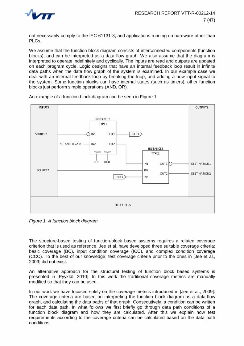
We assume that the function block diagram consists of interconnected components (functionblocks), and can be interpreted as a data flow graph. We also assume that the diagram isinterpreted to operate indefinitely and cyclically. The inputs are read and outputs are updatedon each program cycle. Logic designs that have an internal feedback loop result in infinitedata paths when the data flow graph of the system is examined. In our example case wedeal with an internal feedback loop by breaking the loop, and adding a new input signal tothe system. Some function blocks can have internal states (such as timers), other functionblocks just perform simple operations (AND, OR).
An example of a function block diagram can be seen in Figure 1.
Figure 1. A function block diagram
The structure-based testing of function-block based systems requires a related coveragecriterion that is used as reference. Jee et al. have developed three suitable coverage criteria:basic coverage (BC), input condition coverage (ICC), and complex condition coverage(CCC). To the best of our knowledge, test coverage criteria prior to the ones in [Jee et al.,2009] did not exist.
An alternative approach for the structural testing of function block based systems ispresented in [Pyykkö, 2010]. In this work the traditional coverage metrics are manuallymodified so that they can be used.
In our work we have focused solely on the coverage metrics introduced in [Jee et al., 2009].The coverage criteria are based on interpreting the function block diagram as a data-flowgraph, and calculating the data paths of that graph. Consecutively, a condition can be writtenfor each data path. In what follows we first briefly go through data path conditions of afunction block diagram and how they are calculated. After this we explain how testrequirements according to the coverage criteria can be calculated based on the data pathconditions.

RESEARCH REPORT VTT-R-00212-148 (47)
2.3.1 D-paths
In [Jee et al., 2009], the structural coverage criteria are based on a data path or d-path. Firstthe function block diagram F is defined as a tuple F = FBs, V, E , where FBs is a set offunction blocks, V is a set of variables, and E is a set of edges. Edge is defined as aconnection between two function blocks or a function block and a variable. Function blockscan be defined with respect to the edges. For example, the function block AND is defined as:eOUT = AND(eIN1, eIN2), where eOUT is the output edge of the function block and eIN1 and eIN2 arethe input edges.
A d-path is defined as a finite sequence e1, e2 … en of edges where all the edges succeedeach other. Since d-paths are finite, any internal feedback loop in a function block diagramneeds to be removed (see below for an example). A unit d-path is of length 2 and in the formei, eo . For example, the AND function block has two unit d-paths:
p1 = eIN1, eOUT
p2 = eIN2, eOUT
DP denotes the set of all d-paths from input edges to output edges. DPn denotes all d-pathsof length n. D-paths are denoted pij where i is the length of the path and j is a uniqueidentifier (if there are several d-paths of that length).
Example of a d-path:
p41 = input1, AND1.output, TON1.output1, output2
A d-path condition (DPC) is the condition along the d-path under which input value plays arole in computing the output. It can be defined recursively as follows:
( ) = , if 1( ) && FBC , ) if 2
where a function block condition FBC( en-1, en ) is defined for each function block.
Function block condition (FBC) is the value under which the value at the output edge eo isinfluenced by the value at the input edge ei. According to [Jee et al., 2009] there are fourtypes of FBCs:
1. All inputs always influence the value of the output. For example, in the basic additionfunction ADD, all inputs always influence the output. FBC is true for all unit d-paths.
2. Input value appears on output edge only in certain conditions. For example, the ANDfunction block: the function block condition FBC( eIN1, eOUT ) = ! eIN1 || eIN2.
3. Some or all input values are used in the output computation under specific condition.
4. Internal variables as well as inputs must be analysed to determine the output.
Truth tables help in determining the FBCs in these cases.
The DPC can be calculated recursively, and finally the expression can be transformed intoan expression with only input and internal variables by substituting intermediate variableswith the functions.

RESEARCH REPORT VTT-R-00212-149 (47)
2.3.2 Test coverage criteria
Based on the definition of DPC three different coverage criteria can be written for FBDprograms.
Basic coverage (BC)
Input condition coverage (ICC)
Complex condition coverage (CCC)
Basic coverage focuses on covering every d-path in the FBD program under test at leastonce. The BC criterion is satisfied iff there is a test in which the DPC is fulfilled for each d-path. BC is a straight-forward criterion but it can be ineffective in detecting logical errors e.g.when a wrong function block is used.
Input condition coverage (ICC) is satisfied by a set of test cases iff there are two tests for alld-paths: 1) A test in which the DPC is true and the input of the d-path is true, 2) a test inwhich the DPC is true and the input of the d-path is false.
Complex condition coverage (CCC) is satisfied when there is a test case for each edge alongthe d-path such that: 1) the DPC is satisfied and that edge is true, and 2) a test case in whichthat edge is false.
In practice, the coverage criterion and the data path conditions are used to generate a set oftest requirements that have to be fulfilled by one of the tests in order to achieve 100% testcoverage. Each test requirement is a logical formula consisting of signals of the functionblock diagram. If the formula is true in some test case at any time point, then the testrequirement is fulfilled.
2.4 Example system design description
As a running example, we utilize a small function-block based system, illustrated in Figure 2.The example is a stepwise shutdown system (modified from [Lötjönen, 2013] [Lötjönen et al.,2013]) that has been designed as a preventive safety system to drive a process into a normaloperating state without having to rapidly shut the process down. It can be triggered by aninput (e.g. high measurement value) or by the operator using a manual trip command. An 18s control cycle is used that consists of a 4 s control followed by 14 s idle time after which thecycle is started again if the measurements are still high. In addition, the operator can addfour second control cycles manually if the 14 second idle time seems too long. The designcontains an error: if the manual trip command is given during the 4 second control thesystem freezes until the input disappears. The design error is intentionally left to the exampleso that we can see whether the generated test sets will be able to detect the error.
RESEARCH REPORT VTT-R-00212-1410 (47)
Figure 2. Stepwise shutdown system
In this work the example system is used as a reference case to demonstrate how a set oftest cases can be generated according to given test coverage criteria.
2.5 Data path conditions for the example design
We interpret the example system as a data flow diagram, and use the coverage criteriadefined for function-block based systems: basic coverage (BC), input condition coverage(ICC), and complex condition coverage (CCC). All three of these metrics are used to producea set of test requirements. If all of these requirements are fulfilled by one of the tests in thetest set, the test set has 100 % coverage according to the criterion. All three coverage criteriaare based on the concept of data-path conditions. In order to use the criteria in our examplesystem we have to be able to determine the data-path conditions of the system.
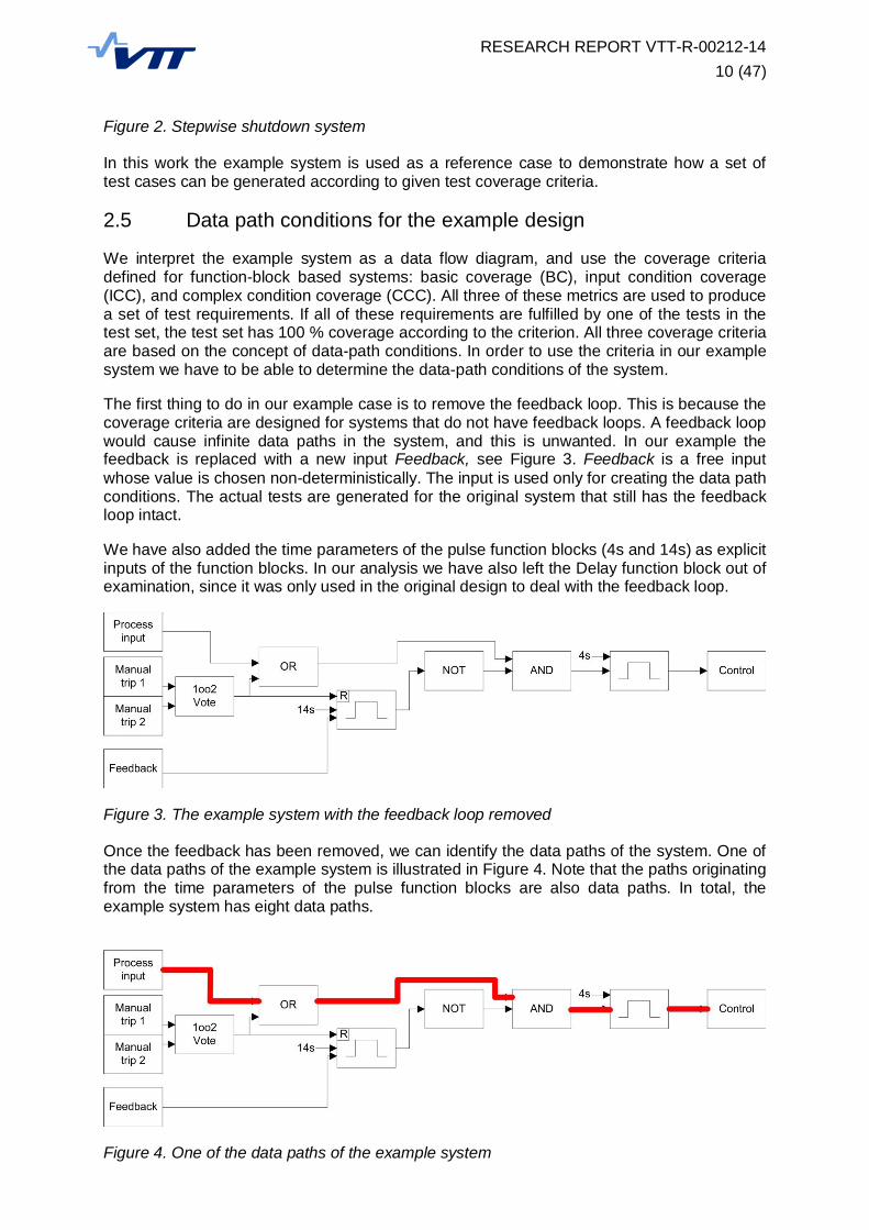
The first thing to do in our example case is to remove the feedback loop. This is because thecoverage criteria are designed for systems that do not have feedback loops. A feedback loopwould cause infinite data paths in the system, and this is unwanted. In our example thefeedback is replaced with a new input Feedback, see Figure 3. Feedback is a free inputwhose value is chosen non-deterministically. The input is used only for creating the data pathconditions. The actual tests are generated for the original system that still has the feedbackloop intact.
We have also added the time parameters of the pulse function blocks (4s and 14s) as explicitinputs of the function blocks. In our analysis we have also left the Delay function block out ofexamination, since it was only used in the original design to deal with the feedback loop.
Figure 3. The example system with the feedback loop removed
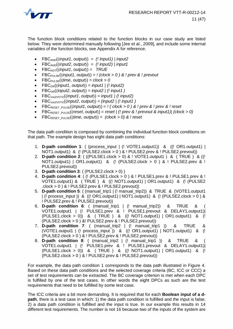
Once the feedback has been removed, we can identify the data paths of the system. One ofthe data paths of the example system is illustrated in Figure 4. Note that the paths originatingfrom the time parameters of the pulse function blocks are also data paths. In total, theexample system has eight data paths.
Figure 4. One of the data paths of the example system
RESEARCH REPORT VTT-R-00212-1411 (47)
The function block conditions related to the function blocks in our case study are listedbelow. They were determined manually following [Jee et al., 2009], and include some internalvariables of the function blocks, see Appendix A for reference.
FBCAND( input1, output ) = (! Input1) | input2 FBCAND( input2, output ) = (! input2) | input1 FBCNOT( input1, output ) = TRUE FBCPULSE( input1, output ) = ! (clock > 0 ) & ! prev & ! prevout FBCPULSE( time, output ) = clock > 0 FBCOR( input1, output ) = input1 | (! input2) FBCOR( input2, output ) = input2 | (! input1 ) FBC1oo2VOTE( input1, output ) = input1 | (! input2) FBC1oo2VOTE( input2, output ) = (input2 | (! input1 ) FBCRESET_PULSE( input1, output ) = ! ( clock > 0 ) & ! prev & ! prev & ! reset FBCRESET_PULSE( reset, output ) = reset | (! prev & ! prevout & input1)| (clock > 0) FBCRESET_PULSE( time, output ) = (clock > 0) & ! reset
The data path condition is composed by combining the individual function block conditions onthat path. The example design has eight data path conditions:
1. D-path condition 1: ( (process_input | (! VOTE1.output1)) & ((! OR1.output1) |NOT1.output1) & (! (PULSE2.clock > 0 ) & ! PULSE2.prev & ! PULSE2.prevout))
2. D-path condition 2: ( ((PULSE1.clock > 0) & ! VOTE1.output1 ) & ( TRUE ) & ((!NOT1.output1) | OR1.output1) & (! (PULSE2.clock > 0 ) & ! PULSE2.prev & !PULSE2.prevout))
3. D-path condition 3: ( (PULSE2.clock > 0) )4. D-path condition 4: ( (! (PULSE1.clock > 0 ) & ! PULSE1.prev & ! PULSE1.prev & !
VOTE1.output1) & ( TRUE ) & ((! NOT1.output1) | OR1.output1) & (! (PULSE2.clock > 0 ) & ! PULSE2.prev & ! PULSE2.prevout))
5. D-path condition 5: ( (manual_trip1 | (! manual_trip2)) & TRUE & (VOTE1.output1| (! process_input )) & ((! OR1.output1) | NOT1.output1) & (! (PULSE2.clock > 0 ) &! PULSE2.prev & ! PULSE2.prevout))
6. D-path condition 6: ( (manual_trip1 | (! manual_trip2)) & TRUE & (VOTE1.output1 | (! PULSE1.prev & ! PULSE1.prevout & DELAY1.output1)|(PULSE1.clock > 0)) & ( TRUE ) & ((! NOT1.output1) | OR1.output1) & (!(PULSE2.clock > 0 ) &! PULSE2.prev & ! PULSE2.prevout))
7. D-path condition 7: ( (manual_trip2 | (! manual_trip1 )) & TRUE &(VOTE1.output1 | (! process_input )) & ((! OR1.output1) | NOT1.output1) & (!(PULSE2.clock > 0 ) & ! PULSE2.prev & ! PULSE2.prevout))
8. D-path condition 8: ( (manual_trip2 | (! manual_trip1 )) & TRUE & (VOTE1.output1 | (! PULSE1.prev & ! PULSE1.prevout & DELAY1.output1)|(PULSE1.clock > 0)) & ( TRUE ) & ((! NOT1.output1) | OR1.output1) & (!(PULSE2.clock > 0 ) & ! PULSE2.prev & ! PULSE2.prevout))
For example, the data path condition 1 corresponds to the data path illustrated in Figure 4.Based on these data path conditions and the selected coverage criteria (BC, ICC or CCC) aset of test requirements can be extracted. The BC coverage criterion is met when each DPCis fulfilled by one of the test cases. In other words the eight DPCs as such are the testrequirements that need to be fulfilled by some test case.
The ICC criteria are a bit more demanding. It is required that for each Boolean input of a d-path, there is a test case in which: 1) the data path condition is fulfilled and the input is false;2) a data path condition is fulfilled and the input is true. In our example this results in 14different test requirements. The number is not 16 because two of the inputs of the system are
RESEARCH REPORT VTT-R-00212-1412 (47)
not Boolean, and thus the data paths that originate from these inputs produce only one testrequirement instead of two.
The CCC criteria are even more demanding. It is required that for each Boolean variablewithin a d-path, there is a test case in which: 1) the data path condition is fulfilled and thevariable is false; 2) a data path condition is fulfilled and the variable is true. For the data pathcondition corresponding to the data path in Figure 3, it would additionally be required thate.g. the signal from the OR function block to the AND function block is true/false in some testcase while the data path condition holds. In our example system the CCC criterion results in80 test requirements.
Once the desired coverage criterion is selected and the relevant test requirements areproduced we need to define test cases that fulfil these requirements. In simple designs thismay be straight-forward. However, in case of complex designs with timers and feedback it isnot so simple. The reason for this is that the test requirement may require the timer functionblocks of the system to be in certain states, and sometimes it can be very difficult to find outhow to get to such a system state. Sometimes reaching a system state may be impossibledue to some constraints outside the data path.
2.6 Automatic test set generation concept
2.6.1 General concept description
In this concept the test cases are identified using model checking. In particular, the testcases are counter-examples output by the model checking tool. A requirement for thisapproach is that the examined system has been modelled as a model checking model. Amethodology for modelling function block diagram designs already exists; see e.g. [Pakonenet al., 2013].
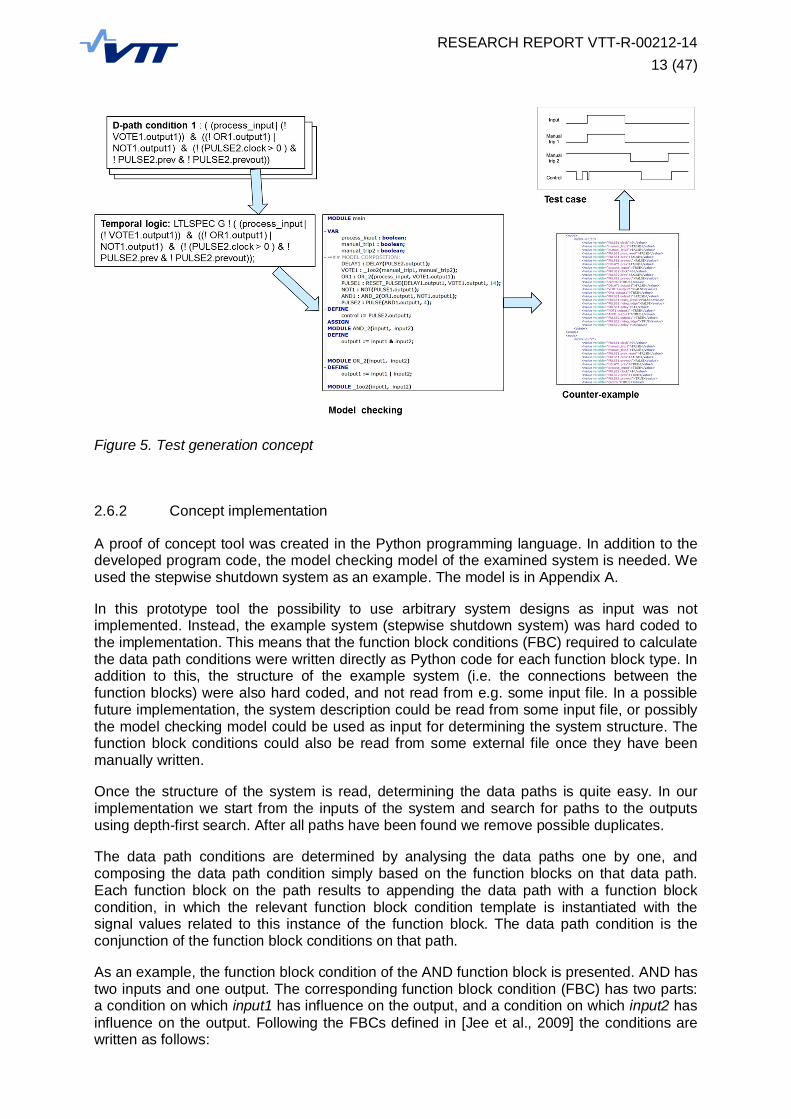
Once the desired coverage criterion has been selected and the set of test requirements isdeduced, the test case identification can begin. Each test requirement is transformed into atemporal logic clause stating that the state required by the test requirement cannot bereached. This transformation is quite simple since the test requirement is already a suitablelogical formula. Once the temporal logic formula has been produced we check whether itholds on the model checking model. If a path exists to a state in which the test requirement isfulfilled, it is given as a counter-example. The counter-example can be used to define testcases that achieve high coverage. The general idea of the test generation concept isillustrated in Figure 5.
RESEARCH REPORT VTT-R-00212-1413 (47)
Figure 5. Test generation concept
2.6.2 Concept implementation
A proof of concept tool was created in the Python programming language. In addition to thedeveloped program code, the model checking model of the examined system is needed. Weused the stepwise shutdown system as an example. The model is in Appendix A.
In this prototype tool the possibility to use arbitrary system designs as input was notimplemented. Instead, the example system (stepwise shutdown system) was hard coded tothe implementation. This means that the function block conditions (FBC) required to calculatethe data path conditions were written directly as Python code for each function block type. Inaddition to this, the structure of the example system (i.e. the connections between thefunction blocks) were also hard coded, and not read from e.g. some input file. In a possiblefuture implementation, the system description could be read from some input file, or possiblythe model checking model could be used as input for determining the system structure. Thefunction block conditions could also be read from some external file once they have beenmanually written.
Once the structure of the system is read, determining the data paths is quite easy. In ourimplementation we start from the inputs of the system and search for paths to the outputsusing depth-first search. After all paths have been found we remove possible duplicates.
The data path conditions are determined by analysing the data paths one by one, andcomposing the data path condition simply based on the function blocks on that data path.Each function block on the path results to appending the data path with a function blockcondition, in which the relevant function block condition template is instantiated with thesignal values related to this instance of the function block. The data path condition is theconjunction of the function block conditions on that path.
As an example, the function block condition of the AND function block is presented. AND hastwo inputs and one output. The corresponding function block condition (FBC) has two parts:a condition on which input1 has influence on the output, and a condition on which input2 hasinfluence on the output. Following the FBCs defined in [Jee et al., 2009] the conditions arewritten as follows:
RESEARCH REPORT VTT-R-00212-1414 (47)
FBC input1, output1 = (! input1) | input2
FBC input2, output1 = (! input2) | input1
In our implementation code these conditions are stored in a format in which the variablesinput1 and input2 are replaced with placeholders that are replaced with the variables of theAND function block instance. In implementation code the FBC is stored as:
“ ((! %i0%) | %i1%) "
" ((! %i1%) | %i0%) "
As the data path condition is being created the temporary variables i0 and i1 are replaced.For example, in our running example (see Appendix A) in the case of the AND1 functionblock instance the input variables would be replaced with “OR1.output” and “NOT1.output1”.
It is also quite simple to create the set of test requirements. The set of data path conditions issupplemented with the constraints demanded by the different coverage criteria. Finally theset of test requirements can be transformed into usable temporal logic formulas by addingthe universal “globally” operator in the beginning of the negated test requirement clause. Inthe syntax of the model checking tool NuSMV the resulting formula is of the form:
LTLSPEC G ! (test-requirement);
Each test requirement can be transformed into a temporal logic formula. The model checkingtool can then be used to produce a counter-example (to be used as a test case)corresponding to each formula (if one exists).
One disadvantage of the above mentioned method is that a test case is created for each testrequirement separately. Often it is possible to satisfy the test requirements using fewer testcases, so that a single test case fulfils multiple test requirements. The minimization of thenumber of test cases is discussed below.
2.6.3 Test case optimization
For the CCC test coverage metrics, our running example produces 80 separate testrequirements. Following our test generation concept this would lead to 80 test cases for onesimple logic diagram. Fortunately, the number of test cases can be drastically decreased. Itis possible to create test cases that fulfil multiple test requirements at once. It may even bepossible to fulfil all requirements in one complex test case.
In practice this can be done by combining two (or several) temporal logic formulas into asingle temporal logic formula that covers all the associated test requirements. As anexample, assume we have two test requirements: test_req_1 and test_req_2. Thecorresponding temporal logic formula for these two test requirements in NuSMV would be ofthe form:
LTLSPEC G ! ( test_req_1 ) | G ! ( test_req_2 );
In practice the formula states that no path exists in which both of the test requirements aretrue at some time point. If such a path exists it will be output by the model checking tool as acounter-example.
Now it is possible for example to create a single temporal logic formula encompasses all ofthe test requirements. However, a test that fulfils all test requirements may be infeasible, orjust very complex, or consisting of very many time steps. In some cases a single testrequirement is infeasible, and these cases should also be detected and sorted out.

RESEARCH REPORT VTT-R-00212-1415 (47)
We implemented a simple greedy test case optimization algorithm that begins with the firsttest requirement and determines whether a test case for that single test requirement isfeasible. If it is feasible we look at the counter-example that was output and store the lengthof that counter-example. Then we attach a new test requirement to the examined set of testrequirements, and find out whether a counter-example of the same length that fulfils all testrequirements in the set is feasible. If such a counter-example is still possible we continue byattempting to add even more test requirements to the set. If the counter-example becomesinfeasible, we exclude the most recent test requirement and continue by adding one from theset of unexamined test requirements. Once all test requirements have been gone through,we have a single test case that fulfils n out of the N test requirements. The process is thenrepeated with the N - n remaining test requirement until every test requirement is covered bysome test case, or it has been determined that the test requirement cannot be fulfilled. Thissimple greedy optimization in the example system leads to three test cases for the 80 testrequirements that are produced by the CCC coverage metric.
2.7 Results
Our Python implementation of the tool was run, and the tests sets according to the differentcoverage metrics (BC, ICC, CCC) were generated. The greedy test optimization asdescribed in Section 2.6.3 was used. The testing of the method was done on a PC with IntelCore i7 Q740 processor and 3 GB of RAM. For model checking, NuSMV version 2.5.4 wasused. The clock cycle used for the model checking of the example system was 1s.
The basic coverage (BC) metric resulted in 8 test requirements on the example system. Thetest requirements are equivalent to the data path conditions of the system:
Test requirement 1: ( (process_input | (! VOTE1.output1)) & ((! OR1.output1) |NOT1.output1) & (! (PULSE2.clock > 0 ) & ! PULSE2.prev & ! PULSE2.prevout))
Test requirement 2: ( ((PULSE1.clock > 0) & ! VOTE1.output1 ) & ( TRUE ) & ((!NOT1.output1) | OR1.output1) & (! (PULSE2.clock > 0 ) & ! PULSE2.prev & !PULSE2.prevout))
Test requirement 3: ( (PULSE2.clock > 0) )
Test requirement 4: ( (! (PULSE1.clock > 0 ) & ! PULSE1.prev & ! PULSE1.prev & !VOTE1.output1) & ( TRUE ) & ((! NOT1.output1) | OR1.output1) & (!(PULSE2.clock > 0 ) & ! PULSE2.prev & ! PULSE2.prevout))
Test requirement 5: ( (manual_trip1 | (! manual_trip2)) & TRUE & (VOTE1.output1| (! process_input )) & ((! OR1.output1) | NOT1.output1) & (! (PULSE2.clock > 0 ) &! PULSE2.prev & ! PULSE2.prevout))
Test requirement 6: ( (manual_trip1 | (! manual_trip2)) & TRUE & (VOTE1.output1 | (! PULSE1.prev & ! PULSE1.prevout & DELAY1.output1)|(PULSE1.clock > 0)) & ( TRUE ) & ((! NOT1.output1) | OR1.output1) & (!(PULSE2.clock > 0 ) & ! PULSE2.prev & ! PULSE2.prevout))
Test requirement 7: ( (manual_trip2 | (! manual_trip1 )) & TRUE &(VOTE1.output1 | (! process_input )) & ((! OR1.output1) | NOT1.output1) & (!(PULSE2.clock > 0 ) & ! PULSE2.prev & ! PULSE2.prevout))
Test requirement 8: ( (manual_trip2 | (! manual_trip1 )) & TRUE & (VOTE1.output1 | (! PULSE1.prev & ! PULSE1.prevout & DELAY1.output1)|(PULSE1.clock > 0)) & ( TRUE ) & ((! NOT1.output1) | OR1.output1) & (!(PULSE2.clock > 0 ) & ! PULSE2.prev & ! PULSE2.prevout))

RESEARCH REPORT VTT-R-00212-1416 (47)
Based on the greedy optimization, two test cases were created that fulfil the testrequirements. Test 1 satisfies test requirements 1 and 4, while test 2 satisfies the rest of therequirements (2, 3, 5, 6, 7, and 8). Using our implementation the time needed to generate thetests was 2.9 seconds in total, including test requirement generation, model checking andoptimization. The resulting two test cases are as follows:
BC Test case 1:
Time point 1:
o INPUT: Process input = TRUE
o INPUT: Manual trip1 = FALSE
o INPUT: Manual trip2 = FALSE
o EXPECTED OUTPUT: Control = TRUE
BC Test case 2:
Time point 1:
o INPUT: Process input = TRUE
o INPUT: Manual trip1 = TRUE
o INPUT: Manual trip2 = TRUE
o EXPECTED OUTPUT: Control = TRUE
Time point 2:
o INPUT: Process input = TRUE
o INPUT: Manual trip1 = TRUE
o INPUT: Manual trip2 = TRUE
o EXPECTED OUTPUT: Control = TRUE
Time point 3:
o INPUT: Process input = TRUE
o INPUT: Manual trip1 = TRUE
o INPUT: Manual trip2 = TRUE
o EXPECTED OUTPUT: Control = TRUE
Time point 4:
o INPUT: Process input = TRUE
o INPUT: Manual trip1 = TRUE
o INPUT: Manual trip2 = TRUE
o EXPECTED OUTPUT: Control = TRUE

RESEARCH REPORT VTT-R-00212-1417 (47)
Time point 5:
o INPUT: Process input = TRUE
o INPUT: Manual trip1 = TRUE
o INPUT: Manual trip2 = TRUE
o EXPECTED OUTPUT: Control = TRUE
Time point 6:
o INPUT: Process input = TRUE
o INPUT: Manual trip1 = TRUE
o INPUT: Manual trip2 = TRUE
o EXPECTED OUTPUT: Control = FALSE
Time point 7:
o INPUT: Process input = TRUE
o INPUT: Manual trip1 = FALSE
o INPUT: Manual trip2 = FALSE
o EXPECTED OUTPUT: Control = FALSE
The intermediate values of the function blocks are not listed in the test cases since thevalues are determined solely on the input signal values. Test case 1 is a simple test caseconsisting of a single time point in which the control output should be set when the processinput is true. The second test case ensures that the control output eventually becomes falseafter the pulse and that the manual trip commands do not cause anything unexpected.
The input condition coverage (ICC) metric resulted in 14 test requirements on the examplesystem. The test requirements are listed in Appendix B. Three test cases were generatedbased on the test requirements. Test 1 satisfies test requirements 1 and 6. Test 2 satisfiestest requirements 2, 8 and 12. Test 3 satisfies test requirements 3, 4, 7, 9, 10, 11, 13 and 14.Test requirement 5 was infeasible meaning that a state in which the requirement is truecannot be reached in the example system. Test requirement 5 is infeasible because itrequires that the feedback signal is true while the internal memory indicating the previouscontrol output value is false. In the actual system where the feedback loop is intact these twosignals are the same signal which causes the requirement to be infeasible. The test cases forthe ICC coverage metric are as follows:
ICC Test case 1:
Time point 1:
o INPUT: Process input = TRUE
o INPUT: Manual trip1 = FALSE
o INPUT: Manual trip2 = FALSE
o EXPECTED OUTPUT: Control = TRUE

RESEARCH REPORT VTT-R-00212-1418 (47)
ICC Test case 2:
Time point 1:
o INPUT: Process input = FALSE
o INPUT: Manual trip1 = FALSE
o INPUT: Manual trip2 = FALSE
o EXPECTED OUTPUT: Control = FALSE
ICC Test case 3:
Time point 1:
o INPUT: Process input = TRUE
o INPUT: Manual trip1 = TRUE
o INPUT: Manual trip2 = TRUE
o EXPECTED OUTPUT: Control = TRUE
Time point 2:
o INPUT: Process input = TRUE
o INPUT: Manual trip1 = FALSE
o INPUT: Manual trip2 = TRUE
o EXPECTED OUTPUT: Control = TRUE
Time point 3:
o INPUT: Process input = TRUE
o INPUT: Manual trip1 = TRUE
o INPUT: Manual trip2 = FALSE
o EXPECTED OUTPUT: Control = TRUE
Time point 4:
o INPUT: Process input = TRUE
o INPUT: Manual trip1 = FALSE
o INPUT: Manual trip2 = TRUE
o EXPECTED OUTPUT: Control = TRUE
Time point 5:
o INPUT: Process input = TRUE
o INPUT: Manual trip1 = TRUE

RESEARCH REPORT VTT-R-00212-1419 (47)
o INPUT: Manual trip2 = FALSE
o EXPECTED OUTPUT: Control = TRUE
Time point 6:
o INPUT: Process input = TRUE
o INPUT: Manual trip1 = TRUE
o INPUT: Manual trip2 = FALSE
o EXPECTED OUTPUT: Control = FALSE
Time point 7:
o INPUT: Process input = TRUE
o INPUT: Manual trip1 = FALSE
o INPUT: Manual trip2 = FALSE
o EXPECTED OUTPUT: Control = FALSE
Test case 1 is similar to the test case 1 generated for BC. The second test case does notoccur in the BC tests. The second test case makes sure that the control output is not setwhen the inputs are false. The third test case is again quite similar to BC test case 2 exceptthat the manual trip commands alternate. The time needed to generate the ICC test caseswas 6.9 seconds including test requirement generation, model checking and optimization.
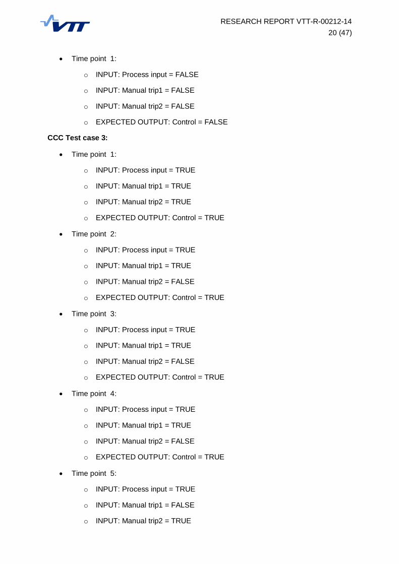
The complex condition coverage (CCC) metric results in 80 test requirements. Because ofthe large amount of test requirements, the clauses are not included in this report. Three testcases were generated based on the test requirements. Test 1 satisfies test requirements 1,3, 5, 7, 20, 22, 23, 25 and 27. Test 2 satisfies test requirements 2, 4, 6, 8, 30, 32, 34, 36, 38,40, 56, 58, 60, 62, 64 and 66. Test 3 satisfies test requirements 9, 12, 14, 16, 17, 29, 31, 33,35, 37, 39, 41, 42, 43, 44, 45, 46, 47, 48, 49, 50, 51, 52, 53, 54, 55, 57, 59, 61, 63, 65, 67,68, 69, 70, 71, 72, 73, 74, 75, 76, 77, 78, 79 and 80. Test requirements 10, 11, 13, 15, 18,19, 21, 24, 26, and 28 were infeasible, i.e. the condition could not be reached in the examplesystem. As an example of the infeasible cases, test requirement 10 is infeasible because itrequires that the output of a pulse function block (PULSE1) is false while the internal clock ofthe pulse is running. This cannot occur in the system because the output is set whenever theclock is running. The CCC test cases are as follows:
CCC Test case 1:
Time point 1:
o INPUT: Process input = TRUE
o INPUT: Manual trip1 = FALSE
o INPUT: Manual trip2 = FALSE
o EXPECTED OUTPUT: Control = TRUE
CCC Test case 2:
RESEARCH REPORT VTT-R-00212-1420 (47)
Time point 1:
o INPUT: Process input = FALSE
o INPUT: Manual trip1 = FALSE
o INPUT: Manual trip2 = FALSE
o EXPECTED OUTPUT: Control = FALSE
CCC Test case 3:
Time point 1:
o INPUT: Process input = TRUE
o INPUT: Manual trip1 = TRUE
o INPUT: Manual trip2 = TRUE
o EXPECTED OUTPUT: Control = TRUE
Time point 2:
o INPUT: Process input = TRUE
o INPUT: Manual trip1 = TRUE
o INPUT: Manual trip2 = FALSE
o EXPECTED OUTPUT: Control = TRUE
Time point 3:
o INPUT: Process input = TRUE
o INPUT: Manual trip1 = TRUE
o INPUT: Manual trip2 = FALSE
o EXPECTED OUTPUT: Control = TRUE
Time point 4:
o INPUT: Process input = TRUE
o INPUT: Manual trip1 = TRUE
o INPUT: Manual trip2 = FALSE
o EXPECTED OUTPUT: Control = TRUE
Time point 5:
o INPUT: Process input = TRUE
o INPUT: Manual trip1 = FALSE
o INPUT: Manual trip2 = TRUE
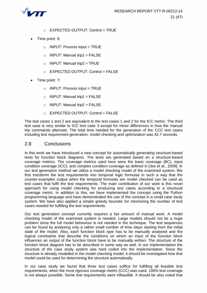
RESEARCH REPORT VTT-R-00212-1421 (47)
o EXPECTED OUTPUT: Control = TRUE
Time point 6:
o INPUT: Process input = TRUE
o INPUT: Manual trip1 = FALSE
o INPUT: Manual trip2 = TRUE
o EXPECTED OUTPUT: Control = FALSE
Time point 7:
o INPUT: Process input = TRUE
o INPUT: Manual trip1 = FALSE
o INPUT: Manual trip2 = FALSE
o EXPECTED OUTPUT: Control = FALSE
The test cases 1 and 2 are equivalent to the test cases 1 and 2 for the ICC metric. The thirdtest case is very similar to ICC test case 3 except for minor differences in how the manualtrip commands alternate. The total time needed for the generation of the CCC test casesincluding test requirement generation, model checking and optimization was 42,7 seconds.
2.8 Conclusions
In this work we have introduced a new concept for automatically generating structure-basedtests for function block diagrams. The tests are generated based on a structure-basedcoverage metrics. The coverage metrics used here were the basic coverage (BC), inputcondition coverage (ICC), and complex condition coverage as defined in [Jee et al., 2009]. Inour test generation method we utilize a model checking model of the examined system. Wefirst transform the test requirements into temporal logic formulas in such a way that thecounter-examples output when the temporal formulas are model checked can be used astest cases that fulfil the test requirements. The main contribution of our work is this novelapproach for using model checking for producing test cases according to a structuralcoverage metric. In addition to this, we have implemented the concept using the Pythonprogramming language and have demonstrated the use of the concept in a small case studysystem. We have also applied a simple greedy heuristic for minimizing the number of testcases needed for fulfilling the test requirements.
Our test generation concept currently requires a fair amount of manual work. A modelchecking model of the examined system is needed. Large models should not be a hugeproblem since the full model behaviour is not needed in the technique. The test sequencescan be found by analysing only a rather small number of time steps starting from the initialstate of the model. Also, each function block type has to be manually analysed and thelogical constraints that describe the conditions on which an input of the function blockinfluences an output of the function block have to be manually written. The structure of thefunction block diagram has to be described in some way as well. In our implementation thestructure of the case study system was hard coded into the implementation. Since thestructure is already modelled in the model checking model, it should be investigated how thatmodel could be used for determining the structure automatically.
In our case study we found that three test cases suffice for fulfilling all feasible testrequirements, when the most rigorous coverage metric (CCC) was used. 100% test coverageis not always possible. Some test requirements were infeasible. It should be also noted that
RESEARCH REPORT VTT-R-00212-1422 (47)
the use of the most rigorous coverage metric CCC produced almost identical test caseswhen compared to the less rigorous ICC coverage metric. Our case study was perhaps toosimple so that the intricacies of the CCC coverage metric could not be seen. The most basiccoverage metric (BC) resulted in two test cases.
The case study system was chosen because it includes a design error: if the manual tripcommand is given during the 4 second control the system freezes until the input disappears.The generated test cases do express this kind of behaviour, the manual trip is indeedpressed in during the 4s control in the test cases. However, the generated test cases do notdemonstrate the effect of the wrong operator action, namely the freeze of the output cannotbe seen in the short test case sequences. We speculate that if the internal variables of thepulse blocks were interpreted as input signals in the coverage metric calculations, the freezeof the control could possibly be seen in the generated test cases. We leave this question forfuture work.
Finally, we would like to note the difference in the definition of the function block conditions ofthe coverage metrics by [Jee et al., 2009], and the input-output condition as defined in e.g.the MCDC coverage metric. In [Jee et al., 2009] the function block conditions (FBCs) arewritten as a pair of constraints. The constraints express the fact that other inputs do not haveinfluence on the output. One constraint is for when the input is 0 and the other constraint isfor when the input signal is 1. The FBC is the combination of these constraints. As anexample, the FBC for one of the inputs of an AND function block is:
FBC input1, output1 = (! input1) | input2
It states that when input1 is not true, it has influence on the output. If input1 is true, itinfluences the output only when input2 is true as well. A similar input-output influence relationis defined in the MCDC coverage metric. In MCDC the influence relation is somewhatdifferent: input has influence on the output when flipping of the input value, also flips theoutput value. The related constraint describes the situation where this always occurs. If theFBC for the AND function block was written based on this definition, it would be:
FBC input1, output1 = input2
The input1 has influence on the output only when the other input is true. The difference inthese two definitions is the case where both inputs are false. According to the [Jee et al.,2009] definition, input1 has influence on the output since input1 is one of the inputs that arefalse. According to the MCDC definition input1 does not have influence on the output.
In future, we plan to determine a way to generate the function block conditions automatically.Using the MCDC definition for the input-output relations might be easier for automaticgeneration purposes. We also plan to use the model checking model for determining thefunction block diagram structure so that the amount of manual work and hard coding isminimized. Some test case optimization heuristics could also be tried out, as well as a parserthat produces the test cases in a more readable format.
3. Using model checking for verification of different FPGA designphases
3.1 Introduction
Field-programmable gate array (FPGA) is a programmable integrated circuit that consists ofa set of logic gates and wiring between them. Unlike in traditional application specificintegrated circuits (ASIC) the connections between circuit gates can be configured by theuser instead of the manufacturer. The FPGA technology is still rather new in the nuclear

RESEARCH REPORT VTT-R-00212-1423 (47)
power industry for implementing safety system application functions. Power utilities, systemvendors, and regulators of different countries have their own views on how to license,develop, and verify FPGA applications.
Developing applications for FPGAs is quite similar to developing software. However, the end-product can be considered as hardware because FPGAs do not have an operating system ora set of instructions that are executed. Instead a static configuration of logic gatesimplements the desired functionality. The product is often considered less complex, eventhough the development process is more complex than software development. [EPRI, 2009]
Due to the technology’s nature, the FPGA design life cycle is somewhat different from thetraditional software or hardware development life cycle, by having some additional designphases. Also, various non-certified software tools are used in each design phase forautomatically generating the next design phase. In safety-critical domains we have to becertain that this chain of transformations produces a correct final product.
Many V&V methods are currently used, simulation being one example. Formal methods havebeen used as well. Model checking is a formal method developed to verify the correctfunctioning of a system design model by examining all of its possible behaviours. The modelsused in model checking are quite similar to those used in simulation. However, unlikesimulation, model checkers examine the behaviour of the system design with all inputsequences and compare it with the system specification. Model checking has its roots inhardware verification where it first proved to be effective for verifying large and complexintegrated circuits [Burch et al., 1992; Fix, 2008].
In this section we document our preliminary experiences of using model checking foranalysing FPGA based implementation. We especially have attempted to use the variousdesign phases of the FPGA design life cycle as input for model checking. The objective ofthis work has been to find out how model checking could be used to analyse some of thelow-level representations of the system, and whether this kind of analysis is worthwhile andreasonable. We have used the case study presented in [Lötjönen, 2013] and created variousmodels corresponding to the different design phases of that case study system.
3.2 FPGA development life-cycle
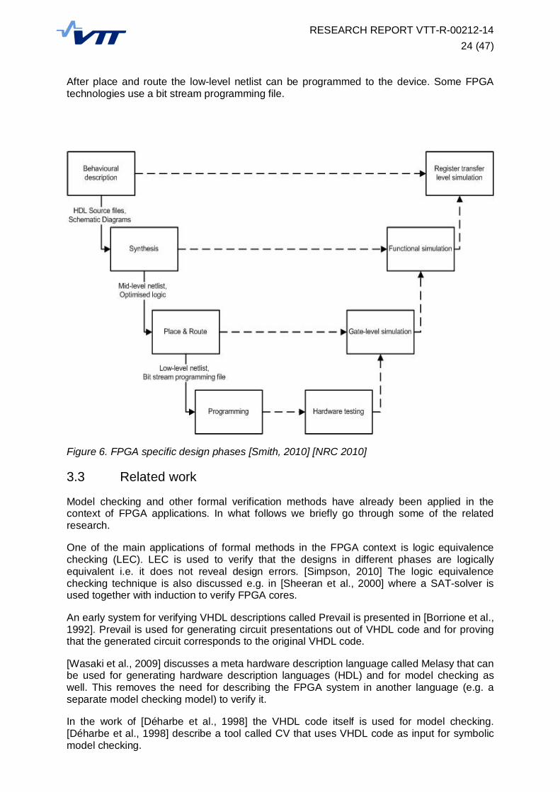
The FPGA specific design phases of an FPGA based application are illustrated in Figure 6.
The early design phases – such as requirements specification, architectural design, anddetailed design – are quite similar to the design phases of more traditional software basedautomation systems, and are therefore not illustrated in the figure.
The first FPGA specific design phase after detailed design is behavioural description. Thebehavioural description typically means that the desired system is described using ahardware description language (HDL). One example of a hardware description language isVHDL (very high speed integrated circuit hardware description language). The followingdesign phase is synthesis, in which the description is translated into a more hardwareoriented format, describing the design implementation in terms of logic gates. The output ofthe synthesis phase is a mid-level netlist that describes how the design is implemented usinglogic gates and memories. This netlist is typically produced using a software tool.
The next design phase is place and route, in which the mid-level netlist is adjusted to theparticular FPGA device. The product of the design phase is a low-level netlist that hasinformation the particular gates used for implementing the design. In this phase the timing ofthe signals have to be taken into consideration as well. The implementation of the designmust be such that the gates are always able to receive their inputs signals on time, and thatdifferences in input signal propagation times do not cause unwanted output states, i.e. norace conditions exist in the implementation of the logic.
RESEARCH REPORT VTT-R-00212-1424 (47)
After place and route the low-level netlist can be programmed to the device. Some FPGAtechnologies use a bit stream programming file.
Figure 6. FPGA specific design phases [Smith, 2010] [NRC 2010]
3.3 Related work
Model checking and other formal verification methods have already been applied in thecontext of FPGA applications. In what follows we briefly go through some of the relatedresearch.
One of the main applications of formal methods in the FPGA context is logic equivalencechecking (LEC). LEC is used to verify that the designs in different phases are logicallyequivalent i.e. it does not reveal design errors. [Simpson, 2010] The logic equivalencechecking technique is also discussed e.g. in [Sheeran et al., 2000] where a SAT-solver isused together with induction to verify FPGA cores.
An early system for verifying VHDL descriptions called Prevail is presented in [Borrione et al.,1992]. Prevail is used for generating circuit presentations out of VHDL code and for provingthat the generated circuit corresponds to the original VHDL code.
[Wasaki et al., 2009] discusses a meta hardware description language called Melasy that canbe used for generating hardware description languages (HDL) and for model checking aswell. This removes the need for describing the FPGA system in another language (e.g. aseparate model checking model) to verify it.
In the work of [Déharbe et al., 1998] the VHDL code itself is used for model checking.[Déharbe et al., 1998] describe a tool called CV that uses VHDL code as input for symbolicmodel checking.
RESEARCH REPORT VTT-R-00212-1425 (47)
Commercial model checking tools exist as well. One example is IBM’s RuleBase. [Beer et al.,1996] [Daumas et al., 2012] RuleBase uses a version of the model checking tool SMV as itsverification engine. The tool supports standard commonly used hardware descriptionlanguages such as VHDL.
3.4 Case study description
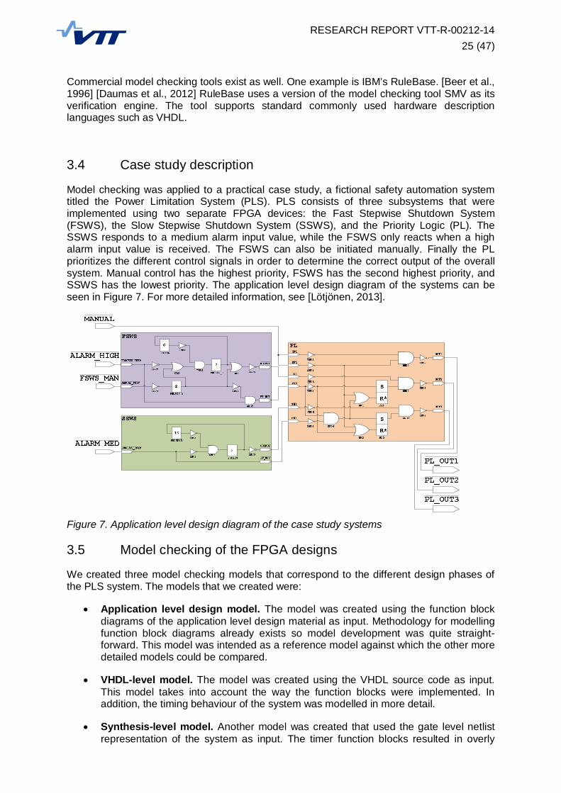
Model checking was applied to a practical case study, a fictional safety automation systemtitled the Power Limitation System (PLS). PLS consists of three subsystems that wereimplemented using two separate FPGA devices: the Fast Stepwise Shutdown System(FSWS), the Slow Stepwise Shutdown System (SSWS), and the Priority Logic (PL). TheSSWS responds to a medium alarm input value, while the FSWS only reacts when a highalarm input value is received. The FSWS can also be initiated manually. Finally the PLprioritizes the different control signals in order to determine the correct output of the overallsystem. Manual control has the highest priority, FSWS has the second highest priority, andSSWS has the lowest priority. The application level design diagram of the systems can beseen in Figure 7. For more detailed information, see [Lötjönen, 2013].
Figure 7. Application level design diagram of the case study systems
3.5 Model checking of the FPGA designs
We created three model checking models that correspond to the different design phases ofthe PLS system. The models that we created were:
Application level design model. The model was created using the function blockdiagrams of the application level design material as input. Methodology for modellingfunction block diagrams already exists so model development was quite straight-forward. This model was intended as a reference model against which the other moredetailed models could be compared.
VHDL-level model. The model was created using the VHDL source code as input.This model takes into account the way the function blocks were implemented. Inaddition, the timing behaviour of the system was modelled in more detail.
Synthesis-level model. Another model was created that used the gate level netlistrepresentation of the system as input. The timer function blocks resulted in overly

RESEARCH REPORT VTT-R-00212-1426 (47)
complex implementation that could not be easily modelled. Consequently only the PLsubsystem was modelled on this level.
The model checking tool that was used in the work was NuSMV [Cavada et al., 2010]. Thetool has previously been used in many research case studies at VTT [Lahtinen et al., 2012].The model checked requirements were formalised using a formal logic called linear temporallogic (LTL). In what follows we go through these model variants in more detail.
3.5.1 Application level design model
First, a small function block library was created based on the function blocks that were usedin the PLS system. After this all three subsystems of PLS were modelled by creatinginstances of the function blocks and creating the connections between the function blocksaccording to the design. As an example, the model code for the PL subsystem is as follows:
MODULE PL(IN1, EN1, IN2, EN2, IN3, EN3)VAR
INV1 : INV(IN1);INV2 : INV(EN1);INV3 : INV(IN2);INV4 : INV(EN2);INV5 : INV(IN3);INV6 : INV(EN3);
AND1 : AND(INV1.OUTPUT, INV2.OUTPUT);AND2 : AND(INV3.OUTPUT, RL1.OUTPUT);AND3 : AND(INV5.OUTPUT, RL2.OUTPUT);AND4 : AND(EN2, INV6.OUTPUT);
OR1 : OR(INV2.OUTPUT, AND4.OUTPUT);OR2 : OR(INV2.OUTPUT, INV4.OUTPUT);RL1 : SR_FLIPFLOP(INV4.OUTPUT, OR1.OUTPUT);RL2 : SR_FLIPFLOP(AND4.OUTPUT, OR2.OUTPUT);
INV7 : INV(AND1.OUTPUT);INV8 : INV(AND2.OUTPUT);INV9 : INV(AND3.OUTPUT);
DEFINEOUT1 := INV7.OUTPUT;OUT2 := INV8.OUTPUT;OUT3 := INV9.OUTPUT;
ASSIGN
This memory elements used in the PL implementation were modelled here as set-reset flip-flops. The model code for the used flip-flop is below:
MODULE SR_FLIPFLOP(set, reset)VARmem : boolean;DEFINE
OUTPUT := casereset : FALSE;set : TRUE;TRUE : mem;
esac;ASSIGNinit(mem) := FALSE;next(mem) := OUTPUT;

RESEARCH REPORT VTT-R-00212-1427 (47)
The model corresponding to the application level design level was built so that the systemhas no clock signal in the model. In NuSMV, the notion of time is discrete, meaning that timeis interpreted to consist of separate steps that follow each other. The modelled systemoperates as a single synchronous unity, in which every function block operates once during asingle time point. For individual function blocks this means that processing the inputs andproducing the corresponding outputs happens immediately, i.e. no time delays are modelledfor intrinsic calculations of the logic. As an example, see the implementation of the ANDfunction block. The output of the AND block is simply a macro definition based on the twoinputs, no variables or time delays are involved:
MODULE AND(input1, input2)VARDEFINEOUTPUT := input1 & input2;ASSIGN
Only a few requirements were verified on the model since the main focus of the work was inmodelling of the system. The time needed for model checking was less than a second. Thechecked requirements were (Note: the negations used in LTL stem from the active lowdesign of the system):
1. While the input Manual is inactive, while input high Alarm is inactive, while Mediumalarm is active, the output PL_OUT3 of the PL subsystem shall follow the outputPT_OUT of the SSWS subsystem. The requirement can be formalized in LTL:
G (! MANUAL & ! ALARM_HIGH & ALARM_MED -> (PL_OUT3 <->SSWS1.PT_OUT))
2. While the Manual input is active, the PL_OUT1 of the PL system shall be active. Therequirement can be formalized in LTL:
G (MANUAL -> PL_OUT1)
3. While the Manual control command and the Manual control enable signal are active,the PL_OUT1 output shall be active. The requirement can be formalized in LTL:
G ((!IN1 & !EN1) -> ! PL_OUT1)
4. While IN3 signal and the EN3 enable signal and the PL_OUT1 output are active,while the Manual control command and the Manual control enable signal are inactive,when the IN2 signal and the EN2 enable signal are activated, PL_OUT3 shall beinactivated and PL_OUT2 shall be activated. The requirement can be formalized inLTL:
G(! PL_OUT3 & ! IN3 & ! EN3 & IN1 & EN1 & X(! IN2 & ! EN2 & IN1& EN1) -> X(PL_OUT3 & ! PL_OUT2))
All requirements could be verified on the model. The requirements hold.

RESEARCH REPORT VTT-R-00212-1428 (47)
3.5.2 VHDL-level model
The next level of model checking was performed based on the descriptions of the systemswritten using the VHDL source code. The model was built manually using the VHDL sourcecode as input for the model.
The VHDL-level model is quite similar to the application level design model. Both models usea function block library as the basis of the model. Some aspects of the system weremodelled in more detail in the VHDL-level model:
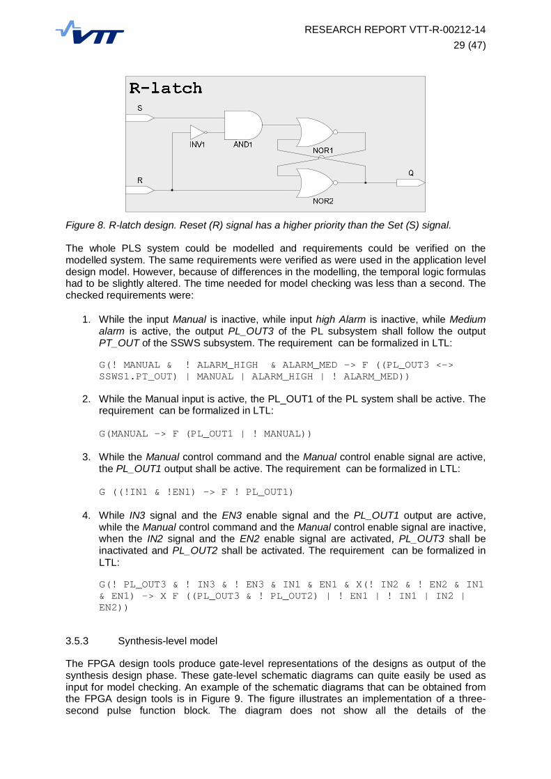
The flip-flops of the PLS system were implemented using R-latches, see Figure 8.These R-latches are composed using the fundamental logic blocks (inverters, ANDblocks, and NOR blocks). The implementation of the flip-flop is thus more detailedwhen compared to the application level design model. The model code for the R-latchis below:
MODULE R_LATCH(set, reset)VARINV1 : INV(reset);AND1 : AND(set, INV1.OUTPUT);NOR1 : NOR(AND1.OUTPUT, NOR2.OUTPUT);NOR2 : NOR(NOR1.OUTPUT, reset);DEFINEOUTPUT := NOR2.OUTPUT;ASSIGN
The timing used in the model differs from the timing of the application level designmodel. In the VHDL-level model, each individual function block takes one time pointto update its outputs based on the inputs. This means that it takes several time stepsfor a signal to travel through the whole PLS system. This is somewhat more realisticthan the synchronic implementation of the application level design model, in which asignal travels through the system instantly. As an example for this kind of modelling,see the model code for the AND function block:
MODULE AND(input1, input2)VAROUTPUT : boolean;DEFINEASSIGNinit(OUTPUT) := FALSE;next(OUTPUT):= input1 & input2;
The clock signal of the PLS system was not explicitly modelled. This is because ofthe discrete notion time used in the NuSMV tool. The discrete time structure can beseen as a model of the clock signal.
The delays of the PULSE function blocks were modelled so that there are 10 timesteps in a second (a three-second PULSE block takes 30 time steps). This modellingsolution is not totally realistic since the length of the pulse is in reality a lot longer thanthe time it takes for a signal to travel through a function block (1 time step). Someclock cycle abstraction is needed for feasibility.
RESEARCH REPORT VTT-R-00212-1429 (47)
Figure 8. R-latch design. Reset (R) signal has a higher priority than the Set (S) signal.
The whole PLS system could be modelled and requirements could be verified on themodelled system. The same requirements were verified as were used in the application leveldesign model. However, because of differences in the modelling, the temporal logic formulashad to be slightly altered. The time needed for model checking was less than a second. Thechecked requirements were:
1. While the input Manual is inactive, while input high Alarm is inactive, while Mediumalarm is active, the output PL_OUT3 of the PL subsystem shall follow the outputPT_OUT of the SSWS subsystem. The requirement can be formalized in LTL:
G(! MANUAL & ! ALARM_HIGH & ALARM_MED -> F ((PL_OUT3 <->SSWS1.PT_OUT) | MANUAL | ALARM_HIGH | ! ALARM_MED))
2. While the Manual input is active, the PL_OUT1 of the PL system shall be active. Therequirement can be formalized in LTL:
G(MANUAL -> F (PL_OUT1 | ! MANUAL))
3. While the Manual control command and the Manual control enable signal are active,the PL_OUT1 output shall be active. The requirement can be formalized in LTL:
G ((!IN1 & !EN1) -> F ! PL_OUT1)
4. While IN3 signal and the EN3 enable signal and the PL_OUT1 output are active,while the Manual control command and the Manual control enable signal are inactive,when the IN2 signal and the EN2 enable signal are activated, PL_OUT3 shall beinactivated and PL_OUT2 shall be activated. The requirement can be formalized inLTL:
G(! PL_OUT3 & ! IN3 & ! EN3 & IN1 & EN1 & X(! IN2 & ! EN2 & IN1& EN1) -> X F ((PL_OUT3 & ! PL_OUT2) | ! EN1 | ! IN1 | IN2 |EN2))
3.5.3 Synthesis-level model
The FPGA design tools produce gate-level representations of the designs as output of thesynthesis design phase. These gate-level schematic diagrams can quite easily be used asinput for model checking. An example of the schematic diagrams that can be obtained fromthe FPGA design tools is in Figure 9. The figure illustrates an implementation of a three-second pulse function block. The diagram does not show all the details of the
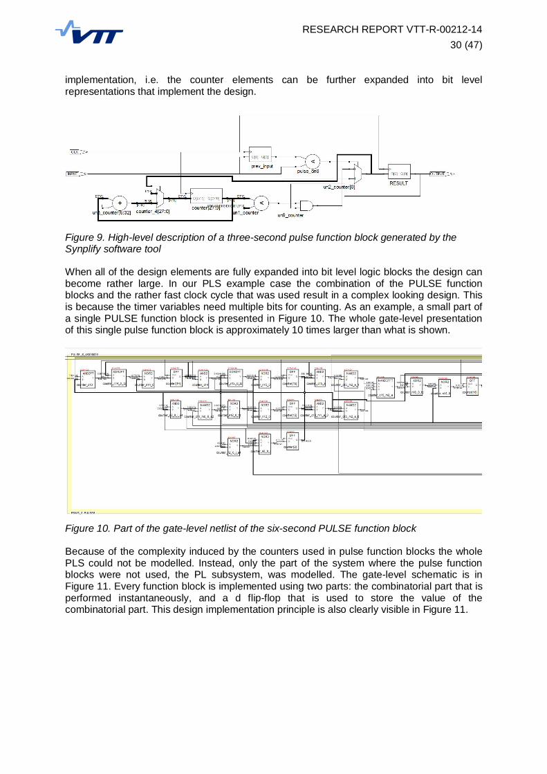
RESEARCH REPORT VTT-R-00212-1430 (47)
implementation, i.e. the counter elements can be further expanded into bit levelrepresentations that implement the design.
Figure 9. High-level description of a three-second pulse function block generated by theSynplify software tool
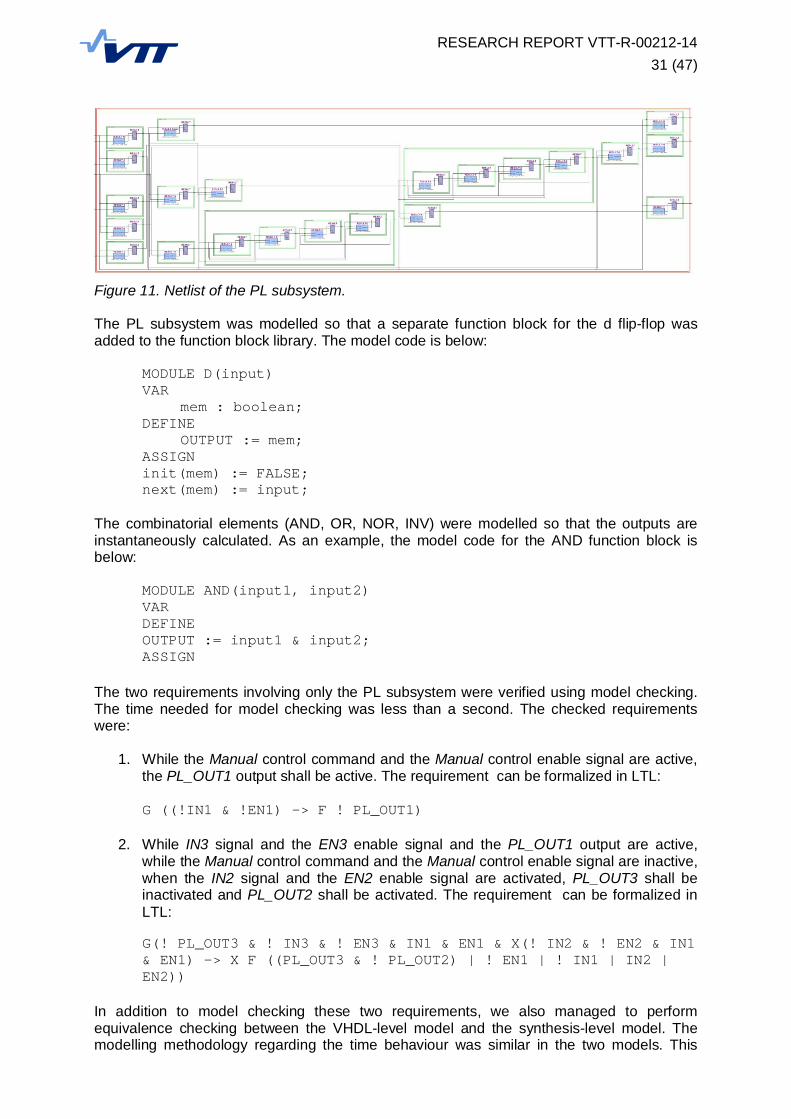
When all of the design elements are fully expanded into bit level logic blocks the design canbecome rather large. In our PLS example case the combination of the PULSE functionblocks and the rather fast clock cycle that was used result in a complex looking design. Thisis because the timer variables need multiple bits for counting. As an example, a small part ofa single PULSE function block is presented in Figure 10. The whole gate-level presentationof this single pulse function block is approximately 10 times larger than what is shown.
Figure 10. Part of the gate-level netlist of the six-second PULSE function block
Because of the complexity induced by the counters used in pulse function blocks the wholePLS could not be modelled. Instead, only the part of the system where the pulse functionblocks were not used, the PL subsystem, was modelled. The gate-level schematic is inFigure 11. Every function block is implemented using two parts: the combinatorial part that isperformed instantaneously, and a d flip-flop that is used to store the value of thecombinatorial part. This design implementation principle is also clearly visible in Figure 11.
RESEARCH REPORT VTT-R-00212-1431 (47)
Figure 11. Netlist of the PL subsystem.
The PL subsystem was modelled so that a separate function block for the d flip-flop wasadded to the function block library. The model code is below:
MODULE D(input)VAR
mem : boolean;DEFINE
OUTPUT := mem;ASSIGNinit(mem) := FALSE;next(mem) := input;
The combinatorial elements (AND, OR, NOR, INV) were modelled so that the outputs areinstantaneously calculated. As an example, the model code for the AND function block isbelow:
MODULE AND(input1, input2)VARDEFINEOUTPUT := input1 & input2;ASSIGN
The two requirements involving only the PL subsystem were verified using model checking.The time needed for model checking was less than a second. The checked requirementswere:
1. While the Manual control command and the Manual control enable signal are active,the PL_OUT1 output shall be active. The requirement can be formalized in LTL:
G ((!IN1 & !EN1) -> F ! PL_OUT1)
2. While IN3 signal and the EN3 enable signal and the PL_OUT1 output are active,while the Manual control command and the Manual control enable signal are inactive,when the IN2 signal and the EN2 enable signal are activated, PL_OUT3 shall beinactivated and PL_OUT2 shall be activated. The requirement can be formalized inLTL:
G(! PL_OUT3 & ! IN3 & ! EN3 & IN1 & EN1 & X(! IN2 & ! EN2 & IN1& EN1) -> X F ((PL_OUT3 & ! PL_OUT2) | ! EN1 | ! IN1 | IN2 |EN2))
In addition to model checking these two requirements, we also managed to performequivalence checking between the VHDL-level model and the synthesis-level model. Themodelling methodology regarding the time behaviour was similar in the two models. This

RESEARCH REPORT VTT-R-00212-1432 (47)
allowed us to verify that the outputs of the two models always correspond to each other if theinputs of the models are the same. We did this equivalence checking by creating a modelthat had the two models as separate modules. Then the same set of input variables wasconnected to both modules. It is then quite easy to verify that the outputs of the modulescorrespond to each other in all possible cases:
G (PL_VHDL.OUT1 <-> PL_SYNTHESIS.OUT1)G (PL_VHDL.OUT2 <-> PL_SYNTHESIS.OUT2)G (PL_VHDL.OUT3 <-> PL_SYNTHESIS.OUT3)
3.6 Discussion and conclusions
We created three models of the PLS system: the application level design model, the VHDL-level model, and the synthesis-level model based on a gate-level schematic diagram. Designdiagrams such as function block diagrams we have already modelled and verified in previouscase studies, see e.g. [Lahtinen et al., 2012]. In our experience, the model checking of thefunction block diagrams has been very useful and worthwhile.
In this case study, the VHDL-level model and the synthesis-level model were functionallyequivalent. Analysing VHDL can be beneficial if the language used in application design isnot well-defined. On the VHDL-level it is possible to see how the more complex functionblocks have been implemented. A model based on the actual implementation code morelikely corresponds to the actual system behaviour.
In this work we have created the VHDL-level model and the synthesis-level model manuallybased on VHDL code and schematic diagrams output by the FPGA design tools. This is notoptimal since it takes a fair amount of work and the manual modelling phase is alwayssuspect to errors. It would be much more useful if the VHDL code itself could be used formodel checking. Some tools for this purpose exist, for example, the CV tool by [Déharbe etal., 1998].
One of the main observations made during this work is that modelling the system on thegate-level can be very laborious when the system has counters that use large integervariables. These kinds of counters were in the case study system because the clock cycle ofthe FPGA device was on the megahertz scale while the time delays used in the designedsystem were on the scale of seconds. The counters lead to large implementations when theyare examined on the gate-level. It is also probable that if the design was precisely modelledon the gate-level, there would be problems in the property verification phase of modelchecking (state explosion and/or huge counter-example length). The problem could beavoided be using a longer clock cycle in the FPGA device, or by creating abstractions for thecounters.
In this work we did not use the low-level netlist output by the place and route design phase.On this level the placement of the used gates on the FPGA chip (chip planning) is also takeninto consideration. In practice, the placement of gates on the chip has influence on the time ittakes for a signal to travel from one gate to another. If we wanted to model the system onthis level, these time delays would have to be modelled as well. In all other aspects the low-level netlist produced in place and route corresponds to the synthesis-level netlist. In ourpreliminary experience it could be possible to create models that take the chip planning intoaccount but such modelling would probably be unpractical. In addition, for verifying suchmodels we would have to use some other model checking tool that is more capable foranalysing real-valued time delays. In all probability, using model checking for the mostdetailed design phase where the chip planning is taken in to account is not sensible,especially because there are tools designed specifically for analysing that the timings of thechip are adequate. Furthermore, there are tools used in FPGA design that check theequivalence of two consecutive design phases. These kinds of tools are probably moreuseful for verifying that the low-level phases have been performed correctly.
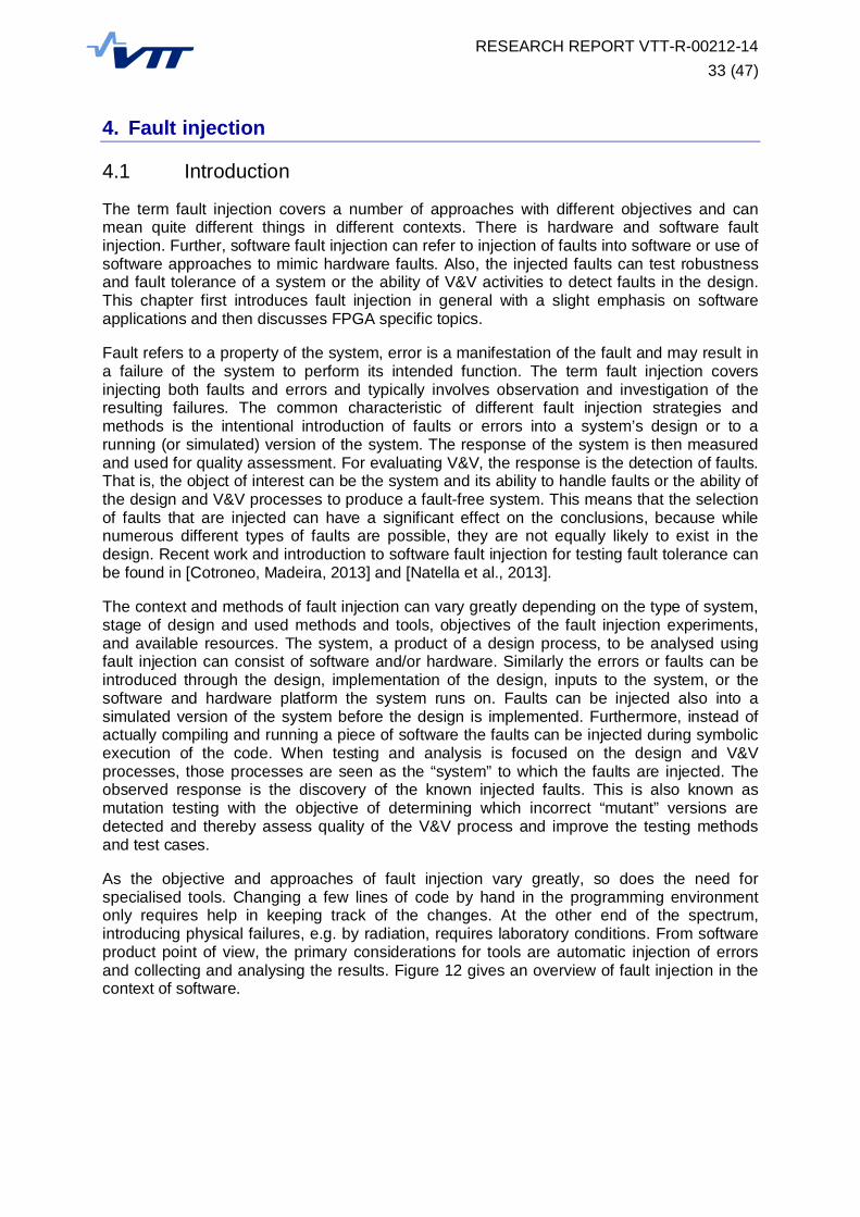
RESEARCH REPORT VTT-R-00212-1433 (47)
4. Fault injection
4.1 Introduction
The term fault injection covers a number of approaches with different objectives and canmean quite different things in different contexts. There is hardware and software faultinjection. Further, software fault injection can refer to injection of faults into software or use ofsoftware approaches to mimic hardware faults. Also, the injected faults can test robustnessand fault tolerance of a system or the ability of V&V activities to detect faults in the design.This chapter first introduces fault injection in general with a slight emphasis on softwareapplications and then discusses FPGA specific topics.
Fault refers to a property of the system, error is a manifestation of the fault and may result ina failure of the system to perform its intended function. The term fault injection coversinjecting both faults and errors and typically involves observation and investigation of theresulting failures. The common characteristic of different fault injection strategies andmethods is the intentional introduction of faults or errors into a system’s design or to arunning (or simulated) version of the system. The response of the system is then measuredand used for quality assessment. For evaluating V&V, the response is the detection of faults.That is, the object of interest can be the system and its ability to handle faults or the ability ofthe design and V&V processes to produce a fault-free system. This means that the selectionof faults that are injected can have a significant effect on the conclusions, because whilenumerous different types of faults are possible, they are not equally likely to exist in thedesign. Recent work and introduction to software fault injection for testing fault tolerance canbe found in [Cotroneo, Madeira, 2013] and [Natella et al., 2013].
The context and methods of fault injection can vary greatly depending on the type of system,stage of design and used methods and tools, objectives of the fault injection experiments,and available resources. The system, a product of a design process, to be analysed usingfault injection can consist of software and/or hardware. Similarly the errors or faults can beintroduced through the design, implementation of the design, inputs to the system, or thesoftware and hardware platform the system runs on. Faults can be injected also into asimulated version of the system before the design is implemented. Furthermore, instead ofactually compiling and running a piece of software the faults can be injected during symbolicexecution of the code. When testing and analysis is focused on the design and V&Vprocesses, those processes are seen as the “system” to which the faults are injected. Theobserved response is the discovery of the known injected faults. This is also known asmutation testing with the objective of determining which incorrect “mutant” versions aredetected and thereby assess quality of the V&V process and improve the testing methodsand test cases.
As the objective and approaches of fault injection vary greatly, so does the need forspecialised tools. Changing a few lines of code by hand in the programming environmentonly requires help in keeping track of the changes. At the other end of the spectrum,introducing physical failures, e.g. by radiation, requires laboratory conditions. From softwareproduct point of view, the primary considerations for tools are automatic injection of errorsand collecting and analysing the results. Figure 12 gives an overview of fault injection in thecontext of software.

RESEARCH REPORT VTT-R-00212-1434 (47)
Figure 12. Overview of fault injection approaches for software. Blue texts indicate methods offault injection and green texts observations made from the fault injection tests.
4.2 Objectives of fault injection
4.2.1 Evaluate the effectiveness of the design and V&V process
Though it may be impossible to verify that there are no faults in a design or identify existingfaults, the number of faults can be estimated using a known set of faults. The discovery offaults in a design is “simulated” using a set of intentionally introduced faults. A number ofknown faults are introduced into the software source code, HDL (Hardware DescriptionLanguage) code of an FPGA design, or the design in another format. For example, “a=a+1”can be changed to “a=a-1” or an incorrect variable is used in a function call. Normalverification activities are then performed and the fraction of the introduced errors that are notdiscovered is used as an estimate of what proportion of unknown actual errors remainundiscovered. The distribution of the types of errors injected should correspond to thedistribution of actual errors typically created by designers for the results to be meaningful.This testing of V&V effectiveness can also focus on a specific tool or method, such as astatic code analyser, however, automation of the testing and analysis procedures is neededfor efficiently repeating them for different fault sets.
Processor
….................Design...
.documents.….................Source.......Code....…..............
Errors according to aprofile typical to thesoftware in question
Radiation(heavy ions, EM)Power fluctuationTemperature
Executable
Memory
Automatic injectionduring compilation
…..........Input...Data..….........
Special (corner) casesIncorrect or inconsistent data
Fraction of injectedfaults discoveredduring V&V
Expected behaviourand response
Runtime faultdetection,recovery andtolerance
Runtimeinjection
…..........Output...Data..….........
RESEARCH REPORT VTT-R-00212-1435 (47)
4.2.2 Test error detection and fault recovery of the system
This is the common application of fault injection methods and is used for both design faultsand those resulting from hardware faults, incorrect inputs, and other runtime issues. Typicallysystems include functions which detect errors and try to recover from them during operation.These include, e.g., input validity checking, use of triple modular redundancy, and watchdogtimers. If an error is detected, corrective action can be taken to try to restore correct internalstate and normal operation of the system or drive the system to a safe mode. To test thesefunctions, faults and error states are artificially triggered by suitable manipulation of thedesign, inputs to the system, or manipulation of hardware (mechanical, electrical, radiation).Essentially, an error or fault is simulated and the response of the system is observed. Theerror can originate in another system represented by the inputs or be a software or hardwarefault of the system under testing. When manipulating the inputs, they can be designed totrigger a specific response from the system. This may be done through both the format of theinputs and their range of values. Faults injected into the design (software) of the system cansimulate design errors and allow evaluation of the system’s ability to detect internal errorsand recover from them. Additionally, some hardware faults can be emulated using software.Fault injection through hardware can simulate a failure of some component but also an errorin data caused, e.g., by a single event upset (SEU) in SRAM or the state of a flip-flop in anFPGA. SEU are electrical disturbances cause by ionizing radiation resulting in changes in thestate of the memory or signals.
4.2.3 Trigger functions that are inactive under normal operating conditions and allowwider test coverage of functionality
Some functions (segments of code in software or components on an FPGA) are onlyactivated under specific circumstances. These include the error detection and recoveryfunctions mentioned in the previous section but also functions used under uncommonoperating conditions. In addition to driving the system into a state in which the functions areexecuted, the conditions that trigger the function can be altered, e.g., by changing parametervalues controlling the threshold or simply changing the content of an “if”-statement. Thus, it isnot necessary to actually drive the system into the state which triggers the functions but, onthe other hand, the response might be incorrect as the state does not match the conditionsthe function is intended for.
4.2.4 Fault injection at early design phases
In some cases it is possible to perform fault injection early on before implementation of thedesign. A high abstraction level description of a system (“electronic system level” using e.g.System C or System Verilog) describes components and their interaction without the detailsof implementation. If the functionality can be simulated in an early design phase, the effect ofsome types of faults on the behaviour of the system can be tested. In particular errorpropagation between the components and faults in the communication protocols are potentialtargets.
4.3 Methods to inject faults
From the perspective of software based automation systems the program source code is anatural target for fault injection. A very similar approach is to manipulate the hardwaredescription language (HDL) code of hardware, e.g. FPGA, based systems. In addition to thesource code, the injection can also be done into a compiled form of the code (e.g. softwareobject code or hardware netlist). Using automated tools the engineer doesn’t have to actuallymake the changes to the code. The tools inject the faults during compile and even thegeneration and selection of faults to be injected can be automated.
RESEARCH REPORT VTT-R-00212-1436 (47)
The injection can also take place during runtime. The fault can be in the code but is onlyactivated by, e.g., a timer, interrupt trigger, execution entering some specific path, or amemory area being accessed. Direct manipulation of the program in memory while it isexecuting is also possible, thus the fault can be injected and removed during execution. Thiscan be done with a software layer between the application and the operating system. Theeffects the additional software layer may have on the performance, especially timingproperties, of the system needs to be carefully evaluated for real time systems. Alsospecialised hardware can be used to alter the program during runtime.
Fault injection through manipulation of the inputs of the system can be implemented usingaltered input files, direct manipulation of RAM, or using a simulated operating environment.Input files containing errors can implement many types of faults and error situations as thecontent can be manipulated freely. The runtime data in memory can be controlled with, forexample, a similar software layer as used for runtime injection of faults into the program’sfunctionality. This allows a further dimension compared to altered input files. A fault injectedduring execution can simulate also memory corruption or hardware failure in addition toexternal inputs to the system. A simulated operating environment can provide also ananalysis of chains of events and wider scope of consequences resulting from the fault as thesystem under investigation interacts with other systems. However, forcing a complexsimulation model into a specific state which is also physically consistent may be laborious.
Physical- or hardware injection can refer to causing physical errors or failures (hardwaremalfunction) in the system or using special hardware instrumentation to inject the desiredfaults (e.g. alter the signals between an FPGA and circuit board). Methods to cause physicalerrors and faults include the use of power surges, electromagnetic interference, and heavyion radiation. An even more concrete form of physical fault injection is the physical alterationof the system’s hardware. The objective can be to test how well the system can handle faultsin the form of hardware failures (detect, recover, reconfigure, tolerate). The faults injectedusing methods such as ion radiation or electromagnetic interference are not repeatable as itmay be impossible to know what actually happened inside the component, especially, if thefault is transient, i.e., not a permanent physical alteration but an incorrect signal or state inthe circuitry. Physical injection can also refer to using an equipment layer between theprocessor or memory and the board (i.e. injection not done within software). Also, testingpins (JTAG) of electronic components can be used for this purpose.
In addition to testing individual systems, communication between systems or subsystemscan be targeted for fault injection. Fundamentally this targets errors or inconsistencies in thedesign of the protocol or how different systems implement it. A classic example ofmiscommunication is the Ariane 5 crash where an error signal was interpreted as ameasurement and thus resulted in a control signal with a wildly incorrect value. One systemwas expecting an integer representing a measurement value but the other system sent aninteger that should have been recognized as indicator of error. In this particular exampleeven testing with predicted flight trajectory data would have exposed the problem withoutneed for fault injection. The approach of injecting errors to the communication betweensystems can be used for testing black box pieces of software (e.g. COTS libraries). Evenwithout access to the source code the propagation of the errors can be analysed as thesignals between the black boxes are observable.
4.4 Application of fault injection to V&V of FPGA based systems
FPGA based systems usually use a design life cycle similar to software development. Theresult, however, is a hardware component with physically hardwired functionality. There is nooperating system and all functions have dedicated hardware (transistors in the circuitry)instead of a central processor handling sequential instructions of several programs(operating system, hardware drivers, and applications). Still, the similarity between HDL andsoftware source code make many fault injection approaches similar between FPGAs and

RESEARCH REPORT VTT-R-00212-1437 (47)
software. It is not a recommended approach for safety related applications, but FPGAs canbe used to implement microprocessor cores and then run software, thus complicating theoverall design and combining need for V&V of both software and FPGA design.
The stages of design, see Figure 6 in Chapter 3, can all be targeted with some type of faultinjection testing. In an FPGA the memory and processing are implemented in the samedevice. The memory on the device holds the state data of the system (i.e. data beingprocessed) and configuration data (i.e. programmed functionality) of the device. This issimilar to a computer’s memory containing the program and its data but in an FPGA the datais not transferred back and forth between memory and processor. Also, whereas the memoryof a computer is fully accessible, the memory on an FPGA has limited accessibility. Readingthe entire state of the system or its configuration may be impossible, thus limiting thepossibility of tracking error propagation.
One aspect of interest is the tolerance of the FPGA to single event upsets. The configurationof the device, i.e. how the functionality is implemented and distributed onto the hardware,has an effect on SEU sensitivity. Hence, the same functionality can be implemented withdifferent tolerance to physical disturbances. The chosen technology (SRAM, flash, antifuse)of the FPGA also has a significant effect on SEU tolerance. Antifuse technology has theproperty that it is one-time configurable, and runtime changes, and thereby fault injection, toconfiguration are not possible. Also, from the point of view of device selection the faulttolerance of the configuration process should be considered. It should be possible to verifythat the configuration in the device is as intended. An approach using the extra computingresources on an FPGA to implement runtime fault injection is given in [Nazar, Carro, 2012]where unused areas of the device implement functions that create changes in theconfiguration memory.
The Figure 12 works well also for giving an overview of the use of fault injection in FPGAdesign V&V, if the source code is replaced with HDL code, compilation is replaced bysynthesis and place and route, executable program is replaced by configuration file, andinstead of separate memory and processor there is only the FPGA device. Certainly the toolsand details differ but the overall view is similar.
4.5 Tools
A number of tools are presented in [Natella et al., 2013], [Hsueh et al., 1997], and [Hissam etal., 2004]. Suitable tools depend on the chosen programming language, hardware choices,and objectives. Desirable properties of tools for fault injection are described in [Vinter et al.,2007]. The nature of the system and methods to inject faults affect heavily the achievability ofthese properties. The properties are listed here as a checklist of what to consider whenevaluating and selecting tools.
Reachability refers to the ability of the tool to access and inject faults to different partsof the target systemControllability in space means the accuracy of where the fault is injected whilecontrollability in time means the accuracy of when then fault is injectedRepeatability allows an experiment to be repeated with consistent resultsReproducibility means that the statistical properties of a set of tests can bereproducedIntrusiveness refers to the amount of unwanted side effects the fault injection has onthe system behaviour and performance and can be divided into intrusiveness in timeand spaceFlexibility allows the easy modification of the “where” and “when” of faults that areinjected in the tests

RESEARCH REPORT VTT-R-00212-1438 (47)
Effectiveness is the ability to activate fault handling mechanisms in the systemEfficiency refers to the time and effort required to run the testsObservability means the ease and coverage of observing and measuring the effectthe faults have on the system
RESEARCH REPORT VTT-R-00212-1439 (47)
References
Beer, I., Ben-David, S., Eisner, C., Landver, A. RuleBase: an Industry-Oriented FormalVerification Tool. Proceedings of 33rd Design Automation Conference (DAC 96). pp.655-660, Las Vegas, NV, 3-7 Jun, 1996.
Borrione, D.D., Pierre, L.V., Salem, A.M. Formal Verification of VHDL Descriptions in thePrevail Environment. IEEE Design & Test of Computers. Vol. 9. Number 2, pp. 42-56,1992.
Burch, J., Clarke, E., McMillan, K., Dill, D., Hwang, L. Symbolic model checking: 10^20 statesand beyond. Information and Computation 1992;98(2) pp. 142–70, 1992.
Cavada, R., Cimatti, A., Jochim, C.A., Keighren, G., Olivetti, E., Pistore, M., Roveri, M.,Tchaltsev, A.: NuSMV 2.5 User Manual. FBK-irst., 2010.
Cotroneo, D., Madeira, H. “Introduction to Software Fault Injection”, in Cotroneo, D. (ed),Innovative Technologies for Dependable OTS-Based Critical Systems, Springer,2013.
Daumas, F., Druilhe, A., Thuy, N. Justification Framework for the Formal Verification of aMicroprocessor FPGA Emulator Application to the MC6800 p. 5th FPGA IAEAWorkshop, Beijing, 2012.
Déharbe, D, Shankar, S., Clarke, E.M. Model Checking VHDL with CV. Proceedings of theSecond International Conference on Formal Methods in Computer-Aided Design.FMCAD '98. 508-514. Springer-Verlag, London, UK, 1998.
Electric Power Research Institute. EPRI TR-1019181: Guidelines on the Use of FieldProgrammable Gate Arrays (FPGAs) in Nuclear Power Plant I&C Systems. EPRI,Palo Alto, California, USA, 2009.
Fix, L. Fifteen years of formal property verification in Intel. 25 Years of model checking.Lecture Notes in Computer Science 2008;5000, pp. 139–44, 2008.
Hissam, Z., Ayoubi, R., Velazco, R. A Survey on Fault Injection Techniques. TheInternational Arab Journal of Information Technology, Vol. 1, No. 2, pp. 171-186, July2004.
Hsueh, C-H, Tsai, T.K., Iyer, R.K. Fault Injection Techniques and Tools. Computer, Vol. 30,No. 4, pp. 75-82, April 1997.
IEC 61131-3. International Standard for Programmable Controllers – Part 3: ProgrammingLanguages, IEC, 1993.
IEC/ISO/IEEE 29119-4. Software and systems engineering – Software testing – Part 4: Testtechniques, International standard, 2013.
Jee, E., Jeon, S., Bang, H., Cha, S. Testing of Timer Function Blocks in FBD. XIII ASIAPACIFIC SOFTWARE ENGINEERING CONFERENCE (APSEC'06). 2006.
Jee, E., Yoo, J., Cha, S., Bae, D. A data flow-based structural testing technique for FBDprograms, Information and Software Technology, Volume 51, Issue 7, July 2009,Pages 1131-1139, ISSN 0950-5849, 10.1016/j.infsof.2009.01.003.

RESEARCH REPORT VTT-R-00212-1440 (47)
Jee, E., Kim, S., Cha S., Lee, I., Automated Test Coverage Measurement for ReactorProtection System Software implemented in Function Block Diagram, SAFECOMP2010. The 29th International Conference on Computer Safety, Reliability andSecurity. September 14 - 17 2010. Vienna, Austria.
Lahtinen, J., Valkonen, J., Björkman, K., Frits, J., Niemelä, I., Heljanko, K. Model-checking ofsafety-critical software in the nuclear engineering domain. Reliability Engineering andSystem Safety 105. pp. 104-113, Elsevier, 2012.
Lötjönen, L. FPGA Implementation of the Stepwise Shutdown System. VTT Research report.VTT-R-06053-12. Espoo, Finland. 2012.
Lötjönen, L. Field-Programmable Gate Arrays in Nuclear Power Plant Safety Automation.Master’s Thesis. Aalto University. 2013. Available online:https://aaltodoc.aalto.fi/handle/123456789/10921
Lötjönen, L., Ranta, J., Lahtinen, J., Valkonen, J., Holmberg, J-E. 2013. Use of Field-Programmable Gate Arrays in Nuclear I&C Safety Systems – Case StepwiseShutdown System. Automaatio XX. Helsinki, Finland.
Natella, R., Cotroneo, D., Duraes, J.A., Madeira, H.S. On Fault Representativeness ofSoftware Fault Injection. IEEE Transactions on Software Engineering, Vol. 39, No. 1,January 2013.
Nazar, G.L., Carro, L. Fast Single-FPGA Fault Injection Platform. 2012 IEEE InternationalSymposium on Defect and Fault Tolerance in VLSI and Nanotechnology Systems(DFT), Austin, Texas, U.S.A., October 3 - 5, 2012.
Pakonen, A., Mätäsniemi, T., Lahtinen, J., Karhela, T., A Toolset for Model Checking of PLCSoftware, 18th IEEE International Conference on Emerging Technologies andFactory Automation, ETFA2013, 10-13 September 2013, Cagliari, Italy, Proceedings.IEEE, 2013.
Pyykkö, P. Dynamic testing of safety-critical software, M.Sc. thesis, Helsinki University ofTechnology, Espoo, Finland, 2010.
Sheeran, M., Singh, S., Stålmarck, G. Checking Safety Properties Using Induction and aSAT-Solver. W.A. Hunt, Jr. and S.D. Johnson (Eds.): FMCAD 2000, LNCS 1954, pp.108-125, 2000.
Shin, D., Jee, E., Bae, D-H. Empirical Evaluation on FBD Model-Based Test CoverageCriteria Using Mutation Analysis, R.B. France et al. (Eds.): MODELS 2012, LNCS7590, pp. 465–479, 2012.
Simpson, P. FPGA Design – Best Practices for Team-based Design. ISBN 978-1-4419-6338-3. Springer, New York, USA, 2010.
Smith, G, FPGAs 101, Newnes, Boston, 2010, http://dx.doi.org/10.1016/B978-1-85617-706-1.00004-7.
USNRC. Software Unit Testing for Digital Computer Software Used in Safety Systems ofNuclear Power Plants, Regulatory Guide 1.171, September 1997.
USNRC. Review Guidelines for Field-Programmable Gate Arrays in Nuclear Power PlantSafety Systems. U.S. NRC, NUREG/CR-7006, (ORNL/TM-2009/20), 2010. Availableat: http://www.nrc.gov/reading-rm/doc-collections/nuregs/contract/cr7006 (accessed:7 November, 2013).

RESEARCH REPORT VTT-R-00212-1441 (47)
Vinter, J., Bromander, L., Raistrick, P., Edler, H. FISCADE - A Fault Injection Tool forSCADE Models. Automotive Electronics, 2007 3rd Institution of Engineering andTechnology Conference on. The University of Warwick, Coventry, UK, June 28 – 29,2007.
Wasaki, K., Iwasaki, N. Development of a Meta Description Language for Software/HardwareCooperative Design and Verification for Model-Checking Systems. InternationalJournal of Electrical and Electronics Engineering 3:4, 2009.
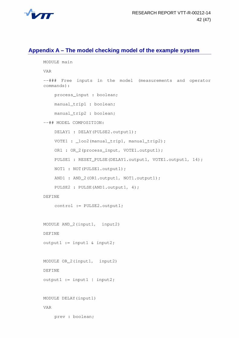
RESEARCH REPORT VTT-R-00212-1442 (47)
Appendix A – The model checking model of the example system
MODULE main
VAR
--### Free inputs in the model (measurements and operatorcommands):
process_input : boolean;
manual_trip1 : boolean;
manual_trip2 : boolean;
--## MODEL COMPOSITION:
DELAY1 : DELAY(PULSE2.output1);
VOTE1 : _1oo2(manual_trip1, manual_trip2);
OR1 : OR_2(process_input, VOTE1.output1);
PULSE1 : RESET_PULSE(DELAY1.output1, VOTE1.output1, 14);
NOT1 : NOT(PULSE1.output1);
AND1 : AND_2(OR1.output1, NOT1.output1);
PULSE2 : PULSE(AND1.output1, 4);
DEFINE
control := PULSE2.output1;
MODULE AND_2(input1, input2)
DEFINE
output1 := input1 & input2;
MODULE OR_2(input1, input2)
DEFINE
output1 := input1 | input2;
MODULE DELAY(input1)
VAR
prev : boolean;
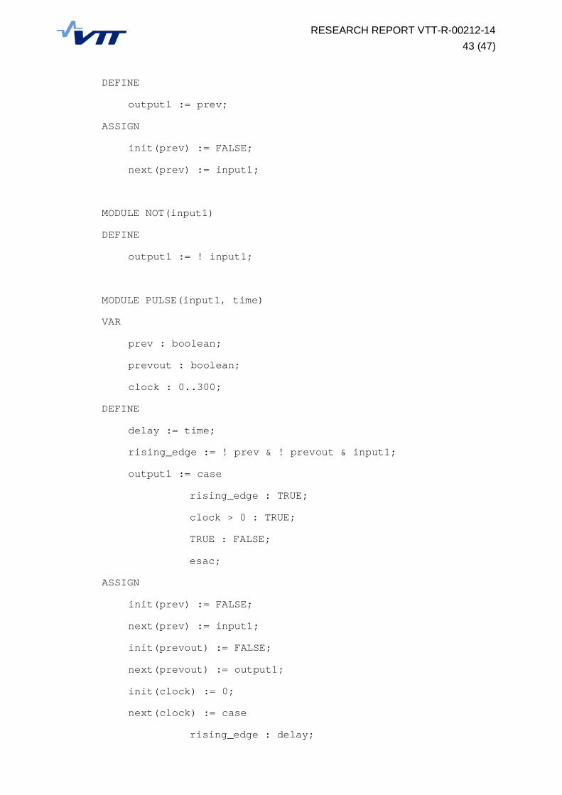
RESEARCH REPORT VTT-R-00212-1443 (47)
DEFINE
output1 := prev;
ASSIGN
init(prev) := FALSE;
next(prev) := input1;
MODULE NOT(input1)
DEFINE
output1 := ! input1;
MODULE PULSE(input1, time)
VAR
prev : boolean;
prevout : boolean;
clock : 0..300;
DEFINE
delay := time;
rising_edge := ! prev & ! prevout & input1;
output1 := case
rising_edge : TRUE;
clock > 0 : TRUE;
TRUE : FALSE;
esac;
ASSIGN
init(prev) := FALSE;
next(prev) := input1;
init(prevout) := FALSE;
next(prevout) := output1;
init(clock) := 0;
next(clock) := case
rising_edge : delay;
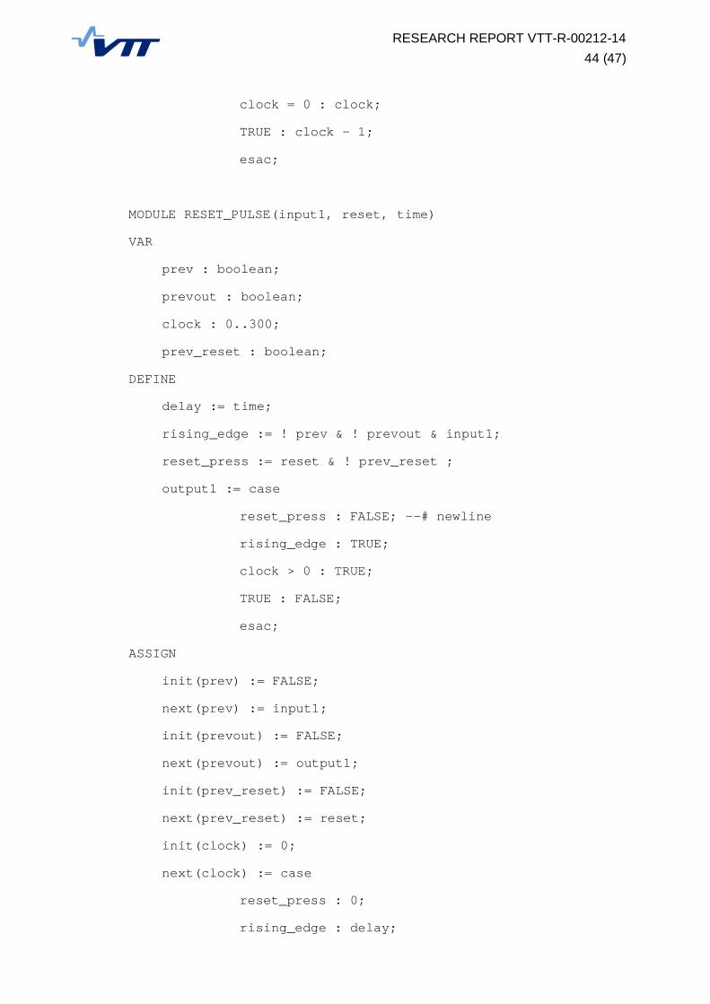
RESEARCH REPORT VTT-R-00212-1444 (47)
clock = 0 : clock;
TRUE : clock - 1;
esac;
MODULE RESET_PULSE(input1, reset, time)
VAR
prev : boolean;
prevout : boolean;
clock : 0..300;
prev_reset : boolean;
DEFINE
delay := time;
rising_edge := ! prev & ! prevout & input1;
reset_press := reset & ! prev_reset ;
output1 := case
reset_press : FALSE; --# newline
rising_edge : TRUE;
clock > 0 : TRUE;
TRUE : FALSE;
esac;
ASSIGN
init(prev) := FALSE;
next(prev) := input1;
init(prevout) := FALSE;
next(prevout) := output1;
init(prev_reset) := FALSE;
next(prev_reset) := reset;
init(clock) := 0;
next(clock) := case
reset_press : 0;
rising_edge : delay;

RESEARCH REPORT VTT-R-00212-1445 (47)
clock = 0 : clock;
TRUE : clock - 1;
esac;
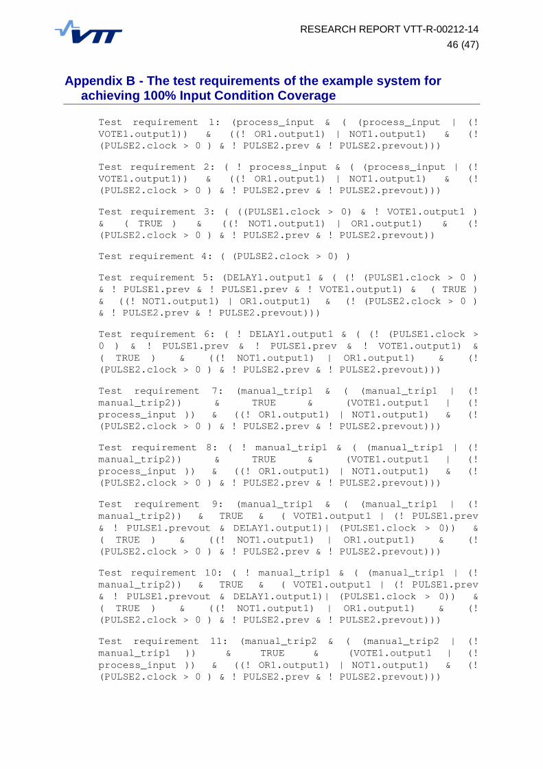
RESEARCH REPORT VTT-R-00212-1446 (47)
Appendix B - The test requirements of the example system forachieving 100% Input Condition Coverage
Test requirement 1: (process_input & ( (process_input | (!VOTE1.output1)) & ((! OR1.output1) | NOT1.output1) & (!(PULSE2.clock > 0 ) & ! PULSE2.prev & ! PULSE2.prevout)))
Test requirement 2: ( ! process_input & ( (process_input | (!VOTE1.output1)) & ((! OR1.output1) | NOT1.output1) & (!(PULSE2.clock > 0 ) & ! PULSE2.prev & ! PULSE2.prevout)))
Test requirement 3: ( ((PULSE1.clock > 0) & ! VOTE1.output1 )& ( TRUE ) & ((! NOT1.output1) | OR1.output1) & (!(PULSE2.clock > 0 ) & ! PULSE2.prev & ! PULSE2.prevout))
Test requirement 4: ( (PULSE2.clock > 0) )
Test requirement 5: (DELAY1.output1 & ( (! (PULSE1.clock > 0 )& ! PULSE1.prev & ! PULSE1.prev & ! VOTE1.output1) & ( TRUE )& ((! NOT1.output1) | OR1.output1) & (! (PULSE2.clock > 0 )& ! PULSE2.prev & ! PULSE2.prevout)))
Test requirement 6: ( ! DELAY1.output1 & ( (! (PULSE1.clock >0 ) & ! PULSE1.prev & ! PULSE1.prev & ! VOTE1.output1) &( TRUE ) & ((! NOT1.output1) | OR1.output1) & (!(PULSE2.clock > 0 ) & ! PULSE2.prev & ! PULSE2.prevout)))
Test requirement 7: (manual_trip1 & ( (manual_trip1 | (!manual_trip2)) & TRUE & (VOTE1.output1 | (!process_input )) & ((! OR1.output1) | NOT1.output1) & (!(PULSE2.clock > 0 ) & ! PULSE2.prev & ! PULSE2.prevout)))
Test requirement 8: ( ! manual_trip1 & ( (manual_trip1 | (!manual_trip2)) & TRUE & (VOTE1.output1 | (!process_input )) & ((! OR1.output1) | NOT1.output1) & (!(PULSE2.clock > 0 ) & ! PULSE2.prev & ! PULSE2.prevout)))
Test requirement 9: (manual_trip1 & ( (manual_trip1 | (!manual_trip2)) & TRUE & ( VOTE1.output1 | (! PULSE1.prev& ! PULSE1.prevout & DELAY1.output1)| (PULSE1.clock > 0)) &( TRUE ) & ((! NOT1.output1) | OR1.output1) & (!(PULSE2.clock > 0 ) & ! PULSE2.prev & ! PULSE2.prevout)))
Test requirement 10: ( ! manual_trip1 & ( (manual_trip1 | (!manual_trip2)) & TRUE & ( VOTE1.output1 | (! PULSE1.prev& ! PULSE1.prevout & DELAY1.output1)| (PULSE1.clock > 0)) &( TRUE ) & ((! NOT1.output1) | OR1.output1) & (!(PULSE2.clock > 0 ) & ! PULSE2.prev & ! PULSE2.prevout)))
Test requirement 11: (manual_trip2 & ( (manual_trip2 | (!manual_trip1 )) & TRUE & (VOTE1.output1 | (!process_input )) & ((! OR1.output1) | NOT1.output1) & (!(PULSE2.clock > 0 ) & ! PULSE2.prev & ! PULSE2.prevout)))

RESEARCH REPORT VTT-R-00212-1447 (47)
Test requirement 12: ( ! manual_trip2 & ( (manual_trip2 | (!manual_trip1 )) & TRUE & (VOTE1.output1 | (!process_input )) & ((! OR1.output1) | NOT1.output1) & (!(PULSE2.clock > 0 ) & ! PULSE2.prev & ! PULSE2.prevout)))
Test requirement 13: (manual_trip2 & ( (manual_trip2 | (!manual_trip1 )) & TRUE & ( VOTE1.output1 | (! PULSE1.prev& ! PULSE1.prevout & DELAY1.output1)| (PULSE1.clock > 0)) &( TRUE ) & ((! NOT1.output1) | OR1.output1) & (!(PULSE2.clock > 0 ) & ! PULSE2.prev & ! PULSE2.prevout)))
Test requirement 14: ( ! manual_trip2 & ( (manual_trip2 | (!manual_trip1 )) & TRUE & ( VOTE1.output1 | (! PULSE1.prev& ! PULSE1.prevout & DELAY1.output1)| (PULSE1.clock > 0)) &( TRUE ) & ((! NOT1.output1) | OR1.output1) & (!(PULSE2.clock > 0 ) & ! PULSE2.prev & ! PULSE2.prevout)))