CORRUGATED STEEL STRUCTURES UltraCor®
8
UltraCor® CORRUGATED STEEL STRUCTURES THE NEWEST GENERATION OF FLEXIBLE STRUCTURES
Transcript of CORRUGATED STEEL STRUCTURES UltraCor®

UltraCor®CORRUGATED STEEL STRUCTURES
THE NEWEST GENERATION OF FLEXIBLE STRUCTURES

Fig. 1. Wave profile of UC plate
Fot. 1. Wave height comparison in the structures
UltraCor®
SuperCor®
MultiPlate MP200
UltraCor® structures have many advantages over traditional bridge solutions:
● larger structure end area
● larger bearing of the structure
● higher range of cover depth
● lower costs of transportation
● reduction in total time and cost of building a bridge
● fast and easy assembly
Product features: ● the highest structural strength among the buried flexible steel structure
in the world
● large range of shapes and sizes
● easy and short installation time
● spans of 30 m and greater
3www.viacon.pl2 www.viacon.pl
UltraCor® CORRUGATED STEEL STRUCTURES CORRUGATED STEEL STRUCTURES UltraCor®
UltraCor® structures are the new generation of flexible structures made of galvanized corrugated steel plates. As the world’s deepest corrugation profile, UltraCor® combines all the advantages of lightweight construction with previously unheard-of strength and durability to create the largest corrugated steel structures in the world today.
UltraCor® structures are designed for all road and railway live load classes as well as under the load of special vehicles.
Introduction
Corrugation:
UltraCor® versatile structures are used for roads, railways and industrial applications as well as for reinforcement and reconstruction of existing structures such as:
● bridges
● overpasses
● tunnels
● culverts
● underpasses
● pedestrian tunnels
● ecological crossings
● hangars
● shelters
● underground storages
The UltraCor® corrugation profile is 500 x 237 mm.
Approvals and Certificates: ● CE Certificate according to norm EN 1090-1.
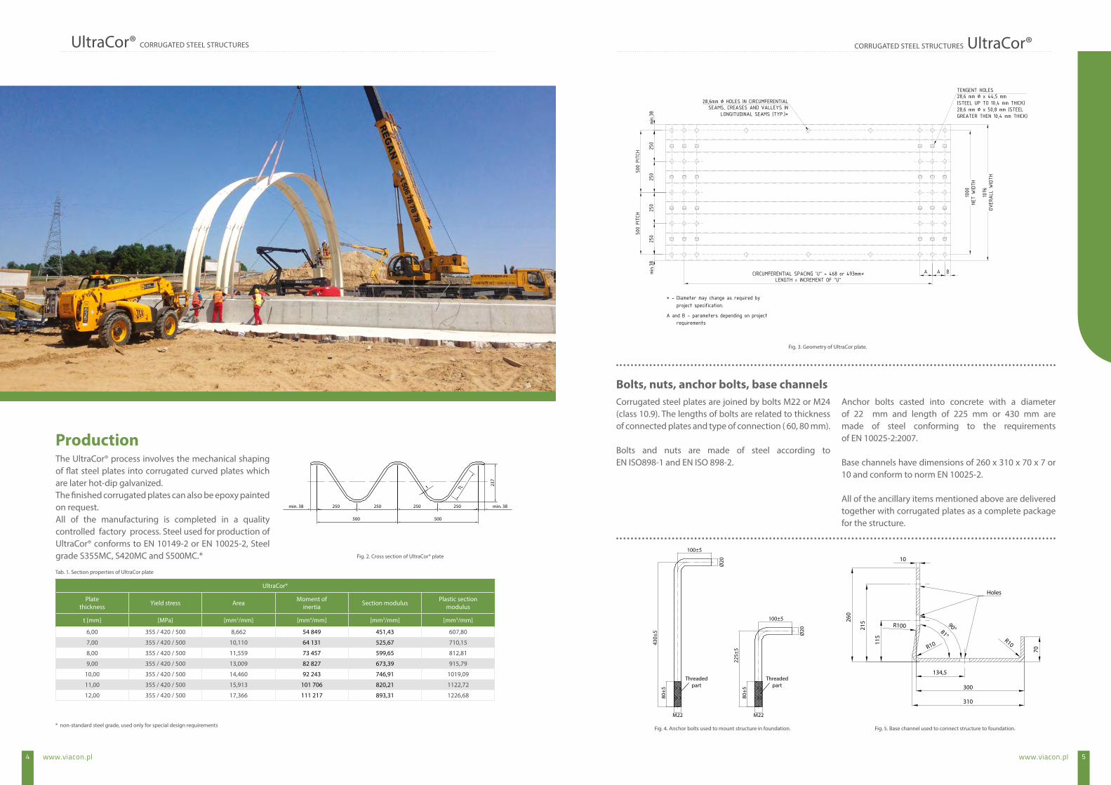
Fig. 2. Cross section of UltraCor® plate
5www.viacon.pl4 www.viacon.pl
UltraCor® CORRUGATED STEEL STRUCTURES CORRUGATED STEEL STRUCTURES UltraCor®
Tab. 1. Section properties of UltraCor plate
* non-standard steel grade, used only for special design requirements
UltraCor®
Plate thickness Yield stress Area Moment of
inertia Section modulus Plastic sectionmodulus
t [mm] [MPa] [mm2/mm] [mm4/mm] [mm3/mm] [mm3/mm]
6,00 355 / 420 / 500 8,662 54 849 451,43 607,80
7,00 355 / 420 / 500 10,110 64 131 525,67 710,15
8,00 355 / 420 / 500 11,559 73 457 599,65 812,81
9,00 355 / 420 / 500 13,009 82 827 673,39 915,79
10,00 355 / 420 / 500 14,460 92 243 746,91 1019,09
11,00 355 / 420 / 500 15,913 101 706 820,21 1122,72
12,00 355 / 420 / 500 17,366 111 217 893,31 1226,68
The UltraCor® process involves the mechanical shaping of flat steel plates into corrugated curved plates which are later hot-dip galvanized.The finished corrugated plates can also be epoxy painted on request.All of the manufacturing is completed in a quality controlled factory process. Steel used for production of UltraCor® conforms to EN 10149-2 or EN 10025-2, Steel grade S355MC, S420MC and S500MC.*
Production
Fig. 4. Anchor bolts used to mount structure in foundation.
Corrugated steel plates are joined by bolts M22 or M24 (class 10.9). The lengths of bolts are related to thickness of connected plates and type of connection ( 60, 80 mm).
Bolts and nuts are made of steel according to EN ISO898-1 and EN ISO 898-2.
Anchor bolts casted into concrete with a diameter of 22 mm and length of 225 mm or 430 mm are made of steel conforming to the requirements of EN 10025-2:2007.
Base channels have dimensions of 260 x 310 x 70 x 7 or 10 and conform to norm EN 10025-2.
All of the ancillary items mentioned above are delivered together with corrugated plates as a complete package for the structure.
Bolts, nuts, anchor bolts, base channels
Fig. 5. Base channel used to connect structure to foundation.
Fig. 3. Geometry of UltraCor plate.
Holes
10
R100
134,5
300
115
70
21526
0
310
R10R10
90°81°
Threadedpart
Threadedpart
M22M22
80±5
80±5
225±
5
430±
5
100±5
Ø20
Ø20
100±5

7www.viacon.pl6 www.viacon.pl
UltraCor® CORRUGATED STEEL STRUCTURES CORRUGATED STEEL STRUCTURES UltraCor®
Coatings applied by immersion including hot-dip galvanizing provide a durable method of corrosion protection to steel surfaces. The protection is particularly effective due to the lasting bond between the galvanizing coating and the steel surface, thereby providing extended service life. The zinc coating layer on UltraCor® structures are according to PN-EN ISO 1461 (table 2).
In order to extend the durability of UltraCor® structures, particularly in aggressive environments, additional corrosion protection can be provided by applying epoxy paint.
The protection of structures both by hot-dip galvanizing and epoxy paint creates the ViaCoat system conforming to PN-EN ISO 12944-5. Surfaces exposed to UV radiation are also coated with a polyurethane paint layer in order to prevent discoloration.
Corrosion protection
The design process of an UltraCor® structure constists of the following steps:
● design of the UltraCor® structure (including assembly)
● design of engineered backfilling procedure
● design of the foundations
● design of inlet, outlet and other associated fittings and elements
UltraCor® are designed with use of one of the following methods:
● Swedish Design Method, developed by Prof. Sundquist and Prof.
Petterson,
● CHBDC - Canadian Highways Bridge Design Code,
● AASHTO LRFD Bridge Design Specifications,
● finite element method (FEM) in complex cases.
Design
Structural analysis
Characteristics
Requirements acc. PN-EN ISO 1461
Minimal local zinccoating thickness
[µm]
Minimal averagezinc coating thickness
[µm]
Steel plate:>6 mm
>3 mm and ≤ 6 mm7055
8570
Bolts, nuts, anchor bolts 40 50
Base channel 70 85
Tab. 2. Zinc layer
Definition of the cover depth for road structures Vertical distance between top of a steel structure main barrel and top of the pavement including the pavement layer.
Definition of the cover depth for rail structuresVertical distance between top of a steel structure main barrel and bottom of railway sleeper.Lower cover depth is permissible when appropriate static calculations are conducted.In cases where construction traffic is travelling over a structure, the cover depth must be checked by ViaCon’s Technical Department.
Minimum cover depth also depends on the thickness of the pavement layer (Gn) and should not be less than:
H = Gn + 0,15 [m]
Lover cover depth is permissible when appropriate static calculations are conducted. Maximum depth of a cover is always designed individually.
For high cover depth load reduction techniques are available.
Tab. 3. Cover depth
Cover depth
Type of construction Min cover depth
Arched construction – low profiled H = 1/12 × B [m]

9www.viacon.pl8 www.viacon.pl
UltraCor® CORRUGATED STEEL STRUCTURES CORRUGATED STEEL STRUCTURES UltraCor®
Fig. 6. End finishes of UltraCor®
The base length of UltraCor® structures should conform to the following formula:
Ld = 38 + n × 1000 + 38 [mm]
where n – number of full rings alongside length
Top length of a structure varies depending on each jobsites constraints (considering inlets and outlets).
Geometry of a structure in longitudinal direction
x x2
x1
For multiple structure installations, the smallest clear spacing between adjacent structures should be sufficient for the placement and compaction of soil. The minimum spacing requirement depends on the shape and size of structures.
All details are described in the Technical Data Sheet provided by ViaCon’s Technical Department.
Multiple installation
Special consideration is required for skew angles smaller than 55 degrees. Concrete collars and/or reinforced soil can be applied to the inlet and outlet zones.
Please contact ViaCon’s Technical Department for advice.
Skew angels
Fig. 7. Skewed structure
Closed shaped UltraCor® structures (round, elliptical, pipe-arch) are placed on soil bedding as follows:
● minimum thickness of soil bedding should be 60 cm
● the top surface portion of the bedding should be shaped to fit to the
bottom plates of a structure
● particular care should be exercised in compacting soil under the
hauches
● top 25 cm layer of the bedding should be relatively loose material
UltraCor® structures with open shapes (arches, boxes) are placed on concrete footings.
Connection of the structure to the concrete footings is completed by using anchor bolts, taking the following into account:
● anchor bolts for concrete foundations are to be installed
in the concrete footings prior to delivery of a UltraCor® structure
● anchor bolts should not stick out from the top of the footing more
than 50 mm
● placing of anchor bolts should conform to the assembly drawing;
the allowable tolerance is ±3 mm in longitudinal direction and ±2 mm
in the transverse direction
● to minimize a risk of mistake, the location of each anchor should
always be measured from the starting point (first anchor)
● parallel placement of anchor bolts on each footing and perpendicular
placement of each pair of anchor bolts for individual rings are of great
importance; the better the accuracy, the easier the assembly
of the structure
Foundation
Fig. 8. Connection of UltraCor® structure with flexible footing Fig. 9. Connection of UltraCor® structure with concrete footing

In order to protect structures against water infiltrating through the backfill protective measures may be applied. Typically a layer of 1.0 mm thick HDPE geomembrane enclosed by two layers of protective non-woven geotextile (nominally 500g/m2) may be placed over steel structures. For some overpasses this infiltration protection has been provided using two layers of bentonite mat (geosynthetic clay liner).
Exceptions to the above are possible after consultation with ViaCon‘s Technical Department. Placing the membrane directly on the structures is allowed provided that protection layers are applied.
Please use the ViaCon Catalogue of Production Standard Solutions and Details for more details.
Protection against water ingress
Fig 10. Scheme of rainwater protection
Slopes may be finished by paving with locally available stones, blocks, etc. If gabion mattresses are used, additional waterproofing should be considered. Please contact ViaCon’s Technical Department for advice.
For vertically cut structures, as an alternative to reinforced concrete headwalls, MSE (reinforced soil) walls may be applied using either concrete blocks, panels or gabions.
If required, the ground around the UltraCor® construction can easily be reinforced during the backfilling process with geosynthetics.
End treatment (inlet/outlet) ● gravel, sand-gravel mix, well graded aggregates and crushed stone
can be used as bedding and backfill material
● aggregate grain size depends on size of the corrugation profile;
for 500x237 mm corrugations the max recommended aggregate
particle size is 120 mm
● aggregate particle size should be 0-120 mm, uniformity coefficient Cu
≥ 4,0 , curvature coefficient 1 ≤ Cc ≤ 3 and permeability k10>6 m/24
hours
● the use of cohesive soil, organic soil and any frozen soils is not
acceptable
● backfill material should be placed arround the structure in
uncompacted layers maximum 30 cm thick and then compacted
● the backfill should be placed on both sides of the structure at the
same time or alternating from one side of the structure to the other
side. No more than one layer (30 cm) difference in elevation is
permitted from one side to the other. Each layer must be compacted
to the specified compaction index before adding the next layer
● backfill material adjacent to the structure should be compacted to
minimum 95% of normal
Proctor density and to 98% of normal
Proctor density - in the remaining area unless otherwise noted
Deviation from these principles requires consultation with the ViaCon Technical Department.
Bedding and backfill
11www.viacon.pl10 www.viacon.pl
UltraCor® CORRUGATED STEEL STRUCTURES CORRUGATED STEEL STRUCTURES UltraCor®
13www.viacon.pl12 www.viacon.pl
UltraCor® CORRUGATED STEEL STRUCTURES CORRUGATED STEEL STRUCTURES UltraCor®
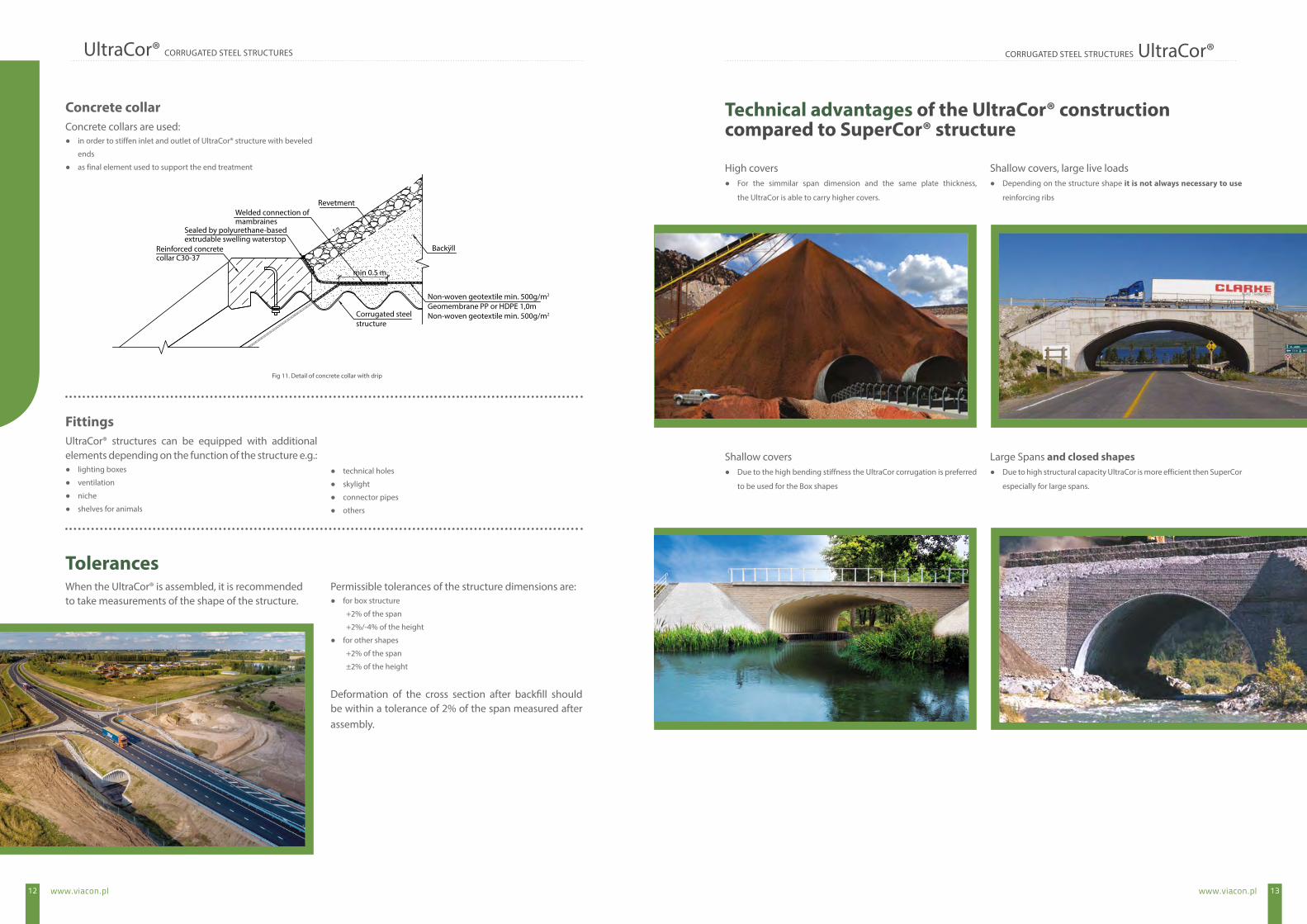
Concrete collars are used: ● in order to stiffen inlet and outlet of UltraCor® structure with beveled
ends
● as final element used to support the end treatment
UltraCor® structures can be equipped with additional elements depending on the function of the structure e.g.:
● lighting boxes
● ventilation
● niche
● shelves for animals
● technical holes
● skylight
● connector pipes
● others
High covers ● For the simmilar span dimension and the same plate thickness,
the UltraCor is able to carry higher covers.
Shallow covers, large live loads ● Depending on the structure shape it is not always necessary to use
reinforcing ribs
Shallow covers ● Due to the high bending stiffness the UltraCor corrugation is preferred
to be used for the Box shapes
Large Spans and closed shapes ● Due to high structural capacity UltraCor is more efficient then SuperCor
especially for large spans.
Concrete collar
Fittings
When the UltraCor® is assembled, it is recommended to take measurements of the shape of the structure.
Permissible tolerances of the structure dimensions are: ● for box structure
+2% of the span
+2%/-4% of the height
● for other shapes
+2% of the span
±2% of the height
Deformation of the cross section after backfill should be within a tolerance of 2% of the span measured after assembly.
Tolerances
Technical advantages of the UltraCor® construction compared to SuperCor® structure
Revetment
min 0.5 m
Backÿll
Corrugated steelstructure
Non-woven geotextile min. 500g/m2
Geomembrane PP or HDPE 1,0mNon-woven geotextile min. 500g/m2
Welded connection ofmambraines
Sealed by polyurethane-basedextrudable swelling waterstop
Reinforced concretecollar C30-37
Fig 11. Detail of concrete collar with drip

SuperCor® UltraCor® HelCor®
HelCor PA® PECOR OPTIMA® PECOR QUATTRO ViaWaterTank
Geogrids Woven and nonwoven geotextiles Gabions HelCor® wells
ViaWall A® ViaWall B®
CON/SPAN
MultiPlate MP200
ViaBlock®Temporary and permanent Acrow bridges
ViaCon İnşaat Sanayi ve Ticaret A.Ş. Aydınevler Mah. Aslanbey Cd. No:1-3/16 Maltepe İstanbul, Turkeytel.: (+90) (216) 489 00 89fax: (+90) (216) 489 00 50e-mail: [email protected]
ViaCon Middle East FZE Dubai Silicon Oasis Office 104-03, FF, A wing Dubai, UAEtel.: +971 50 419 85 45 e-mail: [email protected]