
CORRUGATED HDPE PIPE INSTALLATION...
37
CORRUGATED HDPE PIPE INSTALLATION GUIDE
Transcript of CORRUGATED HDPE PIPE INSTALLATION...

CORRUGATED HDPE PIPE INSTALLATION GUIDE
�
Title goes here
Job Site Handling and Receiving.............. .5
Job Site Pipe Storage.................................. .7
Trench Construction.................................... .8
Trench Boxes............................................... 10
Bell & Spigot Joint Assembly................... 12•.Bar.&.Block.Method............................... 13•.Backhoe.Method.................................... 14•.Backhoe.and.Sling.Method.................... 14
Installation Stub Fabrication.................... 15
Joining Different Pipe Types or Sizes.......................................................... 16
Manholes and Catch Basin/ Connections................................................. 17
Field Gasket Assembly............................... 19
Fittings Assembly....................................... 20
Backfill Recommendations....................... 22•.Material.Selection................................... 22•.Groundwater.or.Surface.Runoff............. 24•.Backfill.Envelope.Construction.............. 24
Table of Contents
�
Other Installation Considerations........... 25•.Construction.and.Paving.Traffic............. 26•.Maximum.Cover.................................... 27•.Vertical.Installations............................... 29•.Flotation................................................. 30•.Bending.Radius....................................... 32
Repair Methods........................................... 32•.Soil-tight:
–.Option.1:.Split.Band.Coupler.............. 32–.Option.2:.Concrete.Collar.................... 33.–.Option.3:.Mastic.Banding.................... 33
•.Watertight:–.Option.1:.PVC.Slip.Coupling............... 34.–.Option.2:.Chemical.Grouting............... 34.–.Option.3:.Internal.Sealing.................... 35
Recommendations forIn-Field Testing........................................... 35
•..Leakage.Testing....................................... 35•.Deflection.Testing................................... 36
Table of Contents
�
Job Site Handling and Receiving
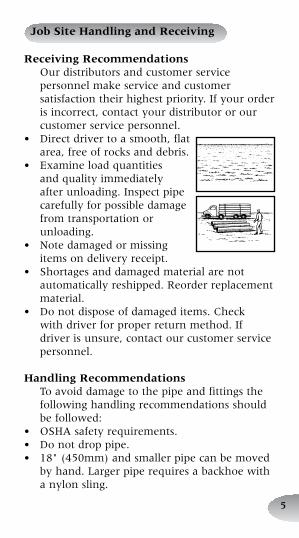
Receiving RecommendationsOur.distributors.and.customer.service.personnel.make.service.and.customer.satisfaction.their.highest.priority..If.your.order.is.incorrect,.contact.your.distributor.or.our.customer.service.personnel.
•. Direct.driver.to.a.smooth,.flat.area,.free.of.rocks.and.debris.
•. Examine.load.quantities.and.quality.immediately.after.unloading..Inspect.pipe.carefully.for.possible.damage.from.transportation.or.unloading.
•. Note.damaged.or.missing.items.on.delivery.receipt.
•. Shortages.and.damaged.material.are.not.automatically.reshipped..Reorder.replacement.material.
•. Do.not.dispose.of.damaged.items..Check.with.driver.for.proper.return.method..If.driver.is.unsure,.contact.our.customer.service.personnel.
Handling RecommendationsTo.avoid.damage.to.the.pipe.and.fittings.the.following.handling.recommendations.should.be.followed:
•. OSHA.safety.requirements.•. Do.not.drop.pipe.•. 18".(450mm).and.smaller.pipe.can.be.moved.
by.hand..Larger.pipe.requires.a.backhoe.with.a.nylon.sling.
�
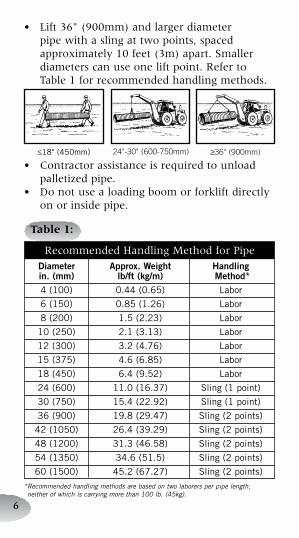
•. Lift.36".(900mm).and.larger.diameter.pipe.with.a.sling.at.two.points,.spaced.approximately.10.feet.(3m).apart..Smaller.diameters.can.use.one.lift.point..Refer.to.Table.1.for.recommended.handling.methods.
•. Contractor.assistance.is.required.to.unload.palletized.pipe.
•. Do.not.use.a.loading.boom.or.forklift.directly.on.or.inside.pipe.
Table 1:
Recommended.Handling.Method.for.Pipe Diameter Approx.Weight Handling in.(mm) lb/ft(kg/m) Method* 4(100) 0.44(0.65) Labor
6(150) 0.85(1.26) Labor
8(200) 1.5(2.23) Labor
10(250) 2.1(3.13) Labor
12(300) 3.2(4.76) Labor
15(375) 4.6(6.85) Labor
18(450) 6.4(9.52) Labor
24(600) 11.0(16.37) Sling(1point)
30(750) 15.4(22.92) Sling(1point)
36(900) 19.8(29.47) Sling(2points)
42(1050) 26.4(39.29) Sling(2points)
48(1200) 31.3(46.58) Sling(2points)
54(1350) 34.6(51.5) Sling(2points)
60(1500) 45.2(67.27) Sling(2points)
*�Recommended�handling�methods�are�based�on�two�laborers�per�pipe�length,��neither�of�which�is�carrying�more�than�100�lb.�(45kg).
≤18"(450mm) 24"-30" (600-750mm) ≥36" (900mm)
�
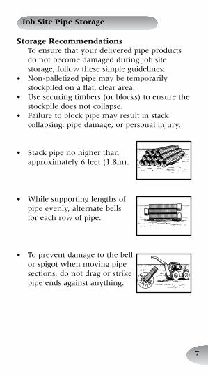
Job Site Pipe Storage
Storage RecommendationsTo.ensure.that.your.delivered.pipe.products.do.not.become.damaged.during.job.site.storage,.follow.these.simple.guidelines:
•. Non-palletized.pipe.may.be.temporarily.stockpiled.on.a.flat,.clear.area.
•. Use.securing.timbers.(or.blocks).to.ensure.the.stockpile.does.not.collapse.
•. Failure.to.block.pipe.may.result.in.stack.collapsing,.pipe.damage,.or.personal.injury.
•. Stack.pipe.no.higher.than.approximately.6.feet.(1.8m).
•. While.supporting.lengths.of.pipe.evenly,.alternate.bells..for.each.row.of.pipe.
•. To.prevent.damage.to.the.bell.or.spigot.when.moving.pipe.sections,.do.not.drag.or.strike.pipe.ends.against.anything.
�
Trench Construction
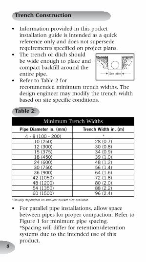
Table 2:
Minimum.Trench.Widths
PipeDiameterin.(mm) TrenchWidthin.(m)
4-8(100-200) * 10(250) 28(0.7) 12(300) 30(0.8) 15(375) 34(0.9) 18(450) 39(1.0) 24(600) 48(1.2) 30(750) 56(1.4) 36(900) 64(1.6) 42(1050) 72(1.8) 48(1200) 80(2.0) 54(1350) 88(2.2) 60(1500) 96(2.4)*Usually�dependent�on�smallest�bucket�size�available.
•. Information.provided.in.this.pocket.installation.guide.is.intended.as.a.quick.reference.only.and.does.not.supersede.requirements.specified.on.project.plans.
•. The.trench.or.ditch.should.be.wide.enough.to.place.and.compact.backfill.around.the.entire.pipe.
•. Refer.to.Table.2.for.recommended.minimum.trench.widths..The.design.engineer.may.modify.the.trench.width.based.on.site.specific.conditions.
Seetable
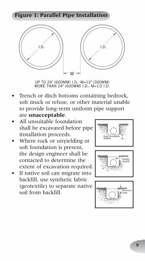
•. For.parallel.pipe.installations,.allow.space.between.pipes.for.proper.compaction..Refer.to.Figure.1.for.minimum.pipe.spacing..*Spacing.will.differ.for.retention/detention.systems.due.to.the.intended.use.of.this.product.
�
•. Trench.or.ditch.bottoms.containing.bedrock,.soft.muck.or.refuse,.or.other.material.unable.to.provide.long-term.uniform.pipe.support.are.unacceptable.
•. All.unsuitable.foundation.shall.be.excavated.before.pipe.installation.proceeds.
•. Where.rock.or.unyielding.or.soft.foundation.is.present,.the.design.engineer.shall.be.contacted.to.determine.the.extent.of.excavation.required.
•. If.native.soil.can.migrate.into.backfill,.use.synthetic.fabric.(geotextile).to.separate.native.soil.from.backfill.
Figure 1: Parallel Pipe Installation
UPTO24"(600MM)I.D.:M=12"(300MM)MORETHAN24"(600MM)I.D.:M=1/2I.D.
Goodfoundationneeded
Qualitybackfill
Minimumcover
10
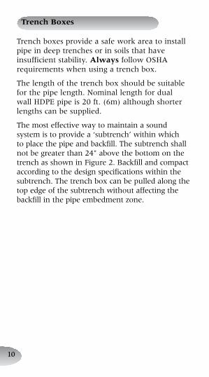
Trench.boxes.provide.a.safe.work.area.to.install.pipe.in.deep.trenches.or.in.soils.that.have.insufficient.stability..Always.follow.OSHA.requirements.when.using.a.trench.box.
The.length.of.the.trench.box.should.be.suitable.for.the.pipe.length..Nominal.length.for.dual.wall.HDPE.pipe.is.20.ft..(6m).although.shorter.lengths.can.be.supplied.
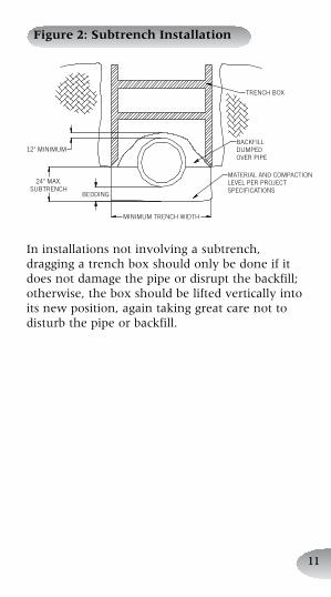
The.most.effective.way.to.maintain.a.sound.system.is.to.provide.a.‘subtrench’.within.which.to.place.the.pipe.and.backfill..The.subtrench.shall.not.be.greater.than.24".above.the.bottom.on.the.trench.as.shown.in.Figure.2..Backfill.and.compact.according.to.the.design.specifications.within.the.subtrench..The.trench.box.can.be.pulled.along.the.top.edge.of.the.subtrench.without.affecting.the.backfill.in.the.pipe.embedment.zone.
Trench Boxes
11
Figure 2: Subtrench Installation
12" MINIMUM
24" MAX.SUBTRENCH
BEDDING
MINIMUM TRENCH WIDTH
MATERIAL AND COMPACTIONLEVEL PER PROJECTSPECIFICATIONS
BACKFILLDUMPEDOVER PIPE
TRENCH BOX
In.installations.not.involving.a.subtrench,.dragging.a.trench.box.should.only.be.done.if.it.does.not.damage.the.pipe.or.disrupt.the.backfill;.otherwise,.the.box.should.be.lifted.vertically.into.its.new.position,.again.taking.great.care.not.to.disturb.the.pipe.or.backfill.
12
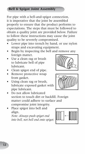
For.pipe.with.a.bell-and-spigot.connection,.it.is.imperative.that.the.joint.be.assembled.properly.to.ensure.that.the.product.performs.to.expectations..The.steps.that.must.be.followed.to.obtain.a.quality.joint.are.provided.below..Failure.to.follow.these.instructions.may.cause.the.joint.quality.to.be.severely.compromised.•. Lower.pipe.into.trench.by.hand,.or.use.nylon.
straps.and.excavating.equipment.•. Begin.by.inspecting.the.bell.and.remove.any.
foreign.matter.•. Use.a.clean.rag.or.brush.
to.lubricate.bell.of.pipe.lubricant.
•. Clean.spigot.end.of.pipe.•. Remove.protective.wrap..
from.gasket.•. Using.clean.rag.or.brush,.
lubricate.exposed.gasket.with.pipe.lubricant.
•. Do.not.allow.lubricated.section.to.touch.dirt.or.backfill..Foreign.matter.could.adhere.to.surface.and.compromise.joint.integrity.
•. Place.spigot.into.bell.and.align..Note: Always push spigot end into bell, not bell end onto spigot.
Bell & Spigot Joint Assembly
1�
Assemble.joint.using.one.of.the.following.methods..(For.smaller.diameters,.pipe.may.be.joined.manually.)•. For.all.methods,.ensure.bell.and.spigot.are.
adequately.“homed”.for.proper.installation.and.tight.joining.seal..If.no.homing.mark.is.present,.measure.the.depth.of.the.bell.and..use.a.crayon.or.other.material.to.place.a.homing.mark.on.appropriate.corrugation.of.the.spigot.end.
•. Installation.stubs,.mentioned.in.the.assembly.instructions,.can.be.purchased.or.made.following.the.information.on.page.15.
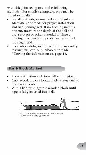
•. Place.installation.stub.into.bell.end.of.pipe.•. Place.wooden.block.horizontally.across.end.of.
installation.stub.•. With.a.bar,.push.against.wooden.block.until.
pipe.is.fully.inserted.into.bell.
Bar & Block Method
NOTE:�This�method�requires�use�of�installation�stub.�DO�NOT�push�directly�against�pipe.
1�
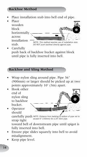
•. Place.installation.stub.into.bell.end.of.pipe.•. Place.
wooden.block.horizontally.across.installation.stub.
•. Carefully.push.back.of.backhoe.bucket.against.block.until.pipe.is.fully.inserted.into.bell.
Backhoe Method
NOTE:�This�method�requires�use�of�installation�stub.�DO�NOT�push�backhoe�directly�against�pipe.
•. Wrap.nylon.sling.around.pipe..Pipe.36".(900mm).or.larger.should.be.picked.up.at.two.points.approximately.10'.(3m).apart.
•. Hook.other.end.of.nylon.sling.to.backhoe.bucket.
•. Operator.should.carefully.push.strap.tight.toward.bell.of.downstream.pipe.until.spigot.is.fully.inserted.into.bell.
•. Ensure.pipe.slides.squarely.into.bell.to.avoid.misalignment.
•. Keep.pipe.level.
Backhoe and Sling Method
NOTE:�Distance�from�bedding�to�bottom�of�pipe�not�to�exceed�6"�(150mm)�for�a�20'�(6m)�pipe.
1�
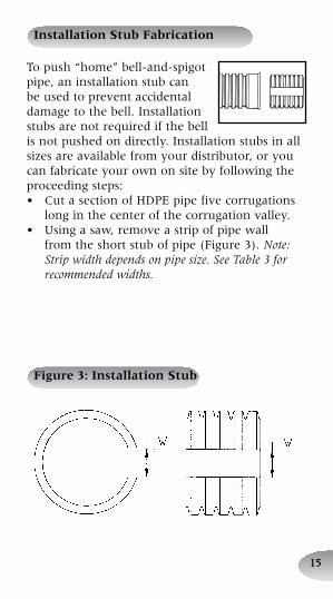
Installation Stub Fabrication
To.push.“home”.bell-and-spigot.pipe,.an.installation.stub.can.be.used.to.prevent.accidental.damage.to.the.bell..Installation.stubs.are.not.required.if.the.bell.is.not.pushed.on.directly..Installation.stubs.in.all.sizes.are.available.from.your.distributor,.or.you.can.fabricate.your.own.on.site.by.following.the.proceeding.steps:•. Cut.a.section.of.HDPE.pipe.five.corrugations.
long.in.the.center.of.the.corrugation.valley.•. Using.a.saw,.remove.a.strip.of.pipe.wall.
from.the.short.stub.of.pipe.(Figure.3)..Note: Strip width depends on pipe size. See Table 3 for recommended widths.
Figure 3: Installation Stub
1�
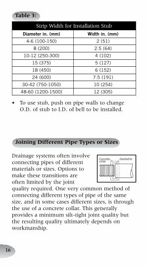
Table 3:
Strip.Width.for.Installation.Stub
Diameterin.(mm) Widthin.(mm)
4-6(100-150) 2(51)
8(200) 2.5(64)
10-12(250-300) 4(102)
15(375) 5(127)
18(450) 6(152)
24(600) 7.5(191)
30-42(750-1050) 10(254)
48-60(1200-1500) 12(305)
•. To.use.stub,.push.on.pipe.walls.to.change.O.D..of.stub.to.I.D..of.bell.to.be.installed.
Joining Different Pipe Types or Sizes
Drainage.systems.often.involve.connecting.pipes.of.different.materials.or.sizes..Options.to.make.these.transitions.are.often.limited.by.the.joint.quality.required..One.very.common.method.of.connecting.different.types.of.pipe.of.the.same.size,.and.in.some.cases.different.sizes,.is.through.the.use.of.a.concrete.collar..This.generally.provides.a.minimum.silt-tight.joint.quality.but..the.resulting.quality.ultimately.depends.on.workmanship.
Concretecollar
Geotextile
1�
•. A.concrete.collar.is.formed.by.butting.the.two.pipe.ends.tightly.together,.wrapping.the.junction.with.a.geotextile.to.keep.out.most.soil.and.concrete,.and.then.pouring.a.concrete.collar.that.covers.both.pipe.ends.
Another.option.may.be.using.fittings.or.adapters.specifically.designed.for.this.application..A.selection.of.fittings.designed.to.make.the.transition.from.one.material.directly.to.another.is.available..In.other.cases.a.fitting.may.need.to.be.used.in.combination.with.another.manufacturer’s.gasket.or.coupler.to.complete.the.transition..Transitions.made.in.this.manner.may.provide.for.a.higher.performance.joint.than.a.concrete.collar.
Manholes and Catch Basin/Connections
Manholes.or.catch.basins.can.be.used.at.changes.in.pipe.material,.size,.grade,.direction.and.elevation..Manholes.and.catch.basins.can.be.more.costly.than.other.alternatives.but.also.allow.grade.and.directional.changes.in.addition.to.changes.in.pipe.material.and.size.•. Local.regulations.should.be.consulted.to.
determine.if.manholes.or.catch.basins.are.required.at.any.or.all.pipe.changes.
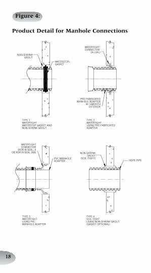
•. Refer.to.Figure.4.for.the.acceptable.methods.of.connecting.HDPE.pipe.to.manholes.or.basins.
1�
Figure 4:
NON-SHRINKGROUT
TYPE 1WATERTIGHTWATERSTOP GASKET ANDNON-SHRINK GROUT
WATERTIGHTCONNECTOR
(KOR-N-SEAL® IIOR KOR-N-SEAL 306) NON-SHRINK
GROUT(SOIL-TIGHT)PVC MANHOLE
ADAPTER HDPE PIPE
TYPE 2WATERTIGHTUSING PRE-FABRICATEDADAPTER
TYPE 4SOIL-TIGHTUSING NON-SHRINK GROUT(GASKET OPTIONAL)
TYPE 3WATERTIGHTUSING PVCMANHOLE ADAPTER
PRE-FABRICATEDMANHOLE ADAPTER
W / SMOOTHEXTERIOR
WATERSTOP®
GASKET
WATERTIGHT CONNECTOR
(A-LOK®)
Product Detail for Manhole Connections
1�
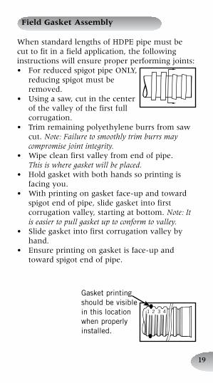
When.standard.lengths.of.HDPE.pipe.must.be.cut.to.fit.in.a.field.application,.the.following.instructions.will.ensure.proper.performing.joints:•. For.reduced.spigot.pipe.ONLY,.
reducing.spigot.must.be.removed.
•. Using.a.saw,.cut.in.the.center.of.the.valley.of.the.first.full.corrugation.
•. Trim.remaining.polyethylene.burrs.from.saw.cut..Note: Failure to smoothly trim burrs may compromise joint integrity.
•. Wipe.clean.first.valley.from.end.of.pipe...This is where gasket will be placed.
•. Hold.gasket.with.both.hands.so.printing.is.facing.you.
•. With.printing.on.gasket.face-up.and.toward.spigot.end.of.pipe,.slide.gasket.into.first.corrugation.valley,.starting.at.bottom..Note: It is easier to pull gasket up to conform to valley.
•. Slide.gasket.into.first.corrugation.valley.by.hand.
•. Ensure.printing.on.gasket.is.face-up.and.toward.spigot.end.of.pipe.
Field Gasket Assembly
1 2 3 4
Gasketprintingshouldbevisibleinthislocationwhenproperlyinstalled.
20
Fittings Assembly
This.section.includes.information.necessary.for:1.. Soil-tight.belled.fittings2.. Watertight.fittings3.. Repair.couplers•. Cut.pipe.to.desired.length.in.the.center.of.the.
corrugation.valley.before.placing.in.trench.•. Trim.remaining.polyethylene.burrs.from.saw.
cut..Note: Failure to smoothly trim burrs may compromise joint integrity.
•. Excavate.bedding.from.around.spigot.end.where.fitting.shall.be.used..A.bell.hole.will.help.prevent.dirt.and.debris.from.contaminating.joint.during.assembly.
•. Install.gasket.in.accordance.with.gasket.assembly.procedure.(page.19).
•. Measure.the.depth.of.the.bell.and.use.a.crayon.or.other.material.to.place.a.homing.mark.on.appropriate.corrugation.of.the.spigot.end.
21
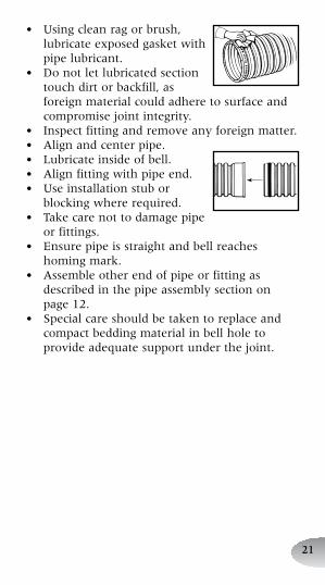
•. Using.clean.rag.or.brush,.lubricate.exposed.gasket.with.pipe.lubricant.
•. Do.not.let.lubricated.section.touch.dirt.or.backfill,.as.foreign.material.could.adhere.to.surface.and.compromise.joint.integrity.
•. Inspect.fitting.and.remove.any.foreign.matter.•. Align.and.center.pipe.•. Lubricate.inside.of.bell.•. Align.fitting.with.pipe.end.•. Use.installation.stub.or.
blocking.where.required.•. Take.care.not.to.damage.pipe.
or.fittings.•. Ensure.pipe.is.straight.and.bell.reaches.
homing.mark.•. Assemble.other.end.of.pipe.or.fitting.as.
described.in.the.pipe.assembly.section.on.page.12.
•. Special.care.should.be.taken.to.replace.and.compact.bedding.material.in.bell.hole.to.provide.adequate.support.under.the.joint.
22
HDPE.pipe.and.a.well-constructed.backfill.envelope.work.together.to.support.soil.and.traffic.loads..Correct.installation.will.ensure.long-term.trouble-free.service.for.all.types.of.pipe.systems.
Backfill Recommendations
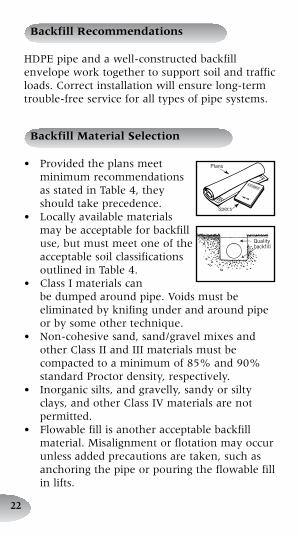
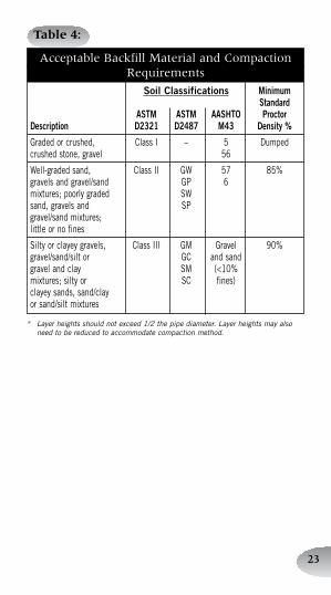
•. Provided.the.plans.meet.minimum.recommendations.as.stated.in.Table.4,.they.should.take.precedence.
•. Locally.available.materials.may.be.acceptable.for.backfill.use,.but.must.meet.one.of.the.acceptable.soil.classifications.outlined.in.Table.4.
•. Class.I.materials.can.be.dumped.around.pipe..Voids.must.be.eliminated.by.knifing.under.and.around.pipe.or.by.some.other.technique.
•. Non-cohesive.sand,.sand/gravel.mixes.and.other.Class.II.and.III.materials.must.be.compacted.to.a.minimum.of.85%.and.90%.standard.Proctor.density,.respectively.
•. Inorganic.silts,.and.gravelly,.sandy.or.silty.clays,.and.other.Class.IV.materials.are.not.permitted.
•. Flowable.fill.is.another.acceptable.backfill.material..Misalignment.or.flotation.may.occur.unless.added.precautions.are.taken,.such.as.anchoring.the.pipe.or.pouring.the.flowable.fill.in.lifts.
Backfill Material Selection
Plans
Specs
Qualitybackfill
2�
Table 4:
Acceptable.Backfill.Material.and.CompactionRequirements
SoilClassifications Minimum Standard ASTM ASTM AASHTO ProctorDescription D2321 D2487 M43 Density%
Gradedorcrushed, ClassI – 5 Dumpedcrushedstone,gravel 56
Well-gradedsand, ClassII GW 57 85%gravelsandgravel/sand GP 6mixtures;poorlygraded SWsand,gravelsand SPgravel/sandmixtures;littleornofines
Siltyorclayeygravels, ClassIII GM Gravel 90%gravel/sand/siltor GC andsandgravelandclay SM (<10%mixtures;siltyor SC fines)clayeysands,sand/clay orsand/siltmixtures
*� Layer�heights�should�not�exceed�1/2�the�pipe�diameter.�Layer�heights�may�also�need�to�be�reduced�to�accommodate�compaction�method.
2�
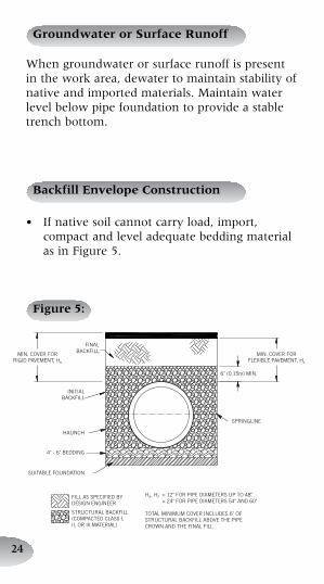
When.groundwater.or.surface.runoff.is.present.in.the.work.area,.dewater.to.maintain.stability.of.native.and.imported.materials..Maintain.water.level.below.pipe.foundation.to.provide.a.stable.trench.bottom.
Groundwater or Surface Runoff
Backfill Envelope Construction
Figure 5:
•. If.native.soil.cannot.carry.load,.import,.compact.and.level.adequate.bedding.material.as.in.Figure.5.
MIN. COVER FORRIGID PAVEMENT, HR
MIN. COVER FORFLEXIBLE PAVEMENT, HF
FINALBACKFILL
INITIALBACKFILL
HAUNCH
4" - 6" BEDDING
SUITABLE FOUNDATION
6" (0.15m) MIN.
SPRINGLINE
HR, HF = 12" FOR PIPE DIAMETERS UP TO 48" = 24" FOR PIPE DIAMETERS 54" AND 60"
TOTAL MINIMUM COVER INCLUDES 6" OFSTRUCTURAL BACKFILL ABOVE THE PIPECROWN AND THE FINAL FILL
FILL AS SPECIFIED BYDESIGN ENGINEER
STRUCTURAL BACKFILL(COMPACTED CLASS I,II, OR III MATERIAL)
2�
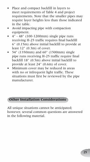
•. Place.and.compact.backfill.in.layers.to.meet.requirements.of.Table.4.and.project.requirements..Note.that.the.smaller.pipes.may.require.layer.heights.less.than.those.indicated.in.the.table.
•. Avoid.impacting.pipe.with.compaction.equipment.
•. 4".-.48".(100-1200mm).single.pipe.runs.receiving.H-25.traffic.requires.final.backfill.6".(0.15m).above.initial.backfill.to.provide.at.least.12".(0.3m).of.cover.
•. 54".(1350mm).and.60".(1500mm).single.pipe.runs.receiving.H-25.traffic.require.final.backfill.18".(0.5m).above.initial.backfill.to.provide.at.least.24".(0.6m).of.cover.
•. Minimum.cover.may.be.reduced.in.areas.with.no.or.infrequent.light.traffic..These.situations.must.first.be.reviewed.by.the.pipe.manufacturer.
Other Installation Considerations
All.unique.situations.cannot.be.anticipated;.however,.several.common.questions.are.answered.in.the.following.material..
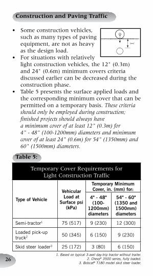
Table 5:
Temporary.Cover.Requirements.forLight.Construction.Traffic
TypeofVehicle
VehicularLoadat
Surfacepsi(kPa)
TemporaryMinimumCover,in.(mm)for:
4"-48"(100-
1200mm)diameters
54"-60"(1350and1500mm)diameters
Semi-tractor1 75(517) 9(230) 12(300)
Loadedpick-uptruck2 50(345) 6(150) 9(230)
Skidsteerloader3 25(172) 3(80) 6(150)
2�
Construction and Paving Traffic
•. Some.construction.vehicles,.such.as.many.types.of.paving.equipment,.are.not.as.heavy.as.the.design.load.
•. For.situations.with.relatively.light.construction.vehicles,.the.12".(0.3m).and.24".(0.6m).minimum.covers.criteria.discussed.earlier.can.be.decreased.during.the.construction.phase.
•. Table.5.presents.the.surface.applied.loads.and.the.corresponding.minimum.cover.that.can.be.permitted.on.a.temporary.basis..These criteria should only be employed during construction; finished projects should always have a minimum cover of at least 12" (0.3m) for 4" - 48" (100-1200mm) diameters and minimum cover of at least 24" (0.6m) for 54" (1350mm) and 60" (1500mm) diameters.
1.�Based�on�typical�3-axel�day-trip�tractor�without�trailer.2.�Chevy®�3500�series,�fully�loaded.
3.�Bobcat®�T180�model�skid�steer�loader.
2�
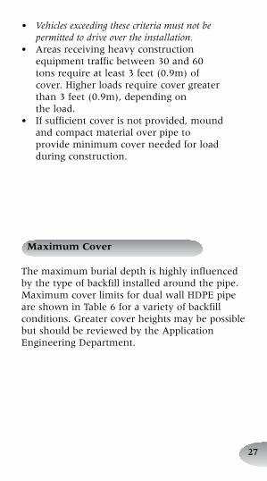
Maximum Cover
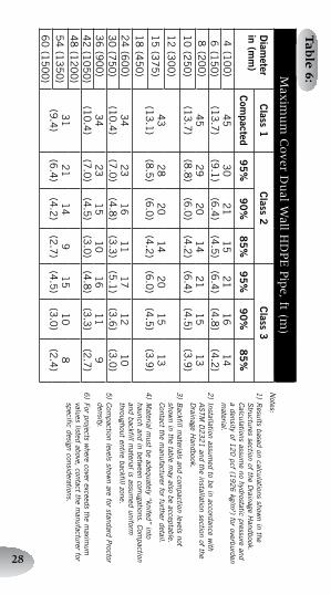
The.maximum.burial.depth.is.highly.influenced.by.the.type.of.backfill.installed.around.the.pipe..Maximum.cover.limits.for.dual.wall.HDPE.pipe.are.shown.in.Table.6.for.a.variety.of.backfill.conditions..Greater.cover.heights.may.be.possible.but.should.be.reviewed.by.the.Application.Engineering.Department.
• Vehicles exceeding these criteria must not be permitted to drive over the installation.
•. Areas.receiving.heavy.construction.equipment.traffic.between.30.and.60.tons.require.at.least.3.feet.(0.9m).of.cover..Higher.loads.require.cover.greater.than.3.feet.(0.9m),.depending.on..the.load.
•. If.sufficient.cover.is.not.provided,.mound.and.compact.material.over.pipe.to.provide.minimum.cover.needed.for.load.during.construction.
2�
Notes:
1)�R
esults�based�on�calculations�shown�in�the�
Structures�section�of�the�D
rainage�Handbook.�
Calculations�assum
e�no�hydrostatic�pressure�and�a�density�of�1
20
�pcf�(19
26
�kg/m3)�for�overburden�
material.
2)�Installation�assum
ed�to�be�in�accordance�with�
AS
TM�D
23
21
�and�the�installation�section�of�the�D
rainage�Handbook.
3)�B
ackfill�materials�and�com
paction�levels�not�show
n�in�the�table�may�also�be�acceptable.�
Contact�the�m
anufacturer�for�further�detail.
4)�M
aterial�must�be�adequately�“knifed”�into�
haunch�and�in�between�corrugations.�C
ompaction�
and�backfill�material�is�assum
ed�uniform�
throughout�entire�backfill�zone.
5)�C
ompaction�levels�show
n�are�for�standard�Proctor�
density.
6)�For�projects�w
here�cover�exceeds�the�maxim
um�
values�listed�above,�contact�the�manufacturer�for�
specific�design�considerations.
Max
imu
m.C
over.D
ual.W
all.HD
PE
.Pip
e,.ft.(m)
Diam
eterin(m
m)
Class1
Class2
Class3
Com
pacted9
5%
90
%8
5%
95
%9
0%
85
%
4(1
00
)4
5(1
3.7
)3
0
(9.1
)2
1
(6.4
)1
5
(4.5
)2
1
(6.4
)1
6
(4.8
)1
4
(4.2
)6
(15
0)
8(2
00
)4
5(1
3.7
)2
9(8
.8)
20
(6.0
)1
4(4
.2)
21
(6.4
)1
5(4
.5)
13
(3.9
)1
0(2
50
)
12
(30
0)
43
(13
.1)
28
(8.5
)2
0(6
.0)
14
(4.2
)2
0(6
.0)
15
(4.5
)1
3(3
.9)
15
(37
5)
18
(45
0)
24
(60
0)
34
(10
.4)
23
(7.0
)1
6(4
.8)
11
(3.3
)1
7(5
.1)
12
(3.6
)1
0(3
.0)
30
(75
0)
36
(90
0)
34
(10
.4)
23
(7.0
)1
5(4
.5)
10
(3.0
)1
6(4
.8)
11
(3.3
)9
(2.7
)4
2(1
05
0)
48
(12
00
)3
1(9
.4)
21
(6.4
)1
4(4
.2)
9(2
.7)
15
(4.5
)1
0(3
.0)
8(2
.4)
54
(13
50
)6
0(1
50
0)
Tab
le 6:
2�
Vertical Installations
•. HDPE.pipe.is.sometimes.installed.vertically.for.use.as.catch.basins.or.manholes,.meter.pits,.and.similar.applications.
•. Backfill.should.extend.a.minimum.of.12".(0.3m).completely.around.the.vertical.structure.
•. Backfill.material.recommendations.are.identical.to.those.for.a.horizontal.installation;.compaction.levels.and.maximum.lift.requirements.must.be.strictly.followed.(refer.to.Table.4.for.material.selection).
•. Height.of.the.vertical.structure.must.not.exceed.8'.(2.4m),.unless.the.Application.Engineering.Department.reviews.the.design.
•. If.traffic.will.be.driving.over.a.vertical.structure,.a.concrete.collar.similar.to.that.shown.in.Figure.6.shall.be.used.to.transfer.the.load.into.the.ground.
•. Cast.iron.frames.holding.grates.or.lids.must.be.seated.on.a.concrete.collar.or.similar.structure.so.that.the.weight.of.the.frame.and.grate.or.lid.is.transferred.into.the.ground,.not.to.the.vertical.pipe.
•. There.may.also.be.other.product.performance.limits.depending.on.the.application..Contact.Application.Engineering.for.further.information.
�0
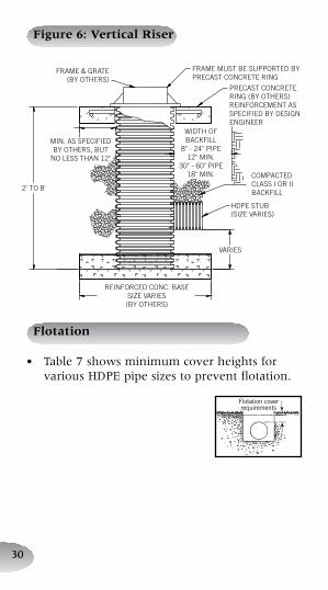
Figure 6: Vertical Riser
FRAME & GRATE(BY OTHERS)
2' TO 8'
REINFORCED CONC. BASESIZE VARIES(BY OTHERS)
VARIES
HDPE STUB(SIZE VARIES)
COMPACTEDCLASS I OR IIBACKFILL
WIDTH OFBACKFILL
8" - 24" PIPE12" MIN.
30" - 60" PIPE18" MIN.
PRECAST CONCRETERING (BY OTHERS)REINFORCEMENT ASSPECIFIED BY DESIGNENGINEER
FRAME MUST BE SUPPORTED BYPRECAST CONCRETE RING
MIN. AS SPECIFIEDBY OTHERS, BUT
NO LESS THAN 12"
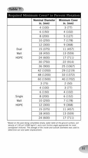
Flotation
•. Table.7.shows.minimum.cover.heights.for.various.HDPE.pipe.sizes.to.prevent.flotation.
Flotationcoverrequirements
�1
Table 7:
Required.Minimum.Cover*.to.Prevent.Flotation
NominalDiameter MinimumCover in.(mm) in.(mm)
4(100) 3(77)
6(150) 4(102)
8(200) 5(127)
10(250) 7(178)
12(300) 9(368)
Dual 15(375) 11(457)
Wall 18(450) 13(559)
HDPE 24(600) 17(711)
30(750) 22(914)
36(900) 25(1067)
42(1050) 29(1219)
48(1200) 33(1372)
60(1500) 40(1702)
3(75) 2(50)
4(100) 3(77)
6(150) 4(102)
Single 8(200) 6(152)
Wall 10(250) 7(178)
HDPE 12(300) 9(368)
15(375) 11(457)
18(450) 13(559)
24(600) 17(711)
*�Based�on�the�pipe�being�completely�empty,�water�table�at�the�ground�surface,�soil�density�of�130�pcf�(2083�kg/m3),�and�a�soil�friction�angle�appropriate�for�most�sand/gravel�mixtures.�The�average�of�the�inside�and�outside�diameters�was�used�to�determine�soil�and�water�displacement.
�2
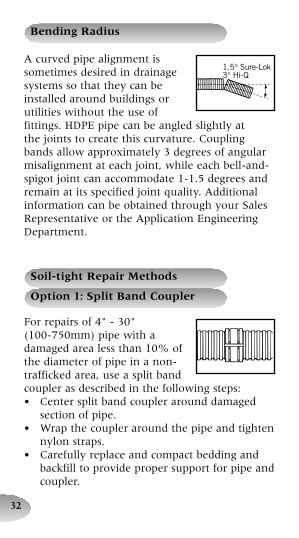
A.curved.pipe.alignment.is.sometimes.desired.in.drainage.systems.so.that.they.can.be.installed.around.buildings.or.utilities.without.the.use.of.fittings..HDPE.pipe.can.be.angled.slightly.at.the.joints.to.create.this.curvature..Coupling.bands.allow.approximately.3.degrees.of.angular.misalignment.at.each.joint,.while.each.bell-and-spigot.joint.can.accommodate.1-1.5.degrees.and.remain.at.its.specified.joint.quality..Additional.information.can.be.obtained.through.your.Sales.Representative.or.the.Application.Engineering.Department.
Bending Radius
1.5°Sure-Lok3°Hi-Q
For.repairs.of.4".-.30"..(100-750mm).pipe.with.a.damaged.area.less.than.10%.of.the.diameter.of.pipe.in.a.non-trafficked.area,.use.a.split.band.coupler.as.described.in.the.following.steps:•. Center.split.band.coupler.around.damaged.
section.of.pipe.•. Wrap.the.coupler.around.the.pipe.and.tighten.
nylon.straps.•. Carefully.replace.and.compact.bedding.and.
backfill.to.provide.proper.support.for.pipe.and.coupler.
Soil-tight Repair Methods
Option 1: Split Band Coupler
��
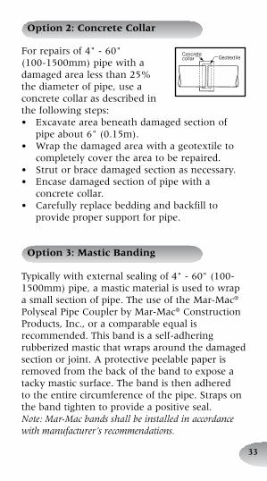
For.repairs.of.4".-.60"..(100-1500mm).pipe.with.a.damaged.area.less.than.25%.the.diameter.of.pipe,.use.a.concrete.collar.as.described.in.the.following.steps:•. Excavate.area.beneath.damaged.section.of.
pipe.about.6".(0.15m).•. Wrap.the.damaged.area.with.a.geotextile.to.
completely.cover.the.area.to.be.repaired.•. Strut.or.brace.damaged.section.as.necessary.•. Encase.damaged.section.of.pipe.with.a.
concrete.collar.•. Carefully.replace.bedding.and.backfill.to.
provide.proper.support.for.pipe.
Option 2: Concrete Collar
GeotextileConcretecollar
Option 3: Mastic Banding
Typically.with.external.sealing.of.4".-.60".(100-1500mm).pipe,.a.mastic.material.is.used.to.wrap.a.small.section.of.pipe..The.use.of.the.Mar-Mac®.Polyseal.Pipe.Coupler.by.Mar-Mac®.Construction.Products,.Inc.,.or.a.comparable.equal.is.recommended..This.band.is.a.self-adhering.rubberized.mastic.that.wraps.around.the.damaged.section.or.joint..A.protective.peelable.paper.is.removed.from.the.back.of.the.band.to.expose.a.tacky.mastic.surface..The.band.is.then.adhered.to.the.entire.circumference.of.the.pipe..Straps.on.the.band.tighten.to.provide.a.positive.seal...Note: Mar-Mac bands shall be installed in accordance with manufacturer’s recommendations.
��
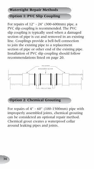
For.repairs.of.12".-.24".(300-600mm).pipe,.a.PVC.slip.coupling.is.recommended..The.PVC.slip.coupling.is.typically.used.when.a.damaged.section.of.pipe.is.cut.and.removed.in.an.existing.line..Couplings.provide.a.bell-bell.connection.to.join.the.existing.pipe.to.a.replacement.section.of.pipe.or.other.end.of.the.existing.pipe..Installation.of.PVC.slip.coupling.should.follow.recommendations.listed.on.page.20.
Watertight Repair Methods
Option 1: PVC Slip Coupling
FIELD CUT ENDS
PVC SLEEVES
REPLACEMENT SECTION
Option 2: Chemical Grouting
For.repairs.of.4".-.60".(100-1500mm).pipe.with.improperly.assembled.joints,.chemical.grouting..can.be.considered.an.optional.repair.method..Chemical.grout.creates.a.waterproof.collar.around.leaking.pipes.and.joints.
��
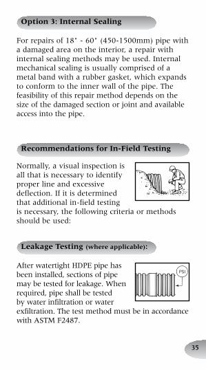
Option 3: Internal Sealing
For.repairs.of.18".-.60".(450-1500mm).pipe.with.a.damaged.area.on.the.interior,.a.repair.with.internal.sealing.methods.may.be.used..Internal.mechanical.sealing.is.usually.comprised.of.a.metal.band.with.a.rubber.gasket,.which.expands.to.conform.to.the.inner.wall.of.the.pipe..The.feasibility.of.this.repair.method.depends.on.the.size.of.the.damaged.section.or.joint.and.available.access.into.the.pipe..
Normally,.a.visual.inspection.is.all.that.is.necessary.to.identify.proper.line.and.excessive.deflection..If.it.is.determined..that.additional.in-field.testing..is.necessary,.the.following.criteria.or.methods.should.be.used:
Recommendations for In-Field Testing
Leakage Testing (where applicable):
After.watertight.HDPE.pipe.has.been.installed,.sections.of.pipe.may.be.tested.for.leakage..When.required,.pipe.shall.be.tested.by.water.infiltration.or.water.exfiltration..The.test.method.must.be.in.accordance.with.ASTM.F2487.
PSI
��
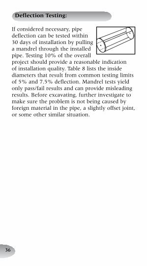
Deflection Testing:
If.considered.necessary,.pipe.deflection.can.be.tested.within.30.days.of.installation.by.pulling.a.mandrel.through.the.installed.pipe..Testing.10%.of.the.overall.project.should.provide.a.reasonable.indication.of.installation.quality..Table.8.lists.the.inside.diameters.that.result.from.common.testing.limits.of.5%.and.7.5%.deflection..Mandrel.tests.yield.only.pass/fail.results.and.can.provide.misleading.results..Before.excavating,.further.investigate.to.make.sure.the.problem.is.not.being.caused.by.foreign.material.in.the.pipe,.a.slightly.offset.joint,.or.some.other.similar.situation.
��
All�sales�of�our�product�are�subject�to�a�limited�warranty�and�purchasers�are�solely�responsible�for�installation�and�use�of�our�products�and�determining�whether�a�product�is�suited�for�any�specific�needs.�Please�consult�a�full�copy�of�the�Terms�and�Conditions�of�Sale�for�further�details.
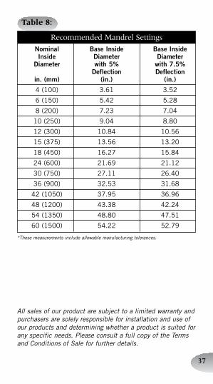
Table 8:
Recommended.Mandrel.Settings
Nominal BaseInside BaseInside Inside Diameter Diameter Diameter with5% with7.5% Deflection Deflection in.(mm) (in.) (in.)
4(100) 3.61 3.52
6(150) 5.42 5.28
8(200) 7.23 7.04
10(250) 9.04 8.80
12(300) 10.84 10.56
15(375) 13.56 13.20
18(450) 16.27 15.84
24(600) 21.69 21.12
30(750) 27.11 26.40
36(900) 32.53 31.68
42(1050) 37.95 36.96
48(1200) 43.38 42.24
54(1350) 48.80 47.51
60(1500) 54.22 52.79
*�These�measurements�include�allowable�manufacturing�tolerances.

DIRECT CONTACTCustomer Service888-FOR PIPE (367-7473)Fax 888-FAX PIPE (329-7473) 24 hours a day
Hancor “Terms and Conditions of Sale” are available on the Hancor web site, www.hancor.comHancor® is a registered trademark of Hancor, Inc. Mar-Mac® is a registered trademark of Mar-Mac® Construction Products, Inc.Chevy® is a registered trademark of General Motors Corporation.Bobcat® is a registered trademark of Bobcat Company.A-LOK® is a registered trademark of A-LOK Products, Inc.Kor-N-Seal® is a registered trademark of NPC, Inc.© 2007 Hancor, Inc. 28512003/0507
ELECTRONIC MEDIAWeb SiteFind market- and application-specific information and the latest industry news at our On-Line Pipeline – www.hancor.com
401 Olive St., Findlay, OH 45840


