Corrosion Control of Inter-Hull Spaces - Ship Structure Committee
129
NTIS #PB96-1 67580 SSC-390 CORROSION CONTROL OF INTER-HULL SPACES ‘his ckxument hw been approved for public release and salq its distribution is unlimited SHIP STRUCTURE COMMITTEE 1996
Transcript of Corrosion Control of Inter-Hull Spaces - Ship Structure Committee

NTIS #PB96-1 67580
SSC-390
CORROSION CONTROL OFINTER-HULL SPACES
‘his ckxument hw been approvedfor public release and salq its
distribution is unlimited
SHIP STRUCTURE COMMITTEE
1996


SHP STRUCTURFCOMI MITTFE
The SHIP STRUCTURE COMMllTEE is constituted to prosecute a research program to improve the hull structures of ships and othermarine structures by an extension of knowledge pertaining to design; materials, and methods of construction.
RADM J. C, Card, USCG (Chairman)Chief, Office of Marine Safety, Security
and Environmental ProtectionU. S. Coast Guard
Mr. Thomas H. Peirce Mr. Edwin B. SchimlerMarine Research and Development
Dr. Donald tiuAssaciate Administrator for Ship- Senior Vice President
Coordinator building and Technology Development Ameri@n Bureau of ShippingTransportation Development Center Maritime AdministrationTransport Canada
Mr. Robert McCarthy Mr. Thomas ConnorsDirector, Survtiability and Structural
Dr. Ross GrahmActing Director of Engineering (N7) Head, Hydronautics Section
Integrity Group (SEA 03P) Military Sealifl Command Defence Research Establishment-AtlanticNaval Sea Systems Command
FXFCUTIVF DIRFC OHT CONTRACTING OFFICFR TEC HNICAI RFPRFSE NTATIVE
CDR Stephen E, Sharpe, USCG Mr. William J, SiekierkaU. S. Coast Guard Naval Sea Systems Command
SUBCOMMllTEE
The SHIP STRUCTURE SUBCOMMl_iTEE acts for the Ship Structure Committee on technical matters by providing technicalcoordination for determinating the goals and objectives of the program and by evaluating and interpreting the results in terms ofstructural design, construction, and operation.
MILITARY SEALIFT COMMAND
Mr. Robert E. Van Jones (Chairman)Mr. Rickard A AndersonMr. Michael W. ToumaMr. Jeffrey E. Beach
AMERICAN BUREAU OF SHIPPING
Mr. Glenn AsheMr. John F. ConIonMr. Phillip G. RynnMr, William Hanzalek
MARITIME ADMINISTRATION
Mr. Frederick Seibold’Mr. Richard P. VoelkerMr. Chao H. LinDr. Walter M. Maclean
NAVAL SEA SYSTE MS COMMAND
Mr. W. Thomas PackardMr. Charles L NullMr. Edward KadalaMr, Allen H. Engle
U.S. COAST GUARD
CAPT George WrightMr. Walter LincolnMr. Rubin Sheinberg
TFLANSPORT CANADA
Mr, John GrinsteadMr. Ian BaylyMr. David L. StocksMr. Peter 17monin
DEFENCE RESEARCH ESTABLISHMENT ATIANTIC
Dr. Neil PeggLCDR Stephen GibsonDr. Roger HollingsheadMr. John Porter
SOCIE_WOF NAVAL ARCHITECTS ANDMARINE ENGINEERS
Dr. William Sandberg
CANADA CENTRE FOR MINERALS ANDENERGY TECHNQLO GIES
Dr, William R. Tyson
NATIONAL ACADEMY OF SCIENCES -RINE BOARD
Dr. Robert Sielski
NATIONAL ACADEMY OF SCIENCES -OMMITTFF ON RUCTLI RES
Dr. John Landes
U, S. NAVAL ACADE MY WI ~lNGRFSF4RCH COUNC1lDr. Ramswar Bhattacharyya Dr. Martin Prager
AMFRICAN IRON ANIT STFFI lNSTITl ITFMr. Alexander D. Wilson
OFFICE OF NAVAI RFSFAR~ HDr. Yapa D. S. Rajapaske
EC NICAI ADIVSORY GROUP TO THlNT:RN~TIONAL STANDARDS ORGANl~T?ON
u. s. MASSACHUSEITS INSTITLJTF OF TFCHNOI ~GY
CAPT Charles Piersali CAPT Alan J. Brown
s~RMr. J=on MillerMassachusetts Institute of T~hnology

Member Agencies:
Anerim Bureau of Sh@ping, De fence Research Establishment Atlantic
Maritime AdministrationMilitaiy Sealift Command
Navti Sea Systems CommandTransport Canada
United States Coast Guard
~ c Addrss Correswndence to:
Executive Director
Ship ‘Ship Structure CommitteeU.S. Coast Guard (G-MMS/SSC)
Structure2100 Second Street, S.W.Washin ton, D.C. 205=-0001
CommitteeYPh:(202 267-0003
Fax:(202) 267-4616
An Interagency Advisory Committee SSC-390SR-1366
26 April 1996
CORROSION CONTROL OF INTER-HULL SPACES
The advent of double hull vessels provides a new era of spillresistant tankers. However, with this new increased protectioncomes the problem of maintaining the closed-in double-bottomspaces. This study, focused primarily on merchant vessels,follows a worldwide survey of commercial shippers and shipyardsfor the U.S. Navy. The results conclude that the use of readilyavailable coating systems, but with increased emphasis on qualityof surface preparation and personnel training, will yieldimpressive results. If these practices are put in place, theNorth American shipping companies can achieve dramatic savings inrecoating of tanks, structural repairs, and the requisite repairlaydays.
Rear Admir&f, U.S. Coast GuardChairmanr Ship” Structure Committee
.
(THISPAGE INTENTIONALLY L137 BMNK)

I ckll!~r-1 HGIJUI ! U-U II IGIIMLILHI F~~lS
1. Report No. 2. Government Accession No. 3. Recipient’s Catalog No.
SSC-390 P1396-167580
4 Title and Subtitle ~ 5. Report Date
January 1996CORROSK)N CONTROL OF INTER-HULL SPACES 6. Performing Organization Coda
8. Performing Organization Report No.
‘“‘Ut%%kutq AL $himko, D. Cisccm SR-1366>.Performing Agency Name and Addre= 10. Work Unit No. (TRAIS)
M. Rosenblatt & Son, Inc.
2341 Jefferson Davis Highway, Suite 500 ““ ‘nti=i?O~?$%D-4502Arlington, VA 22202-3885 13. Type of Report and Periid Covered
12. Sponsoring Agency Nanw and AddressShip Structure Committee
Final Report
CIO U.S. Coast Guard (G-MMS/SSC)2100 Second St. SW 14. Spormoting.. Agency ~~
Washington, DC 20593-0001 G-MI5. Supplerrmtary Notes
Sponsored by the Ship Structure Committee. Jointly funded by its member agenciea.
6. Abstract
This report expands upon the work conducted by the U.S. Navy to develop a tankpresewation protocol with aservice life of 15t020 years. This report focuses on controllingcorrosion in the region between the inner and outer hulls in new double hull designs. Thisarea is treated as either a void or a seawater ballast tank. The Oil Pollution Act of 1990 hasprecipitated increased interest by ship owners, ship builders, ship operators, and Classificationsocieties to mialyze and evaluate the long term corrosion protection requirements of the inter-hull space of double hull designs. A recommended inter:hull space presemation protocol isprovided which is based upon information gathered from classification societies; U.S.,European, and Japanese shipy@s; coating manufacturers; maritime mag@ne articles; reports;and the U.S. Navy. Conclusions are provided concerning the use of cathodic protection,vapor phase inhibitors, and metal spray coatings. Guides were developed to evaluate whetherto repair or replace the coating of inter-hull spaces; inspection of the coating of inter-hullspaces; quality assurance requirements for application of coatings to steel surfaces of inter-hull areas; and training of journeyman painters, painting sypemisors, and paint inspectors fordouble hull ships.
7. Key Words 1& Distribution Statemant
CorrosionDistribution Unlimited, Available From:National Technical Information Service
Inter-huIl U.S. Department of CommerceCoating Springfield, VA 22151 Ph. (703) 487-4650
9. Security Classif. (of this report) 20. SECURllY CIASSIF. (of this page) 21. No. of Pages Z?. Pricsr 996
Unclassified Unclassified 128 $Paper- 31.00Microf-$14.00
—-—— ----Form DOT F 1700.7 (8/72) Rqroductfon of form and completed page is authodred.
. . .111
Ms’r En;:%ammUnited Statm Dep&mrd 01Corrrmca
NallomlInstlMdofStandards md Tmhnolcqy
MEUUC CONVERSION CARDApproximateConversions to MetricMeasures -“ —
ir~Symbol When You Know MtiltipIy by To Find Symbol @~
LENGTH g-
in inches 2.5 centimeters cm ~fl feet 30 centimeters cm ~yd yards 0,9 meters A—mi miIes 1.6 kilometers he
AREA~2 squareinches 6,5 squarecentimeters cm 2 —f~2 squarefeet 0.09 square nletem mz =@L SqU~ yards 0.8 squaremeters m2 ~mi2 square miIes 2.6 squarekilometers krnz N ~
acres 0.4 hectares ha —MASS (weight)
Oz ounces 28lb 0.45 %&s
g~pounds kg ~shorttons 0.9 metricton t~(2000 Ib) u=
VOLUMEtsll teaswns 5 miMiters m[.~;p tabl&poons
..—15 milliliters rnL=
cubic inches 16 millili~ers mL~fl oz fluidounces 30 miMIiters IIILEc cups 0.24 liters L =~pt pints 0.47 liters L~qt quarts 0,95 liters L~gd gallons 3.8 liters L=ft3 cubicfeet 0.03 cubicmeters m3 —yd 3 cubicyards 0.76 cubicmeters m3
TEMPERATURE (exact) m~“F &g~eS subtract32, degrees “C ~
Fahrertheh multidv by 5B Celsius..-.
f@PmX~ate Conversions fmm Me~c Me~uRs
Symbol When You Know MIJltipiy by To Find Symbol
LENGTHmm millimeters 0.04 inches incm centimeters 0.4 inches inm metem 3.3 feet Rm meters 1.1 y~dskm kilometers 0,6
ydmiles mi
AREAcm2 squarecentimeters ~,\6 squareinches ~2
rn2 squaremetem . Squm yards y~2
km 2 squareIcilometem ~.~ squaremiles mi2ha hectares acres
(10,0@0m2) ‘MASS (weitit)
grams 0.035 ounces 02:g kilograms 2.2 pounds lbt metricton 1J shorttons
(l,W kg)VOLUME
mL milliliters 0.03 fluid ounces fl OzmL milliliter 0.06 cubic inches ~3
L lders 2.1 pints ptL liters 1,06 quarts qt
:. L titers 0,26 gallons ::~3 cubicmeters 35 cubic fedm3 cubicmetem 1,3 cubicyards ~d3
TEMPERATURE _(exact) ““c degrees multiplyby 9/5, degrees *F
Celsius add 32 Fahrenheit
,_ 40 -20 0 20 3.7 60 00 100
4’0 0 32 80 98.6 160 2i2water keezes body temperature water hi Is
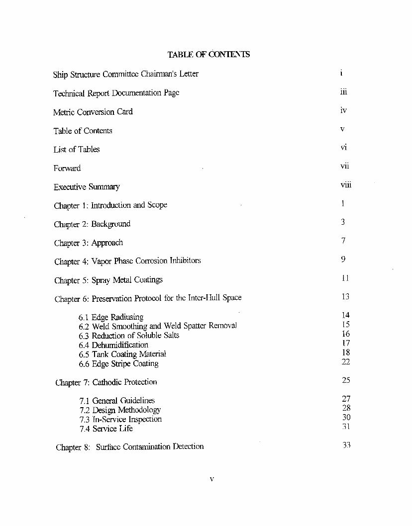
TABLE OF @NTENTS
Ship Structure Committee Chairman’s IAer i
. . .111Technical Report Documentation Page
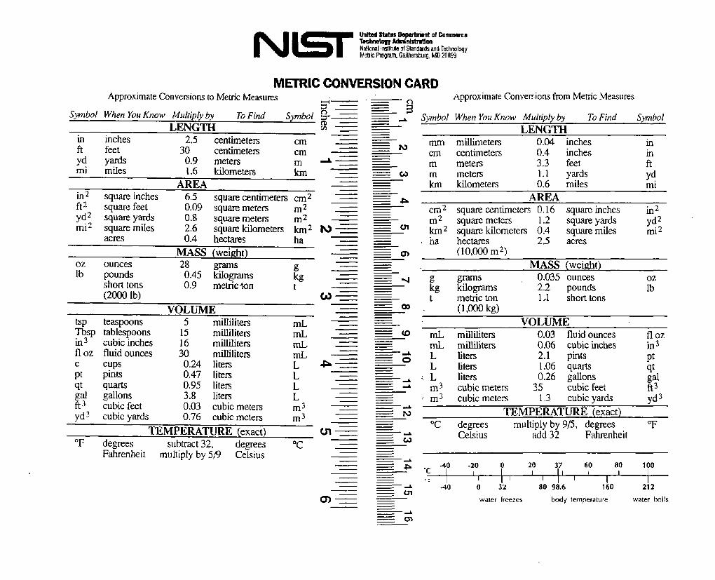
ivMetric Conversion Card
Table of Contents v
viList of Tables
viiForward. ..
VlllExecutive Summary
1Chapter 1: Introduction and Scope
3Chapter 2: Background
7Chapter 3: Approach
9Chapter 4: Vapor Phase Corrosion Inhibitors
11Chapter 5: Spray Metal Coatings
Chapter 6: Preservation Protocol for the Inter-Hull Space 13
141516171822
6.1 Edge Mdiusing6.2 Weld Smoothing and Weld Spatter Removal6.3 Reduction of Soluble Salts6.4 Dehumidification6.5 Tank Coating Material6.6 Edge Stripe Coating
25Chapter 7: CathodicProtection
27283031
7.1 General Guidelines7.2 Design Methodolo~7.3 Ln-Serviee Inspection7.4 Service Life
33Chapter 8: Surface Contamination Detection
v

Chapter 9: Edge Protection Systems
Chapter 10: Sensors
Chapter 11: Guides
Chapter 12: Conclusions
Chapter 13: Proposed Studies
References
Appendix A Surface Preparation Procedure
Appendix B: Painting Procedure
Appendix C: Guide on Repair or Replace
Appendix D: Guide on Inspection
Appendix E: Guide on Quality Assurance
Appendix F: Guide entraining
LIST OF TABLES
Table 7.1 Galvanic Series of Metals
Table 7.2 Anode Material Electrochemical Properties
Table 7.3 Driving Potential (volts dc)
Table 7.4 Required Current Density for Steel
Table 8.1 Temperature Correction
37
39
41
43
45
47
A-1
B-1
c-1
D-1
E-1
F-1
25
26
27
29
34
vi

FORWARD
This project was fhnded by the Ship Structure Committee. The Ship StructureCommittee is an interagency committee sponsoring ship structure research projects. Itsmembership is made up equally from the American Bureau of Shipping, Defence ResearchEstablishment Atlantic (Canadian National Defence), Maritime Administration MilitaqSealifi Command Naval Sea Systems CommanL Transport Cana@ and the U.S. CoastGuard.
The research was conducted by the Arlington, VA office of M. Rosenblatt & Son, Inc.The project is entitled SR-1366, Corrosion Control of Inter-Hull Spaces. The objective of theproject is to provide guides and standards to the marine industry that will lead to fewerfailures of ship inter-hull spaces due to long term corrosion. This project is intended toexpand upon the Engineering for Reduced Maintenance (ERM) tank presewation initiativeconducted by the Naval Sea Systems Command (NAVSEA) Materials Engineering Group(03M).
vii

lmxumvE !NJMMARY
This report expands upon the work conducted by the Naval Sea Systems Command todevelop a tank presewation protocol which is intended to achieve a service life of 15 to 20years. This report focuses on controlling corrosion in the region between the inner and outerhulls in new double hull designs. This area is treated as either a void or a seawater ballasttank. With the passage of the United States Oil Pollution Act (OPA) in 1990, all new tankerstrading in the U.S. are required to be of a double hull design effective January 1, 1994. TheOPA has precipitated increased interest by ship owners, ship builders, ship operators, andclassification societies to analyze and evaluate the long term corrosion protection requirementsof the inter-hull space of double hull designs.
To produce this report, information was obtained from classification societies; U.S.,European, and Japanese shipyards; coating manufacturers; rnmitime magazine articles; reports;and the U.S. Navy to determine the current maintenance and repair practices for inter-hullspaces. This information was assimilated and orgtized into a recommended inter-hull space -prese~ation protocol. The protocol unified individual “good painting practice” inputs fromthe various references into a process which is expected to provide 20 years of corrosionprotection to the inter-hull space. The essential elements of the inter-hull preservationprotocol are:
● Radius to 3 mm all edges, drain holes, coarning, hand holds, foot holds, ladders, etc.;
“ Smooth welds and remove weld spatter;
● Reduce soluble salts on the substrate to less than 3 p#cm2;
● Maiitain a relative humidity of 50°/0or less during the surface preparation and coatingapplication processes;
● Apply two coats of a light color~ high buil~ high solids epoxy coating system,
● Apply stripe coats to areas not accessible to the paint spray gun and to coating failuresusceptible areas such as edges, weld seams, pipe hangers, foot holds, etc. after the fmt fullcoat and prior to the topcoat.
The conclusions reached from this investigation include:
● ‘The presewation of the inter-hull space is a major concern for all participants, includingship owners, classification societies, coating manufacture, and shipyards.
● The material condition of the inter-hull space and “consequence analysis” determine whichpreservation protocol is “most suitable”.
. ..Vlll

● The best corrosion protection system for the inter-hull area combines a sacrificial cathodicprotection system with a hard barrier coating system.
● A catiodic protection system can be designed for the inter-hull area in such a way that it iscompatible with a coating system.
● A coating preservation protocol for the inter-hull area is provided which is expected toprovide a 15 to 20 year service life.
● Metal spray coating systems are not practical for corrosion protection of the inter-hull areadue to poor production rates, high cost, specialized equipmenq and increased operator trainingrequirements.
● Vapor phase inhibitors are not recommended for the inter-hull area due to theincompatibility of the inhibitors when the inter-hull space is used as a ballast tank.
“ The steel substite of the inter-hull area should be tested to determine the level of chloridecontamination. The Bresle Test Kit with an electronic conductivity meter can quickly providemeasurements of the chloride contamination of the steel substrate.
● No single tool can perform al1 edge roundinghadiusing in the inter-hull space. Seven inchor nine inch disc sanders or grindexs with 24 grit aluminum oxide abrasive pads are best forstraight runs. Smaller high speed die grinders with various attachments (i.e., flame shapedcarbide burrs, concave radius deburring hea~ or conical stone tips) are best for hard to reachareas. Mastics, polysulfides, and an epoxy coating system specifically formulated for edgecovering capacity show initial promise as edge protection systems.
● Sensors which measure the change of the substrate’s electrical resistivity are recommendedfor the inter-hull space. Hard wired and wireless systems designed for other uses can beadapted to the inter-hull space.
Guides have been developed to:
QEvaluate whether to repair or replace the coating of inter-hull spaces;● Inspect the coating system of inter-hull spaces;● Provide quality assurance requirements for application of coatings to steel surfaces of inter-hull areas;● Train journeyman paintem, painting supervisors, and paint inspectors for double hull ships.
ix

(’IHIS PAGE INTENTIONALLY LEIT BUNK)
CHAFrERl
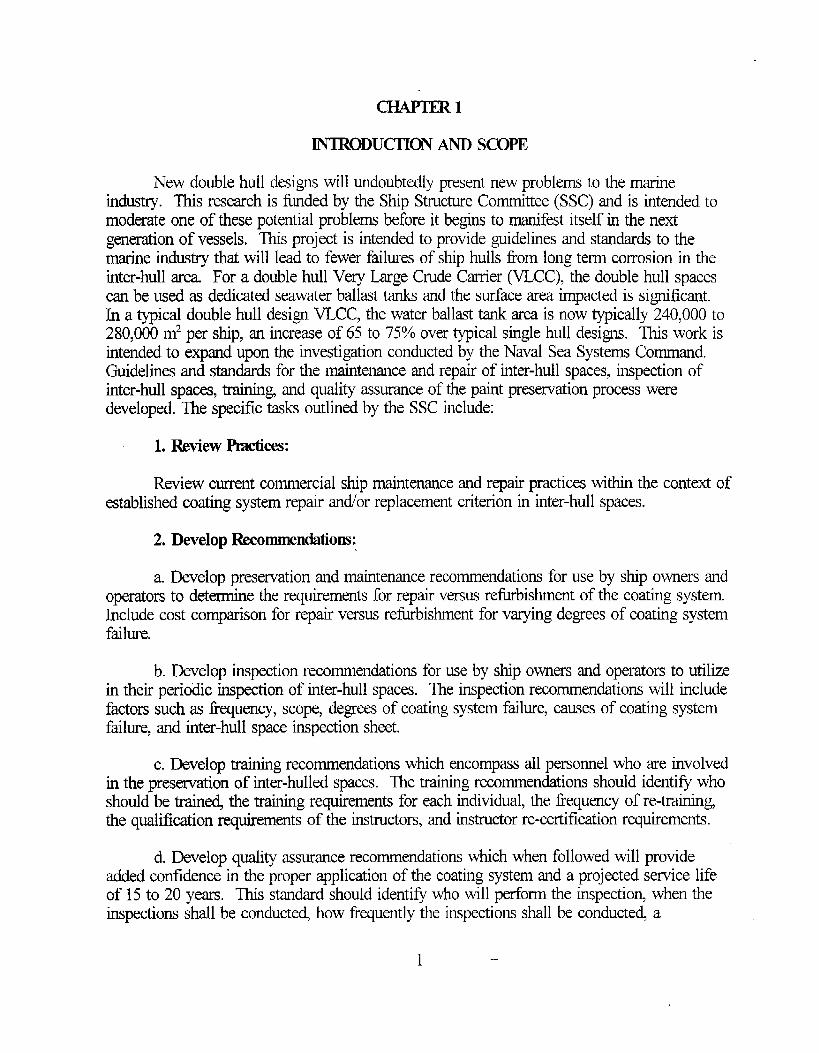
INTRODUCTION AND SCOPE
New double hull designs will undoubtedly present new problems to the marineindustry. This research is funded by the Ship Structure Committee (SSC) and is intended tomoderate one. of these potential problems before it begins to manifest itself in the nextgeneration of vessels. This project is intended to provide guidelines and standards to themarine industry that will lead to fewer failures of ship hulls from long term corrosion in theinter-hull area For a double hull Very Large Crude Carrier (VLCC), the double hull spacescan be used as dedicated seawater ballast tanks and the surface area impacted is significant.In a ~ical double hull design VLCC, the water ballast tank area is now typically 240,000 to280,000 m2 per ship, an increase of 65 to 75V0over typical single hull designs. This work isintended to expand upon the investigation conducted by the Naval Sea Systems Command.Guidelines and standards for the maintenance and repair of inter-hull spaces, inspection ofinter-hull spaces, training, and quality assurance of the paint preservation process weredeveloped. The specific tasks outlined by the SSC include:
1. Review Pmctices:
Review current commercial ship maintenance and repair practices within the context ofestablished coating system repair ancVorreplacement criterion in inter-hull spaces.
2. Develop Recomtnendations:
a. Develop presemation and maintenance recommendations for use by ship owners andoperators to determine the requirements for repair versus refurbishment of the coating system.Include cost comparison for repair versus refurbishment for varying degrees of coating systemfailure.
b. Develop inspection recommendations for use by ship owners and operators to utilizein their perio”dic inspection of inter-hull spaces. The inspection recommendations will includefactors such as frequency, scope, degrees of coating system failure, causes of coating systemfailure, and inter-hull space inspection sheet.
c. Develop training recornrnencMions which encompass all personnel who are involvedin the preswation of inter-hulled spaces. The training recommendations should identifj whoshould be train~ the training requirements for each individual, the frequency of re-trtig,the qualifi~tion requirements of the instructor, and instructor re-certification requirements.
d. Develop quality assurance recommendations which when followed will provideadded conildence in the proper application of the coating system and a projected service lifeof 15 to 20 years. This standard should identi~ who will petiorm the inspection when theinspections shall be conductei how frequently the inspections shall be conducted a
1 ---

recommended quality assurance check off sheet which includes quali~ assurance check pointsduring the coating application process, and recommendations for resolving each attributewhich does not pass the quality assurance check.
The review of current ship maintenance and repair practices such as vapor phasecorrosion inhibito~, spray metal coatings, and edge protection systery.s are summarized inChaptexx 4, 5, and 9, respectively.
The proposed preservation protocol for inter-hull spaces is described in detail inChapter 6. A design methodology for a cathodic protection system for the inter-hull space isprovided in Chapter 7. A recommended procedure for detecting surface contamination isdescribed in Chapter 8. Chapter 10 provides recommended types of sensors for possible usein the inter-hull space.

C’HNTER2
BACKGROUND
This study required that extensive information be gathered from a multitude ofsources. hform~tion- was obtained from several U.S. pri~ate shipyards, European shipyards,Japanese. shipyards, paint manufacturers, articles, reports, classification societies, and the U.S.Navy. After reviewing the data and comparing the various methodologies for preservation oftanks and voids (similar in configuration to inter-hull spaces), it was concluded that deftitiveactions to combat corrosion in these spaces have been taken by numerous maritimeorganiimtions in the international shipbuilding community.
The primary catalyst for providing enhanced corrosion protection of double hull spacesresulted fiorn the environmental disaster of the Exxon Valdez and the subsequent issuance ofthe U.S. Oil Pollution Act (OPA) of 1990. In essence, the OPA requires all new tiers .
operating within the 200-mile U.S. Exclusive Economic Zone to be of a double hull design asof JanuaIY 1, 1994. This directly impacts the cost to paint all of these compartments, forcesshipbuilder to reassess their erection schedules to account for the considerable increase incoating work and drives ship designers to design for easier and safer access to thesecompartments for increased smey work and maintenance. These double hull spaces haveand will likely be used as dedicated seawater ballast tanks.
An enormous amount of research and investigation has been devoted to thepreservation of double hull spaces.. The comments of one ship operator summarize theconclusions of many ship operators:
“With the advent of segregated ballast tanks in tanker d=i~s, these me now the mostcritical areas of the hull-structure which will be prone to severe corrosion. Wkh double hulldesigns with segregated ballast tanks, the long term protection of these spaces will be of vitalimportance, especially when shipbuilders insist upon higher tensile steels in construction. Forthis reaso~ standards for coating of water ballast tanks must be treated in the same way asthose of cargo oil (product) tanks if structural integrity is ensured.” 1
“Shipbuilders must therefore recognize that the appli=tion of coating systems to allwater ballast spaces, and especially in double hull tankers, should be regarded with the sameimportance as those applied to cargo (product) tanks where levels of quality are usuallydemanded by the owners.” 1
A classification society has also pointed out in their review of double hull tankers that“Corrosion is the primary factor in the deterioration of a vessel and in no location is thismore true than in the ballast tanks.”2 This same classification society went onto say, “Therelative diff~culty of maintaining coatings in the more coni”medspaces of the ballast tanks andthe relatively much larger surface area to be protected in the ballast tti of a double hulltanker combined to require that much greater attention needs to be given this subject.”2
—3

A later reports by this classification society noted that the greatest number ofsignificant corrosion problems concerned cargo/ballast tanks. The Norwegian MaritimeDirectorate also remarked that the single most important factor when coating new ships is theprotection provided ballast tanks; for the coating system directly determines the semice life ofthe ship.4
In addition to the U.S. OPA 1990 Act, two rulings in 1991 increased the importanceof seawater ballast tank coatings. One rule from the International Association ofClassification Societies (IACS) established a Hmonized System of Survey and Certificationwhich promotes the importance of protective paint coatings. The condition of the coatingswill be noted during tank surveys and the extent of the inspection at future annual andintermediate surveys will be dependent upon the level of protection afforded the steelstructure. The condition of the coatings will be graded as either “POOR”, “FAIR”, or“GOOD’ (See Appendix C for the definitions of IACS’S ratings). If or where no coatingswere applied at the time of construction, the water ballast spaces are to be inspected at annualintervals, and the coating condition is to be recorded in the Executive Hull Surnrnag. Theextent and frequency of future annual, intermediate, and special surveys will then bedependent on the protection afforded to the steel work.
The other ruling also by IACS, adopted Uniiied Requirement (UR) Z8 which statedthat “...all salt water spaces having boundaries formed by the hull envelope should have acorrosion protection coating applied in accordance with rnanufactureis requirements”.5Though a coating system was not specified, the common interpretation of UR Z8 is to requirea hard coating that has demonstrated its effectiveness and its ability to ensure a useful life ofat least 10 years. In wet tanks, the coating may be combined with cathodic protection, whichis then regarded as additional protection.~
Furthermore, in 1992, the IACS clarified the 30 month intermediate and 5 year specialsurvey requirements and how they should be conducted. The regulations state that thesurveys will be enhanced by close up examinations at hand-reach distance.b
The new requirement to coat water ballast tanks together with the withdrawal ofcorrosion control allowances is now resulting in a heightened problem recognition by shipowners and ship managers. There is much more interest in longer life products and lightercolors. Light colors are desired to easily distinguish rust and the onset of corrosioq and thusmake it easier to inspect the tank. There is also an increased understanding that one-coatsystems in ballast tanks are insufficient, providing justification for paying more for bettersysterns.b
Coating of water ballast tanks in new double hull designs is also a major cost item fornew construction ships. It is estimated that for a typical VLCC type tanker with 250,000 m2 ‘of water ballast tank surface are% the total shipbuilder’s cost for coating these surfaces will beapproximately $5 million or 4.5°/0to 5.5 °/0 of the new construction cost.b
4
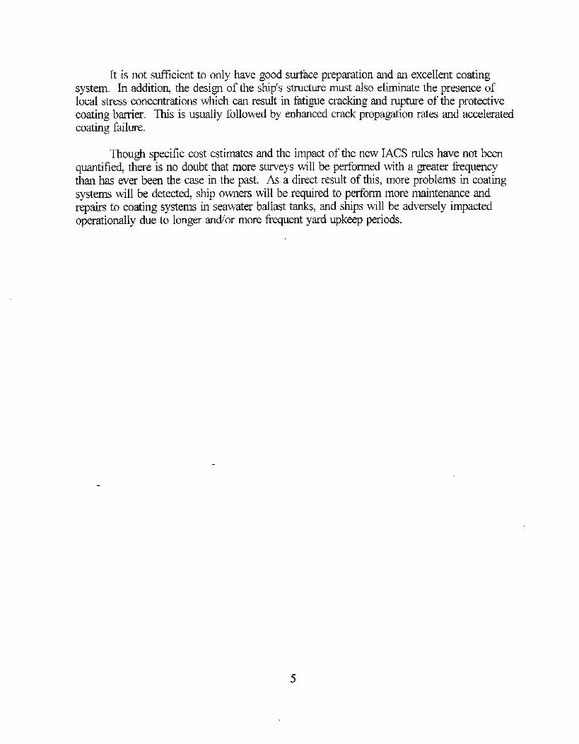
It is not sufllcient to only have good sudace preparation and an excellent coatingsystem. In addition, the design of the ship’s structure lmust also eliminate the presence oflocal stress concentrations which can result in fatigue cracking and rupture of the protectivecoating barrier. This is usually followed by enhanced crack propagation rates and acceleratedcoating failure.
~ough specific cost estimates and the impact of the new IACS rules have not beenquantifie~ there is no doubt that more. suweys will be performed with a greater frequencythan has ever been the case in the past. As a direct result of this, more problems in coatingsystems will be detecte~ ship owners will be required to perform more maintenance andrepairs to coating systems in seawater ballast tanks, and ships will be adversely impactedoperationally due to longer ardor more frequent yard upkeep periods.

(THIS PAGE INTENTIONALLY LEH BL4NK)

The fmt step in determining the
CHAPTER3
APPROACH
current commercial ship maintenance and repairpractices was to research the presewation practice followed by the major participants in theship repair business, namely shipyards, coating manufacture, and classification societies.This effort was conducted by visits to U.S., European, and Japanese shipyards, meetings withseveral coating manufacturers, and a review of the roles and regulations governing thepresemation of inter-hull spaces in double hull ships. Ship owners were not queried becauseit was assumed that the presewation practice executed by the shipymd would be the mosteconomical procedure the ship owner would approve while still maintaining certification bythe governing classification society.
Once this data was obtaine& the U.S. Navy’s new presemation protocol for tanks wasrefined in order to develop a proposed preservation protocol specifically for inter-hull spat=.Changes and refinements to the U.S. Navy tank presewation protocol were made based upona review of commercial presewation practices and input from coating manufacturerrepresentatives on the best available coating technology.
The guides were developed by consolidating the best coating presemation practices ofshipyards and procedures ad’or requirements imposed by the classification societies andthose recommended by coating manufacturers. Information from existing American Societyfor Testing and Materials (ASTM) standards and guides, coatings industry literature, andprevious research papers was used as reference material to establish the details of each guide.
-7

(lHIS PAGE INTENTIONALLY LEH BIANK)
CHAJnER4
VAPOR PHASE CORROSION INHIBI’IURS
Vapor Phase Corrosion Inhibitom (vPCIs), also known as Vapor Phase Inhibitors(VPIs) and Volatile Corrosion Inhibitom (VCIS), are corrosion inhibiting compounds whichare transported as vapors to the surface to be protected. Through interaction with existingcorrosion, oxidizd VPCIS in the fmt molecular layer neutralize the affected area. Anadditional VPCI film layer which forms above the oxidized VPCI molecules, repels moisture,oxyge~ and other corrosive agents. VPCIS, unlike traditional protection methods, overcomepermeability problems by working at the molecular level with an active barrier. VPCIS meusually used in enclosed spaces to protect metals or alloys from atmospheric corrosion.7
Many electrical systems have bare metal surfaces that cannot be treated withtraditional coatings. In these situations, VPCI emitters are particularly suitable-s VPCIS aretransported to the surface to be protected through vaporimtion. When the equilibrium vaporpressure is reache~ the vapors condense to form a crystalline structure on the surface to beprotected. The inhibitor layer is loosely bound to the metal surface by adsorption. However,the force of attraction is not strong enough to prevent the inhibitor fiorn leaving the surfaceupon removal from the inhibitor saturated environment.
If the inter-hull areas are to remain as voids, the use of VPCIS has limitations.’ VPCIShave been very successful in relatively small enclosures such as electrical connection boxes,switchboards, and load centers. Transferring this technology into void or inter-hull spaceswhich may be several hundred or thousand square meters in area has not been accomplishedand is not recommended until large-scale evaluations of VPCI capabilities are conducted. Inaddition, due to the intricate design of structural members and the need to evenly distributethe inhibitor concentration over all parts of the inter-hull are+ this will be difficult to achieveonboard ships at sea g Vendor data sheets indicate that the most promising VPCI willtypically protect bare steel surfaces born corrosion for two years.[o However, since inter-hullareas may be opened for periodic inspection at intervals shorter than every two years, theVPCI will have to be replenished more frequently than advertised. This is due to theirexposure to atmospheric corrosion products because of periodic openings.
If the inter-hull areas me to be used as ballast and me presewed with VPCIS,environmental considerations will prevent the pumping of contaminated water overboard(chromates, phosphates, etc.). Thk will severely restrict the operational configuration of theship.
The requirement for a continuous supply of inhibitor vapor for replenishment, the highcosts associated with replenishing VPCIS in large inter-hull spaces, and the potential use ofthe inter-hull space as a ballast tank illustrate the incompatibility of VPCIS as a corrosioncontrol method for the inter-hull areas of double hull ships. If however, the inter-hull spacewill be utilized as a @ void and will not be ballasted nor opened frequently, the use of
9

VPCIS in combination with a coating system may attain corrosion protection of greater thanten years.7
10
CHAPTER5
SPRAY METAL COATINGS
Thermal spray for corrosion protection is normally applied by either the wire flame(combustion) or wire arc process. The metal wire is fed into a gun and melted either by aflame (normally oxy-acetylene) or an electric ac. The atomized particles are propelled bymeans of compressed air onto the surface, where they cool, forming layers of splat-quenchedpmticles. W~e spray aluminum (WSA) or flame spray aluminum (FSA) are the most popularspray method coating. Coating systems with an aluminum base offer greater corrosionprotection and reduce shipboard maintenance. The application of a sealer or topcoat providesthe coated surface with long-term protection. These coatings also provide electrochemical(cathodic) protection, particularly during exposure to an aggressive marine atmosphere and inproximity to dissimilar metals.
Field tests were conducted in Norway on steel piles coated with aluminum thermalspray followed by a wash primer, a coal tar vinyl paint, and then a topcoat. After one year orless, in spite of the organic coatings, blisters appeared in the coatings on all the piles in thesplash zone. The failure analysis indicated that the ma;or contributing factor was inadequateadhesion between the steel and aluminum thermal spray coating due to poor surfacepreparation.11
For marine applications, thermal spray aluminum coatings are normally 180 to 250 pm(7 to 10 roils) thick in order to limit through porosity (too thin a coating) and to minimizethermal expansion mismatch (too thick a coating) with the substrate which would result inbonding separation. However, even with the inherent advantage of cathodic protection ofWSA or FSA compared to typical coating system such as epoxy, the use of metal sprayedcoatings for the inter-hull spaces of double hull ships is not feasible and is not recommended.This conclusion is based upon the following requirements for the “proper application of metalsprayed coatings:
● The substrate must be abrasive blasted to a white metal finish in accordance with SteelStructures Painting Council (SSPC) SP 5 standard. 12’3The surface, when viewed using amagnification often times, shall be free of oil, grease, dirt, visible mill scale, rust, corrosionproducts, oxides, paint, or other foreign matter. This requires that all prepared surfaces shallbe handled only with clean gloves, rags, slings, and so forth. If the substrate cannot becleaned such that all rust and oil are remove~ the thermal spray coating will not remainattached for long.
QDue to the corrllguration and size of the inter-hull areas, abrasive blasting must becompleted manually and not automatically.
● Metal spray operations have severe time constraints. Metal spray application shall bestarted within approximately 2 hours, and finished within 4 hours after anchor-tooth surface
11

preparation for steel has been completed. 15● Metal spray systems are much more complex than conventional paint systems. A metalspray system requires more component parts than a conventional paint system eachcomponent being more complex than its counterpart in a conventional paint system.
● Training and certificateion requirements for operators are much more detailed thanconventional painting operations.
● Metal spray coating application costs are approximately two and a half times the costassociated with using a conventional paint system. 11
Metal spray coatings do offer corrosion protection for other areas of the ship. Thiscorrosion protection method has been used for topside weather equipment, machine~ spaces,and interior wet spaces. Specifically, these categories include auxiliary exhaust stacks; dieselheaders; steam valves, piping, and traps: boiler skirts; stanchions, pipe hangers; riggingfittings; lighting fixtures; ladders; hatches and scuttles: boat davit machinery components;bilges; ad machine~ foundations. For marine atmospheric service, the use of thermal sprayaluminum coatings is an outstanding method of corrosion control.
12

CHAEqER6
PRESERVATION PROTKOL FOR THE INTER-HULL SPACE
In an effort to address and correct the costly corrosion problems occurring in U.S.Navy ships, the Naval Sea Systems Command (NAVSEA) and the Fleet Maintenance Offkersestablished a program. The pro~am is called Engineering for Reduced Maintenance, orERM This program has been in place since March 1993 with its emphasis on applying quickcorrective solutions to Fleet identified corrosion problems. One of the fmt problemsidentified by the Fleet was the frequent requirement to represewe tank coating systems duringperiodic maintenance cycles. Significant savings could be achieved by the U.S. Navy if theservice life of tank coatings could be increased by approximately three times to match theworldwide trend and extend the tank coating service life to 15 to 20 years.
To solve this problem, the U.S. Navy, specifically the Materials Engineering Group of -NAVSE~ sought to determine the tank presewation procedures of the shipbuilding industry,both nationally and internationally. After visits to shipyards and coatings manufacturers, andreviewing numerous new building specifications, classification socie~ guidelines andrecommendations, NAVSEA concluded that a 15 to 20 year service life could be achieved fortank coating systems. 79’14-1g To obtain this service life, NAVSEA developed a protocol basedupon the requirement that specific steps and procedures are essential during the surfacepreparation and coating application processes. This protocol was modified to specificallyaddress the environmental conditions expected in inter-hull spaces and includestechnologically improved coating systems recommended by the coating manufacture Theessential elements of the inter-hull preservation protocol are:
● Radius all edges, drain holes, coaming, hand holds, foot holds, laddem, etc. to a radius of 3m,
● Smooth welds and remove weld spatter;
● Reduce soluble salts on the substrate to less than 3 p~cm2;
c,Maintain relative humidity to 50°/0or less throughout the surface preparation and coatingappli~tion processes;
● Apply two coats of the light colore~ hi@ buil~ high solids epoxy coating system,
● Apply two stripe coats to areas not accessible to the paint spray gun; and to coating failuresusceptible areas such as edges, weld seams, pipe hangem, foot holds, etc. after the fmt fullcoat and prior to the topcoat.
Appendices Apresemation protocol.
and B provide the step-by-step procedure for the proposed inter-hull
13

6.1 Edge Radiusing
It is a well-known observation in the structures painting community that when acoating is applied to shwp edges, the coating will draw away from the sharp edge leaving itwith relatively poor coating coverage relative to the remaining flat surfaces. There is strongevidence that suggests radiusing or chamfering sharp edges will promote improved coatingperformance.
There are a significant number of references which suggest that edge rounding orchamfering to some degree. oilers a benefit of improved coating life. References include:
● National Association of Corrosion Engineers (NACE) Standard RPO178-9119recornmenckpractices for the desi~ fabricatio~ and surface finish of metal tanks that are to be coated forcorrosion resistance. These recommended practices are considered necessary by coatingsuppliem, applicators, and users of such tanks based upon experience. This NACE Standardstates that all sharp edges and weld fillets shall be ground to a smooth radius of at least 3.0mm with 6.0 mm prefened. ‘g
● DTRC Report 87/026,20 “Paint and Corrosion in SSN 688 Class Submarine Tanks”documents the inspection of’five submarines in d~y dock to determine if the lifetime of thetanks could be extended from 8 or 9 years to 15 years with touch up permitted every 3 years.The report noted significant metal loss due to corrosion obsewed along the stiffener edges intwo of the submarines inspected.
“ National Shipbuilding Research Program sponsored a study to investigate edge effects oncoating life in 198321and 1985.n Phase I of the study indicated no clear consensus of properedge preparatio~ rounding or chamfering.zl Grinding tools were not specified in any of thereported literature. Phase II of the study revealed that flat plate coating performance on 6mm (1/4”) thick plate requires a minimum 3.2 mm edge radius. For thicknesses 1=s than 6mm the relationship is the radius of the edge should be 0.5 times the thickness of the plate.For plates thickm than 6 ~ a limit of 3 mm (1/8”) should be imposed for edge rounding.The edge performance of the coating systems decreased with decreasing edge radius.z
● The SINTEF Group in 1993 recommended all sharp edges be rounded by grinding to aminimum rathls of 2 mm.9 Radiusing is performed prior to priming.
“ Det Norske Veritas Classification guidelines for corrosion protection of ships state all sharpedges on cut or burnt steel plates should be rounded or broken before blast cleaningoperations. ‘4 A minimum rounded edge is obtainable by means of a single pass of a grindingtool over the steel edge, breaking up a 90 degree or sharper edge into two, eachapproximately 90 + 45 = 135 degrees. Det Norske Veritas Classitlcation goes on to say thatrounding of sharp edges can also be specified more accurately by providing a minimumradius 14 No minimum radius is given in the Det Norske Veritas guideline.
14
● Lntheir specification for water ballast tanks, Nippon Kaiji Kyokai C1assNK recommendsthat a gas cut fi-ee edge be ground three times, thereby reducing the sharp 90 degree edge.t5
QHempel Paint in their analysis~ concluded that edges do cause a reduction in the Dry FilmThickness (DFT) of standard solvent borne epoxy coatings to edges. Hempel concludedrounding is more effective than breaking (chamfering) the edge and their data indicated that a2 mm radius is significantly more effective than a 1 mm radius. Hempel recommended edgesbe ground to a minimum 2 rnrn radius so that the specified film thickness can be built up.
● International Paint recommended that working procedures state that sharp edges or gas cutedges should be removed with a grinder or disc sander by breaking the edge three times.’6’24
● Jotun Protective Coatings’ A Guide to Ballast Tank Protection’7 recommends rounding ofsharp edges to a radius of 2 rnrn.
● Kvaerner Masa Yard and Danyard Shipyard in Europe utilize bulb tlats for structuralstiffeners thereby reducing the need to round edges.2~~h Both shipyards use disc grinders tomanually round those edges which require such a treatment.
● Two U.S. shipyards, Bath Iron Works and National Steel & Shipbuilding Co., smooth theedge with one pass typically by use of a disc grinder.272RAvondale Industries, Inc. ShipyardDivision “knocks” the edge off in 3 passes.2g
● Two Japanese shipyards, Narnura Shipbuilding Company, Ltd. and Sasebo Heavy IndustriesCompany, Ltd., break the edge with one pass using electric or air operated grinders.303’Maehata Shipbuilding Company, Ltd. rounds the edge to 2 to 3 mrn.~2
“ Korean shipyards smooth the free edge by grinding or stipulate that the free plate edge shallbe broken by grinding with a minimum radius of 1 mm.3~34
Cleady, the need to remove sharp edges is essential for avoiding the pullback of acoating system and subsequent thinning of the coating system along these edges. To ensurethe rounded edge is provided with a proper profile to accept the coating systerq the edgerounding step shall be pa-formed prior to abrasive blasting of the surface. The 2 rnrn radiusis concluded to be too small to enhance the performance of the coating along the edge. Inview of the literature cited above, all edges are recommended to be rounded to a minimumradius of 3 mm.
6.2 Weld Srnoolhing and Weld Sptter Removal
In the process of erecting steel structures and fabricating ship modules, hulls, and tankspaces, extensive welding must be performed. Welding techniques are varied. However, they
J include basic hand gas/arc welding as well as automated welding processes. Defects such as
15 —
weld spatter, weld undercuts, rough weld seams, and weld blowholes are inevitable by-products of the welding process. Good painting practice dictates that removal of weld spatterand grinding of rough weld seams be performed to provide a better surface for paintapplication as well as a higher expectation for ilmproved coating service life.’g’14’17719
The requirement for no skip welds, weld spatter, rough welds, gouges, undercuts, andother welding imperfections is clearly described in a number of references. This requirementis stated in most coating manufacturers guides for surface preparation, 1b.17’23’24’~5in Europeanshipyard surface preparation requirements,2J’2hin U.S. shipyard surface preparationrequirements,2s’2gin a Japanese shipyard surface preparation requirernent,30 in SINTEF’Srecommendations for pre-treatment of the steel member prior to painting,g and in a NACEstandard on the fabrication details for tanks for immersion service. ‘q This requirement hasrecently been included in a new coating rule by the International Maritime Organization(IMO).36
Clearly the need to remove weld spatter and weld defects is essential for optimizingthe performance of the coating system. In view of the literature cited above, it is imperativethat weld spatter be removed and that all weld defects such as gouges, undercuts, and surfaceirregularities be repaired prior to the application of the coating system.
6.3 Reduction of Soluble Salts
The type of water soluble salts on the steel substrate usually is indicative of thestorage conditions of the steel. Normally, sodium chloride, calcium carbonate, and ferroussulfate are present on the steel’s surface in varying concentrations and ionic combinations.These ionic species make up the bulk of soluble matter on the steel substrate. However, thereare other ionic species, such as zinc, potassium, magnesiw sulfide, and phosphate, which aregenerally found”in lower concentrations than the first group.
Surface contamination with chlorides has been shown to lead to rapid blistering oforganic coatings in immersion conditions. Wicks et al. discuss several theories in detail in“Organic Coatings, Volume 11’’.37The basic mechanism proposed relates to osmotic pressuredeveloped under the coating which acts as a semi-permeable membrane. This osmoticpressure causes some of the solvent from the more dilute solution to diffi.se through the semi-permeable membrane towards the more concentrated solution side to slowly dilute it.
This diffusion in one direction will continue until the two solutions have the sameconcentration or the more concentrated solution is pressurized enough to physically opposethe osmotic diffusion process. During the formation of coating blisters, osmosis causapressure to buildup at contamination sites. If this pressure exceeds the adhesion of thecoating, it lifts the coating at that point and forms a blister. The blister then continues togrow until equilibrium is reache~ either by solution dilution or a build up of pressure insidethe blister, to resist further flow into it. Such effects are often drastic when the immersion is
16

in distilled water which will promote osmotic blistering more so than sea water.38’39
It should be noted that not all blistering is caused by osmotic forces. Martinet ti.40relate blister formation to a defect controlled process in their “Non-Osmotic, DefectControlled Cathodic Disbandment of a Coating From a Steel Substrate”. Even in the absenceof osmosis-driven blistering, surface salt contamination may cr=te problems with corrosioncontrol. The corrosivity of any elwtrolyte that collects at the coatin@urface interface islikely proportional to its conductivity. Soluble salts on the surface would likely increase theconductivity and corrosivity of any local electrolyte.
Chlorides are generally considered to have the most significant effect on theperformance of coatings applied to metallic structures such as inter-hull spaces. In fact,theoretical and empirical evidence indicates that surface chlorides can cause premature failureof various coating systems. This research has been sponsored by many different organizationsin the U.S. and abroad.
The literature reviewed was generally from the marine, shipbuilding, and highwayindustries. The references most usefil for the maritime industry come from studies sponsoredby the Federal Highway Administration entitled “Effect of Surface Contaminants on CoatingLife”41and by the National Shipbuilding Research Program entitled “The Effects of SubstrateContaminants on the Life of Epoxy Coatings Submerged in Sea Water’’.~9
Various “ceiling” values have been determined for the maximum tolerable level forsurface chlorides. These values range from 0.6 p~cmz up to over 100 p~cm2. The reportedvalues differ depending on the test procedure of the researcher, the surface chloride extractionprocedure used during testing, the type of coating applie~ and the type of test exposure aftercoating application. However, most of the valuesqreported in the literature for epoxy coatingsfall in the range between 5 and 10 pg/cmz.q1b233~Jq
A threshold level of 3 p#cm2 is selected as the maximum level of surface saltcontamination for marine epoxy systems. This threshold level incorporates a safety factor oftwo for the lower end of reported values for chloride contamination. It has been readilyachieved by near-white metal blast cleaning (SSPC-SP 10), for the application of “~xy paintin U.S. Navy ship ballast tanks. ‘g-4245
6.4 Dehumidification
Manufacturer instructions and Naval Ships’ Technical Manual (NSTM) Chapter631%outline the environmental condition requirements during paint application that must be met tooptimize coating performance. For epoxies, unless manufacturer’s instructions state otherwise,it is essential that the substrate and surrounding temperature be between 2 and 35 degrees C(35 and 95 degrees F). NSTM Chapter631 further states that “paint should be applied onlywhen surfams are completely dry and surface temperature is at least 5 degrees F above the
17

dew point” and that the wind velocity should be less than 24 kilometers per hour (15 milesper hour) and the relative humidity less than 85’Y0.4(’
Research has shown that the corrosion rate of steel tends to accelerate at relativehumidities above 60?A.7232447Corrosion rates are correspondingly low at levels below 50% to60% relative humidity. If the environment inside the tank cannot b~ controlled such thatmoisture condensation on the steel smface is prevented, regmdless of ambient weatherconditions, then flash rusting can occur. The control of the interior environment to preventthis is possible an~ in fact, one can “hold” a blasted tank or inter-hull space indefinitely untilthe time at which the tank or inter-hull space is painted. This process is usuallyaccomplished by continuously forcing dehumidified air into all tank areas, thereby displacingany moisture-laden air. A dehumidified environment can prevent the onset of flash rusting.This saves costly sweep blasting and clean-up operations prior to painting.
Though most coating manufacturers recommend the relative humidity to be less than85!40during coating application, SIGMA Coating prefers the relative humidity to be below50Y$5, and International Paint prefers a level between 40?40and 60?A0.~4Danyard Shipyardlikewise establishes a relative humidity range between 25% and 60?@ and a French shipymdspecifies the relative humidity be less than 30°/0.1s
One National Shipbuilding Research Program (NSRP) reports9 emphasized that “thevery common practice of lowering the humidity to stop blasted steel surfaces from rapidlytig, does not correct the basic cause of the problelu it only hides it. Dehumidificationonly retards the flash rusting process temporarily”. Despite this finding, dehumidification isstill appropriate as an additional defense against flash rusting in the event surface chloridecontamination is not removed adequately born the steel substrate. This, however, should notbe the case for the inter-hull space since this preservation protocol specifically requires thesurface chloride contamination to be 3 p#cm2 or. less with a prescribed maximum level ofrelative humidky.
The relative humidity in the inter-hull space shall be maintained at 50% or less fromprior to abrasive blasting to final curing of the topcoat. This level of relative humidity is anadded safeguard to avoid the costly step of sweep blasting to remove ilash rusting of thesubstrate prior to coating application.
6.5 Tank (hating Mhterial
Before reviewing any coating system, it is important to understand that no coating canbe used or specified in any application for ship structure presemation in the United Statesunless it meets the Volatile Organic Compound (VOC) content regulations. To maintaincompliance, it is logical to consider the strictest set of VOC laws, namely the state ofCalifornia laws. These laws are expected to be adopted nationally by the EnvironmentalProtection Agency (EPA). The VOC content for all air-dried marine coatings applied after 1
— 18
September 1991 is 340 grams per liter. One notable exception is for Inorganic Zinc (IOZ)coatings which were permitted to have a 650 grams per liter limit until 1 September 1994, butare now also regulated to 340 grams per liter. Interestingly, 102 pre-construction primers arenot specifically addressed by the regulations as specialty coatings, and th~ impact of theregulations on these types of coatings is not clear. Based upon past experience, the maximumallowable VOC is regularly revised to lower limits and the above quoted limits are likely tobe reduced in the fhture.
In selecting a coating system for the inter-hull space, the following general guidelineswere followed:
● The protective system selected must be capable of meeting the requirements expected foruseful service life, fhture maintenance, and costs;
c Multi-coat treatments with coating layers of contrasting colors are recommended for betterconditions of application and a better final result;
● The final layer of paint should be light-colored to make it easily distinguishable fi-om rustand the onset of corrosion, and thus easier to inspect;
● Two-component products with long pot-life are preferable;
● The coating system selected for the protection of ballast tanks must be compatible with thedesigned and installed cathodic protection system (exposed to the maximum potential of thecathodic protection system for three months with no evidence of under cutting, peeling,blistering, or other coating system failure);
● Only products accompanied by detailed technical specifications and satisfacto~ performancerecords, and supported by appropriate test data should be used;
● The manufacturer of the coating system should be capable of providing adequate technicalservices throughout the surface preparation and painting evolutions.
With due consideration for VOC compliance, a proven track record of corrosionperformance, and a flash point of greater than 38 degrees C (100 degrees F), Hack et al.7
evaluated 28 commercial coatings. The majority of coatings evaluated were high solidepoxies, which is not surprising since they have been favorit= ~ong shipbuilders and s~Powners. Their results indicated that coating systems are currently available which initiallyappear to perform better than the standard Navy Formula 150/151 epoxy (MIL-P-24441).Yet, results of long-term exposure tests indicate that high solid epoxy coatings are theprefemed system for double hull application.48
A few technical references cite the epoxy-polyamide chemistry as the best performerof the epoxy type systems for water immersion service.~z4g-51The literatie data points to the
..- 19

following physical parameters of epoxy-polyamides as being important to their inherentexcellent performance in water immersion applications:
● Adhesion - In general, epoxy coatings demonstrate better adhesion to metal substrates thanmost other common generic marine coating types. The good adhesion shown by epoxiesderives fi-om the hydrogen bonds developed by their polar hydroxyl groups and their goodsurface wetting properties when properly formulated. Adhesion is a key performanceparameter for barrier coating systems since it directly affects the propensity for the coating todelaminate in the area surrounding defects.iz
● LOWWater/Ionic Permeabi Iity - Polyamide cured epoxies demonstrate excellent resistance topermeation by water and aqueous ions due to the high cross-link density of the cured film.This resistance tends to slow the migration of water molecules through the paint film andprevent the migration of potentially corrosive species fi-omthe seawater contained in the tankto the bare steel surface beneath the coating.s2
● Relative Surface Tolerance - The excellent wetting nature of epoxy-polyamide, the use ofwater displacing solvents, and existence of polar groups within epoxy-polyamide coatingsmakes them inherently more tolerant of minor amounts of surface moisture than coatings thatcure through a “drying” process. In addition, ahhou.gh performance of any coating is highlydependent upon surface cleanliness, the epoxy-polyamides will perform better on less-than-ideal surfaces than many other high performance type coatings. This quality provides apractical safety factor when applying coatings in the often less-than-ideal shipyardenvironment.52
● Durability - The highly cross-linked structure of epoxy-polyamide coatings make them moredurable and abrasion resistant compared to other generic types of marine coatings. Thisquality is important for immersed surfaces such as inter-hull spaces being used as sea waterballast tanks which operate in uncontrolled and unfiltered water.~~
For epo~-polyamide type coatings, laboratory studies have shown that thedeterioration rate of a coating in sewice is not linear with time. Data has shown that U.S.Navy approved epoxy-polyamide coatings’ rate of moisture absorption, as indicated bycapacitance measurements, is logarithmic with time. In other words, as the thickness of thepaint is doubl~ theoretically a ten-fold increase in the coating life can be expected. Though,in actual shipboard application, this may not be the case; it does seem reasonable to expect anextension in the life of the coating system if the coating system thickness is increased.Additionally, in barrier-type coatings, the thickness of the coating system has shown to be agood predictor of impending coating failure.
Also, Dr. Ingenior has shown that the rate of underfdm disbandment in short termtests is ‘inversely related to dry film thickness (DFT) for epoxy lype paints, with the ratebeing reduced by a factor of about three when the coating thickness is increased from about75 to 300 microns (3 to 12 mils).53 In the same work, it was shown that the ionic transfer
20

resistance (coating resistance) also reached a maximum afler exceeding a minimal dry filmthickness of about 100 microns (4 roils) for an epoxy coating. In addition, the Leidheiser andSINTEF reports of December 1992 both detailed that a minimum coating resistance isnemsary for the performance of the barrier coating.54”~sIn other words, there is a minimumrequired dry film thickness for the coating system to properly provide protection to the steelsubstite.
Wicks et a137suggest that maintenance coatings ought to be applied at thicknessesgreater than 400 microns (16 roils) to insure long life. If for no other reason, the greaterthickness and a two coat application reduces the chances for a coating defect to extendthroughout the coating thichess.b”’4’1jlS’~1
However, there is a signifimt conce~ for high build coating thicknesses of 250microns (1O roils) dry film thickness or greater. This concern is addressed by ensuring propercuring and avoiding runs, sags, and solvent entrapment. Excessive thickness, above thespecified amount, will usually degrade the performance of the coating, not enhance it.3b’5GAdequate ventilation and compliance with the manufacturer’s instructions should be followedto avoid any occurrence of solvent entrapment and improper curing of the coating system.This concern can be avoided by utilizing a 100VOsolids epoxy coating system.
Numerous coating manufacturers recommend the use of high solids epoxy coatings inseawater ballast tanks with solids content ranging from 80°/0to 10OO/O.‘b17’23’3>Additionally,both European shipyards visited and a French shipyards report documenting 15 years ofexperience in painting ballast tanks confhrn application of relatively high solid epoxy systemsin their ballast tanks. 18’2J12GIt is noteworthy that despite the added cost in some cases to usespecial equipment to apply 100°Aor near 100°Asolids coatings and the increased difflcuky toapply these coatings in confhed areas within the inter-hull ar~ ship owners and shipyardsstill continue to specifi these coating systems for the inter-hull space due to their superiorperformance. Other reports fi-om Europe confmn the use of epoxy systems in ballast tanks.b14The SINTEF report recommended for the best corrosion protection of ballast tanks, epoxy-
based systems in li@t colors be applied to blast-cleaned substrates.’) All U.S. shipyardsvisited also apply epoxy systems to their ballast and fuel tanks.27-z1]~7~sCoal tar epoxycoatings which are no longer authorized for use in the U.S. shipbuilding industry, are stillused and recommended by the Japanese shipbuilding industry.’5’30
In the pas~ an easy coating selection has been the use of soft coatings for themaintenance of ballast tanks in oldek vessels. However, these systems tend to hide problemsrather than cure them, and subsequent tank inspections will be extremely dangerous in viewof their slippeq nature, in particular the lanolin products applied in 500 to 1000 microns (20to 40 roils) DFT.
The compartments of ballast tanks are difi~cult, narrow are=, ~d li@ conditio~ Cmhave a significant impact on the standards of application. A black tar epoxy paint creates theworst possible condition as it “steals” light and the painter will have a diflicult time seeing

during the painting operation. Supemisors controlling the work and inspectom who mustinspect the ballast tanks will be hindered by the poor lighting condition. To prevent thisoccurrence, coating manufacturers”7 and Det Norske Veritas 14recommend the top coat of thecoating system be light colored to facilitate inspection of the coating application process andthe material condition of the coating system during future inspections. The use of lightcolored coatings also provides the added benefit of quicker inspection times, thereforereducing the time out-of-service for the vessel.
Another consideration in the selection of the-inter-hull space coating system is itscompatibility with the pre-construction primer used. In all cases, if the pre-constructionprimer is not compatible with the epoxy coating system, it shall be removed by abrasiveblasting to SSPC-SP-1O, near white metal. This requirement maybe waived when the coatingmanufacturer of the epoxy coating system recommends otherwise and acknowledges that therewill be no degradation in performance of the epoxy coating system. In this specific situatio~all markings on the pre-constmction primer shall be removed by abrasive blasting to”SSPC-SP-7, brush off blast clean, prior to the first coat of the epoxy coating system.
With due consideration for performance, thickness, e=e of inspectio~ ~d avoi~ceof solvent entrapment; a 100°4 solids light colored epoxy coating system of two coats, eachcoat at 250 microns (1O roils) @ film thickness, is recommended for the inter-hull space.
6.6 Edge S@e Coating
The necessity for stripe coating resides in the nature of the coating being applied.Apart from the many excellent characteristics of epoxy coatings, one of their shortcomings isthe lack of good edge coverage. This is because after the coating is applie~ there is atendency for it to pull away from the edge. This results in a much thinner coating along theedge and one that offers a reduced barrier coating for thk steel substrate. Since edge failureis the leading cause of tank coating failure, additional steps are required to resolve thisproblem. One step is the application of stripe coats along edges, welds, and diflicult-to-reach~em 7,9,l&lS,~-26,33-35,3g,50,59,60
The National Shipbuilding Research Program reports entitled “The Effect of EdgePreparation on Coating Life’’21’22discussed stripe coating and performed tests to derivequantitative da~ The results of the 229 day immersion and 60 day salt fog tests revealedthat stripe coating with a brush and airless spray performed worse than with airless sprayalone. Brush coated edges suffered from paint chipping due to excessive build up andinconsistent thicknesses. However, airless spray cannot be used on all locations. All spraymethods have an inherent disadvantage of not providing adequate coverage on the back sideof edges due to shadow effects.
The SINTEF Group reportg discusses the necessi~ to use only a brush for stripecoating. They recommend the application of the iirst stripe coat after the fmt coat of primer
22

has been applied over the tieshly blasted steel. The SINTEF Group specifically warnedagainst the use of a roller or spray as a means of applying the stripe coat.
Avondale Industries, Inc. Shipyard Division has had success with stripe coating usinghigh volume low pressure equipment. 29 National Steel & Shipbuilding Co. prefers to brushapply their stripe coats, rather than use either spray or high volume low pressure equipment.2*
In comparing stripe coating to radiusing, Hempel Paint Company concluded that astripe coat is especially beneficial over a sharp edge.2~ As the sharpness of the edgedecreases, the effectiveness of the stripe coat decreases to almost no added value.International Paint recommends the stripe coats be applied by brush or roller.24 Det NorskeVeritas Classification Society also recommends two stripe coats with brush be applied inballast tanks. 14 This application method is also endorsed by Deere.j’
The benefits of stripe coating to extend the service life of a tank coating system isclearly indicated in the literature. Based upon the literature cited above, a stripe coat shall beapplied to all edg=, welds, and difficult-to-reach areas for each coat of the coating systemspecified. However, the literature is not deftitive and is often conflicting on therecommended application method for striping. Therefore, for the presewation protocol for theinter-hull space, stripe coats shall be applied in accordance with the coating manufacturersrecommended method and be of contrasting color to the colors of the fmt and top coats.Depending on the size of the inter-hull space, the first stripe coat is recommended to beapplied after the fmt coat. The stripe coat associated with the top coat shall be applied priorto the application of the top coat. This is to ensure the tank or void is finished with oneuniform light colored coat of paint to enhance all visual inspection requirements. Allowsuficient drying time per the coating manufacturer’s instructions between all stipe coatapplimtions.
23
(THIS PAGE INTENTIONALLY LE17 BMNK)

Chapter 7
CATHODIC PRCWFXTJION
Cathodic protection is a method of protecting a metal surface from corrosion byopposing the electrical current flow that would naturally occur as part of the corrosionprocess. This is accomplished by use of either sacrificial anodes or impressed current. Bothsystems can be used in combination with coating systems to prevent or reduce corrosion.Sacrificial anodes are composed of relatively active metals that will preferentially corrode(sacrifice) and in the process protect the structural metal, usually steel. In theory, any metallisted in the galvanic series (see Table 7. 1) which is more electronegative (active) thananother may provide cathodic protection for the more electropositive (noble) metal. This isthe basis for marine sacrificial anode cathodic protection systems. Zinc and aluminum are themost common materials for sacrificial anodes used in cathodic protection systems designed toprotect steel structures and components in marine environments. Iron alloys are often used as‘modes to enhance the corrosion resistance of copper alloys.
TABLE 7.1 Galvanic Series of Metals
Cmmded M - Anodic or less noble (Eleclmnegative)
MagnesiumZincAhlrninumCadmiumLron or SteelStainlms Steels (active)Soft SoldersTinLeadNickelBrassBronzesNickel-Copper AlloyscopperStainless Steels (passive)Silver SolderSilverTitaniumGoldPlatinum
Protected End - Cathodic or most noble (Electmpxitive)
25.—
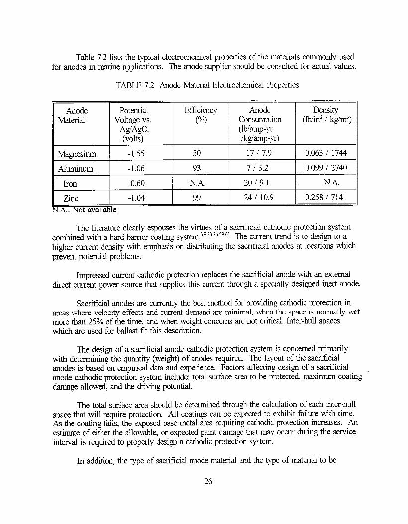
Table 7.2 lists the typical electrochemical properties of the materials commonly usedfor anodes in marine applications. The anode supplier should be consulted for actual values.
TABLE 7.2 Anode Material Electrochemical Properties
Anode Potential EfficiencyMaterial Voltage vs. (%)
A~AgCl(volts)
Ziic -1.04 99
A - Not avadable..
Anode DensityConsumption (lb/in3 / kglm3)(Ibhnp-yrlk~amp-yr)
17 I 7.9 0.063 / 1744
7 I 3.2 I 0.09912740
=--t==
The literature clearly es~ouses the virtues of a sacrificial cathodic protection system,.combined with a hard barrier coating system.s’g2ssb”s(~b]ne current trend ~Sto desi~-to ahigher current density with emphasis on distributing the sacrificial anodes at locations whichpr~vent potential problems.
Impressed current cathodic protection replaces the sacrificial anode with an externaldirect current power source that supplies this current through a specially designed inert anode.
Sacrificial anodes are currently the best method for providing cathodic protection inareas where veloci~ effects and current demand are minimal, when the space is normally wetmore than 25°/0 of the time, and when weight concerns are not critical. Inter-hull spaceswhich are used for ballast fit this description.
The design of a sacrificial anode cathodic protection system is concerned primarilyrrnining the quantity (wei@) of anodes required. The layout of the sacrificialwith dete
anodes is based on empirical data and experience. Factors affecting design of a sacrificialanode cathodic protection system include: total surtace area to be protected maximum coatingdarnage allow@ and the driving potential.
The total surface mea should be determined through the calculation of each inter-hullspace that will require protection. All coatings can be expected to exhibit failure with time.As the coating fails, the exposed base metal mea requiring cathodic protection incraes. Anestimate of either the allowable, or expected paint damage that may occur during the serviceinterval is required to properly design a cathodic protection system.
In additio~ the type of sacrificial anode material and the type of material to be
26-
protected are determined. In most cases for inter-hull spaces,anodes are selected for the steel substrate.
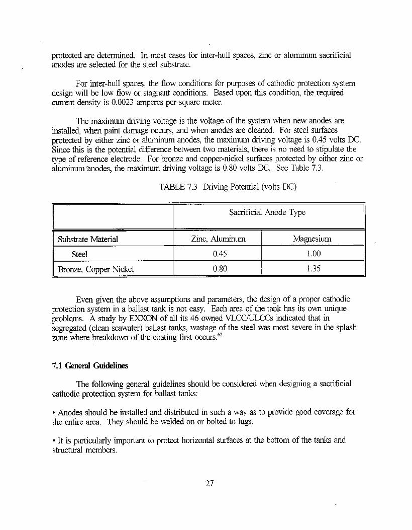
For inter-hull spacm, the flow conditions for purposes
zinc or aluminum sacrificial
of cathodic protection systemdesign will be low flow or stagnant conditions. Based upon this conditio~, the requiredcurrent density is 0.0023 amperes per square meter.
The maximum driving voltage is the voltage of the system when new anodes areinstalle~ when paint darnage occurs, and when anodes are cleaned. For steel surfacesprotected by either zinc or aluminum anodes, the maximum driving voltage is 0.45 volts DC.Since this is the potential difference between two materials, there is no need to stipulate thetype of reference electrode. For bronze and copper-nickel surfaces protected by either zinc oraluminum ‘anodes, the maximum driving voltage is 0.80 volts DC. See Table 7.3.
TABLE 7.3 Driving Potential (volts DC)
Sacrificial Anode Type
Substrate Material Zinc, Aluminum MagnesiumI I I
Steel 0.45 1.00
Bronze, Copper Nickel 0.80 1.35
Even given the above assumptions and parameters, the design of a proper cathodicprotection system in a ballast tank is not easy. Each area of the tank has its own uniqueproblems. A study by E=ON of all its 46 owqed VLCC/ULCCs indicated that insegregated (clean seawater) ballast tanks, wastage of the steel was most severe in the splashzone where breakdow of the coating first occurs.L2
7.1 Geneml Guidelines
The following general guidelines should be considered when designing a sacrificialcathodic protection system for ballast tanks:
● Anodes should be installed and distributed in such a way as to provide good coverage forthe entire area. They should be welded on or bolted to lugs.
● It is particularly important to protect horizontal surfaces at the bottom of the tanks andstructural members.
27

● h anode will normally protect surfaces in direct “line of sight”. Surtaces behind stiffene~,around comers, and inside pipes will not be adequately protected.
● Sacrificial anode cathodic protection is effective for tanks that are continuously ortiequently immersed in water. The parts of the tanks not submerge~ such as the top of thetanks, are not protected by the cathodic protection system. .
“ Tank bottoms which contain standing water are particularly liable to suffer fi”ompitting. Inthese areas, anodes should be installd on the bottolm of the tank.
“ Locate anodes in such a way that they can be easily washed down to remove sludge andother deposits.
● For tanks with a large number of small sections and compartments, install at least one anodein each small compartment.
● Aluminum anodes deliver more current per unit weight than zinc and therefore are a betterchoice in financial terms.
7.2 Design Melkkdogy
The design methodology calculates the minimum number of anodes require~ using thefollowing steps:
● Calculate the required current for cathodic protection using surface are% percent paintdamage, and required current density.
“ Calculate the amps per anode based on driving voltage and anode type.
● Calculate the number of anodes required.
To calculate the required current for cathodic protection using the surface ar~ percentpaint damage, and required current density, use the following equation:
where IR~uiE~= current required for cathodic protect ion
irequired = current density required for cathodic protection (amps/area) per Table 7.4
S~O,~= total surface area to be protected
Percent Paint Damage = allowable paint damage as a percentage of the total surface area
28
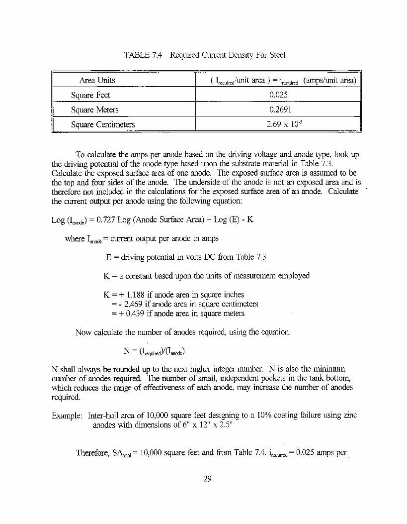
TABLE 7.4 Required Current Density For Steel
Square Feet 0.025
Squme Meters 0.2691
Square Centimeters 2.69 x 10-fI
To calculate the amps per anode based on the driving voltage and anode type, lookupthe driving potential of the anode type based upon the substrate material in Table 7.3.Calculate the exposed sudace area of one anode. The exposed surface area is assumed to bethe top and four sides of the anode. The underside of the anode is not an exposed area and istherefore not included in the calculations for the exposed surface area of an anode. Calculate ‘the current output per anode using the following equation:
bg (1~~~)= 0.727 Log (Anode Surface Area) + Log (E) - K
where I~A = current output per anode in amps
E = driving potential in volts DC born Table 7.3
K = a constant based upon the units of measurement employed
K = + 1.188 if anode mea in square inches= -2.469 if anode area in square centimeters= + 0.439 if anode area in square meters
Now calculate the number of anodes required, using the equation:
N shall always be rounded up to the next higher integer number. N is also the minimumnumber of anodes required. The number of small, independent pockets in the tank bottomwhich reduces the range of effectiveness of each anode, may increase the number of anodesrequired.
Example: Inter-hull area of 10,000 square feet designing to a 10% coating failure using zincanodes with dimensions of 6“ x 12” x 2.5”
Therefore, S~O,,l= 10,000 square feet and horn Table 7.4, i,@~,ti,,~= 0.025 amps per,
29

square feet.
Calculate IR~,ti,,~= (10,000)(0.10)(0.025)
Anode Surface Area =(6 x 12)+ 2(6 x 2.5)+ 2(12 x 2.5)= 162 square inches
NOTE: The sutiace of the sacrificial anode in tight contact with the substrate is notincluded in the effective anode surface area calculation.
The driving potential for a zinc anode on a steel substrate from Table 7.3 is 0,45 voltsDC and K is 1.188 if the anode area is in square inches.
Therefore,Log (I~tiC)= 0.727 Log (162)+ Log (0.45) - (1.183)
Log (L,,O,J= 0.0715
I~,,~e= 1.179 amps
Calculating N = (25)/(1.179)
N = 21.2 and rourdhg up,
N =22 anodes
7.3 In-Sem_ice Inspction
The protection potential of a cathodic protection system can be measured in a tank bylowering a standard reference electrode which is connected to a voltmeter and reading thepotential difference between the reference electrode and the adjacent steel surfaces. This willrequire the tank to be full of seawater. The potential gives a value which represents anaverage protection for the tank. This may make it difficult to assess if some local areas arewell protected and others are not. However, these potential measurements provide importantindications of the condition of the tank.
Several types of reference electrodes may be used. The reference electrode isconnected to the negative contact of a DC millivoltrneter with an input impedance of about104 ~ No current should pass through the reference electrode. The positive contact isconnected to the steel (i.e. at the top of the tank where measurements are being made). Thereference electrode is moved to a number of positions, but not near a sacrificial anode. These
30

measurements should be conducted while the vessel is in operation in order to be able tofollow up how its condition changes with time.
When the tank is empty, check the anodes and determine if they are being consumedor whether they have been passivated. An even distribution of calcareous deposits indicatesthat the cathodic protection system is working well. Zones lacking deposits are normallyindicative of insufficient protection.
7.4 Sem-ice Iife
The service life of sacrificial anodes is dependent primarily on current output of theanode and mass of the anode. Current output, in turn, is dependent on the amount of baremetal being protecte~ electrolyte resist ivity, velocity, and temperature.
Traditional application of anode consumption rates are based upon assumed currentdemand and driving potential. This assumption is adequate for anode service life up to 6 to 7year-s. Prediction of anode service beyond 7 years is not considered reliable. Therefore,periodic inspection andlor monitoring is required beyond 7 years of service life.
31

(THIS PAGE INTENTIONALLY LEH BIANK)
CHAPTERS
SURFACE CIXMMINATtON DETECTION
Soluble salts on steel substrates cause premature coating failure.~7’~gIt is important forthe ship owner, shipyard and coating manufacturer representatives to ensure the steelsubstrate is not contaminated with surface salts. The types of water soluble salts found on asteel surface reflect the environment in which the steel has been stored. Normally, sodiumchloride, calcium carbonate, and ferrous sulfate are present on the metal’s surface in varyingconcentrations and ionic combinations.
By knowing the quantitative amount of surface salts on the substrate, appropriateaction can by taken by the shipyard to ensure the measured surface salt concentration isbelow an agreed threshold level. Conductimetric measurement with results expressed inmicrosiemens per centimeter (pS/cm), can be a valuable tool for determining saltconcentrations .63
The Bresle Test procedure is recommended for its portability and ease of use. Theprocedure outlined below combines the results of three references”’b3~ and requires a BresleKit (available from KTA-Tator, Inc. in Pittsburgh, PA), an electronic conductivity meter, anda thermometer. The Bresle Kit is available in a carrying case and is ideally suited for fieldmeasurements. Briefly state~ the procedure to determine the chloride concentration of thesteel substrate in micrograms per square centimeter (p~cm2) is:
1. Determine a suitable surface for the test. The surface maybe horizontal, vertical, slanting,or somewhat bulging. The surface should be relatively dry without any noticeable dampness.
2. Take one Bresle Sampler ( 12.5 cm2) from the equipment case, remove the filler of itscompartment and the protective paper label. Press the Bresle Samplefs adhesive side onto theselected test surface. Best results are achieved when the surface temperature is above 10degrees C (50 degrees F).
3. Insert an empty syringe into the cell via the spongy foam perimeter. Evacuate the air fi-omthe cell using the syringe. Bend the syringe needle as required.
4. Insert 10 ml of distilled water with the syringe through the spongy foam perimeter. Holdthe perimeter of the cell firmly to avoid leakage of the distilled water.
5. Gently rub the top of the cell to agitate the distilled water in the cell to remove any surfacesalts and to place the salts into solution with the distilled water. Avoid excessive rubbing toprevent leakage of the liquid from the sampler.
6. After approximatelythen reinject the liquid
15 seconds of agitation, remove the 10 mL of liquid with the syringe,into the sampling compartment and then suction the liquid back into
33

the syringe cylinder. Repeat until at least four cycles of injection and sucking back into thesyringe have been completed.
7. At the end of the last cycle, remove and transfer as much as possible of the 10 rnL liquidfrom the sampling compartment to a clean plastic container provided. If leakage occurs fromthe sampler, the sample obtained shall be rejected.
8. ARer sampling, clean and rinse the syringe so that it can be re-u.sed. A bent needle is bestleft m it is until it becomes necessay to straighten it or “bendit fhrther.
9. Measure the conductivity of the liquid in microsiemens usingmeter.
an electronic conductivity
10. Measure the temperature of the liquid using a thermometer.
11. Correct the conductivity measurement of the liquid for temperature by using the values of “Table 8.1 and the forrnulZ-
(Conductivity Reading) x (Correction Factor)
TABLE 8.1 Temperature Correction
Temperature of Liquid Correction Factor(degrees C)
15.0 1,10
17.5 1.05
20.0 1.00
II 22.5 I 0.95
25.0 0.90
12. Calculate the concentration of chlorid= in m#L by using the following relationship:
Concentration in m~L = K x (Conductivity)
Where K = 0.43 (the average value for sodium calci~ and ferrous chlorides)
13. Calculate the weight of salt in mg in the 10 rnL of extracted liquid by multiplying thecalculated concentration in mm by the 10 mL volume, and dividing by 1000 (rnUL).
34

14. Calculate the concentration of chlorides in p~cm~ by dividing the weight of the salt in mgby the area of the patch (12.5 ctn2) and multiplying by 1000 (y~mg).
15. For compariso~ calculate the concentration of chlorides in p~cm~ of 10 mL of distilledwater by repeating Steps 9 through 14 above.
EXAMPLE: Conductivity meter reading is 5 @.Temperature of the liquid is 25 ‘)C.Volume of the sample is 10 mL.
a- Concentration in rn#L is calculated to be:
0.43 x 5 x 0.90= 1.94 m#L
b. Weight of salt mg in the 10 mL of liquid is calculated to be:
(1.94 x 10)/1000= 0.0194 mg
c. Concentration of chlorides in pg/cm~ is calculated to be:
(0.0194 x 1000)/12.5 = 1.55 @cm2
35

(IHIS PAGE INTENTIONALLY LEH BUNK)

CHAITER9
EDGE PROTECTION SYSTldMS
The requirement for portable edge rounding tools is necessary because the U.S.shipbuilding industry practice is to use shapes which normally come with sharp edges. Fromobse~ations and interviews with commercial shipyards. it is apparent that edge rounding orchamfering is accomplished manually by the use of IOWpressure air and electric disc sandersor grinders 25-32It seemed apparent that the shipyards visited were not interested in improvingtheir efficiency by designing a tool to accomplish the edge rounding requirement. Forconfined or hard-to-reach areas, the use of smaller hi@ speed die grinders with variousattachments to fit the task at hand are recommended. The U.S. Navy is developing an edgerounding tool which will be able to round both edges of a stiffener in one pass. Shipboardevaluation of this edge rounding tool is expected in fiscal year 1996.
AS previously reportei all edge rounding operations now are mechanically performedby shipyard workers grinding the sharp edge until a smooth surface is obtained. Research hascommenced to evaluate edge protection systems, in lieu of manually rounding the edgeswhich can be applied to the edge tier the tank coating system has been installed. Thisevaluation has been initiated to investigate processes and materials which can offset therelatively high cost associated with manually roundingkadiusing edges. One concept beinginvestigated by the U.S. Navy involves the use of an easy to apply durable coating which isproposed to be applied along these sharp edges. Attributes of this edge coating systeminclude: no additional surface preparation on the edge; easy application; cure time amenablewith the tank coating system, excellent breakdown resistance; producible; and reasonablypriced.
Initially, tapes were investigated as a potential edge coating system. The concept wasto apply the tape along the edge thereby “smoothing” the sharp edge. Several U.S. tapemanufacturers were contacte~ and their recommendations were evaluated. The technicalevaluation concluded that tapes are not suitable as an edge protection system due toapplimtion difficulties, inadeqwte durability of the tape adlmive to tolerate the adverseservice conditions, and the increased potential for under-cutting and crevice corrosion alongthe tape’s edge.
Based upon the lessons learned in the tape evaluatio~ the U.S. Navy recentlycommenced evaluating the use of mastics, polysulfides. and an epoxy coating system as edgecoating systems. The use of mastics and polysulfides is recommended for evaluation basedupon the Navy’s success in the use of these products in other applications. The selection ofthe epoxy coating system is based upon the coating manufacturer’s product information whichadvertised the ability to provide good edge covering capacity. Limited laborato~ testing bythe U.S. Navy confirms the coating manufacturer’s claims of good edge coveringcharacteristic of this epoxy coating system.
I
37


(mAFTER 10
SENSORS
One method for observing and/or detecting corrosion on ships is by the use of sensors.These are especially usefhl in areas of restricted or limited access such m the inter-hull space.For inter-hull spaces, sensors can be used to study the onset and rate of corrosion as well ascoating breakdown.
All ships stier from the problems of corrosion. For the inter-hull spacing of doublehull ships, wtich is not always accessible nor monitored regularly, a remote method for
monitoring corrosion is desirable. Sensors can be used to oversee this area of the ship, todetermine the inception and rate of corrosion. Sensors offer unique advantages in terms of insitu sensitivi~, small size, and be used to monitor corrosion in environments that have limitedaccess.”
Electrochemical sensors make it possible to follow continuously the response of metalsto the chahges in atmospheric conditions. Such sensors are often constructed as galvaniccouples, such as copper/steel, which have the advantage that the galvanic current is easilymonitored and no e~ernal si~al needs to be applied.ti
Tkachenko’7 has studied the use of measuring corrosion rates by a method based onthe recording of currents occurring in a multi-electrode galvanic system composed ofelectrodes of the same type. This method is based on measurements of the currents in aTomashov multielectrode sensor, which is an assembly of alternating electrodes of twodifferent metals. Through prior research, Tkachenko concluded that determining theinstantaneous corrosion rate can be accomplished.
Sensors have been used to examine corrosion in various materials and environments.They have been used to study the effect of hydrogen in steels, including pipeline steels in
“69 Two main w of sensors, amperometncsour gas service. “ ‘s and Potentiometric, bg”gwerefound to be responsive to hydrogen in steel. The amperometric sensor measures the flux ofhydrogen through the steel, from which the hydrogen concen~tion at the inner stiace of thesteel may be drnated. The potentiometric sensor measures the equivalent pressure ofhydrogen in the steel.‘g These sensors can be attached to the external surface of the pipelineto specifically monitor the effects of the hydrogen in steel.
Sensors for the monitoring of corrosion of steel in concrete have been developed.’” Ifthe corrosion risk for the steel reinforcement is detected early enou~ damage can be avoidedor significantly reduced through relatively simple protection measures. For this reaso~ apermanent corrosion monitoring system has been developed which indicates the corrosion riskfor the reinforcement in concrete structures.
One company in Germany has developed a corrosion monitoring system which has
— 39

already been installed into three concrete structures:
● Schiessber@asse Bridge near Cologne, Germany● A bridge near Notsch, Austria● E,astern Railway Tunnel of the Great Belt Link Denmark70
Corrosion sensors have also been applied to aircraft.7’-74 Wyman reports that Stropkihas coupled these to credit-card sized monitors which provide an early warning of problems.71Such corrosion monitoring sensors have been tested on U.S. Air Force aircraft.” The systemmonitors the increase of electrical resistivity in small sensors as the material is corrodedaway, the thinner the material, the higher the resistance. The important factor is the rate ofchange.
This sensor system is applicable for use in double hull ships. It is hard wire~ but canbe connected dkectly to a computer onboard the ship. A typical sensor is 250 micronsthick.7t It is made of the same material and subjected to the same manufacturing treatments ‘as the structure being monitored. Each sensor is mounted on a glass probe and has anassociated reference sensor sealed in glass.
Agarwala reports that some electrochemical galvanic sensors have been successfullyused in salt spray chambers and humidity charnbers.7z Meanwhile, Goldfine has been lookingat nondestructive inspection techniques, such as ultrasonic and eddy current, and feels thatthese do not adequately detect the early stages of hidden corrosion under paint in criticalstructures such as air frames; therefore he has looked at Meandering Winding Magnetometers(MWMS) and Interdigital Electrode Dielectrometers (IDEDs).73 Additionally, Koch reports onnew developments, in addition to existing systems, for monitoring corrosion in aircraft.74
Two main types of monitors are linear polarization resistance and electrical resistivity.Since the system being studied will not be immersed at all times, linear polarization resistancemonitoring sensors cannot be used. Electrical resistivi~ monitors are more applicable. Theymeasure the electrical resistivity of the metal being monitored. The amount of change inresistivity is used to determine the rate of corrosion. The resistivity increases as the thicknessof the metal decreases. (This decrease in thickness is caused by the metal corroding away.)
There are a few companies which design and sell corrosion monitoring systems.Although not d=igned as remote monitoring sensors for double hull ships, some of thesesystems may be applied to the ship’s inter-hull areas. A wireless survey system with adigitti analog reader transmitter or DART maybe applicable. This device collects surveydata from three voltage inputs and transmits the information to a laptop and receiver locatednearby. 75 The system is designed to provide “hands off’ operation. Other systems utilize acompletely self-contained data logger for electrical resistance type probes. The frequency ofdata collection points determines the fi-equency of downloading of data. The more frequentthe collection of da@ the more frequent the data logger must be dowrdoaded.7b
40

CHAPTER 11
GUIDES
The guides were developed to assist in the presewation of inter-hull spaces. They areincluded in this report as Appendices C through F. Each guide was developed from a widespectrum of reference material. Existing ASTM Guides and Standards which dealt withsimilar issues were reviewed for applicability and provided excellent examples of content andscope. Recommendations tiorn coating manufacturer representatives and their work practiceinstructions for coating ship’s ballast tanks and voids were reviewed and collated. Shipyardpersonnel were interviewed and their comments and recommendations for the presemation ofballast tanks and voids were compared to each other and to the recommendations of thecoating manufacturers.
Similar to the development of the proposed inter-hull space preservation protocol, thedevelopment of the guides attempts to select those attributes from all the references whichwere concluded to be essential for providing a presewation system with a 20 year service lifefor the inter-hull space. Cost information and estimating procedures were obtained from twoarticl= which dealt exclusively on coatings and their associated costs.77”7g
In the development of the inspection guide, it is important to realize that each of themajor players views the inspection requirements and results differently. The ship owner isconcerned about safety and the costs of out-of-service time, maintenance, and repairs. Thelevel of detail of the inspection depends on whether the material condition assessment is usedto plan for routine maintenance of the corrosion protection syste~ identifj major problemswhich will require immediate corrective action, plan a major upgrade, meet the demands ofthe classification societies or authorities with interest in the sale or lay up of the vessel ormeet other requirements. On the other hand, the authorities and classification societies areprimarily interested in stiety, strength and loss of strength in structures and sub-structures andthe material condition results establish whether the vessel will require special, interim adorannual inspections.
However, the research consistently identified that the skgle most important ingredientfor success in attaining a 20 year preservation system rests with the individuals doing theblasting and painting. Even with clear and precise guidance, a durable and excellent paintsysterq and the best environmental conditions, it is”imperative that the blaster and painterunderstand the importance of their roles in the coating evolution and perform their jobscorrectly. Otherwise, the presewation protocol described in Appendices A and B is doomedto fail. It is msential that these two groups of workers are trained properly and are cognizantof their important roles.
41

(THISPAGE INTENTIONALLY LE17 BUNK)
CHAFK&R 12
CONCLUSIONS
QThe presemation of the inter-hull space is a major concern for all participants, includingship owners, classification societies, coating manufacturers, and shipyards.
● The material condition of the inter-hull space and “consequence analysis” determine whichpresemation protocol is “most suitable”.
● The best corrosion protection system for the inter-hul1 area combines a sacrificial cathodicprotection system wifi a hard b~er coating system.
● A cathodic protection system can be designed for the inter-hull area in such a way thatcompatible with a coating system.
● A coating presemation protocol for the inter-hull area is provided which is expected toprovide a 15 to 20 yea service life.
it is
● Metal spray coating systems are not practical for corrosion protection of the inter-hull areadue to poor production rates, high cost, specialized equipmen~ and increased operator trainingrequirements.
● Vapor phase inhibitors are not recommended for the inter-hull area due to theincompatibility of the inhibitor when the inter-hull space is used as a ballast tank.
“ The steel substrate of the inter-hull area should be tested to determine the level of chloridecontamination. The Bresle Test Kit with an electronic conductivity meter can quickly providemeasurements of the chloride contamination of the steel substrate.
● No single tool can perform all edge roundingkadiusing in the inter-hull space. Seven inchor nine inch disc sanders or grinders with 24 grit aluminum oxide abrasive pads are best forstraight runs. Smaller high speed die grinders with various attachments (i.e., flame shapedcarbide burrs, concave radius deburring heat or conical stone tips) are best for hard to reachareas. Mastics, Polysulfida, and an epoxy coating system specifically formulated for edgecovering capacity show initial promise as edge protection systems.
● Sensors which measure the change of the substrate’s electriml resistivity are recommendedfor the inter-hull space. Hard wired and wireless systems designed for other us= can beadapted to the inter-hull space.
43

(THIS PAGE INTENTIONALLY LEIT BLANK)

CHAPTER 13
PROIIMID STUDIES
Future studies are proposed for the following subjects:
1. Evaluate the feasibility and effectiveness of using alternative methods (mastic, high buildepoxies, cau~ etc.) for edge roundingkadiusing .
As described in Section 6.1, edge radiusing is utilized to prevent the pull back of thecoating system from the sharp edge. This results in a thinner layer of coating along the edgerelative to the remaining flat surfaces. However, cost analysis42’43conducted by the U.S.Navy indicate the procedure to round sharp edges by pneumatic grinders is extremely costlyand adversely impacts on the number of tanks which can be overhauled during a givenavailability. Despite this high cost shipyards25-34continue to manually round edges with disc .grinders. The need to reduce this cost burden by the shipbuilder or ship repair facility isessential for each to remain competitive and cost efficient. Other industries have also facedthe problem to smooth rough surfaces or leading edges. namely the automotive and airlineindustries. Mastics and caulks, with specially designed application equipment have been usedto smooth damaged or rough edges or surfaces. Also, coating manufacturers in response tothe need to smooth edges in ballast tanks, have commenced development of a new specialtycoating system which demonstrat~ the ability to retain a high film build on sharp edges.These alternative methods to smooth edges are promising, but Laboratory and in-service testshave not been performed.
It is recommended that a test program be developed approve~ and executed toevaluate these alternative methods for edge rounding. The program should identify the mostpromising alternative methods through product literature search and manufacturer’s testing andin-service documentation. Once this selection is made, laboratory screening evaluations isrecommended. These evaluations should include accelerated testing of the products inconditions expected in the inter-hull space. Evaluation parameters should includepetiorrnancs (durability, sag’resistance, etc.), productivity (ease of application), compatibilitywith the tank coating system time to set, surface preparation requirements, and cost. Afterthe laboratory screening tests, in-service tests in a simulated inter-hull space of the mostpromising products are recommended. In all evaluations, the products should be evaluatedagainst the control of manually rounding edges by disc grindem.
2. Evaluate the feasibility of electriml resistivity monitors as corrosion sensors in the inter-hull spaces of double hull design ships.
Remote sensors, although not currently use~ area faible option for monitoring thecorrosion of inter-hull spaces in double hull ships. -Electrical resistivity sensors work in bothwet and dry environments, whereas most other types of sensors must ‘remain immersed tofbnction properly. After a literature search on sensors and a survey of companies, there are
45

several companies capable of providing sensors usable for this application. Since no companycurrently designs sensors for this specific application, each must modify their candidatesensor(s) to suit the application requirements.
It is recommended that a test program be developed approved, and executed toevaluate the performance of each candidate sensor in a laborato~ and in full scale tests.Accelerated laboratory screening evaluations are recommended. These evalmtions shouldinclude testing of the sensors in conditions expected to be encountered in the inter-hull space,namely alternate immersion service with typical wet and dry time ratios between 80/20 and20/80. However, the alternate immersion cycles will be an order of magnitude more frequentthan what is normally experienced onboard ship. Evaluation parameters should includedurability, ease of installation, accuracy, and cost. After the laboratory screening tests, in-smice tests in a full scale model of an inter-hull space of the most promising sensom arerecommended. For the full scale model evaluations, the sensors should be evaluated using thesame parameters as the laboratory screening evaluations.
3. Validate the inter-hull area presemation protocol in double hull design ships,
Validation of the recommended preservation protocol presented in report is a logicalfollow-up to this project. It is recommended that a test program be develope~ approve~ andexecuted to evaluate the recommended preservation protocol against existing presemationpractices for the inter-hull space in terms of performance and life cycle cost.
The test program should identify several existing presemation practices for the inter-hull space, ~d conduct both laborato~ screening and in-service testing of the VtiOUS
presewation practices. As in all testing, the performance attributes to evaluate eachpresewation practice is important. Since Appendix D was developed to assist in theinspection of the coating system of inter-hull spaces, it is recommended the attributes listed inParagraph V of Figure 1 of Appendix D be used to evaluate the performance of eachpresewation practice.
46
IwFERINm
1. Shell International tie: “Corrosion Protection Systems for Newbuild Tankers” TankerStructure Cooperative Fen-q Oct 92.
2, American Bureau of Shipping “Double Hull Tank Vessels”, Sep 91.
3. American Bureau of Shipping’’Tanker Structure Cooperative Forum Project 102 FactorsContributing to Corrosion”, Jun 85.
4. Norwegian Maritime Directorate: “Coating Requirements of Ballast Tanks”.
5. 13enoit, J., “Preventhg Corrosion of Dedicated water Ballast Tanks on All Ships, andCargo Holds on Bulk Carriers; Prospects for Current and Future Classification Society Rulesand International Regulations”, RINA International Conference on Marine CorrosionPrevention, Oct 94.
6. Towers, R H., “Impact of New Rules on Structural Protection in Ships”, RINAInternational Conference on Marine Corrosion Prevention, Ott 94.
7. Hack H. et d., “Corrosion Control of Advanced Double Hull Combatants”, The AdvancedDouble-Hull Technical Symposium Ott 94.
8. Smi~ C. and Wlebusch, B., “The Next Level of Corrosion Control”, Erwineer’s Digest,Feb 95.
9. “Corrosion Protection of Tanks and Cargo Holds”, MARINTE~ The SINTEF Group, Sep93.
10. Cortec Product Data Sheet for VCI-307 and VCI-309.
11. Metals Handbook Ninth Edition, Vol. 13, Corrosion, J. Davis, Senior Editor, ASMInternational, 87.
12. Steel Structure Painting Council (SSPC) “SP 5 white Metal Blast Cleaning”.
13. MIL-STD-2138, “Metal Sprayed Coatings for Corrosion Protection Aboard Naval Ships(Metric)”, May 92.
14. “Guidelines for Corrosion Protection of Ships”, Det Norske Veritas Classification AS No.94-PO05, Apr 94.
15. “Guidance for Corrosion Protection System of Hull Structures”, Nippon Kaiji Kyokai
47

Class~ Apr 94.
16. International “New Building Specification for Materials Protection”, Sep 94.
17. Jotun Protective Coatings, “A Guide to Ballast Tank Protection”, Feb 94.
18. Ollivier, Y., “Coatings of Water Ballast Tanks of LNG Tankers”, RINA InternationalConference on Marine Corrosion Prevention, Ott 94.
19. “Fabrication Details, Surface Finish Requirements, and Proper Design Considerations forTanks and Vessels to be Lined for Immersion Service”, NACE Standard IW0178-91.
20. “Paint and Corrosion in SSN 688 Class Submarine Tanks”, DTNSRDC-97/026.
21. “The Effect of Edge Preparation on Coating Life - Phase One”, National ShipbuildingResearch ~0- May 83.
22, “The Effect of Edge Preparation on Coating Life - Phase Two”, National ShipbuildingResearch Prograq Feb 85.
23. Hempel Report No. VAR 82/05, Apr 82.
24. International Paint, “Tank Coating Recommended Working Procedures”, 92.
25
26
Kvaerner Masa Yar& Helsinki, Finlan4 “Paint Procedures for Cruise Ships”, 95.
Danyard Shipyard Frederikshaw DenrnarlL “Paint Procedures for Tankers”, 95.
27. Bath Iron Works Meeting with NAVSEA Tank Working Group, 7 Jun 95.
28. National Steel & Shipbuilding Co. Meeting with NAVSEA Tank Working Group, 10 May95.
29. Avondale Industrim, Inc. Shipyard Division Meeting with NAVSEA Tank WorkingGroup, 3 May 95,
30. Namura Shipbuilding Company, Ltd. Meeting with MR&S, Sep 94.
31. Sasebo Heavy Industries Company, Ltd. Meeting with Ml?&S, Sep 94.
32. Maehata Shipbuilding Company, Ltd. Meeting with MR&S, Sep 94.
33. Korean Shipyard Bulk Carrier Ship Specification on Hull Parts.
_48

34. Korean Shipyard Container Ship Specification on Corrosion Protection.
35. SIGMA Coatings, “RecommendedPaintProcedures”, 95.
36. International Maritime Organization, Maritime Safety Committee Amendment to theInternational Convention for Safety of Life at Sea 1974, 11-1/14-1, “Guidelines for theSelectioL Application and Maintenance of Corrosion Prevention Systems of DedicatedSeawater Ballast Tanks”.
37. Organic Coatims. Vol. 11,Wicks, Jones and Pappas, John Wiley and Sons, New YorkNew York 94.
38. Chan~ S. and Evangelist% J., “Protecting the Unseen”, Americm Bmeau of ShippingSurvevor Quart erlv, Vol. 26, No. 2, Jun 95.
39. National Shipbuilding Research Progrq Report, “The Effects of Substrate Contaminantson the Life of Epoxy Coatings Submerged in Sea Water”, Jun 91.
40. “Non-Osmotic, Defect Controlled Cathodic Disbandment of a Coating From a SteelSubstrate”, Mar@ Embree, and Tsao, Journal of Coatings Technolo~, Vol. 62, No. 790,Nov 90.
41. Apple~ B. et al., “Effect of Surface Contaminants on Coating Life”, Report No.FHWA-RD-91-011, Federal Highway Administration, OffKX of Research and llevelopmen~McLean, Virgini~ NOV91.
42. Ocean City Research Corporatio~ “Enhanced Tank Presemation Procedure Pilot Programon USS SAIPAN (LHA 2)”, Feb 95.
43. Ocean City Research Corporatio~’’Enhanced Tank Preservation Procedure Pilot Programon USS PAUL F. FOSTER (DD 964)”, Jun 95.
44. Ocean City R~earch Corporatio~ Trip Report on USS JOHN F. KENNEDY, Apr-Jun 94.
45. “ERM Tank Inspection Update on USS STUMP (DD 978)”, OCRC rnemorand~ 21 Jun95.
46. “Naval Ships’ Technical Manual S9086-VD-STM-O1O Chapter631, Prese~ation of Shipsin Service”, Nov 92.
47. Viicent, L., “Tank Linings: New Developments”, Maritime Reporter/Engineering News,May 95.
48. Holder, A. G., “Corrosion Control Coatings for Advanced Double-Hull Ships”, Carderock
49

Division Naval Surface Warfare Center, Jun 95.
49, Matanzo, F., “Service Life Performance of Marine Coatings and Paint Systems”, SNAME,Mar 79.
50. Munger, C., Corrosion Prevention bv Protective Coatings, NACE, 84.
51. Deere, D. cd., “Corrosion in Marine Environment”, International Sourcebook 1: ShipPainting and Corrosion, 77.
52. Neal et uZ.,“U.S. Navy Developed Epoxy-Polytide Coatings (MIL-P-24441)”, MareIsland NSY, 4th International Cotierence on hine Corrosion.
53. Ingenior, “Cathodic Disbonding”, Department of Materials and Process at the NonvegianInstitute of Technolo~, University of Trondhei~ Mar 90.
54. Leidheiser, H. cd., ~ atin.m, Science Press, Princeton, New Jersey,79.
55. “An Evaluation of Corrosion Protection Organic Coatings for Steel Structures in FreshWater - Final Report”, SINTEF Corrosion Center, Trondhei~ Norway, Report No. STF34A92229, Dec 92.
56. Newport New Shipbuilding Meeting with NAVSEA Tank Working Group, 24 Apr 95.
57. .Lichtenste~ J., “Thickness Affects the Life of the Coating System”, Materials~ Vol. 34, No. 8, Aug 95.
58. Ingalls Shipbuilding, Inc. Meeting with NAVSEA Tank Working Group, 4 May 95.
59. “Condition Evaluation and Maintenance of Tanker Structures”, Tanker StructureCooperative FOQ 92.
60. “Alabama Shipyard Paint Specification for Double Hull Chemical Carriers”, Jul 95.
61. “Evaluation of New Surface Preparation and Coating Repair Techniques in Ballast Tanks”,Associated Coating Consultants for National Shipbuilding Research Progr~ Jul 90.
62. E=on Corporatio~ ‘Urge Oil Tanker Structural Survey Experience”, Jun 82.
63. Bresle, ~., “Conductimetric Determination of Salts on Steel Surfaces”, Materials~ Vol. 34, No. 6, Jun 95.
64. 1S0 Draft Standard ISO/DIS 8502-6, “Preparation of Steel Substrates Before Application
50
of Paints and Related Products - Tests for the Assessment of Suriace Cleanliness - Part 6:Sampling of Soluble Impurities on Surfaces to be Painted - The Bresle Method”, 94.
65. Smyrl, W.H. and M.A. Butler, “Corrosion Sensors”, Interface, Vol. 2, No. 4, Winter 93.
66. Mansfel~ F., “Monitoring of Atmospheric Corrosion Phenomena with ElectrochemicalSensors”, Journal of the Electrochemical Society, Vol. 135, Jun 88.
67. Tkachenko, V.N., “Use of a Multielectrode Corrosion Sensor”, Protection of Metals, Vol.26, No. 4, Mar 91.
68. Morns, D.R, et al., “Electrochemical Sensors for Monitoring Hydrogen in Steel”,~L VO1.50, No. 8, Aug 94.
69. Morris, D.R, and L. Wan, “A Solid-State Potentiometric Sensor for Monitoring Hydrogenin Commercial Pipeline Steel”, Corrosion, Vol. 51, No. 4, Apr 95.
70. Schie.ssl, Peter and M Raupack “Monitoring System for the Corrosion Risk of Steel inConcrete Structure”, Concrete International, Vol. 14, No. 7, Jul 92.
71. Wy~ V., “Corrosion Sensors Keep a Constant Watch on Airfhrnes”, The Eruzineer,Vol. 269, Jul 13, 89.
72. Agarwal~ V.S. and A. Fabiszewski, “Thin Fihn Microsensors for Integrity of Coatings,Composit= and Hidden Structures”, Corrosion and Corrosivitv Sensors, Paners Presented atthe CORROSION/94 Syrnposi~ NACE International, p 217-228, 94.
73. Goldfme, N. and N. A. Greig, “Using Electromagnetic Sensors (Magnetometers andDielectrometers) to Detect Corrosion Beneath and Moisture Within Paint Coatings onAircmft”, Corrosion and Corrosivi tv Sensors. Pa~ers Presented at the CORROSION/94Svm~osiq NACE International, p 273-286, 94.
74. Koch, G.H. and N. G. Thompson, “Corrosion Monitoring as a Means to IncreaseMaintenance Efllciency in tircrti’, ~ ensors. Pa~ers Presented atthe CORROSION /94 Symposiu~ NACE International, p 287-295.94.
75. Maloney, T., TOMAR SYSTEMS INC., fax Sep 95.
76. METAL SAMPLES, Catalog.
77. Bti,ou I. L. and P. Cain, “Ageing Vessels, Asset Protection and Anti-Corrosion -Benefits and Costs”, RINA International Conference on Marine Corrosion Prevention Ott 94.
78. Brevoo~ G. H. and A. H. Roebuck “A Review and Update of the Paint and Coatings
51

Cost and Selection Guide”, Materials Performance, Vol. 52, No. 4. Apr 93.
52

APPENDIX A
SURFACE PREPARATION
1. S(K)PE
PRCK’IIDURE
1.1 This procedure outlines the specific steps recommended forthe inter-hull space prior to the application of the coating system.
2. REFERENCES:
the surface preparation of
a. Visual Standard For Abrasive Blast Cleaned Steel, SSPC-VIS-1b. ASTM D4417 Method C, Replica Tape Method
FIGURES:
1. Inspection Form for Environmental Readings2. Inspection Form for Abrasive Blasting
3. REQ~:
3.1 It is the responsibility of the user of this work item to establish appropriate safetyand health practices to determine the applicability of regulatory limitation prior to use.
3.2 Abrasive blasters shall be certified in accordance with the requirements of thecontract.
3.3 Insure that all openjngs and pipes are blanked and that any electrical equipment(intro-hull space level indicator cables, transmitters, etc.) is protected prior to start of work.
3.4 Ins@ll sufficient dehumidification equipment to maintain a relative humidity of 50%or lms in the inter-hull space at all times.
3.4.1 All dehumidification equipment shall be activated prior to abrasive blasting andshall remain on continuously throughout the final curing of the topcoat.
3.4.2 Environmental conditions inside the inter-hull space shall be monitored at lastevery 4 hours for temperature, dew point and relative humidity. The initial reading shall betaken directly prior to “the stti of blasting. Blasted surfaces shall be maintained at atemperature such that it is 3 degrm C (5 degrees F) or Beater above the dew point. Thedew point shall be determined from the lowest steel surface temperahme in the inter-hullspace. Dehumidlfmtion equipment shall be operated to maintain ambient relative humiditywithin the inter-hull space at 50°/0or below. Results shall be recorded in Figure 1 or othermethod of permanent record.
A-1

3.5 Prior to blasting, remove all surface contaminants (such as sea salts, grease, oil, looserust, mu~ marine growth) with 72.7 k@cm2 (1000 psi) minimum fresh water wash down.This shall be followed by an adeqwte period of time to allow the surface to dry prior toblasting.
3.6 Adler cleaning, the contractor shall radius all edges, angles, pipe hangers, andfoothnd holds to a minimum radius of 3 mm.
3.6.1 Clean and remove all dirt, grease, oil, moisture, metal filings, and othercontaminants after the radiusing operation.
3.7 All weld protrusions, projections, and spikes shall be ground even with the weldprofile and all weld spatter shall be removed by grinding.
CHECKPOINT (Edge I&liming)
The Quality Amrance (QA) inspector or equivalent shall verify that all edges meet the aboveradius criteria by measuring at least once every 30 m (100 R) with a prefabricated template.The QA inspector shall verify that welds and weld spatter meet the above requirements.
3.8 Appropriate measures shall be taken to prevent blast material born entering otherparts of the vessel.
3.9 Grit blast inter-hull space with approved abrasive blast media conforming to therequirements of the contract. Blast to SSPC-SP1O, near white metal blast clean. A nearwhite blast surface SSPC-SP1O is interpreted as follows: The blast cleaned surface, whenviewed without magnificatio~ shall be free of all oil, grease, dti dust, mill scale, rusq paintoxides, corrosion products, and other foreign material, except for staining. Staining shall belimited to no more than 5 percent of each square inch of surface area and may consist of lightshadows, slight streaks, or minor discoloration caused by stains or rust, stains from mill scale,or stains from previously applied paint. Surfaces shall be visually compared to SSPC-VIS-1per Reference 2a.
3.9.1 All personnel entering the inter-hull space (subsequent to radiusing operations)shall wear coveralls, booties, and clean gloves to minimize contamination of the surface to bepainted. Entrances to the inter-hull’ space shall have an area to wipe soles of booties clan.
CHECKPOINT (Smface Profile)
The QA inspector or equivalent shall verify each inter-hull space has been properly gritblasted in accordance with step 3.9. The average surface profile shall be 50 to 100 microns(2 to 4 roils) based on five measurements per 100 m’ (1000 R’). Profile measurements shallbe performed using a TESTEX Inc. replica tapekhal indicator protile measuring system orequivalent in accordance with Reference 2.b. Individual QA data shall be recorded in Figure
A-2

2, replica tapes shall be retained as part of the permanent QA record.
The QA inspector or equivalent shall perform surface chloride contamination checks onfreshly blasted surface using the Brde Patch Method. Measurements shall be maderandomly over the blasted surface, at different locations in the inter-hull space. Onemeasurement per 100 m2 (1000 ft2) shall be made. If any direct measurement exceeds 3pg/cm2 of chloride, a high pressure water wash of the surface will be necessary (jmoceed tostep 3.9.2). If all readings are lower than 3 pglcm2 proceed to step 3.9.3.
3.9.2 Perform a high pressure fresh water wash down of all inter-hull space surfacesto remove all contaminants from the blast profile. Water washing pressure shall bemaintained between 72,7 and 145.4 k@cm2 (1000 and 2500 psi) and shall not containinhibitom Water washing shall commence at the top of the inter-hull space, and progressfrom side to side in a downward fashion. Residual water shall be blown down using cleaq “dry compressed air. Vacuum equipment can also be used to remove residual water Iiompockets, recesses and areas where residual water. may collect. After residual water is removedfrom the inter-hull space, the surface shall be left to dry. For this purpose, dryness can bedefined as when the color of the blasted steel resembles the original coIor when it was fmtblasted (i.e. no dark spots or water streaks.)
3.9.3 Sweep blast remaining areas in the inter-hull space showing evidence ofdiscoloration due to flash rusting to restore near white (SSPC-SP-1O) finish over the entiresurface. All rounded edges, welds, etc. treated in accordance with paragraph 3.6 shall receivenear white ftish and surface profile (50 to 100 microns) specified by step 3.9.
3.9.4 After blasting, the contractor shall clean and remove all spent grit blastingmedia and paint residue from all surfaces in the inter-hull space. When cleaning spentblasting material from the inter-hull space, special attention should be given to horizontalsurfaces and the bottom of the intm-huIl space where blasting material is likely to collect.This is accomplished with a blow down of the surface with cl% dry compressed air (not toexceed 30 psi) from all surfam, followed by vacuuming of bulk spent grit. Additional handsweeping of the surface followed by vacuuming may be necmsary after bulk vacuuming.
4. DEVIATIOWWAMH%
4.1 Any deviation to this procedure must be approved by all parties (i.e. shipowner, shipbuiIder, and coating manufacturer representative) and the waiver must be in writing andmaintained as part of the permanent record.
A-3
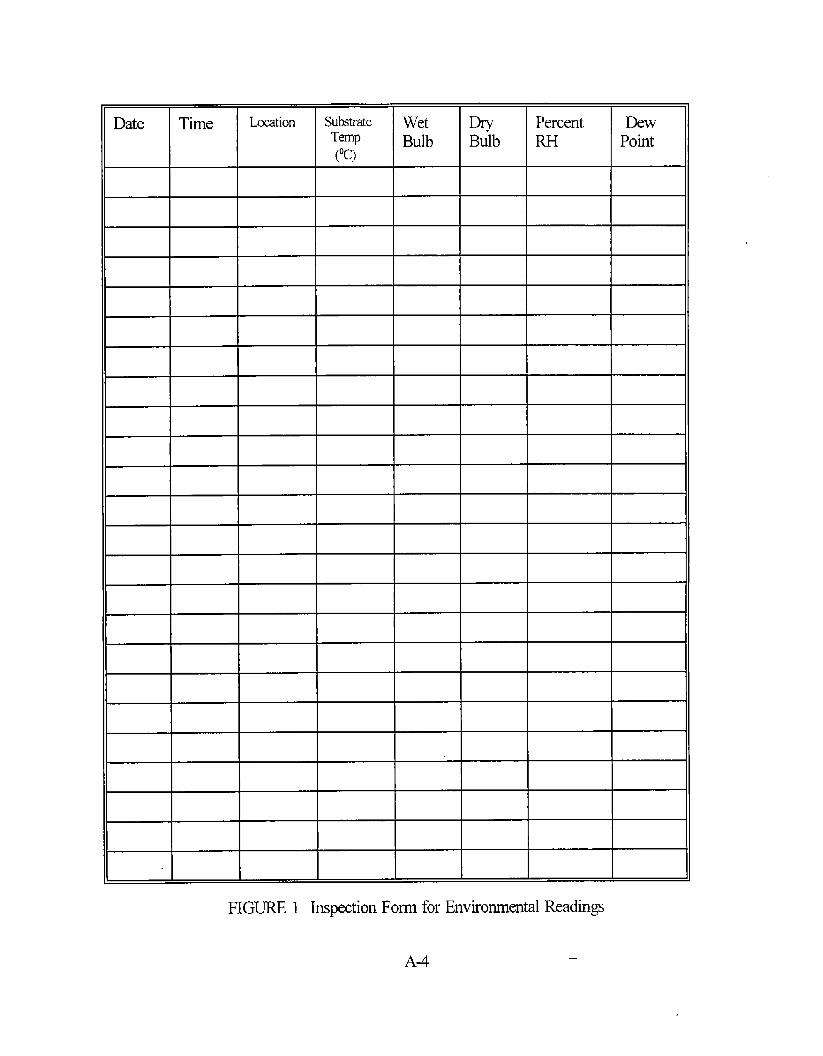
Date Time Lxation Substrate wet m’ Percent DewTemp Bulb Bulb RH Point(“c)
FIGURE 1 Inspection Form for Environmental Readings
A-4
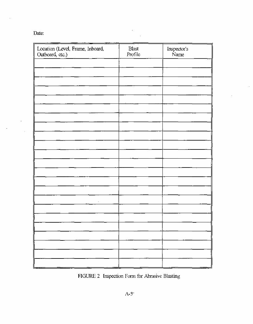
Date:
Location (Level, Frame, Inboar~ Blast Inspector’sOutboar~ etc.) Profile Name
FIGURE 2 Inspection Form for Abrasive Blasting

(THIS PAGE INTENTIONALLY LEH BLAN~

APPENDIX B
PAINTING PROCEDURE
L SCOPE
1.1 This procedure outlines the specific steps recommended for the application of thecoating system in the inter-hull space.
2. REFERENCES:
None.
IwxlREs:
1. Inspection Form for Environmental Readings2. I~pection Form for Inter-Hull Space Preservation3. Inspection Form for DW Film Thickness Measurements
3.1 It k the responsibility of the user of this work item to establish appropriate safetyand health practices and to determine the applicability of regulato~ limitations prior touse.
3.2 Install stilcient dehumidification equipment to maintain a relative humidity of 50%or less in the intw-hull space at all times.
3.2.1 Al dehumidification equipment shall be activated prior to abrasive blasting andshall remain on continuously throughout the final curing of the topcoat.
3.2.2 Environmental conditions inside the inter-hull space shall be monitored at leastevery 4 hours for temperature, dew point and relative. humidity. The initial reading shall betaken directly prior to the start of blasting. Surfaces to be painted shall be maintained at atemperature that it is 3 de~ees C (5 degrees F) or greater above the dew pod. The dewpoint shall be determined fi-omthe lowest steel surface temperature of the inter-hull space.Dehumidification equipment shall be operated to maintain relative humidity within the inter-hull space at 50% or below. The inter-hull space coatings shall be applied only whentemperatures in the inter-hull space meet the requirements of the coating manufacturer’sinstructions. Surface temperature requirements shall be as specified by the coatingmanufacturer’s instructions but shall not conflict with those stated above. Results shall beentered on Figure 1 or other method of permanent record.
.— B-1

CHECKPOINT (Swface Tempati And Dew Point)
The contractor shall complete Figure 1 and verify surface temperatures and dew pointrequirements are within the limits specified above.
3.3 Coatings used in the inter-hull space shall be a high solids, low Volatile OrganicCompound (VOC) epoxy coating system.
3,4 All personnel entering the inter-hull space shall wear coveralls, disposable booties,and clean gloves to minimize contamination of the surfaces to be painte~ as well as toprotect the primed surfaces. Entrances to the inter-hull space shall have an area to wipe solesof booties clean.
3.5 The cmtractor shall paint the inter-hull space in accordance with the requirements ofthis document and the coating manufacturer’s instructions. In the event of a conflict betweenthis document and the coating manufacturer’s instructions, the coating manufacturer and the -contractor shall mutually resolve the conflict. Figures 1 and 2 shall be used to record theinter-hull space and paint conditions prior to paint application. Appropriate steps must betaken to consider the requirements for pot life, thinning, dry times between coats (minimumand maximum), induction time, and time for fidl cure of the coating system.
3.6 Apply the fmt or prime coat of the coating system in accordance with the coatingrnanufacturds instructions and this document. Allow the fmt full coat to cure in accordancewith the coating rnanufacturets ins~ctions. A prime coat that can be indented with thefingernail shall be allowed additional time to @.
CHECKPOINT (Mner DIY Film ‘Ihickness (DF’I’))
Thickness measurements are required at five random areas per every 100 m2 (1000 N) ofpainted surface area. DFT measurements shall be recorded on Figure 3. Measurements onedges, comers and welds shall be taken for reference purposes only. There shall be NOuncoated areas.
3.7 Stripe coat all edges, weld seams, footha.nd holds, and other mounting hardware(non-flat surface) of the inter-hull space. Stripe coating shall be petiormed using therecommended method of the coating manufacturer. The stripe coat shall consist of acontrasting color to the fmt or prime coat. Stripe coating shall encompass all edges as wellas at least one-inch border outside each edge. The stripe coat thickness should be asprescribed by the coating manufacturer instructions. The stripe shall be neat in appearance,minimizing extra thicknesses applied to edges, as well as streaks and drops of paint. Paintsags and drips shall be brushed out immediately to prevent curing of excessive thicknesses.
— B-2 —

CHIKKIOINT (Stti~ Coat Application)
A visual inspection of stripe coat quality and completeness shall be performed prior to theapplication of the next stripe coat. Denote completion of this check point on Figure 2.
3.8 Apply a second stripe coat of the coating system of a contrasting color to the fu-ststripe coat, but not a light color to all edges, weld seams, fodhand holds, and other mountinghardware. Stripe coating shall be applied in accordance with section 3.7 of this procedure.
CHECKPOINT (Sttip Coat Application)
A visual inspection of stripe coat quality and completeness shall be performed prior to theapplication of the top coat. Denote completion of this check point on Figure 2.
3.9 If the top coat interval exceeds the maximum number of days from primerapplication as recommended by the coating manufacturers instructions, follow the coatingmanufactuds instructions in applying a mist or tie coat to the prime coat. A.fler a@-to-touch-time as specified by the coating manufacture~s instructions, spray apply thelight colored top coat to produce a Wet Film Thickness (WFT) in accordance with thecoating manufactures instructions and to meet the DFT requirements of the coatingmanufacturer. Random WFT measurements shall be taken during application to ensure thespecified DFT is obtained.
3.10 If a fingernail, or the base of the DFT gage can leave an impression in the coating,it is still not ready for final measurements. Perform final DFT measurements to ensure a totalsystem coverage over non-striped areas. Striped areas should naturally have a greater totalDFT.
CHECKPOINT (’FM DJ?I)
Final paint thiclmess measurements are required at five random areas per every 100 m2 (1000ff) of coated surface area. DFT measurements shall be recorded on Figure 3. There shall beNO uncoated areas.
3.10.1 Areas not having sufTlcient build of paint shall be recoated with the lightcolored top coat of the coating system until sufflci~nt final DFT is achieved. The coatingmanufactures recommended dry time prior to recoat afier application of the top coat must beobserved.
.-
3.11 Any areas that are darnaged due to weld repair, removing of staging, or other meansshall be prepared to SSPC-SP 11, power tool clean to bare metal finish, using a profileproducing mechanical tool or combination of tools such as a rotating cutter hub, flapperwheel, roto-peeq or pro-scaler type device. Circular disc sanders and needle guns ARE NOTacceptable tools for use in surface preparation in immersion areas when used alone. The
B-3
intact coating around the repaired stiace shall be “feathered’ to create a smooth transitionbetween coated and cleaned areas. Hand brush two coats of the coating system to the baremetal areas, Final system DFT in these areas shall be in accordance with the coatingmanufacturer’s recommendations.
CHECKPOINT (Holiday Check)
The contractor shall perform holiday checks on the final tank coating, using either a lowvoltage wet sponge or high voltage spark tester depending upon the expected final DFT of thecoating system. Any holiday (defects to bare metal) found will be marked by the inspector,ground out to a 1“ diameter and touched up as in Section 3.11.
3.12 Allow for proper drying time as per, the coating manufacturer’s instructions after theapplication of the final coat (including damaged touch-up areas) prior to placing the inter-hullspace back in service. Dehumidification equipment shall be used to maintain theseenvironmental conditions from abmsive blasting through final cure of the topcoat.
4. DEVIATION/WAIVJR
4.1 Any deviation to this procedure must be approved by all parties (i.e., ship owner,ship builder, coating manufacturer) and the waiver must be in writing and maintained as partof the permanent records.
B-4
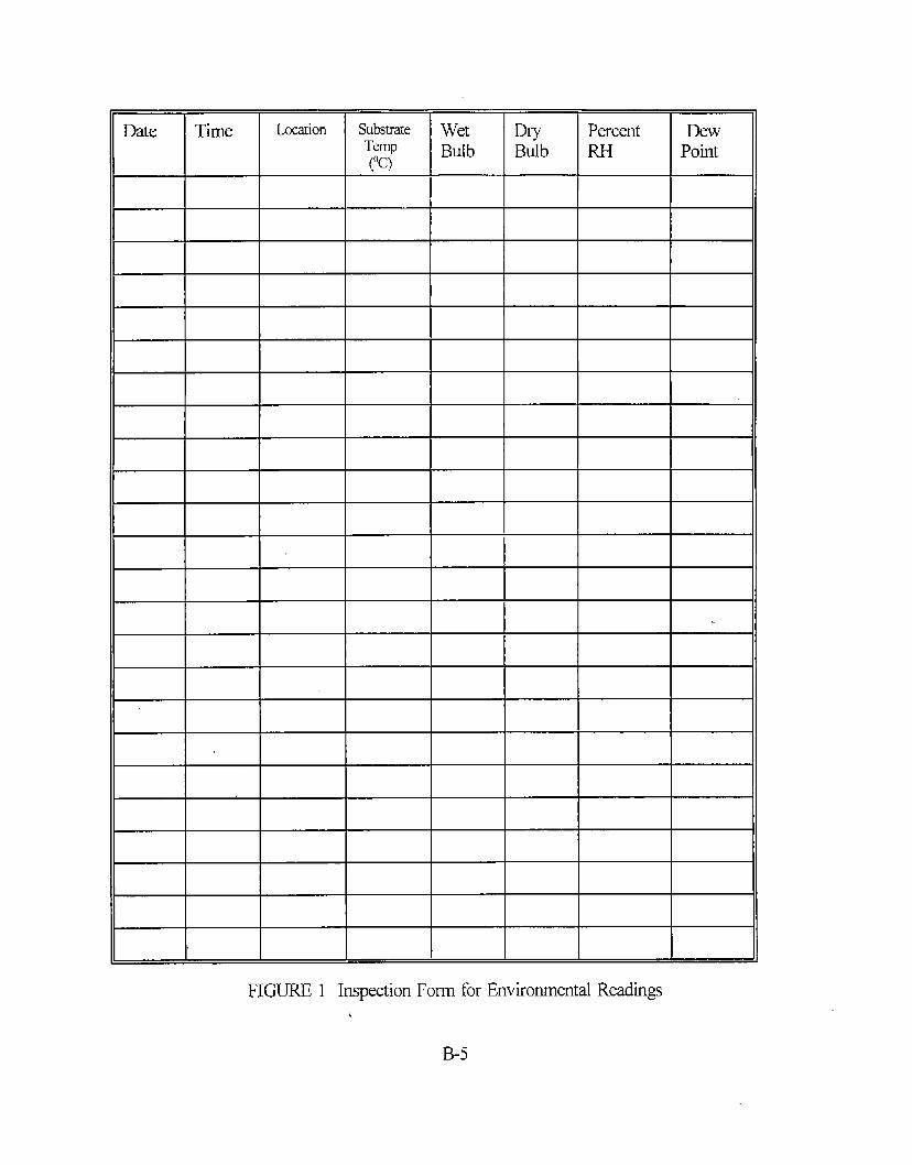
Date Time Lccation Substrate Wet m Percent DewTemp(“c)
Bulb Bulb RH Point
FIGURE 1 Inspection ForIn for Environmental Readings
B-5
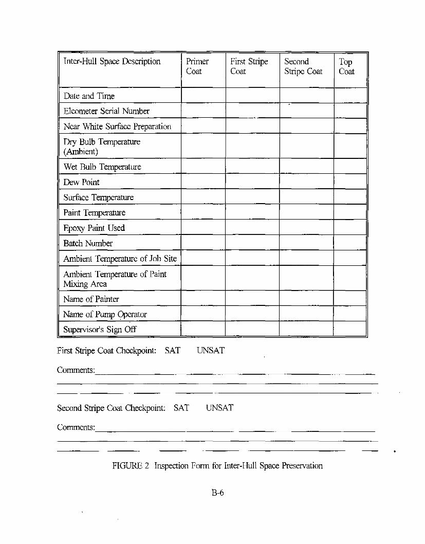
Inter-Hull Space Description Primer First Stripe Second TopCoat Coat Stripe Coat Coat
I 1 I I
Date and Time
Elcometer Serial Number
Near White Surface Preparation
Dry Bulb Temperature(Ambient)
Wet Bulb Temperature
Dew Point
Surface Temperature
Paint TempemtureI I I I
Epoxy Paint Used
Batch Number
Ambient Temperature of Job Site I
Ambient Temperature of PaintMixing Area
Name of Painter
Name of Pump Operator
Su~isofs Sign Off
First Stripe Coat Checkpoint: SAT UNSAT
comments:
Second Stipe Coat Checkpoint: SAT UNSAT
Comments:
●
FIGURE 2 Inspection Form for Inter-Hull Space Preservation
B-6
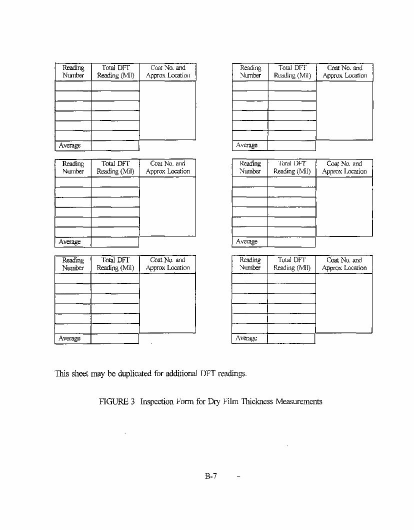
Readhg Total DFT CoatNo. andNurrbsr Readhg (M]) Approx Lmation
1
1
Average
I Reading I Total DFT I Coat No. andNumber Readhg (MII) ApproxLmation
I it
I
i II Average I I
Reachg Total DFT CoatNo. andNumkr Readhg (Mil) Approx Location
t1
1 I
Average
I Reading
I
Total D17
IcoatNo.and
Number Reading(Mil) ApproxLmation
Average
Reading Total DFT @ No. andNumkr Reading (MII) ApproxL.ccadon
I
Reading Total DIT (bat No. andNumkr Reading(Mil) ApproxMlon
Average
This sheet may be duplicated for additional DFT readings.
FIGURE 3 Inspection Form for Dry Film Thickness Measurements
B-7 -

(THIS PAGE INTENTIONALLY LEH BUNK)
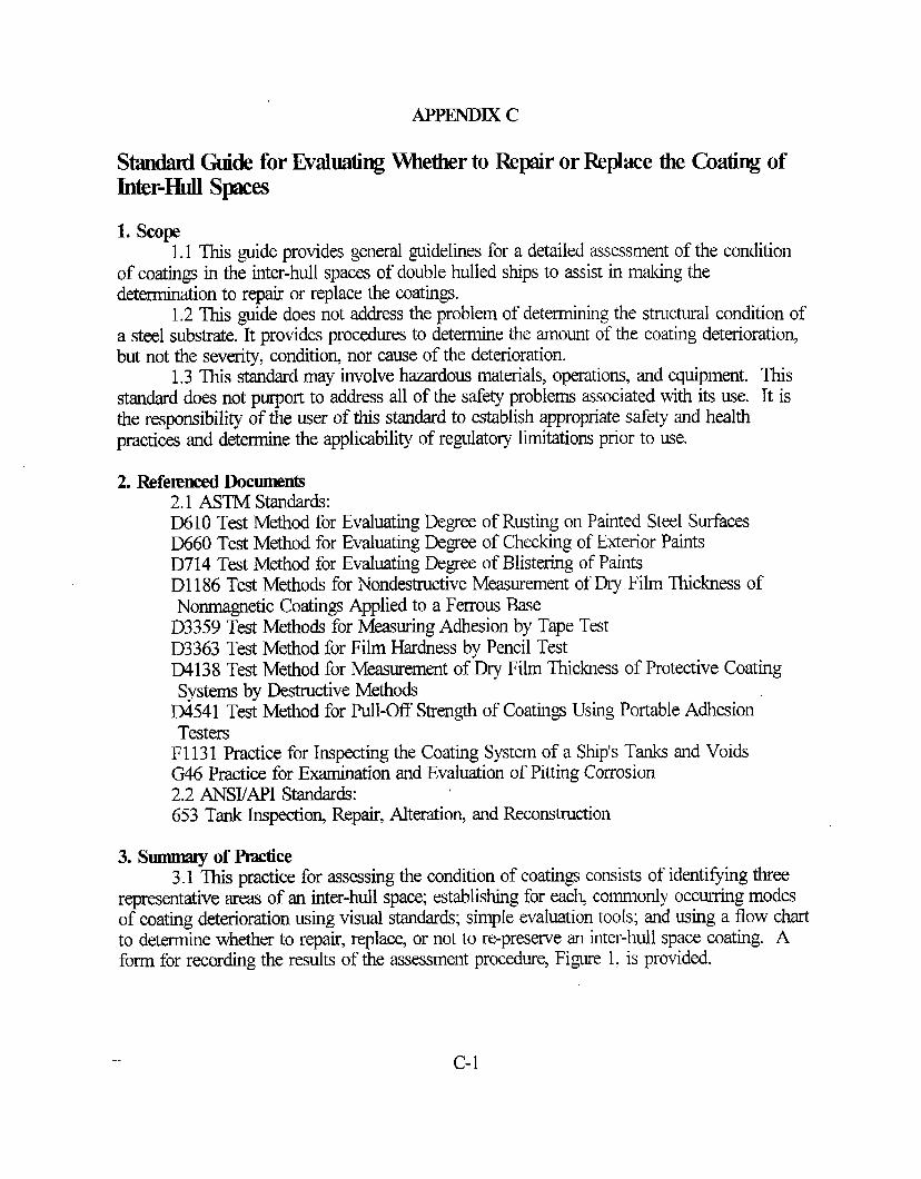
APPl@i-DIx c
StandardGuide for EvaluatingWhetherto Repairor Replace the Chating ofInter-HullSpces
1. scope1.1 This guide provides general guidelines for a detailed assessment of the condition
of coatings in the inter-hull spacm of double hulled ships to assist in making thedetermination to repti or replace the coatings.
1.2 This guide does not address the problem of determining the structural condition ofa steel substrate. It provides procedures to determine the amount of the coating deterioratio~but not the severity, conditio~ nor cause of the deterioration.
1.3 This standard may involve hanrdous materials, operations, and equipment. Thisstandard does not purport to address all of the safety problems associated with its use. It isthe responsibility of the user of this standard to establish appropriate safety and healthpractices and determine the applimbility of regulato~ limitations prior to use.
2. Referenced Docunwnts2.1 ASTM standards:D61O Test Method for Evaluating Degree of Rusting on Painted Steel SurfacesD660 Test Method for Evaluating Degree of Checking of Exterior PaintsD714 Test Method for Evaluating Degree of Blistering of PaintsD1 186 Test Methods for Nondestructive Measurement of Dry Film Thickness ofNonmagnetic Coatings Applied to a Ferrous Base
D3359 Test Methods for Measuring Adhesion by Tape TestD3363 T@ Method for Film Hardness by Pencil TestD4138 Test Method for Measurement of Dry Film Thickness of Protective CoatingSystems by Destructive Methods
D4541 Test Method for Pull-Off Strength of Coatings Using Portable AdhesionTesters
F113 1 Practice for Inspecting the Coating System of a Ship’s Tanks and VoidsG46 Practice for Exarr@ tion and Evalwtion of Pitting Corrosion2.2 ANS17API Standards:653 Tank Inspeetio~ Repair, Alteration, and Reconstruction
3. Summmy of Pmclice3.1 This practice for assessing the condition of coatings consists of identifying three
representative areas of an inter-hull space; establishing for each commonly occurring modesof coating deterioration using visual standards; simple evahation tools; and using a flow chartto determine whether to repair, replace, or not to re-presewe an inter-hull space coating. Aform for recording the results of the assessment procedure, Figure 1, is provided.
c-1
4. Preparation for Inspection4.1 This guide describes the duties of the evaluator and discusses
methods, both visual and instrumental, that can be used to determine thecoatings.
4.2 The evaluator must be able to perform the following tasks:
the evaluationcondition of the
4.2.1 Calibrate and use a magnetic gage to measure Dry Film Thickness (DFT).4.2.2 Calibrate and use eddy current thickness gages to measure DFT.4.2.3 Use a camera properly. Good illustrative photographs are of great importance as
additions to the report. A camera with auto focus, telephoto lens, datekime function andintegrated flash can be used in most types of inspections. It is important for the light sourceto reproduce CQlorscorrectly.
4.2.4 Recognize the various types of corrosion and forms of coating failure bitting,flaking, etc.).
4.2.5 Convert visual findings into accurate percent of corrosion or deterioration of thecoating system.
4.3 All saiiety requirements and the inspection plan must have been fully discussed andapproved by all parties involved (i.e., ship owner, shipyar~ coating manufacturer).
5. Impction5.1 All coatings damaged during the inspection shall be properly repaired by spot
cleaning, touching up with primer, and finishing all surfaces of disturbed areas.5.2 Vhal observation is the most important part of the evaluation process. Adequate
lighting by either hand-held flashlights or portable lighting shall be provided to the inspector.The s~ace to be inspected shall be easily accessible to the inspector. If the inspectionis completely obscured and cannot be inspecte~ denote so on the inspection form.
6. Pmcedum6.1 The following paragraphs coincide with the individual sections of Figure 1,
Inspection Fo~ Figure 1, to aid in the proper completion of Figure 1.
area
- 6.1.1 Ship d Hull Number - Indicate the name of vessel and type of vmsel and hullnumber.
6.1.2 me - Date(s) of evaluation.6.1.3 Location - City and country of shipyard location.6.1.4 Inspectofls Nme - Printed name of the evalutor.6.1.5 Irmpecto#s Signatu.m - Signature of evaluator.6.1.6 Tunk Nwnber - Indicate the ship ma evaluated by tank number. Where
appropriate, frame numbers andor ship levels shall be includd.6.1.7 Lmt l?wiow Coating System - Indicate the coating system applied by denoting
the surface preparation process employe~ year of applicatio~ and designation by name ofcoating system USQ listing the primer, all mid-coats, and topcoat.
6.1.8 PhdogrqDh - For each inspection arm a photograph of the entire area isrequired. If the area is too lmge to capture in one photograph the area should be divided intoequal sized segments and each segment should be photographed. Each photograph should bemarked with the area number, ship name, and date. Also, a size scale should be captured in
C-2

each photograph. This size scale is a reference standard that would be used to determine theapproximate size of the photographed area.
6.1.9 Inspection.4 ma - The inter-hull mea is segmented into four representative areas.The four representative areas shall be the ‘outer boundary structure’ (shell and deck), ‘innerboundary structure’ (longitudinal bulkhea~ tank top, centerline girder), ‘forward and aftboundary structure’ (bulkheads) and ‘interior non-boundary structure’ (all others).
6.1.10 Impection A wa Pementage - Determine the approximate percentage of the totalinter-hull area which represents the area being inspected. Note, for each t~ the total areafor the bulkheads, overhea~ and deck shall equal 100 percent.
6.1.11 Inspection A ma Obscuwd - If the inspection area is significantly obscured andcannot be adequately inspected, circle “YES”. If the inspection area is not significantlyobscure~ circle “NO’.
6.1.12 Conusion6.1.12.1 General Corrosion6.1.12.1.1 Overall Went of Failure - Using the overall extent diagrams enter the
number of the diagram that most closely approximates the overall extent of general corrosionper the procedures outlined in Standard Practice F1131. If there is no general corrosion inthis inspection ar~ enter the number “O”(zero) and leave the next line (extent withinaffected area) blank.
6.1.12.1.2 Extent Within Aflected Awa - Using the extent diagram within the tiected‘“” area enter the letter of the diagram that most closely approximates the extent of general
corrosion within the tiected area per the procedures outline in Standard Practice F1131. Forno corrosio~ denote by letter “A’ and move to paragraph 6.1.12.2.
6.1.12.1.3 Scaitewd or Concen~ed - Based upon the area of inspection and theoverall extent of general corrosiou determine if the corrosion is scattered or concentrated.Circle “YES” next to the appropriate determination.
6.1.12.1.4 Dgwe of Rust - Determine the percentage of the area rusted by followingthe procedure outlined in Standard Test Method D61O.
6.1.12.2 Pitting - Pitting is the localizd corrosion of a metal surface, confined to apoint or small are% that takes the form of cavities. If no pitting is present, denote in the linenext to size by entering “NONE” and move to paragraph 6.1.13.
6.1.12.2.1 Size, Shqne md Dmwity - Determine the size, shape and density of pittingby following the procedure outlined in Standard Practice G46.
6.1.12.2.2 &pth - The pit depth of the worst pit should be measured as outlined inANSI/API 653. Pit depths of 50% or more of the original metal thickness should be repaired.
6.1.13 Cotiing Bmkdown6.1.13.1 Blistering - A phenomenon peculiar to painted surfaces is the formation of
blisters at the location of some system weakness. If no blistering is noted in the inspectionar~ denote by entering “NONE” on the lines next to size and density and move to paragraph6.1.13.2.
6.1.13.1.1 Size and Density - Rate the size and density of the blister by using TestMethod D714 by entering the number that most closely approximates the largest blister andthe highest blister density in the inspection area respectively.
6.1.13.2 Mcunintiion - Delamination is characterized by detachment of the coating
C-3
fiorn the substrate or by a layer separation between the coats of paint. If no delamination isnoted in the inspection are+ denote by entering “NONE” on the line next to level and moveto paragraph 6.1.13.3.
6.1.13.2.1 Level - Determine the type of delamination observed in the inspection areaby denoting which level of delamination illustrated in Standard PracticeF1131 most closelyresembles the delamination in the inspection area.
6.1.13.3 Checking - Checking is the phenomenon manifested in coatings by slightbreaks in the coating that do not penetrate through the last applied coating. If no checking isnoted in the inspection are~ denote by entering “NONE” on the line next to degree and typeand move to paragraph 6.1.13.4.
6.1.13.3.1 ~~e und Type - Determine the degree and type of checking bycomparing the checking of the coating system with the diagrams illustrated in Test MethodD660 and select the degree and type of checking which most closely approximates thechecking noted in the inspection area.
6.1.13.4 Flaking - Determine the extent of flaking withh the affected area by usingStandard Practice F113 1 by entering the letier of the diagram that most closely approximate ‘the extent of flaking within the affected area. If no flaking is present, denote in the line nextto flaking by entering “NONE” and move to paragraph 6.1.14.
6.1.14 Mechanical Dumage - Determine the overall extent of mechanical darnage byusing Standard Practice F113 1 by entering the number of the diagram that most closelyapproximates the overall extent of corrosion due to mechanical damage. If there is nocorrosion due to mechanical damage in this inspection are< enter the number “O”(zero) andmove to paragraph 6.1.15.
6.1.14.1 Ertent Within Affected Awa - Determine the extent within the tiected areaof corrosibn due to mechanical darmige by using Standard Practice F1131 by entering theletter of the diagram that most closely approximates the extent of corrosion due to mechanicaldamage within the affected area.
6.1.14.2 Type of Damqge - If corrosion due to mechanical darnage has occurr~ usethe photographic exarnpIes of Standard Practice F 1131 to identi~ the type of mechanicaldarnage that has occurred. On the inspection fo~ circle the type of damage
.
(scrapin~impact or internal weldslburn marks) that has occurred.6.1.15 Tests6.1.15.1 Adhesion - Adhesion is the coating’s ability to remain on the substrate.
Record the test method used from either Test Methods D3359 or Test Method D4541 and theequipment used to obtain the adhesion measurements of the coatings. Enter the fivemeasurements taken for every 100 square meters within the inspection area.
6.1.15.2 @ film Thickness - Measurements of dry film thickness are of greatimportance because the protection of the substrate is directly related to the thickness of thecoating. Coating thicknesses can be determined by either Test Methods D1 186, Test Method1400, or T@ Method D4138 depending on the substrate material and whether destructive ornon-destructive tests me to be used. If destructive measurements are performed repairdarnaged areas by spot cleaning, touching up with primer, and ftishing all surfhces ofdisturbed areas. Five measurements shall be randomly taken every 100 square meters withinthe inspection area
c-4

6.1.15.3 Ham’ness - Determine the coating film hardness by performing the proceduredescribed in Test Method D3363. Five measurements shall be randomly taken every 100square meters within the inspection area.
6.1.16 Remurks - Indicate specific and overall comments which the inspector feels willassist the ship owner and operator in assessing the condition of the coating system andultimately, whether the coating system needs to be repaire~ replace~ or left as is.
6.2 The following paragraphs coincide with the individual sections of Figure 2, Figureof Merit Calculation to aid in the proper completion of Figure 2. Figure 2 shall becompleted for each of the three inspection areas of a tank.
6.2.1 Rtiing Scale - For every characteristic taken above in paragraphs 6.1.12 to6.1.15, determine a rating scale for the severity of the coating failure horn O to 10, where “O”denotes no failure’ and “10” denotes complete failure in the inspection area. As a guide, usethe overall extent of failure diagrams of Standard PracticeF1131. These diagrams depict 11different levels of failure which the inspector may use as a reference to rate the level offailure of each coating failure characteristic. The rating scale for DFT and hardness shall bedetermined based upon the findings listed in Figure 1. For low values of each the ratingscale should be greater than 5. For high values of each, the rating scale should be lower than5.
6.2.2 ill~itude Multiple - Each coating failure characteristic is provided with a pre-dettied magnitude multiple. The higher the magnitude multiple, the more significant thefailure mode is to representing coating failure. The total of all magnitude multiples is 1.0.The magnitude multiple for general corrosion is 0.2 while all other coating failurecharacteristics have a magnitude multiple of 0.1.
6.2.3 figuw of Merit (’FO~ - The figure of merit is a weighted value of a coating’sfailure characteristic. The higher the figure of merit for a particular failure characteristic, themore severe the failure is for that characteristic. Calculate the figure of merit for eachcoating failure characteristic by multiplying the number in the rating scale column (O to 10)with the number in the magnitude column (0.1 or 0.2). The value for the figure of meritshould range between 0.0 to 2.0.
6.2.4 Total Figure of Merit For Inspection A=a - The total of all coating failurecharacteristic figure of merits represents the weighted total value of all failures within theinspection area. Add the figure of merit values for each failure chmacteristic in Figure 2 toobtain this value. The higher this value, the more severe the failure is for all characteristicsof failure within the inspection area The I@hest value for the figure of merit total is 10.0.
6.2.5 Total Weighted Fig-ire of Merit For Inspection A ma - The wei@ted figure ofmerit for the inspection mea is determined by multiplying the inspection area percentage bythe figure of merit total for the inspection area. Write in this calculated value on the blankline provided in Figure 2.
6.2.6 F@w of Merit Total For Tank - The total of all weighted figure of merits forthe three inspection areas in the tank (bulkheads, overhea~ and floor) represents the weightedtotal value of all failures within the tank. Write in this calculated value in Figure 2 for allthree inspection areas of each tank. The higher this value, the more severeall characteristics of failure within the tank. The highest value for the totalmerit is 10.0.
c-5
th~ failure is fortank figure of

7. Replt7.1 Prepare an evaluation report. Figures 1 and 2 shall be completely filled in for
each tank inspected.
8. HOW Chart8.1 l?ow Cl@ - A flow chti is included as Figure 3 to assist in the decision making
for repairing, replacing, or leaving the coating system as is for each inter-hull space. Thisflow chart is based upon the current definition by the International Association ofClassification Societies (IACS) for coating conditions and other considerations.
8.2 IA CS Rtiings8.2.1 IA CS Good Condition - When there is only minor spot rusting.8.2.2 IA CS Fbir Condition - When there is local breakdown of coating at edges of
stiffeners and weld connections ardor light rusting over 20 percent or more of areas underconsideratio~ but less than as defined for poor condition.
8.’2.3IA CS Poor Condition - When there is general breakdown of coating over 20percent or more areas, or hard scale at 10 percent or more of areas under consideration.
8.3 W~er Ballast Treks -An important decision point in the flow chart is whether thewater ballast tank is a double bottom or not. This distinction is made because for ships overfive years old a “POOR” condition rated water ballast tank is required to be examinedannually if the tank is other than a double bottom tank. For double bottom water ballasttanks, where the coating is found to be in “POOR” conditio~ the tank may be examinedduring each annual survey.
8.4 Scattewd Venus Concentrtied Conmion - The repair of corrosion concentrated ina particular area of an inspection area is much easier and less costly to complete than therepair of the same amount of corrosion scattered throughout the inspection area or throughoutthe tank. Concentrated corrosion in most cases favors either repair procedures or leaving thecoating system as is, while scattered corrosion favors the replacement of the tank coatingsystem.
8.5 Cowequeme Analysis - An important parameter in the decision flow chart is therequirement to conduct a consequence analysis. This analysis considers several questionswhose answers will assist the ship owner in determining the most suitable course of action totake in preserving the inta-hull space of the vessel.
8.6 Potential Benefits for Repl~ing a Coating System - There are distinct advantag~for replacing a coating system compared to either repairing or leaving the coating system asis. The potential benefits include life extension, increased second hand value, increasedearning rate, reduced off-line for future repairs, longer period before further repair, less futurerenewal of steel work a.dor coatings, reduced insurance claims and premiums, improvedcosmetic appearance, and improved ability to conduct future surveys.
9. I’@welds9.1 assessment; corrosio~ coating inter-hull; repa~ replacement; inspection
C-6
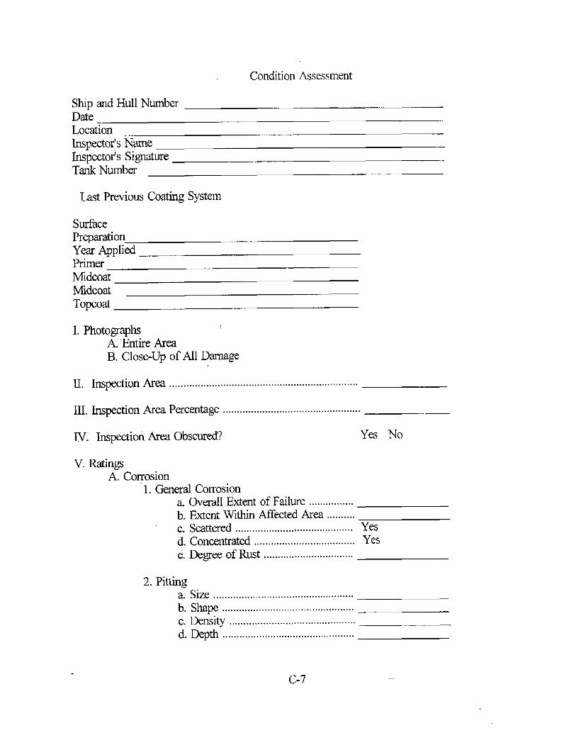
Condition Assessment
Ship and Hull NumiberDateLocationLnspector’sNameInspector’s SignatureTank Number
Last Previous Coating System
SurfacePreparationYea AppliedPrimerMidcoatMdcoatTopcoat
I. Photographs 1
A. Entire AreaB. Close-Up of All Darnage
II. Inspection Area ...................................................................
III. Inspection Area Percentage .................................................
IV. Inspection Area Obscured? Yes No
v.RatingsA. Cogosion
1. General Corrosiona. Overall Extent of Failure ................b. Extent Within Afkcted Area ..........c. Scattered ....................................------ Yesd. Concentrated .................................... Yese. Degree of Rust ................................
2. Pittinga. Size .............................-.------.....+.+.....b. Shape ...............................................c. Density ............................................-d. Depth ...............................................
c-7
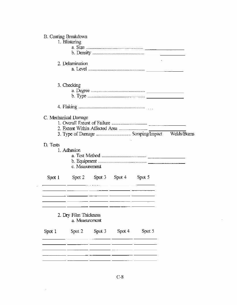
B. Coating Breakdown1. Blistering
a. Size ..................................................b. Density .............................................
2. Delaminationa. Level .................................................
3. Checkinga. Rgee ...............................................b. Type ..................................................
4. Flaking ..........................................................
C. Mechanical Damage1.2.3.
D. Tests1.
spot 1
Overall Extent of Failure ..............................Extent Within AfTected Area .........................Type of Damage .............................. Scrapinghpact welds/Bums
Adhesiona. Test Method .......................................b. Equipment ..........................................c. Measurement
spot 2 spot 3 spot 4 spot 5
2. Dry Film Thickness
spot 1
a. Measurement
spot2 spot3 spot 4 spot 5

3. Hardness
spot1
a- Measurement
spot2 spot 3 spot 4 spot 5
V. Remarks
FIGURE 1 Inspection Form
c-9
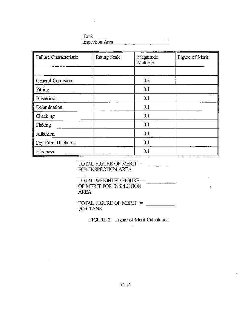
TankInspection Area
Failure Characteristic Rating Scale Magnitude Figure of MeritMultiple
General Corrosion 0.2
Pitting 0.1
Blistering 0.1
Delamination 0.1
Checking 0.1
Flaking 0.1
Adhesion 0.1
Dry Film Thickness 0.1
Hardness 0.1
TOTAL FIGURE OF MERIT =FOR INSPECTION AREA
TOTAL WEIGHTED FIGURE =OF MERIT FOR INSPECTIONAREA
TOTAL FIGUREFOR TANK
FIGURE 2
OF MERIT =
Figure of Merit Calculation
c-lo
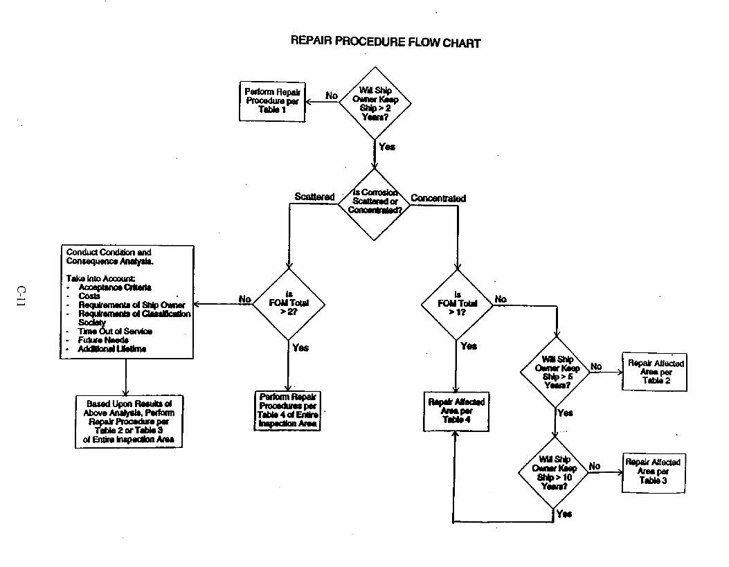
REPAIR PROCEDURE FLOW CHART
.
.
.
.
.
.
Aa=mIMmcdterhCo&
TR%!LtdsandcllFutwo MAdmmdlJothu
+
8#wluponmlsLtR8cdmvekiave-~=
Table2arT’dJiOSdEnt&e~Amn
Pabrnl Repairi%Ctp&p
4Yes
PdolmfkpakProcadmpaTddo4d -
No
W18
RwllrMlrMw#ed
Table2
IRepakMLkMwf&3d
T* 3

TABLE 1 Presemation System for Expected Lifetimeof Less Than 2 Years
- No maintenance is recommended for limited coating damage
- For instances of major coating darnage
-- Remove mu~ oil, grease
-- High pressure fresh water wash
-- Remove water
-- prepare surface to SSPC-SP 7, Brush Off Blast
-- Apply epoxy mastic (surface tolerant)
-- Two coats each at 6 roils DFT
C-12

TABLE 2 Presewation System for Expected Lifetimeof 2 to 5 Years
- Remove mu~ oil, grease
- Fresh water wash
- Remove water
- High pressure hydroblast or abrasive blast
-m
- Climate control
- Prepare surface to SSPC-SP 6, Commercial Blast Clean
- Apply epoxy mastic (surface tolerant)
- Two coats each at 6 roils DFT with an intermediate coat
C-13

TABLE 3 Preservation System for Expected Lifetimeof 5 to 10 Years
- Remove mu~ oil, grease
- Fresh water wash
- Remove water
- Dry by means of dehumidification
- Climate control
- Blast clean darnaged areas to SSPC-SP 10, Near White Metal Blast
- Coat with high build epoxy or epoxy mastic
- Two coats each at 6 rnils DFT with two intermediate stripe coats
C-14

TABLE 4 Presemation System for Expected Lifetimeof 15 to 20 Years
- Remove mu~ oil, grease
- Fresh water wash
- Remove water
. Dry by means of dehumidification
- Climate control
- Round all edges
- Smooth all welds
- Blast clean all areas to SSPC-SP
- Check for surface contamination
- Coat with high build epoxy
O,Near White Metal Blast
- Two coats each at 8 to 10 roils DFT with two intermediate stripe coats
C-15

(THIS PAGE INTENTIONALLY LEH BUNK)

APPENDIX D
StandardGuide for the Inspction of the Coating
1. SCOW
of Inter-HullSpces
-1.1 This guide describes a standard procedure for inspecting the coating system in theinter-hull spaces of double hulled ships. Included are the frequency which these inspectionsshould occur, the scope of each inspectio~ referenced documents which rate the condition ofthe coating for various characteristics, and an inspection form to record the inspection data.
1.2 This guide is intended for use only by an experienced marine coating inspector.1.3 It is intended that this guide be utilized to coordinate the inspection between the
ship owner and operators.1.4 This guide does not establish acceptireject criteria for coating inspection nor does
it address methods of repairing existing deficiencies. It does, however, provide a means ofidentifying them
1.5 This standard may involve hwardous materials, operations, and equipment. Thisstandard dm not purport to address all of the safety problems associated with its use. It isthe responsibility of the user of this standard to establish appropriate safety and healthpractices and determine the applicability of regulatory limitations prior to use.
2. Referenced Documents .-
2.1 ASTM standards:D61O Test Method for Evaluating Degree of Rusting on Painted Steel SurfacesD660 Test Method for Evaluating Degree of Checking of Exterior PaintsD714 Test Method for Evaluating Degree of Blistering of PaintsD1 186 Test Methods for Nondestructive Measurement of Dry Film Thickness ofNonmagnetic Coatings Applied to a Ferrous Base
D1400 Test Method for Nondestructive Measurement of Dry Film Thickness ofNonconductive Coatings Applied to a Nonferrous Metal Base
D3359 Test Method for Measuring Adhesion by Tape TestD3363 Test Method for Film Hardness by Pencil TestD4138 Test Method for Measurement of Ily Film Thickness of Protective CoatingSystems by Destructive Methods
D4541 Test Method for Pull-Off Strength of Coatings Using Portable AdhesionTesters
F113 1 Praetiee for Inspecting the Coating System of a Ship’s Tanks and VoidsG46 Practice for Examination and Evaluation of Pitting Corrosion2.2 ANS17API Standards:653 Tank Inspectio~ Repair, Alteration, and Reconstruction
3. Significance and Use3.1 This guide is intended as a reference for those concerned with the inspection of the
coating systems in inter-hull spaces of double hull ships. An inspection form is provided asFigure 1.
D-1 —.
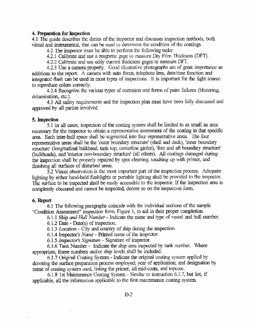
4. Pmpmation for Jmpection4.1 The guide describes the duties of the inspector and discusses inspection methods, bothvisual and instrumental, that can be used to determine the condition of the coatings.
4.2 The inspector must be able to perform the following tasks:4.2,1 Calibrate and use a magnetic gage to measure Dry Film Thickness (DFT).4.2.2 Calibrate and use eddy current thickness gages to measure DFT.4.2.3 Use a camera properly. Good illustrative photographs are of great importance as
additions to the report. A camera with auto focus, telephoto lens, datehime function andintegrated flash can be used in most types of inspections. It is important for the light sourceto reproduce colors correctly.
4.2.4 Recognize the various types of corrosion and forms of paint failures (blistering,delaminatio~, etc.).
4.3 All safety requirements and the inspection plan must have been filly discussed andapproved by all parties involved.
5. Inspection5.1 In all cases, inspection of the coating system shall be limited to as small an area
necessary for the inspector to obtain a representative assessment of the coating in that specificarea Each intro-hull space shall be segmented into four representative areas. The fourrepresentative areas shall be the ‘outer boundary structure’ (shell and deck), ‘inner boundarystructure’ (longitudinal bulkhea~ tank top, centerline girder), ‘fore and afi boundary stmcture’(bulkheads), and ‘interior non-boundary structure’ (all others). All coatings damaged duringthe inspection shall be properly repaired by spot cleaning, touching up with primer, andftishing all surfaca of disturbed areas.
5.2 Visual observation is the most important pW of the inspection process. Adequatelighting by either hand-held flashlights or portable lighting shall be provided to the inspector.The surface to be inspected shall be easily accessible to the inspector. If the inspection area iscompletely obscured and cannot be inspecte~ denote so on the inspection form.
6. Rqmrt6.1 The following paragraphs coincide with the individual sections of the sample
“Condition Assessment” inspection fo~ Figure 1, to aid in @eir proper completion.6.1.1 Ship d Hull Number - Indicate the name and type of vessel and hull number.6.1.2 Date - Date(s) of inspection.6.1.3 Locution - City and country of ship during the inspection.6.1.4 Inspector Name - Printed name of the inspector.6.1.5 Inspector’s Signatuw - Signature of inspector.6.1.6 Tank Number - Indicate the ship area inspected by tank number. Where
appropriate, fiarne numbers ancVorship levels shall be included.6.1.7 Original Coating System - Indicate the original coating system applied by
denoting the surfam preparation process employed; yea of application; and designation byname of coating system use~ listing the primer, all mid-coats, and topcoat.
6.1.8 1st Maintenance Coating System - Similar to instruction 6.1.7, but lis~ ifapplimble, all the inforrmtion applicable to the first maintenance coating system.
B-2

6.1.9 2nd Maintenance Coating System - Similm to instruction 6.1.7, but list, ifappliable, all the information applicable to the second maintenance coating system.
6.1.10 Photogr@m - For each inspection ar~ a photograph of the entire area isrequired. If the area is too large to capture in one photograph, the area should be divided intoequal sized segments and each segment should be photographed. An individual close-upphotograph of each darnaged section in the inspection area is required. Each photographshould be marked with the area number, ship name, and date. Also, a size and color scaleshould be captured in each photograph. This size scale is a reference standard that would beused to determine the approximate size of the photographed area. The color scale is areference standard for any colors which appear in the photograph.
6.1.11 Inspection A ma - The inter-hull area is segmented into four inspection areas asrefwenced above. Denote on the condition assessment form if the areas inspected ~ebulkheads, the overhea~ or the decldfloor.
6.1.12 Inspection Awa Pement~e - Determine an approximate percentage of the totalinta-hull area which represents the area being inspected. Note, for each t~ the total areafor the bulkheads, overhea~ and deck shall equal 100 percent.
6.1.13 Ih.spection A ma Obscu.wd - If the inspection area is completely obscured andcannot be inspectd circle “YES”. If the inspection area is not completely obscured circle“NO”.
6.1.14 Conmsion6.1.14.1 General Convsion - Using the overall extent diagrams enter the number of the
diagram that most closely approximates the overall extent of general corrosion per theprocedures outlined in Standard Practice F 1131. If there is no general corrosion in thisinspection ar~ enter the number “O”(zero) and leave the next line (extent within af?fectedarea) blank.
6.1.14.1.1 Extent Within Affected Area - Using the extent within tiected areadiagrams enter the letter of the diagram that most closely approximates the extent of generalcorrosion within the affected area. Remember, if the overall extent of failure line above ismarked with a “O”(zero), leave the extent within affected area line blank.
6.1.14.1.2 Scattewd or Concentrated - Based upon the area of inspection and theoverall extent of general corrosion determine if the corrosion is scattered or concentrated.Circle “YES” next to the appropriate determination.
6.1.14.1.3 Dgwe of Rust - Determine the percentage of the area rusted by followingthe procedure outlined in Standard Test Method D61O.
6.1.14.2 Pitting - Pitting is the localized corrosion of a metal surface, con.f..ed to apoint or small ar~ that takes the form of cavities.
6.1.14.2.1 Size - Determine the average size of pitting by entering the letter-numberwhich most closely approximates the sizes illustrated in Standard Practice G46.
6.1.14,2,2 Slxpe - A visual examination of the metal surface may show a roun~elongate~ or irregular opening, but it seldom provides an accurate indication of corrosionbeneath the surface. Therefore, it may be necessq to cross section the pit to see its actualshape and to determine its true depth. Determine the shape of the majority of the pits bywriting in the description of pit shapes denoted in Standard Practice G46.
6.1.14.2.3 &nsity - Determine the density of pitting by entering the lettw-number
D-3

which most closely approximates the density illustrated in Standtid Practice G46.6.1.14.2.4 Qpth - The pit depth of the worst pit should be measured as outlined in
ANSI/API 653. Pit depths of 50% or more of the original metal thickness should be repaired.6.1.15 Cotiing Bnddown6.1.15.1 Blistering - A phenomenon peculiar to painted surfaces is the formation of
blisters at the location of some system weakness.6.1.15.1.1 Overall Extent of Failuw - Determine the overall extent of blistering failure
by using Standard PracticeF1131 by entering the number of the diagram that most closelyapproximates the overall extent of blistering. If there is no blistering in this inspection are%enter the number “O”(zero) and move to paragraph 6.1.15.2.
6.1.15.1.2 Extent Within Affected A ma - Determine the extent within the affected areaof blistering failure by using Standard Practice F1131 and enter the letter of the diagram thatmost closely approximates the extent of blistering within the affected area.
6.1.15.1.3 Size - Rate the size of the blister by using Test Method D714 by enteringthe number that most closely approximates the largest blister in the inspection area.
~6.1.15.1.4 lkzsity - Rate the density of the blisters by using Test Method D714 byentering the number that most closely approximates the highest blister density in theinspection area.
6.1.15.2 &lamitiion - Delamination is characterized by detachment of the matingfi-om the substrate or by a layer separation between the coats of paint.
6.1.15.2.1 Overall Extent of Failuw - Determine the overall extent of delamination byusing Standard Practice F113 1 and enter the number of the diagram that most closelyapproximates the overall extent of delamination. If there is no delamination in this inspectionarq enter the number “O”(zero) and move to paragraph 6.1.15.3.
6.1.15,2.2 Extent Within Affected Awa - Determine the extent within the affected areaof delamination by using Standard Practice F1131 and enter the letter of the diagram thatmost closely approximates the extent of delamination within the affected area.
6.1.15.2.3 Topco~ - Mark an “X’ on the blank line beside Topcoat if topcoatdelamination has occurred.- Topcoat delamination has occurred if only the outermost coatinghas separated from all undercoats. A diagram of topcoat delamination is illustrated inStandard Practice F113 1.
6.1.15.2.4 Within Repair System - Mark an “X’ on the blank line beside WithinRepair System if delamination has occurred between layers of the repair system excludingdelamination between the topcoat and the outermost undercoat. This is topcoat delamination.The repair system is defined as any coating system that is applied on top of the originalcoating system. If the original coating system has not been overcoat~ delamination withinthe repair system is not possible. A diagram of delamination within repair system isillustrated in Standard Practice F1131.
6.1.15.2.5 Between Uri&”r&Re@- - Mark an “X’ on the blank line beside BetweenOriginal/Repair if delamination has occurred between the outermost coat of the originalcoating system and the innermost coat of the repair system. A diagram of delaminationbetween’originallrepair is illustrated in Standard PracticeF1131.
6.1.15.2.6 Within Original System - Mark an “X’ on the blank line beside WithinOriginal System if delamination has occurred between any layers of the original coating
D-4

system. A diagram of delamination within original system is illustrated in Standard PracticeF1131.
6.1.15.2.7 Top R+ner Coat - Mark an “X’ on the blank line beside Top Primer Coat ifdelamination has occurred between the innennost coat of the original coating system and theprimer coat. A diagram of delamination to primer coat is illustrated in Standard PracticeF1131.
6.1.15,2.8 To Steel Subs~e - Mark an “X’ on the blank line beside To SteelSubstrate if all coatings have separated from the surface of the hull leaving the bare steelexposed. A diagram of delamination to steel substrate is illustrated in Standard PracticeF1131.
6.1.15.2.9 Orgmic Odor Fmm D4vnitiion Area - The inspector should determine ifthere is an organic odor emanating from the delaminated area If there is an odor from anorganic solvent (such as MEK or hi-flash naphtha), circle the “YES”. If there is no organicodor, circle the “NO’.
6.1.15,2.10 Sanple Taken -If samples are taken, circle the “YES”, if not, circle the“NO’. Samples may be taken by removing some of the delaminated paint chips and placingthem into a small container. The container should be Iabelled with the area number, shipname and hull number, date, and inspector’s name.
6.1.15.3 Checking - Checking is the phenomenon manifested in coatings by slightbreaks in the coating that do not penetrate through the last applied coating.
6.1.15.3.1 Dgme - Determine the degree of checking by comparing the amount ofchecking with the diagrams illustrated in Test Method D660. If no checking is noted h theinspection ar~ denote by entering “NONE” on the line beside Degree and move to paragraph6.1.15.4.
6.1.15.3.2 Type - Determine the type of checking by comparing the checking of thecoating system with the diagrams illustrated in Test Method D660.
6.1.15.4 Flaking6.1.15.4.1 Ouerall Extent of Ftiluw - Determine the overall extent of flaking by using
Standard Practice F113 1 and enter the number of the diagram that most closely approximat~the overall extent of flaking. If there is no flaking in this inspection are% enter the number“O”(zero) and move to paragraph 6.1.16.
6.1.15.4.2 Extent Within Affected A ma - Determine the extent within the affected areaof flaking by using Standard Practice F1131 and enter the letter of the diagram that mostclosely approximates the extent of flaking within the tiected area.
6.1.16 A4echmical Dmnqge6.1.16.1 OweraZlExtent of Frnlu.w - Determine the overall extent of mechanical
damage by using Standard PracticeF1131 and enter the number of the diagram that mostclosely approximates the overall extent of corrosion due to mechanical darnage. If there is nocorrosion due to mechanical darnage in this inspection are% enter the number “O”(zero) andmove to paragraph 6.1.17.
6.1.16.2 Extent Within Affected A wa - Determine the extent within the affected areaof corrosion due to mechanical damage by using Standard Practice F1131 and enter the letterof the diagram that most closely approximates the extent of corrosion due to mechanicaldamage within the affected area.
D-5

6.1.16.3 Type of Dumuge - If corrosion due to mechanical damage has occurre~ usethe photographic examples of Standard Practice F 1131 to identi~ the type of mechanicaldamage. On the inspection fornz circle the type of damage (scrapin~impact or internalweldslburn marks) that has occurred.
6.1.17 Tests6.1.17.1 Adhesion - Adhesion is the coating’s ability to remain on the substrate.6.1.17.1.1 Test Method - Record the test method used from either Test Methods
D3359 or Test Method D4541.6.1.17.1.2 Eq@ment - Record the equipment used for the adhesion test method used
from either Test Methods D3359 or Test Method D4541.6.1.17.1.3 Meawmnent - Enter the five lmeasurements taken for every 100 squme
meters within the inspection area.6.1.17.2 Dry Film Thickness - Measurements of dry film thickness are of great
importance because the protection of the substrate is directly related to the thickness of thecoating. Coating thiclmesses can be determined by either Test Methods D1 186, Test MethodD1400, or Test Method D4138 depending on the substrate material and whether destructive ornon-d@ructive tests are to be petiormed. If destructive measurements are perform~ repairdamaged areas by spot cleaning, touching Up with primer, and ftishing all surfaces ofdisturbed areas. Five measurements shall be randomly taken eve~ 100 square meters withinthe inspection area.
6.1.17.3 Hardkess - Determine the coating film hardness by performing the proceduredescribed in Test Method D3363. Five measurements shall be randomly taken every 100square meters within the inspection area.
6.1.18 Remarks - Indicate specific and overall comments which the inspector feels will1 assist the ship omer and operator in assessing the condition of the coating system.
6.2 Responsible Personnel - Indicate all persons (name, employer, positio~ telephonenumber) whose presence is required at the time of inspection, and a procedure to follow inthe event of their absence or delay.
6.3 Timing and Frequency - Inspections shall adhere to the survey requirements of thevessel based upon the latest guidance provided by the International Association ofClassification Societies or every 30 months, whichever is more fi-equent.
6.4 Notification - Develop a procedure which establish= a specific method fornotifying all responsible parties that a ship area is ready for inspection.
6.5 Record Keeping - All elements of Figure 1 shall be filled in. Exceptions include“Maintenance Coating System” information which may not apply and the “Remarks” sectionif no comments are applicable. A procedure shall be in place to determine the dkribution ofthe inspection report.
7. Keywords7.1 assessment; coating; inter-hull; inspection; corrosion

Ship and Hull NumberDa~eLocationInspector’s NameInspector’s SignatureTank Number
Original 1st Maintenance 2nd Maintenance
Coating System Coating System Coating System
Surface Surface Surface
Preparation Preparation Preparation
Year Applied Year Applied Year Applied
Primer Primer Primer
Midcoat Midcoat MidCoat
Midcoat Midcoat Midcoat
Topcoat Topcoat Topcoat
I. PhotographsA. Entire AreaB. Close-Up of All Damage
II. Inspection Area ....................................
III. Inspection Area Percentage .................
IV. Inspection Area Obscured? Yes No
v.RatingsA. Corrosion
1. General Corrosiona. Overall Extent of Failure .............b. Extent WMin Affected Area .......c. Scattered ......................... Yesd. Concentrated ................... Yese. Degree of Rust ..............................
2. Pittinga. Size ................................b. Shape .............................c. Density ...........................d. Depth .............................
D-7
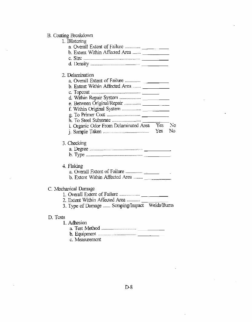
B. Coating Breakdown1. Blistering
a. Overall Extent of Failure .............b. Extent Within Affected Area .......c. Size ...............................................d. Density .........................................
2. Delaminationa, Overall Extent of Failure .............b. Extent Within Affected Area .......c. Topcoat .........................................d, Within Repair System ..................e. Between Original/’Repair ..............f. Within Original System ................g. To Primer Coat ............................h. To Steel Substrate ........................i. Organic Odor From Delaminated Area Yes No
j. Sample Taken ...................................... Y= No
3. Checkinga. Degree ............................................b. Type ...............................................
4. Flakinga. Overall Extent of Failure ..............b. Extent Within MTected Area ........
C. Mechanical Darnage1. Overall Extent of Failure .................2, Extent Within Affected Area ...........3. Type of Daqmge ...... Scrapii@mpact Welds/Bums
D. Tests1. Adhesion
a. Test Method .............................b. Equipment ................................c. Measurement
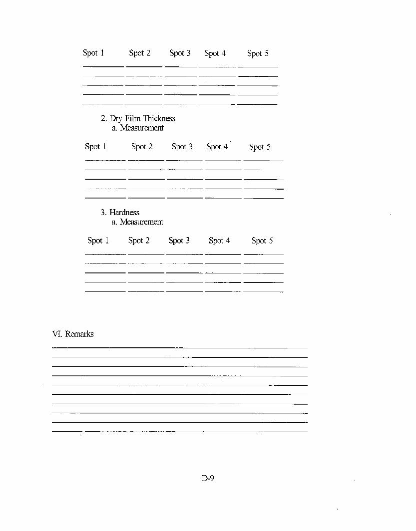
spot 1 spot2 spot 3 spot 4 spot5
2. Dry Film Thicknessa. Measurement
spot 1 spot2 spot 3
3. Hardnessa Measurement
spot 1 spot 2 spot 3
spot4 “ spot5
spot4 spot5
VI. Remarks
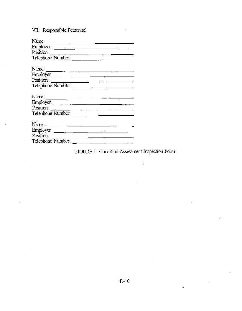
VII. Responsible Personnel
NameEmployerPositionTelephone Number
NameEmployerPositionTelephone Number
NameEmployerPositionTelephone Number
NameEmployerPositionTelephone Number
FIGURE 1 Condition Assessment Inspection Form
APPENDIX E
StandardGuide for the Quality Assumnce Requiimmts for Application ofCbatings tl) Steel Sudaces of Inter-HullAreas
1. Stop1.1 This guide provides a standard guide for the quality assurance requirements for the
application of coatings to steel surfaces of inter-hull areas of double hull ship designs.1.2 It is intended for this guide to be utilized to verify the proper application of the
coating system during either new build or repair/replacement of the existing coating system.1.3 Variations or simplifications of the practice set forth herein may be appropriate for
special coating work such as maintenance or qualifications of equipment suppliers shoppersonnel. It is not the intent of this practice to mandate a singular basis for all qualityassurance.
1.4 This standard may involve hazardo~ materials, operations, and equipment. Thisstandard does not purport to address all of the safety problem associated with its use. It isthe responsibility of the user of this standard to establish appropriate safety and healthpractices and determine the applicability of regulato~ limitations prior to use.
2. Referenced Documents2.1 ASTM standards:D1 186 Test Methods for Nondestructive Measurement of DFT of NonmagneticCoatings Applied to a Ferrous Base
D1400 Test Method for Nondestructive Measurement of Dry Film Thickness ofNonconductive Coatings Applied to a Nonferrous Metal Base
D1411 Test Methods for Water-Soluble Chlorides Present as Admixes in GradedAggregate Road Mixes
D2200 Pictorial Surface Preparation Standards for Painting Steel StructureD3276 Standard Guide for Painting Inspecton (Metal Substrates)D4417 Test Methods for Field Measurements of Surface Profile of Blast Cleaned SteelD4940 Test Method for Conductimetric Analysis of Water Soluble IonicContamination of Blasting Abrasives
D5 162 Practice for Discontinuity (Holiday) Testing of Nonconductive ProtectiveCoating on Metallic Substrates
F718 Shipbuilders and Marine Paints and Coatings ProductiProcedure Data Sheet2.2 Steel Structure Painting Council Standards:SSPC-SP 10 Near-White Blast CleaningSSPC-AB 1 Mneral and Slag Abrasives2.3 Federal RegisterVolume 55 Paragraph 11798 Toxicity Characteristic Leaching Procedure
3. Definitions3.1 lkscription of Terms Specfic to This Stdmd
E-1 —
3.1.1 CertZjic~ion - Written documentation of qualification.3.1.2 Quality Assurmce - A form of quality control which provides the necessary
cmlidence that a particular task has been completed to predetermined standards ofworkmahip.
3.1.3 @Zity Asswmce Inspector - An individual who has worked in the coating tradeand is sufficiently trained and certified to properly examine, observe. and measureconformance of the coating work to predetermined quality requirements.
3.1.4 Prnnting Supervisor - An individual who has worked in the painting trade longenough to have sticient experience and knowledge in the practical application of coatings topro~-rly supervise other painters.
4. Sunumuy of Pmctice4.1 This practice establishes the quality assurance requirements for the coating
amlication in the inter-hull areas of double hull ship designs and is intended to increase the~tildence for the proper application of the coating-system for an expected service life of 15to 20 years.
4.2 This standard will identi~ who will perform the inspection, when the inspectionsshall be conducte& how frequently the inspections shall be conducte~ quality assurance formfor recording the results of each quality assurance check poin~ and methodology forcorrection-of a quality assurance attribute which fails a check point.
5. Petiomance5.1 The shipbuilder shall maintain a certification program for the quality assurance
(QA) inspector. The QA inspector must be proficient in deterrninin g the acceptability ofsurface preparation prior to commencement of coating application, deterrninin g the degree ofcompliance with blasting and painting procedures appropriate to the surface preparation andcoating materials being use~ and determining the acceptability of finished products inaccordance with established standardized acceptance criteria. The coating inspector’s training,as a rninimurq shall be certified by the Council of Engineering and Scientific Specialty Board(CESB).
5.2 The QA inspector shall be properly outfitted to petiorm the inspections describedherein. In addition to the equipment listed in this guide, the inspector shall have a pencil andnote pad to make appropriate notes. The QA forms should k filled in with a pencil duringthe inspection and photocopies of the filled in forms should be signed in ink. The signedcopy of the inspection form shall be maintained as part of the permanent QA record.
5.3 The QA inspector is responsible for the inspection of material receipt and storage,environmental cmditions, rounding of edges, abrasive blast profile, substrate chlorideconcentration stripe coat completeness, city film thickness readings, holiday check anddamage and spot repair work completeness.
5.4 The inspection of material receipt and storage facilities shall be done periodically(i.e., prior to seawater ballast tank work in each new build ship or major repair of sea waterballast tanks in an in-service ship) to ensure paints are being stored and receipt inspected inaccordance with ASTM F718 and that the abrasive blast media conforms to quantitativerequirements. All requirements of the coating manufacturers Material Safety Data Sheets
— E-2

(MSDS) shall be adhered to by the shipbuilder.5.4.1 The abrasive blast media shall conform to limits for crystalline silicq chloride
content, conductivity, toxicity, and hardness. These limits shall be verified at least for eve~batch or barge load of abrasive blast media or whenever the blast media is provided by adifferent supplier.
5.4.1.1 The manufactur~ of the abrasive blast media shall certify that the maximumcrystalline silica content of the abrasive is less that 1.0 percent by weight. Crystalline silicashall not be intentionally added to the abrasive media.
5.4.1.2 The chloride content of the abrasive shall be less than 0.03 percent by weight.Test for clioride content shall be in accordance with ASTM D14 11.
5.4.1.3 The conductivity of the abrasive shall be less than 290 m.icrosiemens persquare centimeter. Test for conductivity shall be in accordance with ASTM D4940.
5.4.1.4 The manufacturer shall certify that the toxicity characteristic content of theabrasive media shall not exceed the values listed in Federal Register (FR), Volume 55,paragraph 11798, March 19, 1990 (55 FR 11798), Toxicity Characteristic Leaching Procedure(TCLP).
5.4.1.5 The abrasive material shall have a minimum hardness of 6 on the Mobs scale.5.5 The QA inspector is required to examine all environmental data maintained by the
painting supawisor. The environmental conditions shall be monitored at least eve~ 4 hoursfor temperature, dew point, and relative humidity and recorded on a form similar to Figure 1.The initial reading shall be taken directly prior to the start of abrasive blasting. Theenvironmental conditions within the inter-hull space to be prmerved shall cotiorm to therequirements of the coating manufacturers MSDS sheets. Qu@ions relating to the coatingmanufacture~s MSDS sheets shall be brought to the attention of the coating rnanufacture~srepresentative and resolved between “representatives of the coating manufacturer, shipbuilder,and ship owner prior to coating application.
5.5.1 Thennometem-The painting supemisor may need several types of thermometersand should have at least an accurate pocket thermometer with a range from about Oto 1500F(-18 to 65°C) for measuring the ambient air temperature. The same thermometer or a floatingdairy thermometer may be used to determine the temperature of liquid coating, solvent, etc.The pocket thermometer may also be used for determining the temperature of metal surfa~by placing it against the metal while shielding the outer (away from the metal) side of thebulb by means of putty or similar material, so that the reading is not affected by the ambienttemperature. Flat surface-temperature thermometers are also available for this purpose.
5.5.2 M Point-A psychrometer containing a wet and dry-bulb thermometer fordeterminingg relative humidity and dew point is recommended. Hand-held sling or electrimltypes are available as well w direct reading digital types.
5.6 It has been observed that when paint is applied to a sharp edge, the paint willdraw away born the sharp edge leaving the edge with relatively poor paint coveragecompared to the remaining flat surfaces. There is strong evidence that suggests radiusing orrounding sharp edges will promote improved coating perfommnce.
5.6.1 The rounding of edges by the shipbuilder shall be verified by the QA inspector.Edge radius= shall be a minimum of 3 mm and shall be measured at least every 100 linearfeet (30 linear meters) with a prefabricated template. No more than 10 percent of the total
E-3
number of measurements shall be below 3 n-urnand no measurement shall be less than 2.7mm. Satisfacto~ completion of rounding shall be denoted by the QA inspector on Figure 2.
5.7 Abrasive blast cleaning is used to remove foreign materials from the substrate andto provide a roughened surface by striking the substrate with a stream of small, hard abrasiveparticles such as dry mineral, grit, slag, and shot.
5.7.1 Mineral and slag abrasives shall meet the requirements of SSPC-AB 1.5.7.2 The QA inspector shall veri~ each inter-hull space has been properly abrasive
blasted to near white metal in accordance with SSPC-SP 10 or equivalent by signature onFigure 3. Surface preparation is one of the most important factors affecting the performanceof the coating system. Wherever possible, the vacuum blast method is recommended. Thereshould be no dust on the surface during this part of the inspection.
5.7.1 Pictorial Stan&d ASTM D2200 (SSPC-Vis 1) should be provided to theinspector. The standard is used by the inspector to determine whether the degree of surfacepreparation specified (SSPC-SP 10) has been attained throughout the aRected space.
5.7.2 The average surface profile shall be 2.0 to 4.0 nils based upon a minimum offive measurements per 100 square meters or as required by the contract. Profilemeasurements shall be performed per ASTMD4417 Method C, Replica Tape Method.Individual QA data shall be recorded on Figure 3 or equivalent, signed by the QA inspector,and retained as part of the permanent QA record.
5.8 Surface contamination with chlorides has been shown to lead to rapid blistering ofan organic coating in immersion conditions. The basic mechanism is likely due to osmoticpressure developed under the coating when it acts as a semi-permeable membrane.
5.8.1 The QA inspector shall perform surface chloride contamination checks on freshlyblasted surfaces, using the cotton ball swab method of collection followed by titration or theBresle blister patch method. Measurements shall be made randomly over blasted surface atdifferent locations in the inter-hull space. One measurement per 100 square meters shall bemade. If any direct measurement exceeds 3 p~cm2 of chloride, a high pressure water wash ofthe surface is required. Satisfactory substrate chloride concentrations of 3 pglcm2 or lowershall be noted by the QA inspector by signature on Figure 4.
5.9 Dry fdm’thickness (DFT) measurements are of great importance because theprotection of the substrate is directly related to the thickness of the coating. There are twoways of making the measurements: nondestructive y or destructively. The latter involvespenetrating or cutting through the film to the substrate with a needle or blade and measuringthe distance between the top and bottom of the film. This method is not recommended forinter-hull spaces. For inter-hull spaces, nondestructive film thickness measurements usingTest Methods D1 186 or Test Method D1400 are recommended.
5.9.1 Coating thickness measurements shall be performed at a minimum of fiverandom areas for every 100 square meters of painted surface area for every coat of paint.DFT measurements shall be recorded on Figure 5 and shall conform to the DFT requirementsof the coating manufacturer’s product information sheets. Areas not having sufficient buildduring the final DFT readings shall be recoated until sufficient final DFT is achieved. Thereshall be no uncoated areas during all paint coats.
5.10 As previously mention~ there is a tendency for the coating to pull away fromthe edge. This rmults in a much thinner coating and one that offers a much reduced barrier
E4

coating for the substrate. Since edge failure is the leading cause of tank coating failure,additional steps are required to resolve this problem. Stripe coating, in combination withradiusing, enhances the performance of the coating system on susceptible areas such as edges.
5.10.1 The QA inspector shall perform a visual inspection for satisfactory applicationof the stripe coats. The stripe coats shall be of contrasting colors to one another and to theinitial prime coat. The stripe coat shall encompass all edges, as well as a 2.5 cm borderoutside each edge. The stripe coat thickness should be nominally 4 to 5 nils DFT and shallbe neat in appearance, with minimal streaks and drops of paint. DFT measurements shall benoted on Figure 5. Paint sags and drips shall be brushed out immediately to prevent thecuring of excessive thicknesses.
5.11 The QA inspector shall conduct a holiday check of the coating system applied perASTM D5 162 Practice for Discontinuity Testing of Nonconductive Protective Coating onMetallic Substrates. Results of the holiday checks shall be noted on Figure 5. All holidaysshall be marked and appropriately repaired as “per the coating manufacturers productinformation sheet or coating manufacturers representative directions.
5.11.1 The QA inspector shall use an inspection mirror for viewing under beams,under pipes, behind stiffeners, and other hard to spray areas for areas with no or insufficientcoating coverage.
5.12 All areas darnaged by weld repair, removal of staging. or other means shall beprepared to a b~e metal SSPC-SP 11 finish using a profile producing mechanical tool orcombination of tools. All damaged areas shall be noted on Figure 5. The intact coatingaround the repaired surface shal~be “feathered” to create a smooth transition between coatedand cleaned areas. Hand brush two coats of the coating system to the bare metal areas. Finalsystem DFT readings in these areas shall conform to the requirements of the coatingmanufacturers product information sheets.
6. ~Oi’dS6.1 A personnel qualification records file shall be established for each QA inspector
and be maintained by the shipbuilder.6.2 Collection, storage, and control of records required by this guide shall be in
amordance with the requirements of the shipbuilder and ship owner.
7. [email protected] quality assurance inspecto~ coatings inspection; corrosion; environmental
conditions; substmte chloride; dry film thickness; holiday check stripe coats
E-5
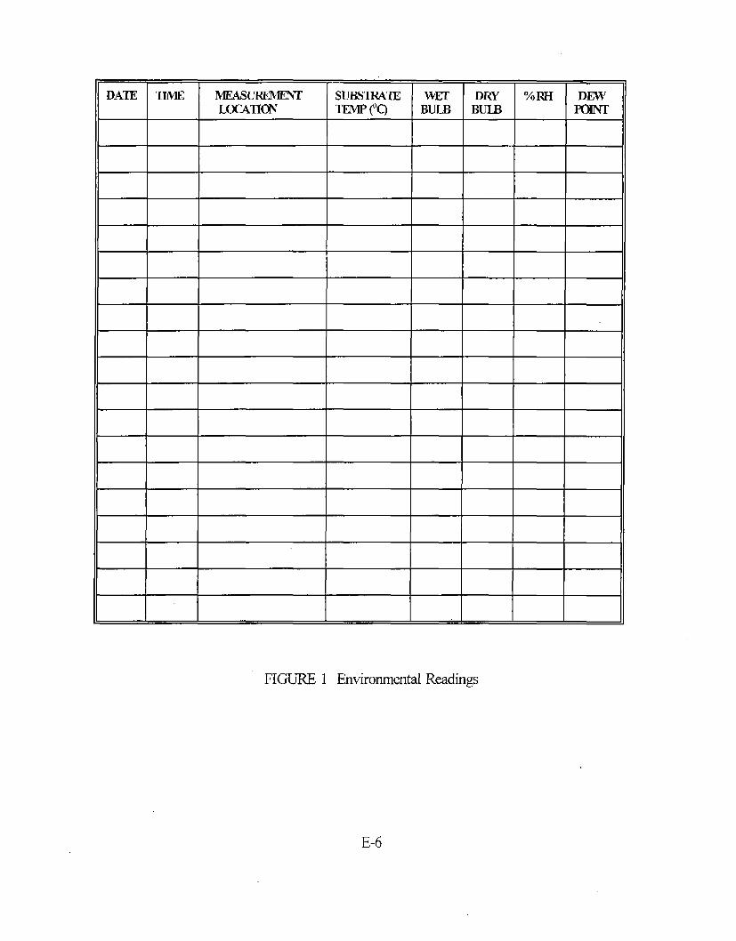
DATE m MEAsmHvllmm Sulsrlwm wEl- DRY %RHmmm TEMP(’Q BULB BULB ;K
FIGURE 1 Environmental Readings
E-6

LcrATIm @mmJNBoARD, SAllSFA~Y 1311W lNsHrl-011’sOU’IEC)ARD,m m) RCKJND~G SIGNAIUl?E
FIGURE 2 Rounding of Edges
E-7

DATEABRASIVE MATERLW
IAx4mm (FR’4m INBOARD, cuMNLmms To BL4ST rNsPIXITR’sOuTBos, m m) SSK-SP 10 SI~A~
FIGURE 3 Abrasive Blasting
E-8

DATE
LmAmm - JNBOARD, CHLORIDE INwFCmR’s0UTm4RD, LEVEL E-rc) RE4DING SIGNA’IURE
FIGURE 4 Chloride Readings
E-9

1. DRY FILM THICKNESS @lW): MEASUREMENTS
COATNO.& LOCATION SPOT1 SPOT2 SPOT~ SPOT4 SPOT5 AVER4GE
2. EIIXJDAY C’HIWIL
DATE:
LOCATION(w INBOARD, SATISFA~ORY INSPECTOR’SOUTBOARD,LEVEL,ETC.) (YESOR NO*) SIGNATURE
*: CORRECTIVE ACTION REQUIRED IF HOLIDAY CHECK IS UNSATISFACTORY
E-10 “
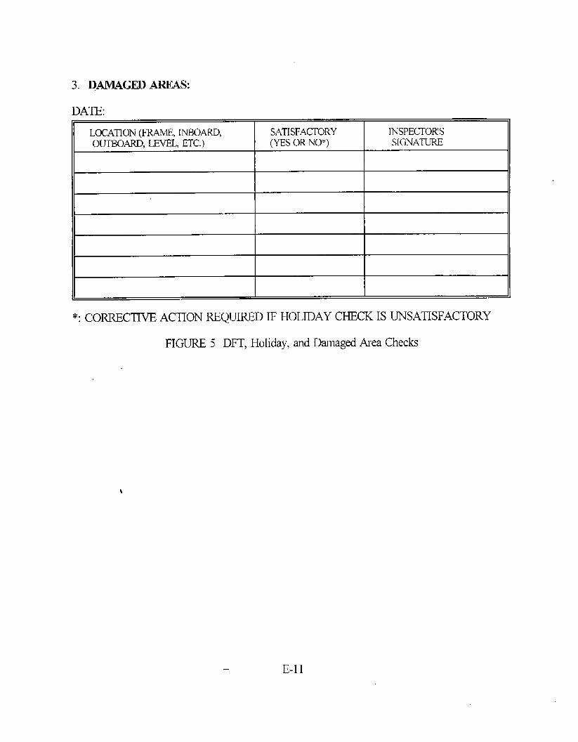
3. DAMAGED AREAS:
DATE:
LOCATION- INBOARD, SATISFACTORY INSPECTOR’SOUTBOARD,LEVEL,ETC.) (YESOR NO*) SIGNATURE
I I
*: Corrective ACTION REQUIRED IF HOLIDAY CHECK IS UNSATISFACTORY
FIGURE 5 DFT, Holiday, and Damaged-ha Check
\
E-n
(THIS PAGE INTENTIONALLY LE17 BUNK)

APPENDIX F
StandardGuide for the Tmining of JbumeymanPainte~, PaintingSupvisom,and Paint I@ctm for Double Hull Ships
1. sco~1.1 This guide provides a training plan to assist in the qualification of journeyman
painte~, painting supervisor, and paint inspecto~ to apply, supervise, and inspect theapplication of specified coatings to inter-hull designed ships.
1.2 Variations or simplifimtions of this guide may be appropriate for special coatingwork outside the emphasis of the int~-hull spaces of ships. It is not the intent of this guideto mandate a singular basis for all training plans and subsequent qualification.
1.3 This standard may involve hazardous materials, operations, and equipment; Thisstandard does not purport to address all of the safety problem associated with its use. It isthe r~po~ibility of the user of this standard to establish appropriate safety ~d h~th .
practices and determine the applicability of regulato~ limitations prior to use.
2. Referenced Documnti2.1 ASTM standards:D1 186 T@ Methods for Nondestructive Measurement of Dry Film Thickness ofNonmagnetic Coatings Applied to a Ferrous Base
D4138 Test Method for Measurement of Dry Film Thickness of Protective CoatingSystems by D@ructive Methods
D4228 Practice for Qualification of Journeyman Painten for Application of Coatingsto Steel Stiaces of Safety-Related Areas in Nuclear Facilities
D4286 Practice for Determining Coating Contractor Qualifications for NuclearPowered Electric Generation Facilities
D4414 Practice for Measurement of WFT by Notch GagesD4537 Guide for Establishing Procedures to Qualify and Certify Inspection Personnelfor Coating Work in Nuclear Faciliti~
D5 162 Practice for Discontinuity (Holiday) Testing of Nonconductive ProtectiveCoating on Metallic Substrates
3. Definitions3.1 Jowneyman Painter -An individual who has stilcient experience in the painting
trade to master the use of all applicable tools and the materials being applied.3.2 Pa”nting Supewisor - An individual who has worked in the painting trade long
enough to have stilcient experience and knowledge in the practical application of coatings toproperly supervise other painters.
3.3 Paint Inspector - The designated representative of the owner or of the coatingsmanufacturer, or both who has sticient experience and knowledge in the practiuilapplication and evaluation of coatings applied to steel surfaces.
3.4 Governing ficuments - Technical specifications, job site procedures, and reference
F-1
materials,
4. Significance and Use4.1 The requirements of this guide apply to personnel who perform the tasks of(1)
pa~ting, (2) painting supewisor, (3) paint inspector.4.2 It is the responsibility of each organization participating in the project to ensure
that only those personnel within their respective organizations who meet the requirements ofthis guide are permitted to perform the duties and activities covered by this guide.
4.3 The organization(s) responsible for establishing the applicable requirements foractivities covered by this guide shall be identified, and the scope of their responsibility shallbe documented. Delegation of this responsibility to other qualified organizations is permittedand shall be documented.
4.4 It is the responsibility of the organization pertonning these activities to specify thedetailed methods and procedures for meeting the requirements of this guide, unless they areotherwise specified in the contract document.
5. Requirements for Jbumeyman Painter5.1 This guide requires the journeyman painter to know the required stiety rules and
regulations which govern proper gas freeing of spaces, emergency egress tiom the paintingOpwation, and other specific safety requirements of the job site. The painter shall be properly
outfitted with all required personnel protective equipment.5.2 The journeyman painter shall be familiar with the various standards of surface
preparation.5.3 The journeyman painter shall be familiar with the coating materials mixing
requirements and shall demonstrate proper mixing procedures.5.4 The journeyman painter shall be familiw with paint application techniques
associated with brush, roller, conventional spray, airless spray, and plural componentequipments.
5.5 The journeyman painter shall demonstrate his/’her ability to take wet film thicknessreadings using Test Method D4414 during the coating application demonstration.
5.6 The journeyman painter shall demonstrate his/her ability to apply the specifiedcoating in a uniform Dry Film Thickness (DFT) in accordance with the governing documents,as evaluated by the paint inspector. All paint application techniques expected to be utilized ininter-hull spaca shall be demonstrated.
6. Requirerrmts of h Painting S~misor6.1 The painting supervisor shall be trained to understand the requirements for gas
freeing spaces to be painted and his/’her responsibilities for ensuring these spaces are properlygas freed. For example, the painting supervisor shall ensure adequate li@ng and ventilationis provided in the tank and that a proper gas free certificate has been issued and posted in aconspicuous location by the gas free engineer.
6.2 The painting supervisor shall be trained to understand hiw’herresponsibilities toensure the journeyman painten assigned to hirrdher have been provided w-ithand are properlywearing all personnel protective equipment.
F-2

6.3 The painting supervisor shall be trained to and be familiar with the proper and safeerection of staging in the tank to properly prepare and paint all interior surfaces of the tank.
6.4 The painting supervisor shall be trained to understand the importance ofmaintaining the proper environmental conditions in inter-hull spaces to support thepreservation of these spaces and shall ensure the requirements of these conditions are inaccordance wifi the governing documents.
6.5 The painting supewisor shall be trained to identi~ the equipment necess~ totake temperature readings of the space, the steel surface, dew point, and relative humidity,and to ensure these readings are taken in accordance with the governing documents. Thepainting supervisor shall be knowledgeable in the corrective procedures to take in the eventenvironmental conditions within the inter-hull area are not within the prescribed requirementsof the governing documents.
6.6 The painting supemisor shall be trained and be farnilim with various surfacecleaning methods such as abrasive blasting, Vacuum blast, hydroblast, hand tool cleaning, andpower tool cleaning for inter-hull spaces m well as the disadvantages and advantagm of eachcleaning method.
6.7 The painting supervisor shall be familiar with the surface preparation requirementsof the inter-hull spaces and ensure the painters under his~er supervision have complied withthe re.uuirements of the governing documents. To do so, the painting supervisor shall befamilih with and have a~cess to}ictorial examples of the s~ace cleanliness standardsrequired by the governing documents.
6.8 The painting supervisor shall ensure the coating materials are properly mixedaccordance with the govening documents.
6.9 The painting supervisor shall be trained to properly use all the necessaryequipment for the proper application of the specified coating. Their knowledge must be
in
sufficient to provide the necessag guidance and recommendations to the painters under theirsupervision to ensure the requirements of the governing documents are met.
6.10 The painting supemisor shall be trained to ensure WFT and DFT readings of thepainted surfaces are taken to verifj that the proper paint thicknesses have been applied by thepainters in accordance with the governing documents. All areas which do not comply with therequirements of the governing documents shall be repaired to meet these requirements.
6.11 The painttig supervisor shall be ~Owl~@able On the Coating repair.requirements set forth in the governing documents and to provide the necess~ guidance tohis/her painters to comply properly with these requirements in repairing the deficient areas.
7. Requirements of the Paint Inspctor7.1 The paint inspector shall be capable of implementing and recording all inspections
required by the governing documents and governing bodies (ship owner, classification socie~,authorities, shipyar~ sub-contractors, labor org~intions, etc.).
7.2 The paint inspector shall possess knowledge and experience in the following arm.different typm of vessel and structural elements; function and method of operation of inter-hull spaces; preparation and use of specifications; inspection planning; safety and safetyprocedures; rigging of scaffolding and accessibility; steel work surface preparation methodsand equipment; properties of different coating systems; selection and application of coatings;
F-3
climate control and ventilation: cathodic protection; quality control and testirg use of andcalibration of measurement equipment; characterization and assessment of different types ofcorrosion; identification and assessment of different types of coating damage; use of differenttypes of inspection equipment; familiar with all aspects of the inspection requirements of thegoverning documents.
8. EmlliI’MtiO~
8.1. The journeyman painter shall apply the specified coating in conformance to thegoverning documents to a test panel similar in detail to the inter-hull space. An example of atest setup is provided in Standard Practice D4228.
8.2 The painting supervisor shall be given an examination covering the general,specific, and practical aspects of coatings application to inter-hull spaces. The examinationshould be both written and practical.
8.3 The paint inspector shall be given an examination covering the general,specific, and practical aspects of coatings inspection. The examination can be either writte~in the form of a personal interview, or a combination of both.
9. Evaluation9.1 Evaluation of the journeyman painter shall be made by the painting supervisor
and the paint inspector. Both individuals shall be thoroughly familiar with the specifiedcoating material(s) and acceptance criteria and shall be aware of any difficulties in applyingthe coating on surfaces similar to that found in inter-hull spaces.
9.1.1 The painting supervisor and the paint inspector shall take dry film thickness ,readings on all mm of the sample test area by either Test Methods D1 186 or Test MethodD4138. These readings shall be used to verify the specified dry film thickness requirementshave been met and the uniformity of the coating application.
9.1.2 The painting supemisor and the paint inspector shall inspect the finished surfaceto verifi that it conforms to the requirements of the governing documents and PracticeD5162.
9.2 Evaluation of the painting supervisor shall be made by a paint inspector and aproduction-related qualifying agent. Both individuals shall be thoroughly familiar with thespecified coating material(s), all associated safety requirements, acceptance criteria for thecoating material(s), and shall be aware of any difficulties in applying the coating on anysurface,
9.2.1 The paint inspector and quali~ing agent shall verify the painting supervisor isproficient in the requirements listed in section 6.
9.3 Evaluation of the paint inspector shall be made by two quali~ing agents. Onlyone qualifying agent can be production-related.
9.3.1 The qualifying agents shall be thoroughly familiar with all aspects of thespecified coating material(s), the acceptance criteria for the coating lmaterial(s), the inspectionrequirements of the coating material(s), and all difficulties in applying the coating to the tmtpanel.
F-4

10*Rep-t10.1 The report of the j~urneyman paintefs petiormance shall be sirrk to Figure 1.10.1.1 Me - Date(s) ot the test.10.1.2 Jowmeyma - Printed name of the journeyman painter.10.1.3 Pa”nting Supervisor - Printed name of the painting supewisor.10.1,4 Prnnt Inspector - Printed name of the paint inspector.10.1.5 Test Pmzel Locution - The numbered location on the test panel where@ Film
Thickness (DF~ measurements are taken.10.1.6 DFT Reding - The DFT measurements taken at each test panel location.10.1.7 /description of Finish Su~ae - Written description by the painting supewisor
and paint inspector on the qualitative appearance of the coating system on the test panel.10.1.8 it4atetiaZ - Record the type of coating system used in the test application.10.1.9 DFT Range - Record the range of acceptable DFT measurements for the coating
system used in the test application.10.1.10 Holi@ Detection - Record the type of holiday detection equipment used on
the test panel.10.1.11 Signatuw ofJoum~m~ Painter - Signature of journeyman painter.10.1.12 Sigmlum of Painting Supemisor - Signature of painting supewisor.10.1.13 Si@w of Paint Izzspector - Signatie of paint inspector.10.1.14 The report shall become a permanent part of the journeyman paintefs
personnel record.10.1.15 A copy of the report shall be given to the qualifying journeyman painter.10.2 The report of the painting supemisor’s performance shall be similar to Figure 2.10.2.1 Me - Date(s) of the examination.10.2.2 Ptinting Supervisor - Printed name of the painting supervisor.10.2.3 Pa-nt Inspector - Printed name of the paint inspector.10.2.4 Qudfiing Agent - Printed name of the qualifying agent.10.2.5 Eccrnination Scows10.2.5; 1 General Portion - Record the score of the painting supervisor’s perfomce in
the general portion of the examination.10.2.5.2 Specific Portion - Record the score of the painting supervisor’s performance
in the specific portion of the examination.10.2.5.3 Pmtical Portion - Record the score of the painting supewisor’s performance
in the practical portion of the examination.10.2.6 Comments - Written remarks by the paint inspector and/or qualifying agent
concerning the performance of the painting supervisor in the examination.10.2.7 Recommended By10.2.7.1 Si- of Painting Supervisor - Signature of the painting supemisor.10.2.7.1.1 Title - Title of the painting supervisor.10.2.7.2 Sigmture of Paint Inspector - Signature of the paint inspector.10.2.7.2.1 Title - Title of the paint inspector.10.2.7.3 Signatu~ of the Qua@ing Agent - Signature of the qualifying agent.10.2.7.3.1 Title - Title of the qualifying agent.10.2.8 The report shall become a permanent part of the painting supervisor’s personnel
F-5

record.10.2.9 A copy of the report shall be given to the quali~ing painting supewisor.10.3 The report of the paint inspector’s performance shall be similar to Figure 3.10.3.1 Date - Date(s) of the examination.10.3.2 Paint Inspector - Printed name of the paint inspector.10.3.3 Qudfving Agent - Printed name of one of the qualifying agent.10.3.4 QuulZfiing Agent - Printed name of the other quali~ing agent.10.3.5 Examination Scows10.3.5.1 Genaul Portion - Record the score of the painting supervisor’s performance in
the general portion of the examination.10.3.5.2 Specific Portion - Record the score of the painting supervisor’s performance
in the specific portion of the examination.10.3.5.3 F!mtical Potiion - Record the score of the painting supervisor’s performance
in the practical portion of the examination.10.3.6 Comments - Written remarks by the paint inspector ancVorqualifying agent
concerning the performance of the painting supervisor in the examination.10.3.7 Recommetied By10.3.7.1 Signatm of Qudfiing Agent - Signature of the qualifying agent.10.3.7.1.1 Title - Title of the qualifying agent.10.3.7.2 Sign@m of Quall~ing Agent - Signature of the other qualifying agent.10.3.7.2.1 Title - Title of the other quali~ing agent.10.3.8 The report shall become a permanent part of the painting supemisor’s personnel
record.10.3.9 A copy of the report shall be given to the qualifying paint inspector.
11. Certification11.1 All qualifications are certified for a period not to exceed three years. All
personnel are required to be recertified whenever a new coating system is stipulated to beused in the governing documents.
12. Records12.1 As noted in section 10, personnel qualification records shall be established and
maintained by the employer. The collection, storage, and control of records required by thisguide shall be in accordance with the requirements of the responsible organintion andappropriate governing documents.
13. I’@[email protected] journeyman painteq painting superviso~ paint inspector; training coatings
inspection
F-6

Test Application of Coating to Standmd Panel Testby Journeyman Painter for Qualification
Date:Journeyman:Painting SupervisionPaint Inspector:
Test Panel Location
#1#2#3#4#5#6#7#8#9#lo
Description of
DFT Reading
Finished Surface:
Material:DFT Range:Holiday Detection:
Signature
Signature
Signature
of Journeyman Painte~
of Painting Supervisor:
of Paint Inspector
FIGURE 1 Record Form for Test Application for Journeyman Painter
F-7

Record of Examination of the Painting Supervisor
Date:Painting Supervisor:Paint Inspector:Qualifying Agent:
Examination Scores:
General PortionSpecific PortionPractical Portion
Comments:
Recommended
SignatureTitle:
SignatureTitle:
SignatureTitle:
of Painting Supervisor:
of Paint Inspecto~
of Qualifying Agent:
FIGURE 2 Sample Record of Examination for the Painting Supervisor
F-8 --

Record of Examination of the Paint Inspector
Date:Paint hspecto~QualifyingQualifying
Agent:Agent:
Examination Scores:
General PortionSpecific PortionPractical Portion
Cornrnents:
Recommended by:
Signature of- ‘“” “ ‘ “Title:
QuaIllylng Agent:
Signature of Qualifying Agent:Title:
FIGURE 3 Sample Record of Examination for the Paint Inspector
F-9
Project Technical Committee Members
The following persons Were members of the committee that represented the Ship StructureCommittee to the Contractor as resident subject matter experts. As such they performedtechnical review of the initial proposals to select the contractor, advised the contractor incognizant matters pertaining to the contract of which the agencies were aware, and performedtechnical review of the work in progress and edited the final report.
Rickard Anderson –Chairman
James Baker
John Burkhart
Jadeep Sirkar
Alan Bentz
Chao Lin
Harvey Hack
John S. John
Kcn KarisAllen
Marty Hecker
Prof. John McIntyre
David Witmer
Mr. William Siekierka
Dr. Robert Sielski
CDll Steve Sharpe
Military Sealift Command
Military Sealift Command
Military Sealift Command
U.S. Coast Guard
U.S. Coast Guard
Maritime Administration
Naval Surface Warfare Center
American Bureau of Shipping
Defence Research Establishment Atlantic
U.S. Coast Guard
Advanced Polymer Services
BP Oil Marine
Naval Sea Systems Command,Contracting Officer’sTechnical Representative
National Academy of Science,Marine Board Liaison
U.S. Coast Guard, Executive DirectorShip Structure Committee
COMMllTEE ON MARINE STRUCTURES
Commission on Engineering and Technical Systems
National Academy of Sciences - National Research Council
The COMMIITEE ON MARINE STRUCTURES has technical cognizance over the
interagency Ship Structure Committee’s research program.
John Landes, University of Tennessee, Knoxville, TN
Howard M. Bunch, University of Michigan, Ann Arbor, Ml
Bruce G. Collipp, Marine Engineering Consultant, Houston, TX
Dale G. Karr, University of Michigan, Ann Arbor, Ml
Andrew Kendrick, NKF Services, Montreal, Quebec
John Niedzwecki, Texas A & M University, College Station, TX
Barbara A. Shaw, Chairman, Pennsylvania State University, University Park, PA
Robert Sielski, National Research Council, Washington, DC
Stephen E. Sharpe, Ship Structure Committee, Washington, DC
DESIGN WORK GROUP
John Niedzwecki, Chairman, Texas A&M University, College Station, TX
Bilal Ayyub, University of Ma@and, College Park, MD
Ovide J. Davis, Pascagoula, MS
Maria Celia Ximenes, Chevron Shipping Co., San Francisco, CA
MATERIALS WORK GROUP
Barbara A. Shaw, Chairman, Pennsylvania State University, University Park, PA
David P. Edmonds, Edison Welding Institute, Columbus, OH
John F. McIntyre, Advanced Polymer Sciences, Avon, OH
Harold S. Reemsnyder, Bethlehem Steel Corp., Bethlehem, PA
Bruce R. Somers, Lehigh University, Bethlehem, PA

RECENT SHIP STRUCTURE COMMITTEE PUBLICATIONS
SSC-389
SSC-388
SSC-387
SSC-386
SSC-385
“SSC-384
SSC-383
SSC-382
SSC-381
SSC-380
SSC-379
SSC-378
SSC-377
SSC-376
SSC-375
SSC-374
SSC-373
Ship Structure Committee Publications - A Special Bibliography Thisbibliography of SSC reports may be downloaded from the internet at:http: //www.starsoftware. com/uscg nmc/nmc/sscl /index.htm
Inspection of Marine Structures L. Demsetz, R. Cario, R. Schulte-Strathaus, B. Bea 1996
Ship Structural Intearity Information Svstem-Phase II M. Dry, R.Schulte-Strathaus, B. Bea 1996
Guideline for Evaluation of Finite Elements and Results R. 1. Basu, K. J.Kirkhope, J. Srinivasan 1996
Ship’s Maintenance Proiect R. Bea, E. Cramer, R. Schulte-Strauthaus, R.Mayoss, K. Gallion, K. Ma, R. Holzman, L. Demsetz 1995 ,
Hydrodynamic Impact on Displacement Ship Hulls -An Assessment ofthe State of the Art J. Daidola, V. Mishkevich 1995
Post-Yield Strenqth of Icebreakirm Ship Structural Members C.DesRochers, J. Crocker, R. Kumar, D. Brennan, B. Dick, S. Lantos 1995
Optimum Weld-Metal Strenqth for Hiqh Strermth Steel Structures R.Dexter and M. Ferrell 1995
Reexamination of Desicm Criteria for Stiffened Plate Panels by D. Ghoseand N. Nappi 1995
Residual Strenqth of Damaqed Marine Structures by C. Wiernicki, D.Ghose, N. Nappi 1995
Ship Structural Inteqritv Information System by R. Schulte-Strathaus,B. Bea 1995
Improved Ship Hull Structural Details Relative to Fatiqueby K. Stambaugh, F. Lawrence and S. Dimitriakis 1994
The Role of Human Error in Desian, Construction and Reliability ofMarine Structures by R. Bea 1994,
Hull Structural Concepts For Imnroved Producibility by J. Daidola,J. Parente, and W. Robinson 1994
Ice Load Impact Studv on the NSF RN Nathanial B. Palmer by J. St.John and P. Minnick 1995
Uncertainty in Strenqth Models for Marine Structures by O. Hughes,E. Nikolaidis, B. Ayyub, G. White, P. Hess 1994
Effect of Hiqh Strenath Steels on Strenqth Considerations of Desiqn andConstruction Details of ShiPs by R. Iieyburn and D. Riker 1994
Loads and Load Combinations by A. Mansour and A. Thayamballi 1994