Corrosion and abrasion of steel walls in the cargo space ... · 3 Introduction – Trailing suction...
17
Corrosion and abrasion of steel walls in the cargo space of trailing suction hopper dredgers 13/11/2013
Transcript of Corrosion and abrasion of steel walls in the cargo space ... · 3 Introduction – Trailing suction...

Corrosion and abrasion of steel
walls in the cargo space of
trailing suction hopper dredgers
13/11/2013

2
Introduction
The steel plating of the cargo hold of a trailing suction hopper dredgers
suffers from excessive wear.
The presentation will describe :
• Trailing suction hopper dredger and the concerned area
• Problem definition – Wear of cargo hold plating
• Causes and damage mechanism
• Methods to mitigate or resolve the wear problem
• Conclusion

3
Introduction – Trailing suction hopper dredger
Trailing hopper suction dredger:
• Trailing a drag head over the seabed
• Removal of top layer seabed and sucking material into the vessel’s cargo/hopper hold
• Discharging dredged material by bottom doors, floating line or rainbow nozzle

4
Introduction – Trailing suction hopper dredger
Cross section of a TSHD cargo hold
Top view on TSHD cargo hold

5
Problem definition – Wear of cargo hold plating
The vessel’s integrity fails due to wear of structural members:
• Locally f.e. wear of plating which cause holes and possible leakages.
wear of welds which initiates cracks in welds & plating
• Globally f.e. wear of plates and primary stiffening causing buckling of
plate fields.
Wear of structural steel members is mainly caused by corrosion and in
particular cases by abrasion or galvanic corrosion.
6
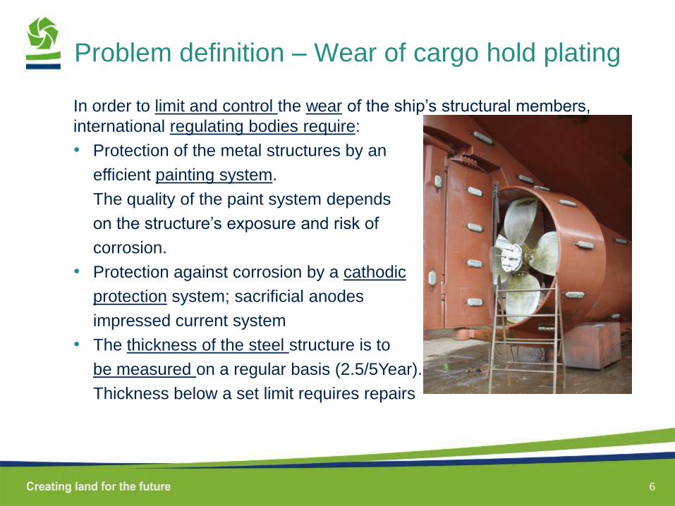
Problem definition – Wear of cargo hold plating
In order to limit and control the wear of the ship’s structural members,
international regulating bodies require:
• Protection of the metal structures by an
efficient painting system.
The quality of the paint system depends
on the structure’s exposure and risk of
corrosion.
• Protection against corrosion by a cathodic
protection system; sacrificial anodes
impressed current system
• The thickness of the steel structure is to
be measured on a regular basis (2.5/5Year).
Thickness below a set limit requires repairs
7
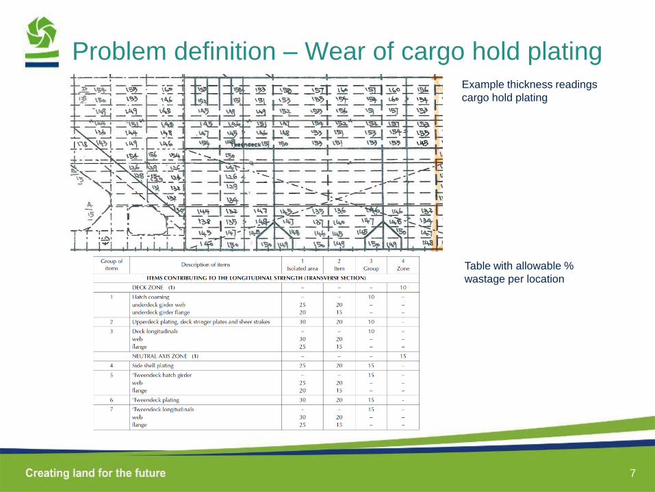
Problem definition – Wear of cargo hold plating Example thickness readings
cargo hold plating
Table with allowable %
wastage per location
8
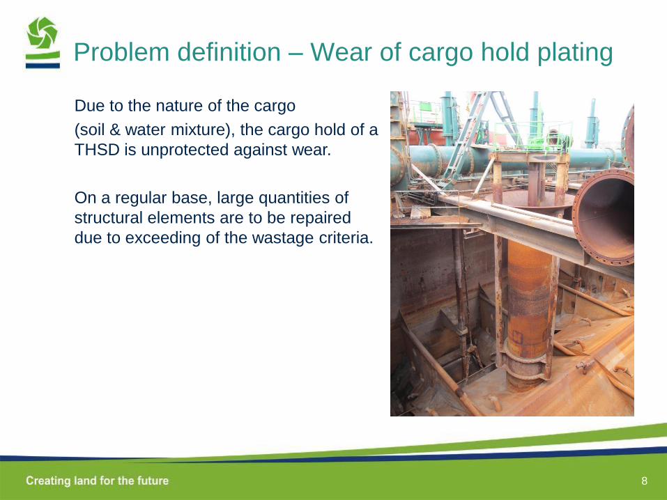
Problem definition – Wear of cargo hold plating
Due to the nature of the cargo
(soil & water mixture), the cargo hold of a
THSD is unprotected against wear.
On a regular base, large quantities of
structural elements are to be repaired
due to exceeding of the wastage criteria.

9
Causes and damage mechanisms
Causes of wear: Corrosion vs Abrasion.
Strong indicators that base mechanism is corrosion:
• The water-wind strake wears approximately twice as
much as the lower sections, which are permanently
submerged.
• Plate thickness reduction goes faster in tropics.
Temperature strongly influenced corrosion, but has no
influence on the abrasion.
• No difference in thickness reduction is noticed in
areas where there’s a lot of turbulence and
consequentially abrasion; near loading points or plate
strake at overflow level.
Abrasion of sand cargo is not the base mechanism for
wear, but certainly accelerates the corrosion by
removing the oxide layer on top the structural elements.
After 10 Year service:
P17.5mm -> wear 2.2mm
P15 mm -> wear 1.2mm
10
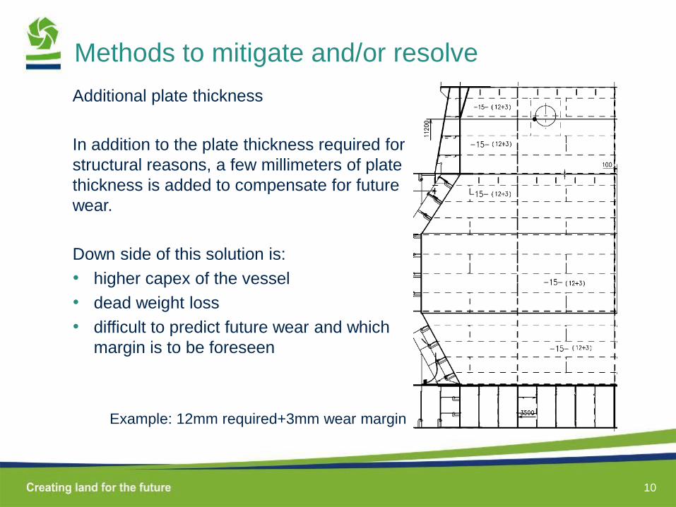
Methods to mitigate and/or resolve
Additional plate thickness
In addition to the plate thickness required for
structural reasons, a few millimeters of plate
thickness is added to compensate for future
wear.
Down side of this solution is:
• higher capex of the vessel
• dead weight loss
• difficult to predict future wear and which
margin is to be foreseen
Example: 12mm required+3mm wear margin
11
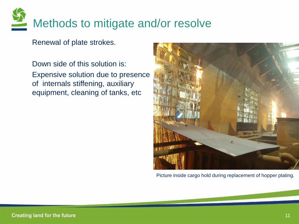
Methods to mitigate and/or resolve
Renewal of plate strokes.
Down side of this solution is:
Expensive solution due to presence
of internals stiffening, auxiliary
equipment, cleaning of tanks, etc
Picture inside cargo hold during replacement of hopper plating.
12
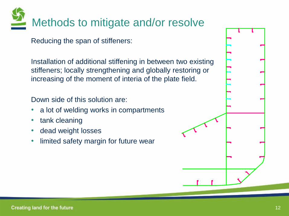
Methods to mitigate and/or resolve
Reducing the span of stiffeners:
Installation of additional stiffening in between two existing
stiffeners; locally strengthening and globally restoring or
increasing of the moment of interia of the plate field.
Down side of this solution are:
• a lot of welding works in compartments
• tank cleaning
• dead weight losses
• limited safety margin for future wear

13
Methods to mitigate and/or resolve
Wear plates:
Wearing plates welded on the existing worn structural plates.
Down side of this solution:
• Plates should not participate in the longitudinal strength of the ship
• Dead weigh loss (approx. half of the thickness can be worn).
• Issues with corrosion in between structural and wearing plating.

14
Methods to mitigate and/or resolve
Wear resistant coatings.
Down side of these solutions are:
• These coatings require strong anchor profile for good adhesion; SA2 ½
grit blasting in covered newbuilding hall very cumbersome.
• Large impact on production progress
• Once slightly damaged by impact or cutting, the paining peel’s off easily.
15
Methods to mitigate and/or resolve
Cathodic protection against corrosion by sacrificial anodes or ICCP
systems.
Down side of these solutions are:
• Sacrificial anodes have limited effect once covered with sticky soil
• ICCP systems are too fragile for use in a cargo hold and have a
limited life time.
16
Methods to mitigate and/or resolve
FEM calculations
The Bureau Veritas class notation “Veristar Hull” prescribes repairs of
plate wear, not based on general rules, but based on FEM calculation for
a particular area on particular vessel.
If the tensions in plate field with reduced thickness do not exceed the
limit, no repairs are to be executed.
Down side of this solution:
• A lot of engineering hours are required to build up and to maintain the
calculation model.
17
Conclusion
In order to avoid extensive repairs of cargo hold plating, a combination of
previously described methods seems to be best answer.
The combination is determined by type of vessel and considered area in
the cargo hold.
Or are there new solutions? …suggested by material experts?