Correlation Between Vortex Ring Formation and...
9
Biomedical Engineering Correlation Between Vortex Ring Formation and Mitral Annulus Dynamics During Ventricular Rapid Filling ARASH KHERADVAR,*† MICHELE MILANO,† AND MORTEZA GHARIB*† One of the most important fluid phenomena observed in the left ventricle during diastole is the presence of vortex rings that develop with a strong jet entering through the mitral valve. The present study is focused on the rapid filling phase of diastole, during which the left ventricle expands and re- ceives blood through the fully open mitral valve. The atrio- ventricular system during the rapid filling phase was emu- lated experimentally with a simplified mechanical model in which the relevant pressure decay and the dimension of mitral annulus approximate the physiologic and pathologic values. Digital particle image velocimetry measurements were correlated with the force measurements on the mitral annulus plane to analyze the relation between flow and the mitral annulus motion. The recoil force on the displaced annulus plane was computed on the basis of plane accelera- tion and plane velocity and correlated with the inflow jet. Measurements of the recoil force for different values of the mitral annulus diameter showed that the recoil force was generated during fluid propulsion and that it is maximal for an annulus diameter close to the normal adult value in a healthy left ventricle. We also tested annulus diameters smaller and larger than the normal one. The smaller annulus corresponds to the stenotic valves and the larger annulus exists in dilated cardiomyopathy cases. In both conditions, the recoil force was found to be smaller than in the normal case. These observations are consistent with the previously reported results for dilated cardiomyopathy and mitral steno- sis clinical conditions. ASAIO Journal 2007; 53:8-16. T he topic of vortex rings has received much attention over the past few years. Vortex rings occur in nature wherever propulsive flow exists, from erupting volcanoes to the ones generated by squid and jellyfish to propel them. They are also present in the left ventricle (LV). The current understanding of the formation process and dynamics of the vortex rings has been extensively described in the literature. 1–4 However, the process of vortex ring formation and its influence on dynamics of the left heart have not been elucidated so far. The presence of vortex rings that develop during cardiac diastole was initially recognized by in vitro visualization of the ventricular flow 5,6 and subsequently confirmed by analyses based on color Doppler mapping 7,8 and magnetic resonance imaging. 9,10 During diastole, when the left ventricle is filling with the blood jet from the atrium, the ventricle expands, and as a result, the atrioventricular plane moves in the opposite direction with respect to blood flow. Little has been done so far to understand if any correlation exists between this movement and the formation process of the vortex ring created by the blood jet. Vortex rings typically develop from a jet or slug of fluid ejected from a nozzle. In fluid mechanics, mitral inflow is considered a starting jet ejected from left atrium to the left ventricle. The characteristic stroke ratio of a starting jet (L/D), typically produced by a piston-cylinder mechanism, is identified as the ratio of the ejected jet length L T u piston (t)dt; where u piston is the piston ve- locity, t is time, and T is the period of piston displacement) to the effective jet diameter (D). This ratio is usually referred to as “formation time” 3,11,12 and is a nondimensional measure of time. Gharib et al. 3 discovered that by increasing the stroke ratio of a starting jet to values 4, in semi-infinite space, no additional energy or circulation enters the leading vortex ring and the re- maining fluid in the pulse will be ejected as a trailing jet. After this stage, the vortex ring is said to have pinched off from the starting jet, and as a result, the size of the leading vortex ring cannot increase. The value of the stroke ratio (formation time) at which pinch-off occurs is recognized as vortex formation number. Gharib et al. 3 experimentally showed that regardless of the jet velocity and the nozzle size, in a semi-infinite space, the forma- tion number lies between 3.6 and 4.5. In a different experimental study, Krueger and Gharib 13 showed that the time-averaged thrust generated by a pulsed jet in semi-infinite space would be maximized once a vortex ring with maximum circulation is created. In other words, once the stroke ratio of a pulsed jet is large enough to pinch off the leading vortex ring and initiate formation of the trailing jet flow, further increase in stroke ratio does not increase the time-averaged thrust. Krueger and Gharib 13 emphasized that formation of a single leading vortex ring has a more significant role in efficient generation of thrust when compared with the trailing jet. In the present article, we studied the formation of a vortex ring in a confined chamber in contrast to previous studies done in a semi-infinite space. The objective was to understand the dynamics of mitral annulus plane and its correlation with From the *Cardiovascular and Biofluid Dynamics Laboratory, Cali- fornia Institute of Technology, Pasadena, California; and the †Gradu- ate Aeronautical Laboratory, California Institute of Technology, Pasa- dena, California. Submitted for consideration May 2006; accepted for publication in revised form July 2006. Reprint requests: Dr. Arash Kheradvar, Mail Code 301– 46, Califor- nia Institute of Technology, 1200 East California Boulevard, Pasadena, CA 91125. DOI: 10.1097/01.mat.0000249870.44625.22 ASAIO Journal 2007 8
Transcript of Correlation Between Vortex Ring Formation and...

Biomedical Engineering
Correlation Between Vortex Ring Formation and MitralAnnulus Dynamics During Ventricular Rapid Filling
ARASH KHERADVAR,*† MICHELE MILANO,† AND MORTEZA GHARIB*†
One of the most important fluid phenomena observed in theleft ventricle during diastole is the presence of vortex ringsthat develop with a strong jet entering through the mitralvalve. The present study is focused on the rapid filling phaseof diastole, during which the left ventricle expands and re-ceives blood through the fully open mitral valve. The atrio-ventricular system during the rapid filling phase was emu-lated experimentally with a simplified mechanical model inwhich the relevant pressure decay and the dimension ofmitral annulus approximate the physiologic and pathologicvalues. Digital particle image velocimetry measurementswere correlated with the force measurements on the mitralannulus plane to analyze the relation between flow and themitral annulus motion. The recoil force on the displacedannulus plane was computed on the basis of plane accelera-tion and plane velocity and correlated with the inflow jet.Measurements of the recoil force for different values of themitral annulus diameter showed that the recoil force wasgenerated during fluid propulsion and that it is maximal foran annulus diameter close to the normal adult value in ahealthy left ventricle. We also tested annulus diameterssmaller and larger than the normal one. The smaller annuluscorresponds to the stenotic valves and the larger annulusexists in dilated cardiomyopathy cases. In both conditions,the recoil force was found to be smaller than in the normalcase. These observations are consistent with the previouslyreported results for dilated cardiomyopathy and mitral steno-sis clinical conditions. ASAIO Journal 2007; 53:8-16.
The topic of vortex rings has received much attention overthe past few years. Vortex rings occur in nature whereverpropulsive flow exists, from erupting volcanoes to the onesgenerated by squid and jellyfish to propel them. They are alsopresent in the left ventricle (LV). The current understanding ofthe formation process and dynamics of the vortex rings hasbeen extensively described in the literature.1–4 However, the
process of vortex ring formation and its influence on dynamicsof the left heart have not been elucidated so far.
The presence of vortex rings that develop during cardiacdiastole was initially recognized by in vitro visualization of theventricular flow5,6 and subsequently confirmed by analysesbased on color Doppler mapping7,8 and magnetic resonanceimaging.9,10 During diastole, when the left ventricle is fillingwith the blood jet from the atrium, the ventricle expands, andas a result, the atrioventricular plane moves in the oppositedirection with respect to blood flow. Little has been done so farto understand if any correlation exists between this movementand the formation process of the vortex ring created by theblood jet.
Vortex rings typically develop from a jet or slug of fluid ejectedfrom a nozzle. In fluid mechanics, mitral inflow is considered astarting jet ejected from left atrium to the left ventricle. Thecharacteristic stroke ratio of a starting jet (L/D), typically producedby a piston-cylinder mechanism, is identified as the ratio of theejected jet length �L��Tupiston(t)dt; where upiston is the piston ve-locity, t is time, and T is the period of piston displacement) to theeffective jet diameter (D). This ratio is usually referred to as“formation time”3,11,12 and is a nondimensional measure of time.Gharib et al.3 discovered that by increasing the stroke ratio of astarting jet to values �4, in semi-infinite space, no additionalenergy or circulation enters the leading vortex ring and the re-maining fluid in the pulse will be ejected as a trailing jet. After thisstage, the vortex ring is said to have pinched off from the startingjet, and as a result, the size of the leading vortex ring cannotincrease. The value of the stroke ratio (formation time) at whichpinch-off occurs is recognized as vortex formation number.Gharib et al.3 experimentally showed that regardless of the jetvelocity and the nozzle size, in a semi-infinite space, the forma-tion number lies between 3.6 and 4.5.
In a different experimental study, Krueger and Gharib13
showed that the time-averaged thrust generated by a pulsed jetin semi-infinite space would be maximized once a vortex ringwith maximum circulation is created. In other words, once thestroke ratio of a pulsed jet is large enough to pinch off theleading vortex ring and initiate formation of the trailing jetflow, further increase in stroke ratio does not increase thetime-averaged thrust. Krueger and Gharib13 emphasized thatformation of a single leading vortex ring has a more significantrole in efficient generation of thrust when compared with thetrailing jet.
In the present article, we studied the formation of a vortexring in a confined chamber in contrast to previous studies donein a semi-infinite space. The objective was to understand thedynamics of mitral annulus plane and its correlation with
From the *Cardiovascular and Biofluid Dynamics Laboratory, Cali-fornia Institute of Technology, Pasadena, California; and the †Gradu-ate Aeronautical Laboratory, California Institute of Technology, Pasa-dena, California.
Submitted for consideration May 2006; accepted for publication inrevised form July 2006.
Reprint requests: Dr. Arash Kheradvar, Mail Code 301–46, Califor-nia Institute of Technology, 1200 East California Boulevard, Pasadena,CA 91125.
DOI: 10.1097/01.mat.0000249870.44625.22
ASAIO Journal 2007
8

transmitral flow by using vortex ring formation as an index. Tostudy this, we chose a simplified system to experimentallysimulate the contribution of a vortex ring on dynamics of theannulus plane.
In a normal ventricle, the annulus plane motion is mainlya consequence of compliance effect and passive stiffness ofmyocardium. However, the compliant walls of the ventriclewould affect generation of a vortex ring along with thetransmitral jet by dropping the LV pressure (suction effect)during diastole14 and would literally interact with theformed vortex.15 As a result, we chose to generate a vortexring by using an exponential pressure drop, mimicking thesuction in the LV16 –18 while carefully avoiding the influenceof other factors.
In this study, the annulus is circular in shape, whereas themitral annulus is oval-shaped and contains leaflet structuresthat interact with the flow. However, incorporating leafletswithout knowing the behavior of the system without the valvemakes the interpretation of results more difficult. Since novalve is used in this study, we only consider the effect ofsuction on generating jet once the mitral valve is fully open.
Methods
The experimental setup was a simplified analog of the leftheart during the rapid filling phase of diastole. In early diastole,pressure decays fast in the LV, the mitral valve opens imme-diately in response to pressure drop, allowing blood transferfrom atrium to ventricle, and finally, the valve plane moves inthe opposite direction with respect to the blood flow. To beconsistent with cardiac physiology, the LV pressure drop inearly diastole was modeled as a decaying exponential functionwith physiologic pressure drop time constant.16
Experimental Setup Components
The experimental setup was composed of two chamberspartially filled with water; the nominal ventricle was built as aPlexiglas chamber connected to a suction pump (VSI SPS3891,Vivitro Systems Inc., Victoria, BC, Canada) to generate pres-sure drop, and the nominal atrium was a cylindrical tubesitting inside the ventricular chamber as shown in Figure 1.Dimensions of the ventricular box were 13 cm (width) by 13cm (depth) by 20 cm (height), though only the lower 13 cm ofthe box was filled with fluid (Figure 1). The base (annulusplane)–apex distance was set to 9 cm, which is the same as thebase-apex distance in LV, as mentioned in medical litera-ture.19,20 The fully open mitral annulus was experimentallysimulated as a flat plate with a circular annulus, which wasmade of neutrally buoyant Plexiglas to avoid any behaviorinfluenced by difference in density. Additionally, to preventthe effect of mass transfer on annulus-plane dynamics, a lowflow–resistant pneumatic check valve (R-702, Resenex Corp.,Chatsworth, CA) was placed on the ventricular chamber. Themass of the fluid entering from the atrial tube pushed thetrapped air into the ventricular chamber to leave the boxthrough the check valve, avoiding the mass transfer effect.
To reproduce the movement of the valve plane during earlydiastole, the annulus plane was allowed to slide into thedownstream end of the atrial tube without friction. ThreeL-shaped rods prevented the plate from falling into the ven-
tricular chamber. The LV pressure drop was reproduced byusing a computer-controlled suction pump. The consideredrange for pressure drop time constant was within the physio-logic limits,21,22 and the volume of ejected fluid was set to 50ml, which is equivalent to the volume of blood transferred intothe human LV during early diastole.23 Both chambers and thesliding annulus plane were constructed of Plexiglas to facilitateflow visualization and annulus plane motion measurements.
Reproduction of Early Diastole
For each experiment, both atrial and ventricular chamberswere set to have atmospheric pressure. To reproduce the sud-den pressure drop in early diastole, the suction pump createda rapid pressure difference between the water inside the cy-lindrical atrium and the water inside the ventricular chamber.Three different sizes for annulus diameter were used to exper-imentally simulate different flow conditions. For all the con-sidered cases, the pump was set to displace a constant volumeof fluid (50 ml) while the pressure drop scheme and the initialwater height in the system were kept the same. The pressureinside the ventricular chamber and transannulus pressure weremeasured with a real-time pressure monitoring system duringthe experiment (Deltran DPT-400 pressure transducers, UtahMedical Products Inc., Midvale, UT, and VSI-TP8891, VivitroSystems Inc., Victoria, BC, Canada). For accuracy of measure-ment and to make sure that the obtained results were repro-ducible and consistent with each other, every set of experi-ments was run in 20 consecutive cycles. For each single cycle,
Figure 1. Schematics of the experimental setup. The experimen-tal setup was composed of two chambers partially filled with water;the nominal ventricle was built as a Plexiglas chamber connected toa suction pump to generate pressure drop, and the nominal atriumwas a cylindrical tube sitting inside the ventricular chamber asshown. Dimensions of the ventricular box were 13 cm (width) by 13cm (depth) by 20 cm (height), though only the lower 13 cm of the boxis full. The base (annulus plane)–apex distance was set to 9 cm. Twohigh-speed cameras track the water level velocity and the annulusplane motion. Flow was illuminated by a 25-mJ, double-pulsedNd:YAG laser with pulse separation of 1 ms. A high-resolutionmonochrome CCD digital camera was positioned perpendicular tothe ventricular chamber to capture the image sequences of particlefield.
9VORTEX RING FORMATION AND MITRAL ANNULUS DYNAMICS DURING VENTRICULAR RAPID FILLING

the LV pressure was forced to decay as an exponential functionin response to the applied suction:
PLV � P0 exp��t� � (1)
where P0 is the initial pressure set to atmospheric value, � is thepressure drop time constant and adjusted to be 35 � 5 ms, andt is time. The duration of each cycle was set to 100 ms,24–26
imitating the duration of the rapid filling phase of diastole (Ewave).
Measurement Methods
The displacement of the water level inside the atrial tubewas captured by using a high-speed camera (Photron FAST-CAM-Ultima APX, Photron USA, Inc., San Diego, CA) at 250frames per second. The water level velocity was computed byfinite difference, based on the measured water level displace-ment data. Applying the continuity equation and considering auniform profile for exit jet velocity over the annulus crosssection, transannulus flow rate was computed as:
dVdt
��
4DA
2 � �UA � Up� ��
4DJ
2�UJ � UP� (2)
where V is the volume of fluid going through the annulus, UJ
is the instantaneous exit jet velocity, UA is the water levelvelocity at the atrium, UP is the annulus plane velocity, and DJ
and DA are the annulus diameter and the cross-sectional di-ameter of the atrial tube, respectively. Instantaneous exit jetvelocity (UJ) was computed as:
UJ�t� �DA
2
DJ2 UA�t� � �1 �
DA2
DJ2� UP�t� (3)
Displacement of the annulus plane was monitored by asecond high-speed camera (same as the first camera men-tioned earlier). The two cameras were synchronized to captureimmediate changes in flow and the annulus plane dynamics.The mass of fluid inside the atrial tube at each instant of timewas computed as:
��Vo
VA�t�
dVA � ��V0 ��
4DA
2�x0 � �x0
x�t�
dx�� (4)
where � is water density, dVA is the fluid volume element, V0
is the initial volume of fluid in the atrium, x0 is the initialposition of atrial water level with respect to the origin beforestarting the experiment, x(t) is the instant position of waterlevel, and dx is atrial water level displacement element. For-mation time (T*) was computed on the basis of the definitiondescribed by Gharib et al.3as:
T* �1DJ�
0
t
UJ���d� (5)
The flow characteristic information (e.g., velocity field andcirculation) was captured by phase-averaged digital particleimage velocimetry (DPIV).27 DPIV uses two digital images of aparticle-seeded flow illuminated by a thin laser sheet to deter-mine the displacement field of the particles in the field of view
(sampling window) by cross-correlating pixels in a subsectionof two images. A high-resolution monochrome CCD digitalcamera (30 fps, 768 � 480; TM-9701, PULNiX America, Inc.)was positioned perpendicular to the ventricular chamber tocapture the image sequences of the particle field (Figure 1).The pair of images was captured from the illuminated sheet offluorescent particles generated by a 25-mJ, double-pulsed Nd:YAG laser with the pulse separation of 1 ms.
The length of each pressure drop cycle was set to 100 ms, asmentioned earlier. The CCD camera used for DPIV took twopairs of images in each cycle. There were 20 consecutivecycles that were identical because of the same pressure drop(� � 35 � 5) applied. DPIV data were phase-averaged over the20 identical cycles. Therefore, a total of 40 velocity/vorticityfields were captured for different time points of the rapid fillingphase. This temporal resolution gave us an accurate estimateof the velocity and the vorticity fields to compute circulation ofthe vortex ring and to validate the exit jet velocity (UJ) obtainedfrom different methods (equation 3). The CCD camera wastriggered simultaneously with the first cycle of experiment andwas synchronized with the PHOTRON high-speed cameras.The laser sheet was set perpendicular to the jet and cut throughthe center of the annulus. This configuration allowed analysisof velocity and vorticity fields resulting from the starting jet atthe illuminated cross section.
Vortex ring circulation within its formation stages was com-puted from DPIV data (Figure 2). Based on saturation status ofcirculation, the onset of pinch-off was determined. Circulation() was computed from the vorticity field resulted from thevelocity vector field. Vorticity (�) is defined as the curl of thevelocity vector:
� � u (6)
Circulation () is characterized as the line integral of thevelocity. Based on the Stokes’ theorem, the circulation arounda reducible curve (c) is equal to the flux of vorticity through anopen surface (�) with unit normal vector n bounded by thecurve, that is:
� �uc
.dk����
�.nds (7)
where the right side is a surface integral and the left side is aline integral; u is the velocity vector,28 ds is the surface ele-ment, and dk is the line element.
Control Volume Analysis
The momentum equation related to the setup was derived byconsidering the control volume (�) equations for the fluidinside the atrial tube (Figure 3). Flow was considered inertiadominant because of high Reynolds number at the annulus.Therefore, shear stress contribution to the momentum equationwas neglected. Assuming constant gravitational field (g) actingon the control volume (�) with moving boundary, the momen-tum equation would be described as:
t�mUp� � ��
�
UJ��UJ � Up�.n)ds � mg ���
�P � P�nds
(8)
10 KHERADVAR, MILANO, AND GHARIB

where UJ is the instantaneous exit jet velocity vector, Up is theannulus plane velocity vector, and m is the mass of the annulusplane, together with the instantaneous mass of the fluid:
m�t� � MAnnulus � ���
dVA�t� (9)
P is the pressure at the annulus and P is the pressure at theatrial side of the nozzle (Table 1). Based on the momentum,Equation 8, recoil force is described as:
Frecoil �
t�mUp� � MAnnulusap���
�
apd VA � �
t��
Upd VA
(10)
where ap is the annulus plane acceleration vector. Thrustgenerated by the propulsion is described from the momentumequation as:
Fthrust � ���
UJ��UJ�Up).n�ds ���
�P � P �nds (11)
This study considered uniform profile for the flow over the
Figure 2. Left, Particle field of the experiment with Dj � 3.00 cm when a vortex ring is forming from transannulus flow. Right, Velocity fieldof the same experiment. The circulation ( ) of the leading vortex ring was computed from a sequence of velocity fields.
Figure 3. Embedded control volume (�) of fluid inside the atrialtube and at the annulus. Uj is instantaneous exit jet velocity, Up isannulus plane velocity, Fthrust is force generated by thrust, Frecoil isrecoil force exerted on the annulus plane, and mg is the weight ofannulus plane plus instantaneous weight of water inside the atrialtube (over the annulus plane).
Table 1. Abbreviations and Acronyms
P Trans-annulus pressureP0 Initial ventricular pressurePLV Ventricular pressureP Pressure at atrial side of the nozzle� Pressure drop time-constantV Volume of fluid passes the annulusUJ Instantaneous exit jet velocityUA Water-level velocity at the atriumUP Annulus-plane velocityuPiston Piston velocityDJ Annulus diameterDA Atrial tube diameter� Water densityVA Volume of fluid in atriumV0 Initial volume of fluid in atriumx0 Initial position of water level in atriumx Instantaneous position of water-levelT* Formation timet Timem Mass of the annulus plane plus the atrial fluidg Gravitational accelerationaP Annulus plane accelerationMAnnulus Mass of the annulus planeLA Ejecting height of water-level at atriumLJ Nominal ejected jet length Circulation� Vorticity
11VORTEX RING FORMATION AND MITRAL ANNULUS DYNAMICS DURING VENTRICULAR RAPID FILLING
annulus. The only external force that applied to the surface ofcontrol volume was the weight of annulus plane together withthe fluid at each instant of time. Considering the direction offorces (Figure 3), Equations 8, 10, and 11 are summarized as:
Frecoil � Fthrust � mg (12)
Results
Exit Jet Velocity and Formation Time
Exit jet velocity for each annulus diameter was computed onthe basis of Equation 3 (Figure 4). Formation time was com-puted on the basis of the instantaneous exit jet velocity (equa-tion 3) and the corresponding annulus diameter. For compar-ison purposes, all the results were shown as a function offormation time, which is a nondimensional time parameter.3
For the largest annulus size (DJ � 3.00 cm), velocity reachedits maximum (108 � 8 cm/s) at T* � 0.97 � 0.3, and thetransannulus flow ended at around T* � 2.00. For DJ � 2.50cm, the transannulus jet reached its peak velocity (188 � 10cm/s) at T* � 2.00 � 0.2, and the flow ended before T* �6.00. By using the smallest annulus size (DJ � 1.75 cm),transannulus jet velocity reached its maximum (287 � 11cm/s) at T* � 5.90 � 0.6, and the flow terminated around T*� 12.00 (Figure 4).
Transannulus Pressure
Transannulus pressure (P) was measured as the pressuredifference between the atrial tube and the ventricular chamberat the annulus level. The transannulus pressure normalizedwith the initial LV pressure (P0) for each case plotted as func-tion of formation time (Figure 5). For DJ � 3.00 cm, pressure atthe annulus dropped to 20% of its initial value at T* � 1.10 �0.2. The same extent of pressure drop occurred for DJ � 2.50
cm at T* � 2.30 � 0.3 and for DJ � 1.75 cm at T* � 3.40 �0.3.
Recoil Force and Thrust
For each annulus size, the velocity (UP) and the accelerationof the annulus plane (aP) were measured, and the recoil force(Frecoil) was computed on the basis of momentum (Equation 8).The recoil force as a function of formation time is shown inFigure 6 for each annulus size. For DJ � 3.00 cm, recoil forcereached its peak at T* � 2.00 � 0.1; for DJ � 2.50 cm, themaximal recoil force was attained at T* � 3.8 � 0.2, and forDj � 1.75 cm, the force had the peak at T* � 11.00 � 0.4(Figure 6).
Force generated by thrust (Fthrust) was computed on the basis
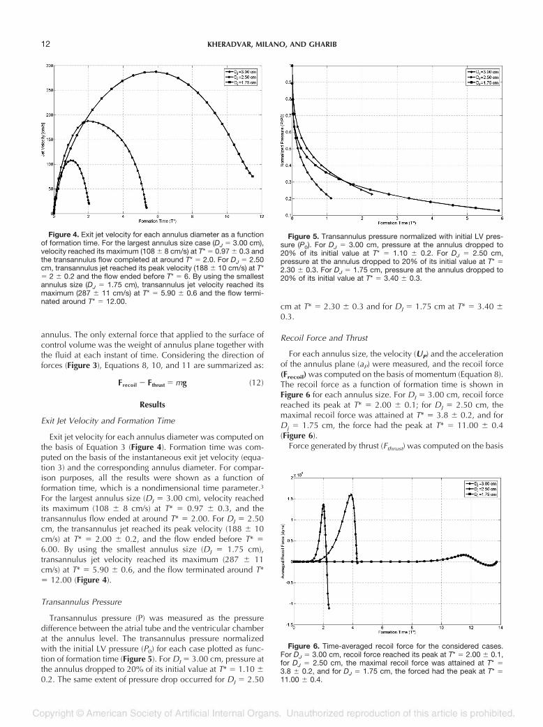
Figure 4. Exit jet velocity for each annulus diameter as a functionof formation time. For the largest annulus size case (DJ � 3.00 cm),velocity reached its maximum (108 � 8 cm/s) at T* � 0.97 � 0.3 andthe transannulus flow completed at around T* � 2.0. For DJ � 2.50cm, transannulus jet reached its peak velocity (188 � 10 cm/s) at T*� 2 � 0.2 and the flow ended before T* � 6. By using the smallestannulus size (DJ � 1.75 cm), transannulus jet velocity reached itsmaximum (287 � 11 cm/s) at T* � 5.90 � 0.6 and the flow termi-nated around T* � 12.00.
Figure 5. Transannulus pressure normalized with initial LV pres-sure (P0). For DJ � 3.00 cm, pressure at the annulus dropped to20% of its initial value at T* � 1.10 � 0.2. For DJ � 2.50 cm,pressure at the annulus dropped to 20% of its initial value at T* �2.30 � 0.3. For DJ � 1.75 cm, pressure at the annulus dropped to20% of its initial value at T* � 3.40 � 0.3.
Figure 6. Time-averaged recoil force for the considered cases.For DJ � 3.00 cm, recoil force reached its peak at T* � 2.00 � 0.1,for DJ � 2.50 cm, the maximal recoil force was attained at T* �3.8 � 0.2, and for DJ � 1.75 cm, the forced had the peak at T* �11.00 � 0.4.
12 KHERADVAR, MILANO, AND GHARIB

of exit jet velocity, annulus plane velocity, and pressure at theannulus.11 The magnitude of thrust can be compared with therecoil force in Figures 6 and 7. The thrust subtracted by instantweight of the atrial tube (mg) versus formation time is shown inFigure 7 for each annulus size. For Dj � 3.00 cm, thrustreached its peak at T* � 2.00 � 0.1; for Dj � 2.50 cm, themaximal thrust was attained at T* � 5.0 � 0.4, and for Dj �1.75 cm, the forced had the peak at T* � 11.00 � 0.3 (Figure7).
The recoil force was computed on the basis of Equation 10by tracking the annulus movement and transannulus flow withthe high-speed camera. Likewise, the thrust magnitude wascomputed by measuring variations in transannulus pressuretogether with the instantaneous jet velocity (Equation 11).
Considering that Frecoil and Fthrust were computed from differ-ent experimental techniques, the slight discrepancies in therelative timings of the two quantities could be attributed tomeasurement errors.
Circulation
Circulation of the ejected vortex ring was computed on thebasis of vorticity/velocity fields (Equations 6 and 7) obtainedfrom phase-averaged DPIV (Figure 8). The vortex ring pinchesoff when no additional energy or circulation is added to theleading vortex ring.3 By plotting the circulation versus forma-tion time, the incident of pinch-off (formation number) can bedefined as the formation time (T*) at which the circulationcurve saturates. Figure 9 compares the vortex ring circulationas a function of formation time for each annulus diameterstudied. It can be observed that the slope of the circulationcurve dramatically flattens at T* � 2.00 � 0.2 for Dj � 3.00cm. For Dj � 2.50 cm, the circulation curve starts to saturateat T* � 4.00 � 0.2. However, for Dj � 1.75 cm, the circulationcurve grows further than the former cases until T* � 13.00 �0.6, at which the circulation curve began to flatten (Figure 8).
Discussion
The timing of transannulus pressure drop was found to beinversely correlated with the size of the annulus, regardless ofthe similar pressure drop (� � 35 � 5) in ventricular chamber(Figure 5). Faster pressure drop for Dj � 3.00 cm resulted incompletion of transannulus flow (volume transfer) in a shorterformation time (Figure 3). For Dj � 2.50 cm and Dj � 1.75 cm,transannulus flow completed in T* � 5.40 � 0.5 and T* �11.30 � 0.6, respectively.
Although the volume of fluid transferred between two cham-bers were identical, the magnitude and the instant of the recoilforce was not the same for the annulus diameters studied(Figure 6). Therefore, the size of the annulus is a significantparameter in the dynamics of the annulus plane duringtransannulus flow. This study was designed in such a way thatno forces other than the ones generated by the transannulusflow can affect the annulus plane. As a matter of fact, wecomputed the thrust generated during propulsion (Figure 7)and the circulation of the ejected vortex ring for each case(Figure 8) to correlate with the annulus plane recoil force.
The final magnitude of thrust generated by each annulusdiameter was almost identical, whereas the time taken for eachannulus to reach the peak thrust was different (Figure 7). Thiswas the consequence of how momentum transferred from onechamber to another, and the peak incident showed a directrelation with the period needed to complete the volume trans-fer (Figures 4 and 7). Considering the recoil force (Figure 6), itcan be observed that it reached a peak (Figure 6) once thethrust force was close to its maximal magnitude (Figure 7), thusconfirming the same occurrence of the recoil force and thethrust.
The other parameter that was found to be changing withdifferent annulus sizes was the vortex ring circulation (Figure8). It has been observed that decreasing the size of the annulusincreases the final magnitude of the circulation (Figure 8).However, the formation time at which the magnitude of thecirculation saturated was different for each annulus size. The
Figure 7. Time-averaged thrust subtracted by the instantaneousweight of the water column in atrium. For DJ � 3.00 cm, thrustreached its peak at T* � 2.00 � 0.1, for DJ � 2.50 cm, the maximalthrust was attained at T* � 5.0 � 0.4, and for DJ � 1.75 cm, theforced had the peak at T* � 11.00 � 0.3.
Figure 8. Circulation of the ejected vortex ring obtained fromvorticity/velocity fields versus formation time for each annulus di-ameter. The slope of circulation curve dramatically flattens at T* �2.00 � 0.2 for DJ � 3.00 cm. For DJ � 2.50 cm, the circulation curvestarts to saturate at T* � 4.00 � 0.2, and for DJ � 1.75 cm, thecirculation curve grew until T* � 13.00 � 0.6, at which the circula-tion curve began to flatten.
13VORTEX RING FORMATION AND MITRAL ANNULUS DYNAMICS DURING VENTRICULAR RAPID FILLING

larger the annulus diameter, the sooner the circulation satu-rates.
Considering the trend of vortex ring circulation and theincident of maximal recoil force (Figures 6 and 8) for DJ � 3.00cm and DJ � 2.50 cm, it can be observed that the peak recoilforce occurred at the formation time (T* � 2.00 � 0.1 and T*� 3.8 � 0.2, respectively) in which circulation was saturating(T* � 2.00 � 0.2 and T* � 4.00 � 0.2, respectively). For thecase DJ � 1.75 cm, the peak recoil force occurred at T* �11.30 � 0.3, later than the formation time at which circulationsaturated (T* � 10.00 � 0.3).
It has been shown before that a vortex ring is consideredpinched off when the circulation does not increase, whichmeans that the leading vortex ring does not receive anyadditional energy from the starting jet.4 In the present study,it was found that for DJ � 3.00 cm and DJ � 2.50 cm, bothmaximal recoil force and maximal jet thrust occurred at theformation time in which vortex ring circulation was satu-rated. Figure 9 shows a snapshot of the vorticity field ob-tained by phase-averaged DPIV for each case at the onset ofpeak recoil force. The maximal value of the recoil force wasattained in the case with DJ � 2.50 cm at T* � 3.8 � 0.2.In this case, the formation time at which the recoil-forcepeak occurred was in the range of the formation numberdefined by Gharib et al. This implies that all the circulationproduced in the pulsed jet went into the leading vortex ring,thereby maximizing the recoil force. This was also con-firmed by the vorticity plot in Figure 9B, which shows thatthe leading vortex pinches off at this formation time.
For the largest annulus (DJ � 3.00 cm), the recoil forcehad a peak at T* � 2.00 � 0.1. However, the peak recoilforce was smaller than the medium-sized annulus (DJ �2.50 cm). The vorticity field in Figure 9A shows that at thisformation time, the leading vortex was not yet pinched off,whereas it was hitting the bottom wall. This prevented thefurther growth of the leading vortex ring, thereby limitingthe corresponding recoil force and further increase in mag-nitude of circulation (Figure 8). For the smallest annulus (DJ
� 1.75 cm), the recoil force had a peak at T* � 11.30 � 0.3,and the peak value was the smallest among all the threeannulus sizes. By comparing Figures 6 and 8, it can beinferred that at the incident of recoil force (T* � 11.30 �0.3), the circulation curve has been flattened earlier andthus the vortex ring was already pinched off (T* � 10.00 �0.3). This assumption was also confirmed by the corre-sponding vorticity field at the onset of peak recoil force
plotted in Figure 9C. In this case, it was apparent that thevortex ring has already hit the bottom before and the vor-ticity is no longer entrained from the shear layer region ofthe trailing jet. The recoil force in this case was the result ofthe trailing jet rather than the consequence of vortex ring pinch-off, and that might be a reason for its much smaller magnitudecompared with the other two annulus sizes (Figure 6).
Equivalent Piston-Cylinder Setup
Starting jets are typically created by using piston-cylindersetup. To relate the results of the present study to the otherknown results for a standard piston-cylinder setup, an equiv-alent stroke ratio (SR) was defined for each annulus size as theratio of the length of jet (LJ) to the jet diameter (DJ). Thesequantities were obtained on the basis of conservation of massand equating volumes of fluid exchanged between the twochambers:
Vejected ��
4DA
2 � LA ��
4DJ
2 � LJ (13)
where Vejected is the total volume of fluid ejected from atrialtube in a single run, LA is the water level height change inthe atrial tube (LA � 1.00 cm; constant for all the cases), andLJ is the nominal jet length or the distance traveled by apiston with diameter DJ ejecting the same volume from anequivalent piston-cylinder setup. In other words, if the totalejected volume is kept constant, the equivalent SR can beattributed to an equivalent experiment performed with apiston-cylinder setup in which the total volume of ejectedfluid is the same.
Based on Equation 13, the equivalent stroke ratios were 9.14for DJ � 1.75 cm, 3.12 for DJ � 2.50 cm, and 1.80 for DJ �3.00 cm. The equivalent piston-cylinder setup that generatedthe maximal recoil force (Figure 6) had an SR of 3.12, which,among all cases, was the closest one to the ratio that Kruegerand Gharib13 found to generate maximal averaged thrust. Itwas also found that the recoil force was maximized at aformation time close to the equivalent SR for each case (Figure6). This was expected because the total thrust for the threecases was conserved (Figure 7) due to the constant ejectedvolume.13 However, the magnitude of the peak recoil forcewas different in each case (Figure 6).
Figure 9. Snapshot of the vorticity field obtained by DPIV for different cases at the onset of peak recoil force. (A) DJ � 3.00 cm: In this case,the vorticity field shows that the leading vortex was not yet pinched off (T* � 2.00 � 0.1), whereas it was hitting the bottom wall. Thisprevented further growth of the leading vortex ring. (B) DJ � 2.50 cm: In this case, the leading vortex has just pinched off (T* � 3.8 � 0.2).(C) DJ � 1.75 cm: In this case, the recoil force had a peak at T* � 11.00 � 0.4. The corresponding vorticity field shows that there was onlya trailing jet, meaning that the leading vortex ring had already been pinched off.
14 KHERADVAR, MILANO, AND GHARIB

Physiologic Significance
It has been shown previously that the normal pattern of LVfilling would be altered because of the diastolic dysfunction,which occurs during the development of heart failure.29–31
This variation in transmitral flow would also be reflected indiastolic motion of the mitral annulus measured by Dopplertissue imaging (DTI).32 DTI of the mitral annulus has beenrecognized as an effective indicator of LV function in humanheart.33,34 The peak velocity of the mitral annulus away fromthe apex during early diastole (EM), indicating the rate oflongitudinal expansion of the LV, is reduced in patients withimpaired diastolic relaxation.35
In the present study, we showed that in a simplified modelof the left heart, the variation in jet stroke ratio can bereflected in the dynamics of the mitral annulus plane. Morespecifically, we found that for a physiologic base-apex dis-tance and an annulus diameter of 2.50 cm, which closelyapproximates the normal annulus diameter in adults, if thephysiologic pressure decay applied, the annulus plane re-coil force would be maximal at the time in which the vortexring pinches off. In a real heart, the complex geometry andthe viscoelastic properties of the ventricular chamber aswell as the wall-flow interaction and viscosity are alsoresponsible for variations in dynamics of mitral annulus.However, the above-mentioned parameters directly influ-ence transmitral flow and the formed vortex ring.
Almost all the patients with idiopathic dilated cardiomy-opathy have a significantly large mitral annulus.36 There-fore, as a result the transmitral jet, stroke ratio would bedifferent from a normal LV. In a recent study, Mori et al.37
showed that the peak mitral annulus velocity also would belower than normal in cases with dilated cardiomyopathy.The results of their study is congruent with our observation,confirming that by increasing the annulus diameter morethan 2.50 cm, even if a physiologic LV pressure drop isapplied, the annulus recoil is not optimum when comparedwith normal.
On the other hand, another recent study38 has demonstratedthat the LV long-axis function, evaluated by DTI in patients withpure mitral stenosis, is significantly impaired despite the normalglobal systolic function. In this case, if the LV pressure dropduring diastole remains constant, the transmitral jet stroke ratiowill increase. This observation is also consistent with our studycorroborating that by decreasing the mitral annulus diameter,despite the fact that the transmitral jet velocity increases, theannulus recoil force will be smaller than the normal case.
Conclusion
The present in vitro study confirms the presence of a vortexring during rapid filling phase of diastole and implies that theprocess of vortex ring formation can influence mitral annulusdynamics. Additionally, this study suggests that vortex ringformation can be used as an index for assessment of LV func-tion during diastole and as a factor that should be consideredin design and implementing cardiac prosthetics devices.
Limitations
In this study, we did not consider the active myocardialcontractions, interaction of valve leaflet and flow, and the
blood viscosity on formation of the vortex ring. Works are inprogress to design and use an actively contracting chamber formimicking cardiac expansion, using Bioprosthetic heart valvesin mitral position and blood analogs for viscose flow. Anotherlimitation of this study was using a phase-averaged DPIVtechnique, which slightly increased the error because of thefast nature of the experiment. Works are in progress to usecontinuous laser for illumination and high-speed cameras forstereo-PIV to obtain more accurate results.
Acknowledgments
The authors are grateful to Prof. Anthony Leonard for the usefuldiscussions on control volume analysis and to Prof. Michael Dickinsonand his group for using their high-speed cameras.
References
1. Didden N: On the formation of vortex rings: rolling-up and pro-duction of circulation. Z Angew Math Phys 30: 101, 1979.
2. Shariff K, Leonard A: Vortex rings. Annu Rev Fluid Mech 24: 235, 1992.3. Gharib M, Rambod E, Shariff K: A universal time scale for vortex
ring formation. J Fluid Mech 360: 121–140, 1998.4. Rosenfeld M, Rambod E, Gharib M: Circulation and formation num-
ber of laminar vortex rings. Fluid Mech 376: 297–318, 1998.5. Bellhouse BJ: Fluid mechanics of a model mitral valve and left
ventricle. Cardiovasc Res 6: 199–210, 1972.6. Reul H, Talukder N, Muller W: Fluid mechanics of the natural
mitral valve. J Biomech 14: 361–372, 1981.7. Kim WY, Bisgaard T, Nielsen SL, et al: Two-dimensional mitral
flow velocity profiles in pig models using epicardial echoDoppler Cardiography. J Am Coll Cardiol 24: 532–545, 1994.
8. Vierendeels JA, Dick E, Verdonck PR: Hydrodynamics of colorM-mode Doppler flow wave propagation velocity V(p): a com-puter study: J Am Soc Echocardiogr 15: 219–224, 2002.
9. Kim WY, Walker PG, Pedersen EM, et al: Left ventricular bloodflow patterns in normal subjects: a quantitative analysis bythree dimensional magnetic resonance velocity mapping. J AmColl Cardiol 26: 224–238, 1995.
10. Kilner PJ, Yang GZ, Wilkes AJ, et al: Asymmetric redirection offlow through the heart. Nature 404: 759–761, 2000.
11. Johari H, Rixon GS: Effects of pulsing on a vortex generator jet.AIAA J 41: 2309–2315, 2003.
12. Cater JE, Soria J: The evolution of round zero-net-mass-flux jets.J Fluid Mech 472: 167–200, 2002.
13. Krueger PS, Gharib M: The significance of vortex ring formation tothe impulse and thrust of a starting jet. Physics Fluids 15:1271–1281, 2003.
14. Steen T, Steen S: Filling of a model left ventricle studied by colourM mode Doppler. Cardiovasc Res 28: 1821–1827, 1994.
15. Baccani B, Domenichini F, Pedrizzetti G, Tonti G: Fluid dynamicsof the left ventricular filling in dilated cardiomyopathy. J Bio-mech 35: 665–671, 2002.
16. Weiss JL, Fredrisen JW, Weisfeldt ML: Hemodynamic determi-nants of the time course of fall in canine left ventricular pres-sure. J Clin Invest 58: 751–760, 1976.
17. Yellin EL, Nikolic S, Frater RWM: Left-ventricular filling dynamicsand diastolic function. Prog Cardiovasc Dis 32: 247–271, 1990.
18. Yellin EL, Hori M, Yoran C, et al: Left-ventricular relaxation in thefilling and nonfilling intact canine heart. Am J Cardiol 250:H620–H629, 1986.
19. Rodriguez F, Langer F, Harrington KB, et al: Importance of mitralvalve second-order chordae for left ventricular geometry, wallthickening mechanics, and global systolic function. Circulation110: II-115-II-122, 2004.
20. Standring S: Gray’s Anatomy: The Anatomical Basis of ClinicalPractice. Oxford: Churchill Livingstone; 39th ed, 2004.
21. Dong SJ, Hees PS, Siu CO, et al: MRI assessment of LV relaxationby untwisting rate: a new isovolumic phase measure of t. Am JPhysiol Heart Circ Physiol 281: H2002–H2009, 2001.
22. Ommen SR, Nishimura RA, Appleton CP, et al: Clinical utility of
15VORTEX RING FORMATION AND MITRAL ANNULUS DYNAMICS DURING VENTRICULAR RAPID FILLING

Doppler echocardiography and tissue Doppler imaging in theestimation of left ventricular filling pressures: a comparativesimultaneous Doppler-catheterization study. Circulation 102:1788–1794, 2000.
23. Guyton AC, Hall JE. Textbook of Medical Physiology. 10th ed,Philadelphia, PA: WB Saunders Company, 2000.
24. Brutsaert DL, Rademakera FE, Sys SU: Triple control of relaxation:implications in cardiac disease. Circulation 69: 190–196, 1984.
25. Brutsaert DL, Sys SU: Relaxation and diastole of the heart. PhysiolRev 69: 1228–1315, 1989.
26. Gilbert JC, Glantz SA: Determinants of left ventricular filling andof the diastolic pressure/volume-relationship. Circ Res 64: 827–852, 1989.
27. Willert CE, Gharib M: Digital particle image velocimetry. ExpFluids 10: 181–193, 1991.
28. Kheradvar A, Kasalko J, Johnson D, Gharib M: An in vitro study ofchanging profile heights in mitral bioprostheses and their influ-ence on flow. ASAIO J 52: 34–38, 2005.
29. Appleton CP: Doppler assessment of left ventricular diastolic func-tion: the refinements continue. J Am Coll Cardiol 21: 1697–1700, 1993.
30. Ohno M, Cheng CP, Little WC: Mechanism of altered patterns ofleft ventricular filling during the development of congestiveheart failure. Circulation 89: 2241–2250, 1994.
31. Nishimura RA, Tajik AJ: Evaluation of diastolic filling of left ven-
tricle in health and disease: Doppler echocardiography is theclinician’s Rosetta stone. J Am Coll Cardiol 30: 8–18, 1997.
32. Nagueh SF: Noninvasive evaluation of hemodynamics by Dopplerechocardiography. Curr Opin Cardiol 14: 217–224, 1999.
33. Nagueh SF, Middleton KJ, Kopelen HA, et al: Doppler tissueimaging: a noninvasive technique for evaluation of left ventric-ular relaxation and estimation of filling pressures. J Am CollCardiol 30: 1527–1533, 1997.
34. Sanderson JE, Wang M, Yu CM: Tissue Doppler imaging forpredicting outcome in patients with cardiovascular disease.Curr Opin Cardiol 19: 458–463, 2004.
35. Hasegawa H, Little WC, Ohno M, et al: Diastolic mitral annularvelocity during the development of heart failure. J Am CollCardiol 41: 1590–1597, 2003.
36. Kwan J, Shiota T, Agler DA, et al: Geometric differences of the mitralapparatus between ischemic and dilated cardiomyopathy withsignificant mitral regurgitation: real-time three-dimensional echo-cardiography study. Circulation 107: 1135–1140, 2003.
37. Mori K, Edagawa T, Inoue M, et al: Peak negative myocardialvelocity gradient and wall-thickening velocity during early di-astole are noninvasive parameters of left ventricular diastolicfunction in patients with Duchenne’s progressive muscular dys-trophy. J Am Soc Echocardiogr 17: 322–329, 2004.
38. Ozer N, Can I, Atalar E, et al: Left ventricular long-axis function isreduced in patients with rheumatic mitral stenosis. Echocardi-ography 21: 107–112, 2004.
16 KHERADVAR, MILANO, AND GHARIB