Cornell University Autonomous Underwater Vehicle: Design...
10
Cornell University Autonomous Underwater Vehicle: Design and Implementation of the Ragnar¨ ok AUV Markus Burkardt (leader), Linda Barron, Thomas Brooks, Mark Bunney, Corey Chang, Pawit Chayanupatkul, Patrick Dear, Xiaoxi Du, Kent Esslinger, Scott Franklin, Zheng Fu, Edward Gong, Peter Gu, Melissa Hamada, Jeff Heidel, Kylar Henderson, Napon Jatusiripitak, Jisha Kambo, Michael Kaplan, David Kelly, Moonyoung Lee, Kevin Lee, Kevin Lei, Noah Levy, Yizhou Luo, Michael Mahoney, Alexandru Malcoci, Lavina Ng, Zachary Porter, Michael Ross, Christos Sideris, Jeffery Sim, Hilary Soohoo, Alexander Spitzer, Edward Szoka, Ellen Thiel, Alex Ting, Samuel Tome, Peter Tseng, Baturay Turkmen, Andre Vazquez, Alvin Wijaya, Cheng Xing, and Rene Zhang. Abstract—The CUAUV Ragnar¨ ok is a new littoral autonomous underwater vehicle (AUV) developed by a team of undergraduate students at Cornell University. Built in a ten month design cycle, the vehicle was fully modeled using CAD software and manufactured almost entirely in-house. With a num- ber of new innovations, Ragnar¨ ok presents a stronger, lighter, and more agile platform with increased ca- pabilities over previous vehicles. New advancements include a stronger yet extremely light frame, an improved electrical system, and significant software changes which yield improved mission reliability and robustness. Ragnar¨ ok’s sensor suite includes three color cameras, compasses, inertial measurement units (IMUs), a Teledyne RDI Explorer Doppler velocity log, a depth sensor, an internal pressure sensor, and a hydrophone array. Returning features include the single-hull cantilevered electronics rack, a vacuum- assisted sealing system, hot-swappable battery pods, pneumatic actuators, unified serial communications, and flexible mission software architecture. I. I NTRODUCTION T HE Cornell University Autonomous Un- derwater Vehicle team’s main objective is to design and build an autonomous underwa- ter vehicle (AUV) for the annual AUVSI and ONR International RoboSub Competition. The competition is held in July at the TRANSDEC facility, part of SPAWAR Systems Center Pa- cific in San Diego, California. The competition is designed to challenge student-built AUVs with tasks that simulate real-world missions. These tasks include visual and acoustic detec- tion of competition elements, navigation, obsta- cle avoidance, and object manipulation tasks. Competition elements range from shape and color recognition to torpedo firing and turning a steering wheel. Each of these tasks must be completed by the vehicle independent of human control or interaction. In order to complete the task of building a vehicle that is capable of completing all mission tasks and meeting all requirements, the team is divided into Mechanical, Electrical, Software and Business/PR subteams. II. DESIGN OVERVIEW The 2012-2013 vehicle, Ragnar¨ ok, is a hov- ering, littoral-class AUV designed primarily to compete in the AUVSI/ONR RoboSub compe- tition. The design is similar to that of work or observation class remotely operated vehicles (ROVs), designed for high functionality and fine-grained positional control. This design was selected to best meet the challenges set forth by the competition. Ragnar¨ ok is an improvement over previous vehicles in robustness, weight, and ease of as- sembly. The robustness was improved through more extensive electrical testing and rigorous Cornell University Autonomous Underwater Vehicle 1
Transcript of Cornell University Autonomous Underwater Vehicle: Design...
Cornell University Autonomous UnderwaterVehicle: Design and Implementation of the
Ragnarok AUVMarkus Burkardt (leader), Linda Barron, Thomas Brooks, Mark Bunney, Corey Chang, Pawit Chayanupatkul,Patrick Dear, Xiaoxi Du, Kent Esslinger, Scott Franklin, Zheng Fu, Edward Gong, Peter Gu, Melissa Hamada,
Jeff Heidel, Kylar Henderson, Napon Jatusiripitak, Jisha Kambo, Michael Kaplan, David Kelly, Moonyoung Lee,Kevin Lee, Kevin Lei, Noah Levy, Yizhou Luo, Michael Mahoney, Alexandru Malcoci, Lavina Ng, ZacharyPorter, Michael Ross, Christos Sideris, Jeffery Sim, Hilary Soohoo, Alexander Spitzer, Edward Szoka, Ellen
Thiel, Alex Ting, Samuel Tome, Peter Tseng, Baturay Turkmen, Andre Vazquez, Alvin Wijaya, Cheng Xing, andRene Zhang.
Abstract—The CUAUV Ragnarok is a new littoralautonomous underwater vehicle (AUV) developedby a team of undergraduate students at CornellUniversity. Built in a ten month design cycle, thevehicle was fully modeled using CAD software andmanufactured almost entirely in-house. With a num-ber of new innovations, Ragnarok presents a stronger,lighter, and more agile platform with increased ca-pabilities over previous vehicles. New advancementsinclude a stronger yet extremely light frame, animproved electrical system, and significant softwarechanges which yield improved mission reliability androbustness. Ragnarok’s sensor suite includes threecolor cameras, compasses, inertial measurement units(IMUs), a Teledyne RDI Explorer Doppler velocitylog, a depth sensor, an internal pressure sensor, anda hydrophone array. Returning features include thesingle-hull cantilevered electronics rack, a vacuum-assisted sealing system, hot-swappable battery pods,pneumatic actuators, unified serial communications,and flexible mission software architecture.
I. INTRODUCTION
THE Cornell University Autonomous Un-derwater Vehicle team’s main objective is
to design and build an autonomous underwa-ter vehicle (AUV) for the annual AUVSI andONR International RoboSub Competition. Thecompetition is held in July at the TRANSDECfacility, part of SPAWAR Systems Center Pa-cific in San Diego, California. The competitionis designed to challenge student-built AUVs
with tasks that simulate real-world missions.These tasks include visual and acoustic detec-tion of competition elements, navigation, obsta-cle avoidance, and object manipulation tasks.Competition elements range from shape andcolor recognition to torpedo firing and turninga steering wheel. Each of these tasks mustbe completed by the vehicle independent ofhuman control or interaction.
In order to complete the task of buildinga vehicle that is capable of completing allmission tasks and meeting all requirements,the team is divided into Mechanical, Electrical,Software and Business/PR subteams.
II. DESIGN OVERVIEW
The 2012-2013 vehicle, Ragnarok, is a hov-ering, littoral-class AUV designed primarily tocompete in the AUVSI/ONR RoboSub compe-tition. The design is similar to that of workor observation class remotely operated vehicles(ROVs), designed for high functionality andfine-grained positional control. This design wasselected to best meet the challenges set forth bythe competition.
Ragnarok is an improvement over previousvehicles in robustness, weight, and ease of as-sembly. The robustness was improved throughmore extensive electrical testing and rigorous
Cornell University Autonomous Underwater Vehicle 1
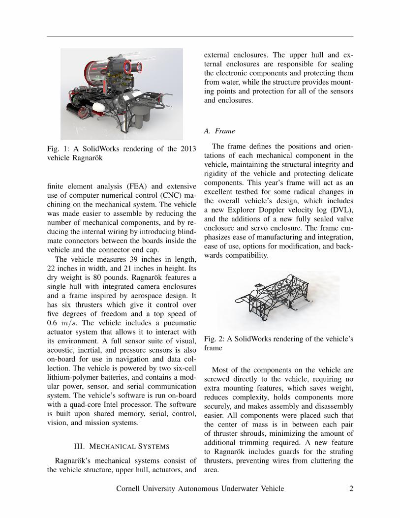
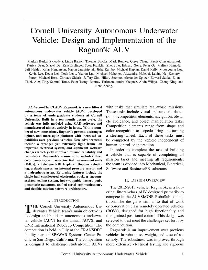
Fig. 1: A SolidWorks rendering of the 2013vehicle Ragnarok
finite element analysis (FEA) and extensiveuse of computer numerical control (CNC) ma-chining on the mechanical system. The vehiclewas made easier to assemble by reducing thenumber of mechanical components, and by re-ducing the internal wiring by introducing blind-mate connectors between the boards inside thevehicle and the connector end cap.
The vehicle measures 39 inches in length,22 inches in width, and 21 inches in height. Itsdry weight is 80 pounds. Ragnarok features asingle hull with integrated camera enclosuresand a frame inspired by aerospace design. Ithas six thrusters which give it control overfive degrees of freedom and a top speed of0.6 m/s. The vehicle includes a pneumaticactuator system that allows it to interact withits environment. A full sensor suite of visual,acoustic, inertial, and pressure sensors is alsoon-board for use in navigation and data col-lection. The vehicle is powered by two six-celllithium-polymer batteries, and contains a mod-ular power, sensor, and serial communicationsystem. The vehicle’s software is run on-boardwith a quad-core Intel processor. The softwareis built upon shared memory, serial, control,vision, and mission systems.
III. MECHANICAL SYSTEMS
Ragnarok’s mechanical systems consist ofthe vehicle structure, upper hull, actuators, and
external enclosures. The upper hull and ex-ternal enclosures are responsible for sealingthe electronic components and protecting themfrom water, while the structure provides mount-ing points and protection for all of the sensorsand enclosures.
A. Frame
The frame defines the positions and orien-tations of each mechanical component in thevehicle, maintaining the structural integrity andrigidity of the vehicle and protecting delicatecomponents. This year’s frame will act as anexcellent testbed for some radical changes inthe overall vehicle’s design, which includesa new Explorer Doppler velocity log (DVL),and the additions of a new fully sealed valveenclosure and servo enclosure. The frame em-phasizes ease of manufacturing and integration,ease of use, options for modification, and back-wards compatibility.
Fig. 2: A SolidWorks rendering of the vehicle’sframe
Most of the components on the vehicle arescrewed directly to the vehicle, requiring noextra mounting features, which saves weight,reduces complexity, holds components moresecurely, and makes assembly and disassemblyeasier. All components were placed such thatthe center of mass is in between each pairof thruster shrouds, minimizing the amount ofadditional trimming required. A new featureto Ragnarok includes guards for the strafingthrusters, preventing wires from cluttering thearea.
Cornell University Autonomous Underwater Vehicle 2
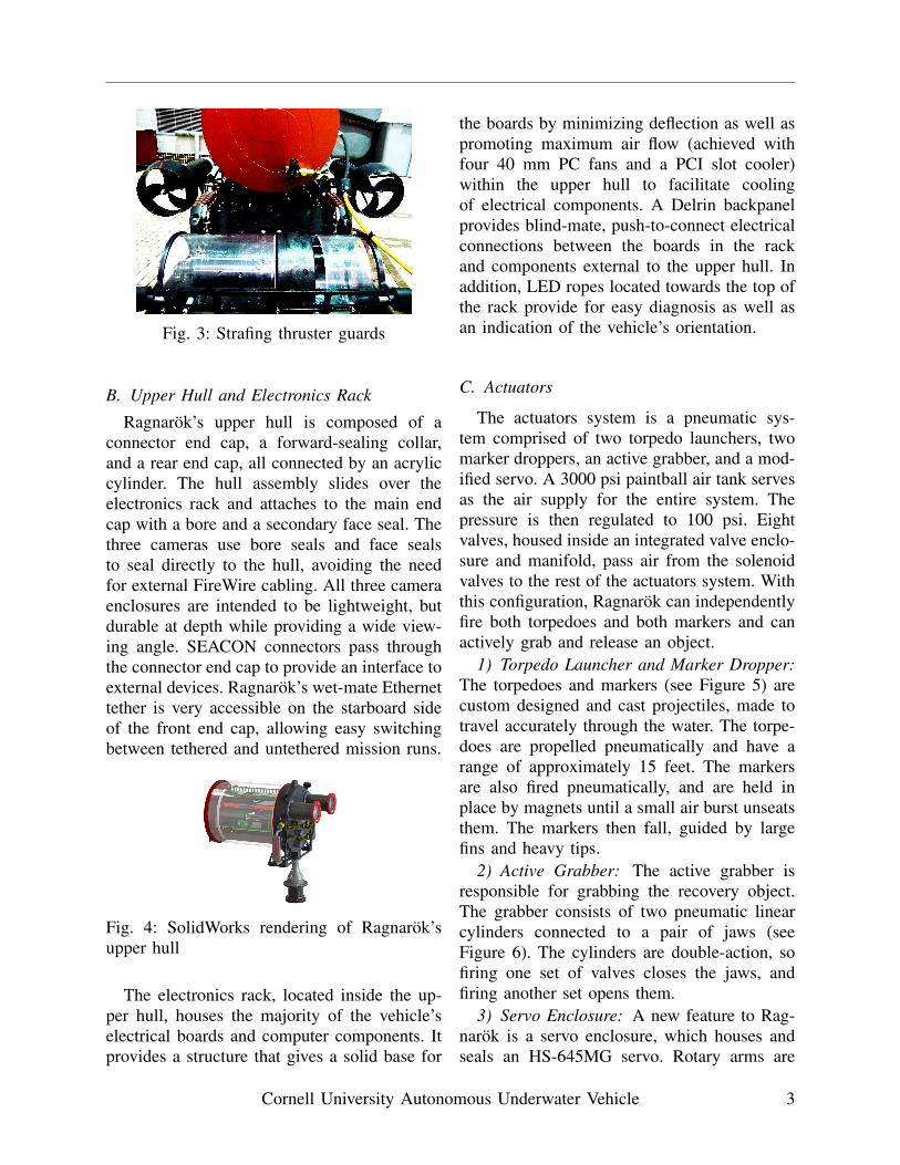
Fig. 3: Strafing thruster guards
B. Upper Hull and Electronics Rack
Ragnarok’s upper hull is composed of aconnector end cap, a forward-sealing collar,and a rear end cap, all connected by an acryliccylinder. The hull assembly slides over theelectronics rack and attaches to the main endcap with a bore and a secondary face seal. Thethree cameras use bore seals and face sealsto seal directly to the hull, avoiding the needfor external FireWire cabling. All three cameraenclosures are intended to be lightweight, butdurable at depth while providing a wide view-ing angle. SEACON connectors pass throughthe connector end cap to provide an interface toexternal devices. Ragnarok’s wet-mate Ethernettether is very accessible on the starboard sideof the front end cap, allowing easy switchingbetween tethered and untethered mission runs.
Fig. 4: SolidWorks rendering of Ragnarok’supper hull
The electronics rack, located inside the up-per hull, houses the majority of the vehicle’selectrical boards and computer components. Itprovides a structure that gives a solid base for
the boards by minimizing deflection as well aspromoting maximum air flow (achieved withfour 40 mm PC fans and a PCI slot cooler)within the upper hull to facilitate coolingof electrical components. A Delrin backpanelprovides blind-mate, push-to-connect electricalconnections between the boards in the rackand components external to the upper hull. Inaddition, LED ropes located towards the top ofthe rack provide for easy diagnosis as well asan indication of the vehicle’s orientation.
C. Actuators
The actuators system is a pneumatic sys-tem comprised of two torpedo launchers, twomarker droppers, an active grabber, and a mod-ified servo. A 3000 psi paintball air tank servesas the air supply for the entire system. Thepressure is then regulated to 100 psi. Eightvalves, housed inside an integrated valve enclo-sure and manifold, pass air from the solenoidvalves to the rest of the actuators system. Withthis configuration, Ragnarok can independentlyfire both torpedoes and both markers and canactively grab and release an object.
1) Torpedo Launcher and Marker Dropper:The torpedoes and markers (see Figure 5) arecustom designed and cast projectiles, made totravel accurately through the water. The torpe-does are propelled pneumatically and have arange of approximately 15 feet. The markersare also fired pneumatically, and are held inplace by magnets until a small air burst unseatsthem. The markers then fall, guided by largefins and heavy tips.
2) Active Grabber: The active grabber isresponsible for grabbing the recovery object.The grabber consists of two pneumatic linearcylinders connected to a pair of jaws (seeFigure 6). The cylinders are double-action, sofiring one set of valves closes the jaws, andfiring another set opens them.
3) Servo Enclosure: A new feature to Rag-narok is a servo enclosure, which houses andseals an HS-645MG servo. Rotary arms are
Cornell University Autonomous Underwater Vehicle 3
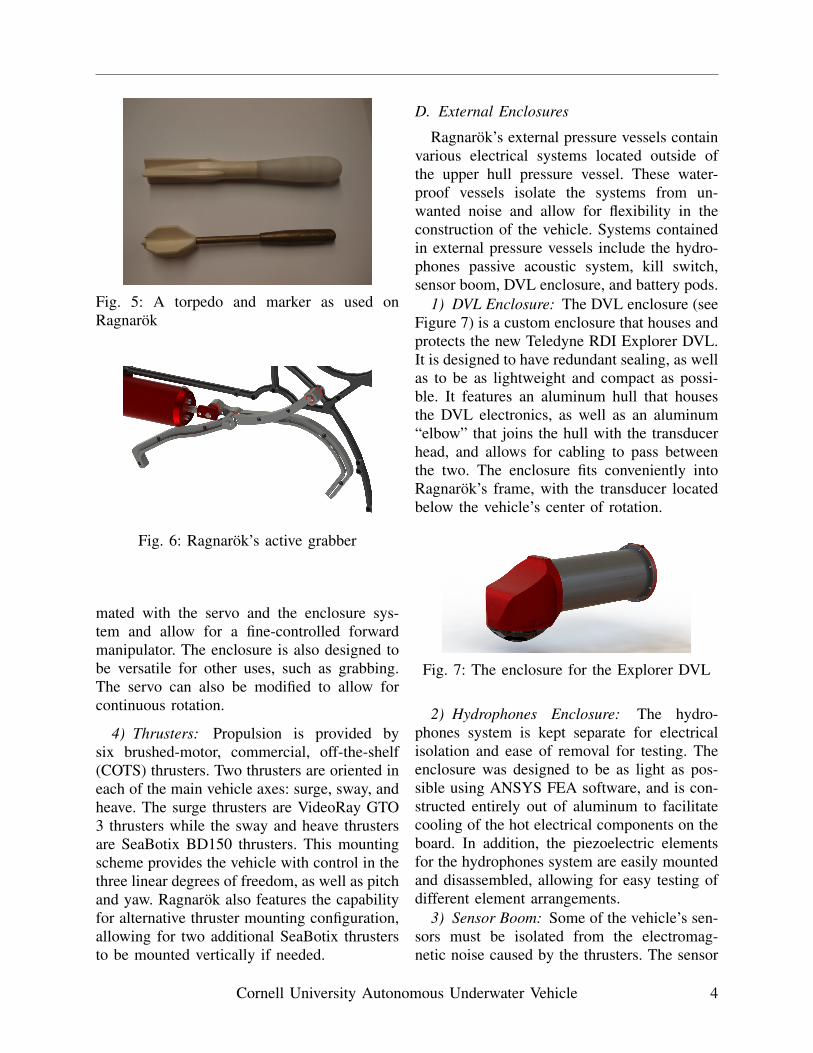
Fig. 5: A torpedo and marker as used onRagnarok
Fig. 6: Ragnarok’s active grabber
mated with the servo and the enclosure sys-tem and allow for a fine-controlled forwardmanipulator. The enclosure is also designed tobe versatile for other uses, such as grabbing.The servo can also be modified to allow forcontinuous rotation.
4) Thrusters: Propulsion is provided bysix brushed-motor, commercial, off-the-shelf(COTS) thrusters. Two thrusters are oriented ineach of the main vehicle axes: surge, sway, andheave. The surge thrusters are VideoRay GTO3 thrusters while the sway and heave thrustersare SeaBotix BD150 thrusters. This mountingscheme provides the vehicle with control in thethree linear degrees of freedom, as well as pitchand yaw. Ragnarok also features the capabilityfor alternative thruster mounting configuration,allowing for two additional SeaBotix thrustersto be mounted vertically if needed.
D. External Enclosures
Ragnarok’s external pressure vessels containvarious electrical systems located outside ofthe upper hull pressure vessel. These water-proof vessels isolate the systems from un-wanted noise and allow for flexibility in theconstruction of the vehicle. Systems containedin external pressure vessels include the hydro-phones passive acoustic system, kill switch,sensor boom, DVL enclosure, and battery pods.
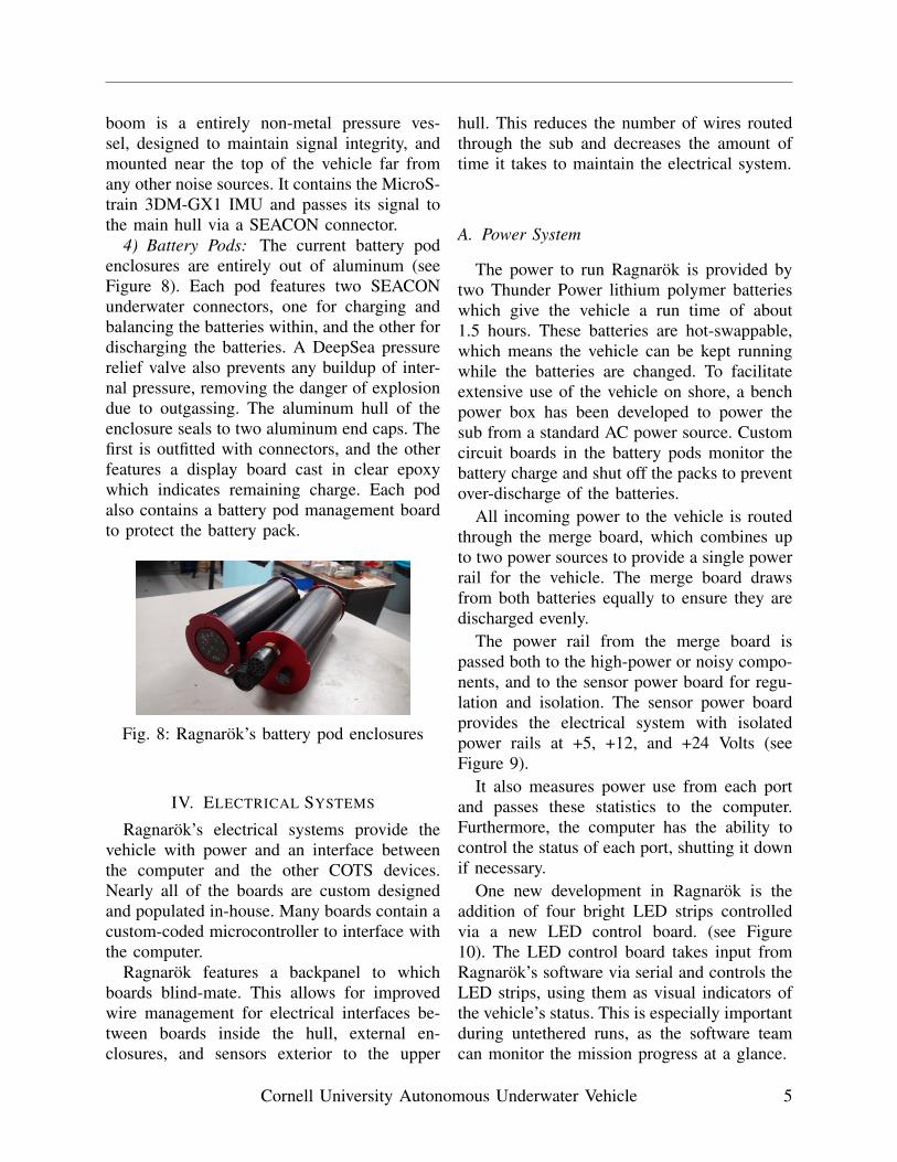
1) DVL Enclosure: The DVL enclosure (seeFigure 7) is a custom enclosure that houses andprotects the new Teledyne RDI Explorer DVL.It is designed to have redundant sealing, as wellas to be as lightweight and compact as possi-ble. It features an aluminum hull that housesthe DVL electronics, as well as an aluminum“elbow” that joins the hull with the transducerhead, and allows for cabling to pass betweenthe two. The enclosure fits conveniently intoRagnarok’s frame, with the transducer locatedbelow the vehicle’s center of rotation.
Fig. 7: The enclosure for the Explorer DVL
2) Hydrophones Enclosure: The hydro-phones system is kept separate for electricalisolation and ease of removal for testing. Theenclosure was designed to be as light as pos-sible using ANSYS FEA software, and is con-structed entirely out of aluminum to facilitatecooling of the hot electrical components on theboard. In addition, the piezoelectric elementsfor the hydrophones system are easily mountedand disassembled, allowing for easy testing ofdifferent element arrangements.
3) Sensor Boom: Some of the vehicle’s sen-sors must be isolated from the electromag-netic noise caused by the thrusters. The sensor
Cornell University Autonomous Underwater Vehicle 4
boom is a entirely non-metal pressure ves-sel, designed to maintain signal integrity, andmounted near the top of the vehicle far fromany other noise sources. It contains the MicroS-train 3DM-GX1 IMU and passes its signal tothe main hull via a SEACON connector.
4) Battery Pods: The current battery podenclosures are entirely out of aluminum (seeFigure 8). Each pod features two SEACONunderwater connectors, one for charging andbalancing the batteries within, and the other fordischarging the batteries. A DeepSea pressurerelief valve also prevents any buildup of inter-nal pressure, removing the danger of explosiondue to outgassing. The aluminum hull of theenclosure seals to two aluminum end caps. Thefirst is outfitted with connectors, and the otherfeatures a display board cast in clear epoxywhich indicates remaining charge. Each podalso contains a battery pod management boardto protect the battery pack.
Fig. 8: Ragnarok’s battery pod enclosures
IV. ELECTRICAL SYSTEMS
Ragnarok’s electrical systems provide thevehicle with power and an interface betweenthe computer and the other COTS devices.Nearly all of the boards are custom designedand populated in-house. Many boards contain acustom-coded microcontroller to interface withthe computer.
Ragnarok features a backpanel to whichboards blind-mate. This allows for improvedwire management for electrical interfaces be-tween boards inside the hull, external en-closures, and sensors exterior to the upper
hull. This reduces the number of wires routedthrough the sub and decreases the amount oftime it takes to maintain the electrical system.
A. Power System
The power to run Ragnarok is provided bytwo Thunder Power lithium polymer batterieswhich give the vehicle a run time of about1.5 hours. These batteries are hot-swappable,which means the vehicle can be kept runningwhile the batteries are changed. To facilitateextensive use of the vehicle on shore, a benchpower box has been developed to power thesub from a standard AC power source. Customcircuit boards in the battery pods monitor thebattery charge and shut off the packs to preventover-discharge of the batteries.
All incoming power to the vehicle is routedthrough the merge board, which combines upto two power sources to provide a single powerrail for the vehicle. The merge board drawsfrom both batteries equally to ensure they aredischarged evenly.
The power rail from the merge board ispassed both to the high-power or noisy compo-nents, and to the sensor power board for regu-lation and isolation. The sensor power boardprovides the electrical system with isolatedpower rails at +5, +12, and +24 Volts (seeFigure 9).
It also measures power use from each portand passes these statistics to the computer.Furthermore, the computer has the ability tocontrol the status of each port, shutting it downif necessary.
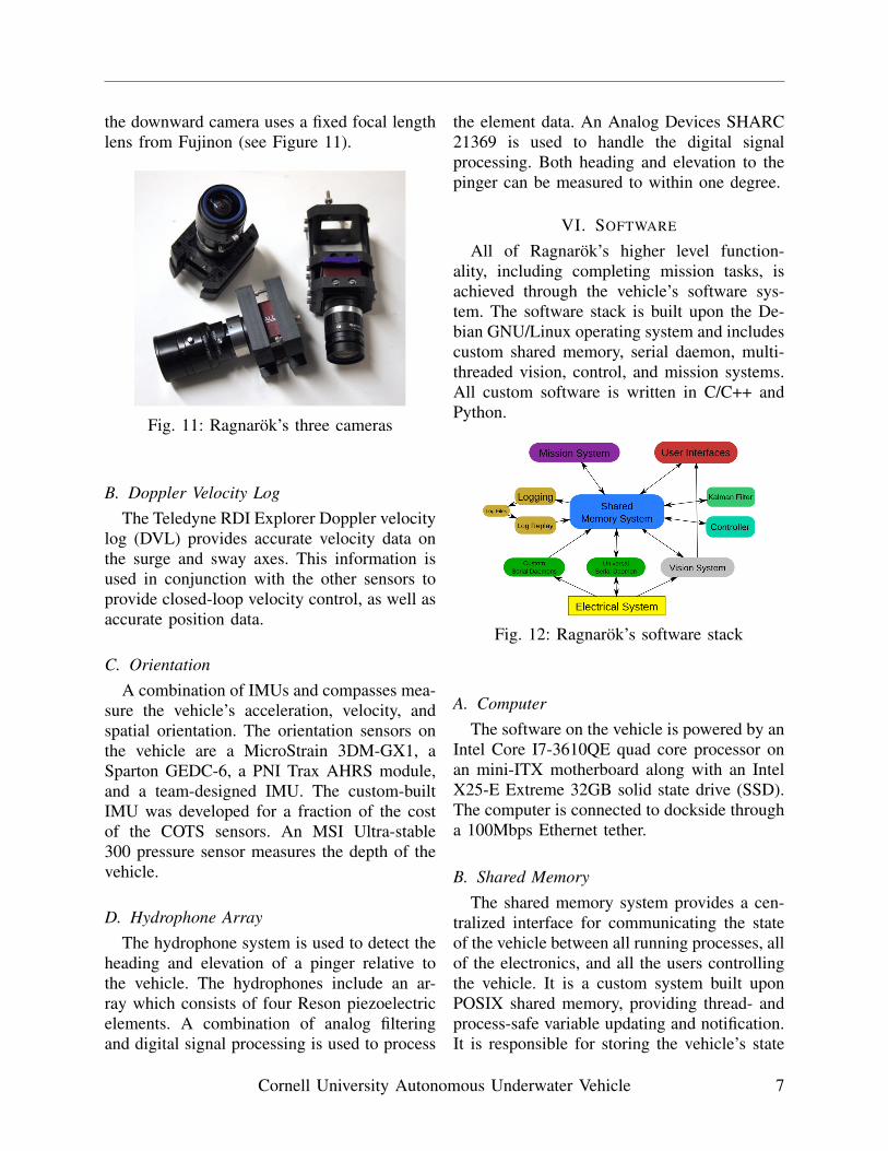
One new development in Ragnarok is theaddition of four bright LED strips controlledvia a new LED control board. (see Figure10). The LED control board takes input fromRagnarok’s software via serial and controls theLED strips, using them as visual indicators ofthe vehicle’s status. This is especially importantduring untethered runs, as the software teamcan monitor the mission progress at a glance.
Cornell University Autonomous Underwater Vehicle 5
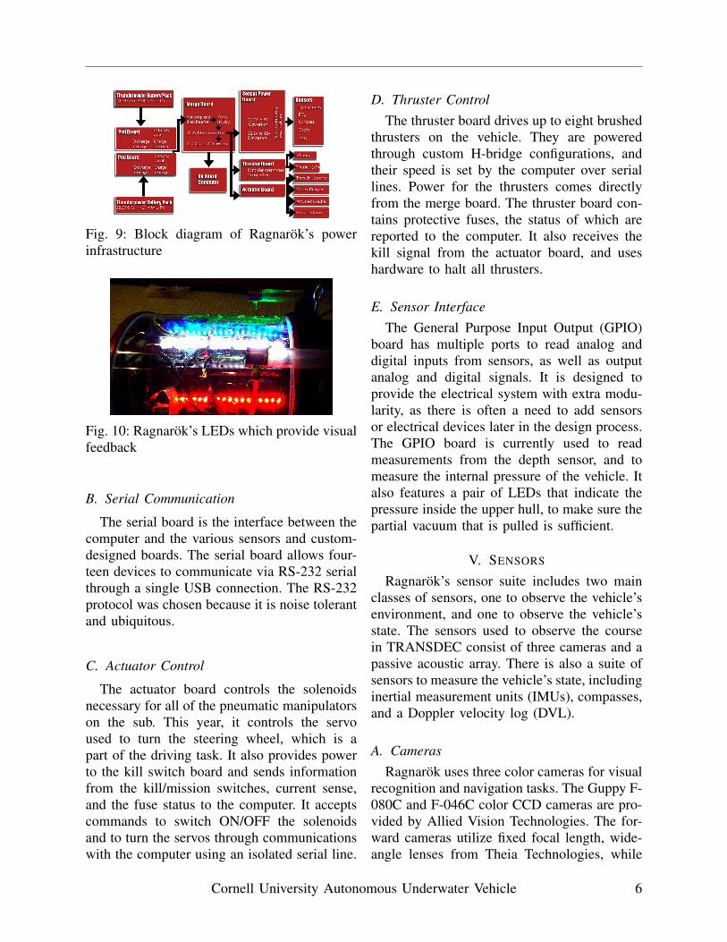
Fig. 9: Block diagram of Ragnarok’s powerinfrastructure
Fig. 10: Ragnarok’s LEDs which provide visualfeedback
B. Serial Communication
The serial board is the interface between thecomputer and the various sensors and custom-designed boards. The serial board allows four-teen devices to communicate via RS-232 serialthrough a single USB connection. The RS-232protocol was chosen because it is noise tolerantand ubiquitous.
C. Actuator Control
The actuator board controls the solenoidsnecessary for all of the pneumatic manipulatorson the sub. This year, it controls the servoused to turn the steering wheel, which is apart of the driving task. It also provides powerto the kill switch board and sends informationfrom the kill/mission switches, current sense,and the fuse status to the computer. It acceptscommands to switch ON/OFF the solenoidsand to turn the servos through communicationswith the computer using an isolated serial line.
D. Thruster ControlThe thruster board drives up to eight brushed
thrusters on the vehicle. They are poweredthrough custom H-bridge configurations, andtheir speed is set by the computer over seriallines. Power for the thrusters comes directlyfrom the merge board. The thruster board con-tains protective fuses, the status of which arereported to the computer. It also receives thekill signal from the actuator board, and useshardware to halt all thrusters.
E. Sensor InterfaceThe General Purpose Input Output (GPIO)
board has multiple ports to read analog anddigital inputs from sensors, as well as outputanalog and digital signals. It is designed toprovide the electrical system with extra modu-larity, as there is often a need to add sensorsor electrical devices later in the design process.The GPIO board is currently used to readmeasurements from the depth sensor, and tomeasure the internal pressure of the vehicle. Italso features a pair of LEDs that indicate thepressure inside the upper hull, to make sure thepartial vacuum that is pulled is sufficient.
V. SENSORS
Ragnarok’s sensor suite includes two mainclasses of sensors, one to observe the vehicle’senvironment, and one to observe the vehicle’sstate. The sensors used to observe the coursein TRANSDEC consist of three cameras and apassive acoustic array. There is also a suite ofsensors to measure the vehicle’s state, includinginertial measurement units (IMUs), compasses,and a Doppler velocity log (DVL).
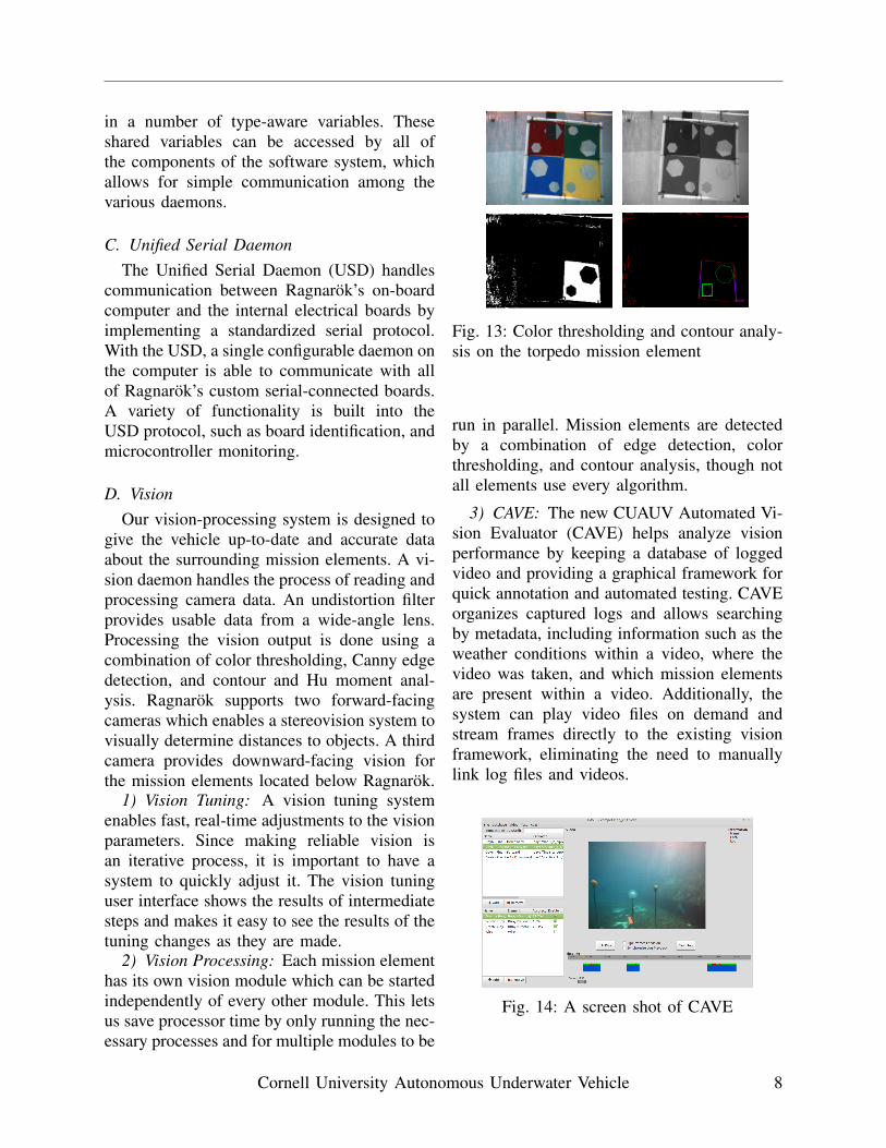
A. CamerasRagnarok uses three color cameras for visual
recognition and navigation tasks. The Guppy F-080C and F-046C color CCD cameras are pro-vided by Allied Vision Technologies. The for-ward cameras utilize fixed focal length, wide-angle lenses from Theia Technologies, while
Cornell University Autonomous Underwater Vehicle 6
the downward camera uses a fixed focal lengthlens from Fujinon (see Figure 11).
Fig. 11: Ragnarok’s three cameras
B. Doppler Velocity LogThe Teledyne RDI Explorer Doppler velocity
log (DVL) provides accurate velocity data onthe surge and sway axes. This information isused in conjunction with the other sensors toprovide closed-loop velocity control, as well asaccurate position data.
C. OrientationA combination of IMUs and compasses mea-
sure the vehicle’s acceleration, velocity, andspatial orientation. The orientation sensors onthe vehicle are a MicroStrain 3DM-GX1, aSparton GEDC-6, a PNI Trax AHRS module,and a team-designed IMU. The custom-builtIMU was developed for a fraction of the costof the COTS sensors. An MSI Ultra-stable300 pressure sensor measures the depth of thevehicle.
D. Hydrophone ArrayThe hydrophone system is used to detect the
heading and elevation of a pinger relative tothe vehicle. The hydrophones include an ar-ray which consists of four Reson piezoelectricelements. A combination of analog filteringand digital signal processing is used to process
the element data. An Analog Devices SHARC21369 is used to handle the digital signalprocessing. Both heading and elevation to thepinger can be measured to within one degree.
VI. SOFTWARE
All of Ragnarok’s higher level function-ality, including completing mission tasks, isachieved through the vehicle’s software sys-tem. The software stack is built upon the De-bian GNU/Linux operating system and includescustom shared memory, serial daemon, multi-threaded vision, control, and mission systems.All custom software is written in C/C++ andPython.
Fig. 12: Ragnarok’s software stack
A. ComputerThe software on the vehicle is powered by an
Intel Core I7-3610QE quad core processor onan mini-ITX motherboard along with an IntelX25-E Extreme 32GB solid state drive (SSD).The computer is connected to dockside througha 100Mbps Ethernet tether.
B. Shared MemoryThe shared memory system provides a cen-
tralized interface for communicating the stateof the vehicle between all running processes, allof the electronics, and all the users controllingthe vehicle. It is a custom system built uponPOSIX shared memory, providing thread- andprocess-safe variable updating and notification.It is responsible for storing the vehicle’s state
Cornell University Autonomous Underwater Vehicle 7
in a number of type-aware variables. Theseshared variables can be accessed by all ofthe components of the software system, whichallows for simple communication among thevarious daemons.
C. Unified Serial DaemonThe Unified Serial Daemon (USD) handles
communication between Ragnarok’s on-boardcomputer and the internal electrical boards byimplementing a standardized serial protocol.With the USD, a single configurable daemon onthe computer is able to communicate with allof Ragnarok’s custom serial-connected boards.A variety of functionality is built into theUSD protocol, such as board identification, andmicrocontroller monitoring.
D. VisionOur vision-processing system is designed to
give the vehicle up-to-date and accurate dataabout the surrounding mission elements. A vi-sion daemon handles the process of reading andprocessing camera data. An undistortion filterprovides usable data from a wide-angle lens.Processing the vision output is done using acombination of color thresholding, Canny edgedetection, and contour and Hu moment anal-ysis. Ragnarok supports two forward-facingcameras which enables a stereovision system tovisually determine distances to objects. A thirdcamera provides downward-facing vision forthe mission elements located below Ragnarok.
1) Vision Tuning: A vision tuning systemenables fast, real-time adjustments to the visionparameters. Since making reliable vision isan iterative process, it is important to have asystem to quickly adjust it. The vision tuninguser interface shows the results of intermediatesteps and makes it easy to see the results of thetuning changes as they are made.
2) Vision Processing: Each mission elementhas its own vision module which can be startedindependently of every other module. This letsus save processor time by only running the nec-essary processes and for multiple modules to be
Fig. 13: Color thresholding and contour analy-sis on the torpedo mission element
run in parallel. Mission elements are detectedby a combination of edge detection, colorthresholding, and contour analysis, though notall elements use every algorithm.
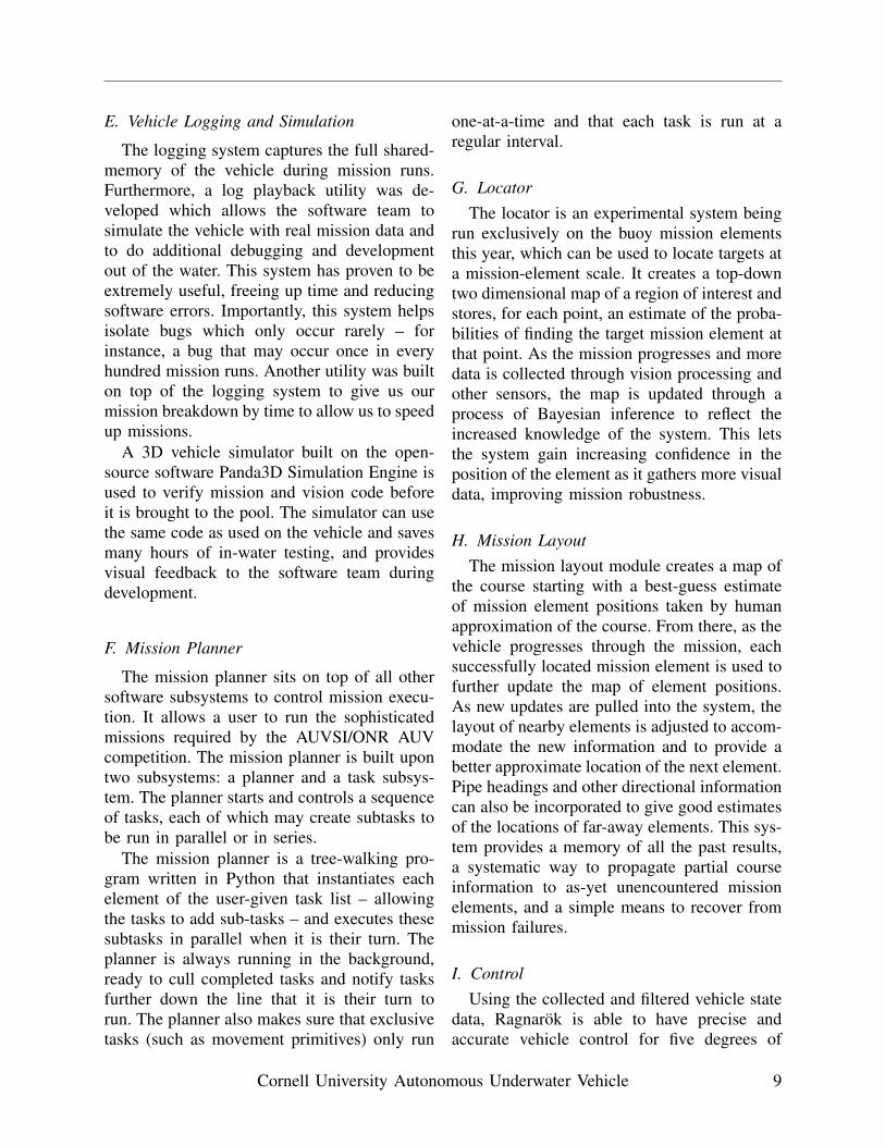
3) CAVE: The new CUAUV Automated Vi-sion Evaluator (CAVE) helps analyze visionperformance by keeping a database of loggedvideo and providing a graphical framework forquick annotation and automated testing. CAVEorganizes captured logs and allows searchingby metadata, including information such as theweather conditions within a video, where thevideo was taken, and which mission elementsare present within a video. Additionally, thesystem can play video files on demand andstream frames directly to the existing visionframework, eliminating the need to manuallylink log files and videos.
Fig. 14: A screen shot of CAVE
Cornell University Autonomous Underwater Vehicle 8
E. Vehicle Logging and Simulation
The logging system captures the full shared-memory of the vehicle during mission runs.Furthermore, a log playback utility was de-veloped which allows the software team tosimulate the vehicle with real mission data andto do additional debugging and developmentout of the water. This system has proven to beextremely useful, freeing up time and reducingsoftware errors. Importantly, this system helpsisolate bugs which only occur rarely – forinstance, a bug that may occur once in everyhundred mission runs. Another utility was builton top of the logging system to give us ourmission breakdown by time to allow us to speedup missions.
A 3D vehicle simulator built on the open-source software Panda3D Simulation Engine isused to verify mission and vision code beforeit is brought to the pool. The simulator can usethe same code as used on the vehicle and savesmany hours of in-water testing, and providesvisual feedback to the software team duringdevelopment.
F. Mission Planner
The mission planner sits on top of all othersoftware subsystems to control mission execu-tion. It allows a user to run the sophisticatedmissions required by the AUVSI/ONR AUVcompetition. The mission planner is built upontwo subsystems: a planner and a task subsys-tem. The planner starts and controls a sequenceof tasks, each of which may create subtasks tobe run in parallel or in series.
The mission planner is a tree-walking pro-gram written in Python that instantiates eachelement of the user-given task list – allowingthe tasks to add sub-tasks – and executes thesesubtasks in parallel when it is their turn. Theplanner is always running in the background,ready to cull completed tasks and notify tasksfurther down the line that it is their turn torun. The planner also makes sure that exclusivetasks (such as movement primitives) only run
one-at-a-time and that each task is run at aregular interval.
G. LocatorThe locator is an experimental system being
run exclusively on the buoy mission elementsthis year, which can be used to locate targets ata mission-element scale. It creates a top-downtwo dimensional map of a region of interest andstores, for each point, an estimate of the proba-bilities of finding the target mission element atthat point. As the mission progresses and moredata is collected through vision processing andother sensors, the map is updated through aprocess of Bayesian inference to reflect theincreased knowledge of the system. This letsthe system gain increasing confidence in theposition of the element as it gathers more visualdata, improving mission robustness.
H. Mission LayoutThe mission layout module creates a map of
the course starting with a best-guess estimateof mission element positions taken by humanapproximation of the course. From there, as thevehicle progresses through the mission, eachsuccessfully located mission element is used tofurther update the map of element positions.As new updates are pulled into the system, thelayout of nearby elements is adjusted to accom-modate the new information and to provide abetter approximate location of the next element.Pipe headings and other directional informationcan also be incorporated to give good estimatesof the locations of far-away elements. This sys-tem provides a memory of all the past results,a systematic way to propagate partial courseinformation to as-yet unencountered missionelements, and a simple means to recover frommission failures.
I. ControlUsing the collected and filtered vehicle state
data, Ragnarok is able to have precise andaccurate vehicle control for five degrees of
Cornell University Autonomous Underwater Vehicle 9
freedom: surge, sway, heave, yaw and pitch.The vehicle use a hand-tuned PID controllerfor each degree of freedom. The control systemmakes it easy for higher-level code, such asmission, to control the vehicle simply by settingdesired values for the velocity, depth, heading,and pitch.
For testing and research use, there are alsohave human-drivable controls using the con-trol helm tool. Control helm provides simplekeyboard controls. It also provides easy accessto control tuning (when in ‘expert mode’).Additionally, a new input method this yearallows the use of a 3dconnexion SpaceMousePro, a 3D mouse allowing easy control of thevehicle along all of its degrees of freedom.
VII. VEHICLE STATUS AND TESTING
Ragnarok is now in the testing phase. Priorto vehicle assembly, the mechanical systemswere thoroughly leak tested, and the electricalsystems were bench tested. The first in-watertest took place on April 21st. Ragnarok hadits first autonomous full-mission run in TeagleHall on June 28th, and testing has continuedsince.
Fig. 15: Ragnarok in the water at a pool test.
ACKNOWLEDGMENT
CUAUV would like to thank all the indi-viduals who have supported us over the pastyear, including Cornell’s MAE, ECE, ORIE,and CS departments, and Cornell Alumni whohave supplied our team with needed lab space,materials, tools, and funding. CUAUV wouldespecially like to our advisers, Professors Alan
Zehnder, Bruce Land, Graeme Bailey, and PeterJackson; Director of Cornell Aquatics FredDebruyn, the MAE Director of InstructionalLaboratories Matt Ulinski; and Cornell Engi-neering’s administrative staff, especially EmilyTompkins, Carol Moss, and Maureen Letteer.
We would also like to thank all of ourcorporate sponsors, without whom we wouldnot be able to compete:
Alumni Sponsors: Jim Clark; Erin Fischell;Sam Fladung; Kenneth Bongot; David Hayes;John Diamond; and Greg Meess.
Platinum Sponsors: Cornell University; Gen-eral Motors Foundation; NexLogic; MonsterTool Company; SEACON; VideoRay; andTeledyne RD Instruments.
Gold Sponsors: Theia Technologies; Math-Works; Portwell; General Electric; Allied Vi-sion Technologies; MicroStrain; SolidWorks;Intel; Shell; ConocoPhillips; and Seaperch.
Silver Sponsors: Patriot Memory; Pelican;SeaBotix; SGS Tool Company; Image LabsInternational; Prizm; PNI Sensor Corporation;Polymer Plastics Corporation (PPC); MaxonMotor; Bittele Electronics Inc.; and Sparton.
Bronze Sponsors: Sensata Technologies;Molex; The Mines Press Inc.; 3D Connexion;Thunder Power RC; Digi-Key; Polyform; Ed-mund Optics; APC International Ltd.; JetVend;Deep Sea Power & Light; Cayuga Xpress;Ocean Server Technology; Advanced Circuits;Asian Circuits; Surface Finish Technologies.
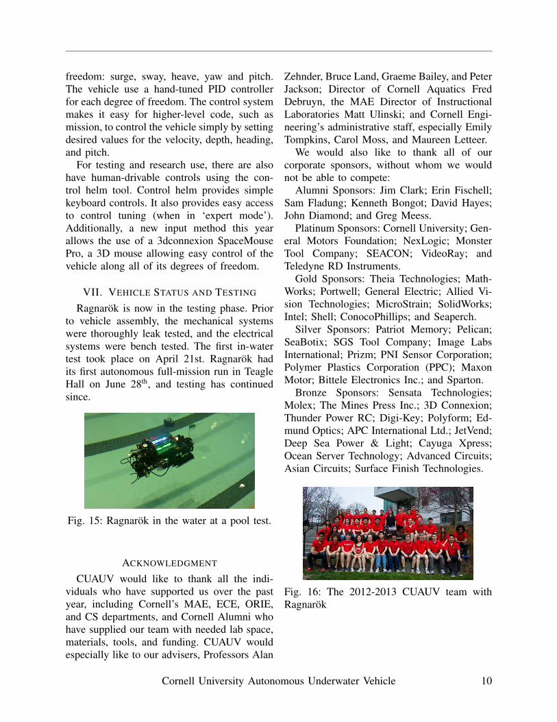
Fig. 16: The 2012-2013 CUAUV team withRagnarok
Cornell University Autonomous Underwater Vehicle 10