Coring Methods and Systems978-3-319-77733... · 2018-06-22 · Acknowledgements As Coring Methods...
22
Coring Methods and Systems
Transcript of Coring Methods and Systems978-3-319-77733... · 2018-06-22 · Acknowledgements As Coring Methods...

Coring Methods and Systems

Rahman Ashena • Gerhard Thonhauser
Coring Methods and Systems
123

Rahman AshenaDepartment of Petroleum EngineeringMontanuniversität LeobenLeobenAustria
Gerhard ThonhauserDepartment of Petroleum EngineeringMontanuniversität LeobenLeobenAustria
ISBN 978-3-319-77732-0 ISBN 978-3-319-77733-7 (eBook)https://doi.org/10.1007/978-3-319-77733-7
Library of Congress Control Number: 2018934944
© Springer International Publishing AG, part of Springer Nature 2018This work is subject to copyright. All rights are reserved by the Publisher, whether the whole or partof the material is concerned, specifically the rights of translation, reprinting, reuse of illustrations,recitation, broadcasting, reproduction on microfilms or in any other physical way, and transmissionor information storage and retrieval, electronic adaptation, computer software, or by similar or dissimilarmethodology now known or hereafter developed.The use of general descriptive names, registered names, trademarks, service marks, etc. in thispublication does not imply, even in the absence of a specific statement, that such names are exempt fromthe relevant protective laws and regulations and therefore free for general use.The publisher, the authors and the editors are safe to assume that the advice and information in thisbook are believed to be true and accurate at the date of publication. Neither the publisher nor theauthors or the editors give a warranty, express or implied, with respect to the material contained herein orfor any errors or omissions that may have been made. The publisher remains neutral with regard tojurisdictional claims in published maps and institutional affiliations.
Printed on acid-free paper
This Springer imprint is published by the registered company Springer International Publishing AGpart of Springer NatureThe registered company address is: Gewerbestrasse 11, 6330 Cham, Switzerland

Acknowledgements
As Coring Methods and Systems has greatly benefited from technical consultationcontributions of several individuals, we would like to express special words ofappreciation to Mr. George Williamson and Mr. Audun Kvinnesland, from BakerHughes GE; Mr. Ian Ross (for his continuous sincere support) and also Mr. CorinLewsey from National Oilwell Varco; Mr. Rudolf Nikolaus Knezevic from OMV;Mr. Jonathan Rylance and Mr. Alex Schellenberg from Reservoir Group; Mr. MikeBurns from Halliburton; Mr. Chris Daws and Mr. George Tophinke from Sandvik,Australia; Mr. Jos Nutbroek from Boart Longyear; Ms. Izaskun Zubizarreta fromLloyds Register; Mr. Tony Kennaird from Core Laboratories Australia; Mr. YuichiShinmoto from JAMSTEC; Prof. Walter Vortisch and Prof. Michael Prohaska fromMontanuniversität Leoben; and Dr. Christian Koller from TDE Group. We kindlyappreciate Mr. Ian Ross for his help on preparation of some of the schematics.Special thanks go to the companies which permitted us to use some of their figuresand tool specifications: Baker Hughes GE, National Oilwell Varco (NOV),Reservoir Group (formerly ALS Corpro), Halliburton, Sandvik, and BoartLongyear.
Finally, we appreciate Prof. Reza Rezaee from Curtin University for reviewingthe book and providing constructive comments.
Rahman AshenaGerhard Thonhauser
v

Contents
1 Introduction . . . . . . . . . . . . . . . . . . . . . . . . . . . . . . . . . . . . . . . . . . 11.1 General Introduction . . . . . . . . . . . . . . . . . . . . . . . . . . . . . . . . 11.2 Objectives . . . . . . . . . . . . . . . . . . . . . . . . . . . . . . . . . . . . . . . 21.3 Scope . . . . . . . . . . . . . . . . . . . . . . . . . . . . . . . . . . . . . . . . . . . 3
2 Justified Coring . . . . . . . . . . . . . . . . . . . . . . . . . . . . . . . . . . . . . . . . 72.1 Definition . . . . . . . . . . . . . . . . . . . . . . . . . . . . . . . . . . . . . . . . 72.2 Uncertainties and Challenges . . . . . . . . . . . . . . . . . . . . . . . . . . 8
2.2.1 Validity . . . . . . . . . . . . . . . . . . . . . . . . . . . . . . . . . . . 102.2.2 Cost . . . . . . . . . . . . . . . . . . . . . . . . . . . . . . . . . . . . . 10
2.3 Justification . . . . . . . . . . . . . . . . . . . . . . . . . . . . . . . . . . . . . . 112.3.1 Brief Comparison of Exploration Techniques . . . . . . . . 112.3.2 Justified Coring . . . . . . . . . . . . . . . . . . . . . . . . . . . . . 132.3.3 Example . . . . . . . . . . . . . . . . . . . . . . . . . . . . . . . . . . 15
References . . . . . . . . . . . . . . . . . . . . . . . . . . . . . . . . . . . . . . . . . . . . 16
3 Fundamental Coring Methods . . . . . . . . . . . . . . . . . . . . . . . . . . . . . 173.1 Introduction . . . . . . . . . . . . . . . . . . . . . . . . . . . . . . . . . . . . . . 173.2 Conventional Coring . . . . . . . . . . . . . . . . . . . . . . . . . . . . . . . . 173.3 Wireline Continuous Coring . . . . . . . . . . . . . . . . . . . . . . . . . . 193.4 Sidewall Coring . . . . . . . . . . . . . . . . . . . . . . . . . . . . . . . . . . . 21References . . . . . . . . . . . . . . . . . . . . . . . . . . . . . . . . . . . . . . . . . . . . 22
4 Types and Components of Core Barrel Assemblies . . . . . . . . . . . . . 234.1 Introduction . . . . . . . . . . . . . . . . . . . . . . . . . . . . . . . . . . . . . . 244.2 Core Barrel Types . . . . . . . . . . . . . . . . . . . . . . . . . . . . . . . . . . 244.3 Components of Core Barrel Assembly (Petroleum Industry) . . . 24
4.3.1 Conventional Core Barrel Assembly . . . . . . . . . . . . . . 244.3.2 Wireline Continuous Core Barrel Assembly . . . . . . . . . 31
4.4 Components of Core Barrel Assembly (Mining Industry) . . . . . 55References . . . . . . . . . . . . . . . . . . . . . . . . . . . . . . . . . . . . . . . . . . . . 68
vii

5 Conventional Coring . . . . . . . . . . . . . . . . . . . . . . . . . . . . . . . . . . . . 695.1 Introduction . . . . . . . . . . . . . . . . . . . . . . . . . . . . . . . . . . . . . . 695.2 Description . . . . . . . . . . . . . . . . . . . . . . . . . . . . . . . . . . . . . . . 695.3 Procedure . . . . . . . . . . . . . . . . . . . . . . . . . . . . . . . . . . . . . . . . 715.4 Challenges in Coring Operations . . . . . . . . . . . . . . . . . . . . . . . 78References . . . . . . . . . . . . . . . . . . . . . . . . . . . . . . . . . . . . . . . . . . . . 80
6 Wireline Continuous Coring . . . . . . . . . . . . . . . . . . . . . . . . . . . . . . 836.1 Introduction . . . . . . . . . . . . . . . . . . . . . . . . . . . . . . . . . . . . . . 836.2 Description . . . . . . . . . . . . . . . . . . . . . . . . . . . . . . . . . . . . . . . 856.3 Comparison with Other Methods . . . . . . . . . . . . . . . . . . . . . . . 89
6.3.1 Advantages . . . . . . . . . . . . . . . . . . . . . . . . . . . . . . . . 896.3.2 Disadvantages . . . . . . . . . . . . . . . . . . . . . . . . . . . . . . 94
6.4 Enclosed Ball and Seat . . . . . . . . . . . . . . . . . . . . . . . . . . . . . . 946.5 Latching Mechanism . . . . . . . . . . . . . . . . . . . . . . . . . . . . . . . . 95
6.5.1 Drilling Mode . . . . . . . . . . . . . . . . . . . . . . . . . . . . . . 956.5.2 Coring Mode . . . . . . . . . . . . . . . . . . . . . . . . . . . . . . . 96
6.6 Procedures . . . . . . . . . . . . . . . . . . . . . . . . . . . . . . . . . . . . . . . 966.6.1 Drilling Mode . . . . . . . . . . . . . . . . . . . . . . . . . . . . . . 966.6.2 Coring Mode . . . . . . . . . . . . . . . . . . . . . . . . . . . . . . . 98
6.7 Navigated Wireline Coring . . . . . . . . . . . . . . . . . . . . . . . . . . . 101References . . . . . . . . . . . . . . . . . . . . . . . . . . . . . . . . . . . . . . . . . . . . 102
7 Invasion–Mitigation Coring . . . . . . . . . . . . . . . . . . . . . . . . . . . . . . 1057.1 Introduction . . . . . . . . . . . . . . . . . . . . . . . . . . . . . . . . . . . . . . 1057.2 Invasion Areas and Factors . . . . . . . . . . . . . . . . . . . . . . . . . . . 1067.3 Low-Invasion Coring System. . . . . . . . . . . . . . . . . . . . . . . . . . 109
7.3.1 Optimized Core Bits . . . . . . . . . . . . . . . . . . . . . . . . . . 1107.3.2 Optimized Mud Properties . . . . . . . . . . . . . . . . . . . . . 1147.3.3 High ROP Relative to Invasion . . . . . . . . . . . . . . . . . . 115
7.4 Gel Coring System . . . . . . . . . . . . . . . . . . . . . . . . . . . . . . . . . 1157.4.1 Description . . . . . . . . . . . . . . . . . . . . . . . . . . . . . . . . 1167.4.2 Closed Inner Tube . . . . . . . . . . . . . . . . . . . . . . . . . . . 118
7.5 Sponge Coring . . . . . . . . . . . . . . . . . . . . . . . . . . . . . . . . . . . . 1187.5.1 Description . . . . . . . . . . . . . . . . . . . . . . . . . . . . . . . . 1187.5.2 Challenges . . . . . . . . . . . . . . . . . . . . . . . . . . . . . . . . . 121
References . . . . . . . . . . . . . . . . . . . . . . . . . . . . . . . . . . . . . . . . . . . . 121
8 Mechanical Core Damage Investigation and Mitigation . . . . . . . . . 1238.1 Introduction . . . . . . . . . . . . . . . . . . . . . . . . . . . . . . . . . . . . . . 1238.2 During Core-Drilling . . . . . . . . . . . . . . . . . . . . . . . . . . . . . . . . 123
8.2.1 Induced Fractures . . . . . . . . . . . . . . . . . . . . . . . . . . . . 1248.2.2 Vibration . . . . . . . . . . . . . . . . . . . . . . . . . . . . . . . . . . 125
viii Contents

8.3 During Tripping . . . . . . . . . . . . . . . . . . . . . . . . . . . . . . . . . . . 1258.3.1 Tripping Rate . . . . . . . . . . . . . . . . . . . . . . . . . . . . . . . 1268.3.2 Core Barrel Length . . . . . . . . . . . . . . . . . . . . . . . . . . . 1308.3.3 Operational Measures . . . . . . . . . . . . . . . . . . . . . . . . . 132
References . . . . . . . . . . . . . . . . . . . . . . . . . . . . . . . . . . . . . . . . . . . . 132
9 Jam Mitigation Coring . . . . . . . . . . . . . . . . . . . . . . . . . . . . . . . . . . 1359.1 Introduction . . . . . . . . . . . . . . . . . . . . . . . . . . . . . . . . . . . . . . 1359.2 Operational Parameters and Jam Detection . . . . . . . . . . . . . . . . 136
9.2.1 Rate of Penetration . . . . . . . . . . . . . . . . . . . . . . . . . . . 1369.2.2 Standpipe Pressure . . . . . . . . . . . . . . . . . . . . . . . . . . . 1369.2.3 Mud Circulation Rate . . . . . . . . . . . . . . . . . . . . . . . . . 1399.2.4 Weight on Bit . . . . . . . . . . . . . . . . . . . . . . . . . . . . . . 1409.2.5 Rotary Speed . . . . . . . . . . . . . . . . . . . . . . . . . . . . . . . 1409.2.6 Torque . . . . . . . . . . . . . . . . . . . . . . . . . . . . . . . . . . . . 1419.2.7 Observations . . . . . . . . . . . . . . . . . . . . . . . . . . . . . . . 141
9.3 Antijamming Coring . . . . . . . . . . . . . . . . . . . . . . . . . . . . . . . . 1419.4 Full-Closure Coring . . . . . . . . . . . . . . . . . . . . . . . . . . . . . . . . 145References . . . . . . . . . . . . . . . . . . . . . . . . . . . . . . . . . . . . . . . . . . . . 147
10 Oriented Coring . . . . . . . . . . . . . . . . . . . . . . . . . . . . . . . . . . . . . . . 14910.1 Introduction . . . . . . . . . . . . . . . . . . . . . . . . . . . . . . . . . . . . . . 14910.2 Description . . . . . . . . . . . . . . . . . . . . . . . . . . . . . . . . . . . . . . . 14910.3 Tool Arrangement and Components . . . . . . . . . . . . . . . . . . . . . 15010.4 Types of Survey Tools . . . . . . . . . . . . . . . . . . . . . . . . . . . . . . 157References . . . . . . . . . . . . . . . . . . . . . . . . . . . . . . . . . . . . . . . . . . . . 160
11 Pressure/In Situ Coring . . . . . . . . . . . . . . . . . . . . . . . . . . . . . . . . . . 16111.1 Introduction . . . . . . . . . . . . . . . . . . . . . . . . . . . . . . . . . . . . . . 16111.2 Original-Pressure Coring . . . . . . . . . . . . . . . . . . . . . . . . . . . . . 16211.3 Pseudo-Pressure Coring . . . . . . . . . . . . . . . . . . . . . . . . . . . . . . 16211.4 Advantages and Disadvantages . . . . . . . . . . . . . . . . . . . . . . . . 16411.5 Operating Procedure . . . . . . . . . . . . . . . . . . . . . . . . . . . . . . . . 168References . . . . . . . . . . . . . . . . . . . . . . . . . . . . . . . . . . . . . . . . . . . . 169
12 Logging-While-Coring . . . . . . . . . . . . . . . . . . . . . . . . . . . . . . . . . . . 17112.1 Introduction . . . . . . . . . . . . . . . . . . . . . . . . . . . . . . . . . . . . . . 17112.2 Methods of Downhole Logging . . . . . . . . . . . . . . . . . . . . . . . . 17312.3 LWC Systems . . . . . . . . . . . . . . . . . . . . . . . . . . . . . . . . . . . . 17612.4 RAB System . . . . . . . . . . . . . . . . . . . . . . . . . . . . . . . . . . . . . 177
12.4.1 DSS-RMM System . . . . . . . . . . . . . . . . . . . . . . . . . . . 18112.5 Data Telemetry . . . . . . . . . . . . . . . . . . . . . . . . . . . . . . . . . . . . 182References . . . . . . . . . . . . . . . . . . . . . . . . . . . . . . . . . . . . . . . . . . . . 188
Contents ix

13 Other Coring Systems . . . . . . . . . . . . . . . . . . . . . . . . . . . . . . . . . . . 18913.1 Introduction . . . . . . . . . . . . . . . . . . . . . . . . . . . . . . . . . . . . . . 18913.2 Motor Coring . . . . . . . . . . . . . . . . . . . . . . . . . . . . . . . . . . . . . 18913.3 Mini-Coring . . . . . . . . . . . . . . . . . . . . . . . . . . . . . . . . . . . . . . 19213.4 Coiled-Tubing Coring . . . . . . . . . . . . . . . . . . . . . . . . . . . . . . . 19413.5 Underbalanced Coring . . . . . . . . . . . . . . . . . . . . . . . . . . . . . . . 195References . . . . . . . . . . . . . . . . . . . . . . . . . . . . . . . . . . . . . . . . . . . . 196
14 Core Handling . . . . . . . . . . . . . . . . . . . . . . . . . . . . . . . . . . . . . . . . 19714.1 Introduction . . . . . . . . . . . . . . . . . . . . . . . . . . . . . . . . . . . . . . 19714.2 Handling Tools . . . . . . . . . . . . . . . . . . . . . . . . . . . . . . . . . . . . 19814.3 Procedure . . . . . . . . . . . . . . . . . . . . . . . . . . . . . . . . . . . . . . . . 19914.4 Recommendations . . . . . . . . . . . . . . . . . . . . . . . . . . . . . . . . . . 210References . . . . . . . . . . . . . . . . . . . . . . . . . . . . . . . . . . . . . . . . . . . . 211
15 Coring Providers and Patents . . . . . . . . . . . . . . . . . . . . . . . . . . . . . 21315.1 Introduction . . . . . . . . . . . . . . . . . . . . . . . . . . . . . . . . . . . . . . 21315.2 Coring Providers and Specifications . . . . . . . . . . . . . . . . . . . . . 213
15.2.1 Petroleum Sector . . . . . . . . . . . . . . . . . . . . . . . . . . . . 21415.2.2 Mining Sector . . . . . . . . . . . . . . . . . . . . . . . . . . . . . . 225
15.3 Coring-Related Patents . . . . . . . . . . . . . . . . . . . . . . . . . . . . . . 225
Appendix . . . . . . . . . . . . . . . . . . . . . . . . . . . . . . . . . . . . . . . . . . . . . . . . . . . 241
x Contents
List of Figures
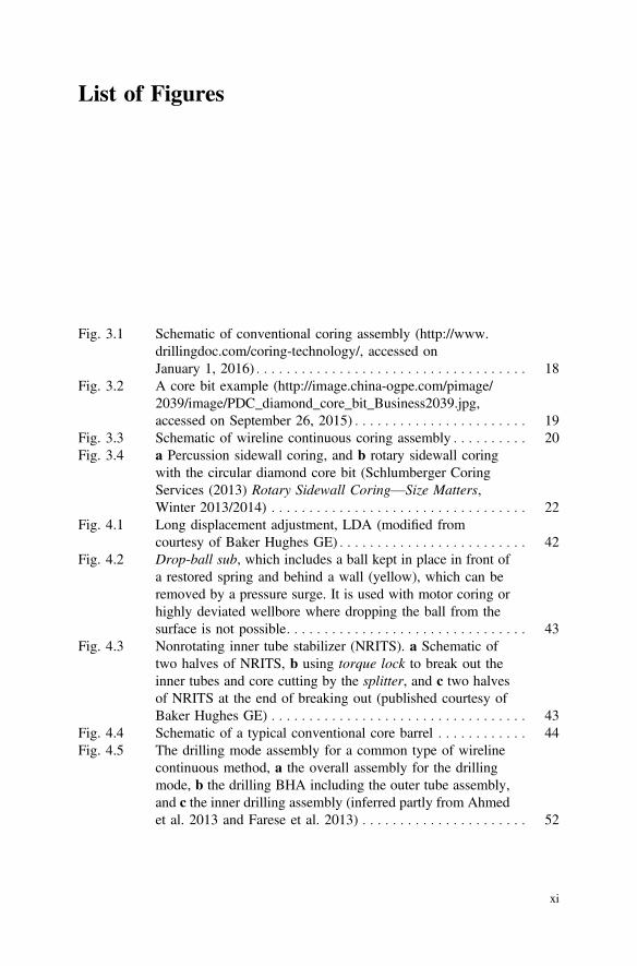
Fig. 3.1 Schematic of conventional coring assembly (http://www.drillingdoc.com/coring-technology/, accessed onJanuary 1, 2016) . . . . . . . . . . . . . . . . . . . . . . . . . . . . . . . . . . . . 18
Fig. 3.2 A core bit example (http://image.china-ogpe.com/pimage/2039/image/PDC_diamond_core_bit_Business2039.jpg,accessed on September 26, 2015) . . . . . . . . . . . . . . . . . . . . . . . 19
Fig. 3.3 Schematic of wireline continuous coring assembly . . . . . . . . . . 20Fig. 3.4 a Percussion sidewall coring, and b rotary sidewall coring
with the circular diamond core bit (Schlumberger CoringServices (2013) Rotary Sidewall Coring—Size Matters,Winter 2013/2014) . . . . . . . . . . . . . . . . . . . . . . . . . . . . . . . . . . 22
Fig. 4.1 Long displacement adjustment, LDA (modified fromcourtesy of Baker Hughes GE) . . . . . . . . . . . . . . . . . . . . . . . . . 42
Fig. 4.2 Drop-ball sub, which includes a ball kept in place in front ofa restored spring and behind a wall (yellow), which can beremoved by a pressure surge. It is used with motor coring orhighly deviated wellbore where dropping the ball from thesurface is not possible. . . . . . . . . . . . . . . . . . . . . . . . . . . . . . . . 43
Fig. 4.3 Nonrotating inner tube stabilizer (NRITS). a Schematic oftwo halves of NRITS, b using torque lock to break out theinner tubes and core cutting by the splitter, and c two halvesof NRITS at the end of breaking out (published courtesy ofBaker Hughes GE) . . . . . . . . . . . . . . . . . . . . . . . . . . . . . . . . . . 43
Fig. 4.4 Schematic of a typical conventional core barrel . . . . . . . . . . . . 44Fig. 4.5 The drilling mode assembly for a common type of wireline
continuous method, a the overall assembly for the drillingmode, b the drilling BHA including the outer tube assembly,and c the inner drilling assembly (inferred partly from Ahmedet al. 2013 and Farese et al. 2013) . . . . . . . . . . . . . . . . . . . . . . 52
xi

Fig. 4.6 The coring mode assembly for a common type of wirelinecontinuous method, a the overall coring assembly includingthe outer tube assembly, and b the inner tube assembly(inferred partly from Ahmed et al. 2013 andFarese et al. 2013) . . . . . . . . . . . . . . . . . . . . . . . . . . . . . . . . . . 53
Fig. 4.7 The schematic for another type of continuous wirelinemethod: a the outer tube assembly, and b the inner drillingassembly (drilling mode) . . . . . . . . . . . . . . . . . . . . . . . . . . . . . 54
Fig. 4.8 Schematics of a API drill pipes: (1) components including thetool joints, (2) with internal upset, IU, external upset, EU, andinternal-external upset, IEU (Mitchell and Miska 2011), andb half-section of typical mining drill rods (which has onlyminimal internal-upsets) . . . . . . . . . . . . . . . . . . . . . . . . . . . . . . 55
Fig. 4.9 The whole mining core barrel components. a The outer tubeassembly, and b the inner tube assembly comprising theupper inner tube assembly (the upper head assembly andlower head assembly), and the lower inner tube assembly(from top to bottom) . . . . . . . . . . . . . . . . . . . . . . . . . . . . . . . . . 63
Fig. 4.10 Schematics of a the core barrel assembly (with the inner tubeon the left, and the outer tube on the right), and b the headassembly (courtesy of Sandvik 2013) . . . . . . . . . . . . . . . . . . . . 66
Fig. 4.11 The schematic of surface-underground coring components:a the core barrel assembly with the inner tube (left) and theouter tube (right), and b the head assembly. Depending on thetype of the drill rods, the core barrel can be HSU, NSU, etc.[courtesy of Sandvik (2013), Sandvik HSU, a modern corebarrel recently developed which is appropriate for bothunderground and surface coring operations (SU)] . . . . . . . . . . . 67
Fig. 5.1 Conventional coring prior to coring start ordrop of the ball . . . . . . . . . . . . . . . . . . . . . . . . . . . . . . . . . . . . . 72
Fig. 5.2 Conventional coring after the ball was dropped (duringcoring), illustrating conventional core barrel and mudcirculation path shown by red arrows . . . . . . . . . . . . . . . . . . . . 73
Fig. 5.3 The BHA assembly in conventional coring (using thetop-drive system). The connection joints of the outer and theinner tubes have been already made on the ground for quickeroperations (published courtesy of Baker Hughes GE) . . . . . . . . 74
Fig. 5.4 A bit blade as the junk riding on top of the core sample(photo published courtesy of Baker Hughes GE) . . . . . . . . . . . 80
Fig. 6.1 Drilling mode with the inner drilling assembly inside theouter tube assembly on the top and bottom, respectively,by mechanical and hydraulic latching assemblies, a prior tolatching and drilling, b after latching and while drilling . . . . . . 86
xii List of Figures

Fig. 6.2 Another type of inner drilling assembly in which the innerassembly is near its bottom at the drive latch assembly . . . . . . 87
Fig. 6.3 Coring mode with the inner tube assembly inside the outertube assembly a during coring/core-drilling, b just at the endof coring when the inner tube becomes full or core jammingoccurs (which is signed by the lifting of the pressure head, thered circle) . . . . . . . . . . . . . . . . . . . . . . . . . . . . . . . . . . . . . . . . . 88
Fig. 6.4 Application of wheeled cart to the bottom of an inner drillingassembly for protection of the drill insert while raising it fromthe catwalk (through the V-door) to the rig floor . . . . . . . . . . . 97
Fig. 6.5 Navigated wireline continuous coring with gamma-ray anddirectional survey in the drilling mode (published courtesy ofBaker Hughes GE) . . . . . . . . . . . . . . . . . . . . . . . . . . . . . . . . . . 101
Fig. 7.1 The outer and the central parts of a typical 4-in. core obtainedby conventional tools. For example, the central partwith 2½-in. for a 4-in. core may be uninvaded. . . . . . . . . . . . . 106
Fig. 7.2 The three principal areas where mud invasion occurs duringcoring, consisting of: (1) ahead the bit, (2) at the bit face andthroat, (3) in the inner tube, shown in two views . . . . . . . . . . . 107
Fig. 7.3 The schematic of less-invaded core plug taken from a typicallow-invasion coring system, which provides a centraluninvaded portion for core analysis. This is useful forRoutine Core Analysis, RCAL and Special Core Analysis,SCAL . . . . . . . . . . . . . . . . . . . . . . . . . . . . . . . . . . . . . . . . . . . . 109
Fig. 7.4 a Conventional lower shoe and b extended lower shoe forlow-invasion coring (published courtesyof Baker Hughes GE) . . . . . . . . . . . . . . . . . . . . . . . . . . . . . . . . 110
Fig. 7.5 A schematic of a low-invasion core bit and the pilot/lowershoe to show the minimal difference between the InsideDiameter (ID) of the bit and the Outside Diameter(OD) of the inner shoe (i.e., the lowest clearance for the mudto pass from the bit throat to the bit) (published courtesyof Baker Hughes GE) . . . . . . . . . . . . . . . . . . . . . . . . . . . . . . . . 111
Fig. 7.6 Schematics comparing: a a typical conventional core bit andb a low-invasion core bit . . . . . . . . . . . . . . . . . . . . . . . . . . . . . 112
Fig. 7.7 a Conventional lower/pilot shoe, and b extended/low-invasion lower shoe (published courtesyof Baker Hughes GE) . . . . . . . . . . . . . . . . . . . . . . . . . . . . . . . . 113
Fig. 7.8 The depth of invasion of the drilling mud in the cut coresample (plan view) a in macroscopic plan view and b themicroscopic plan view . . . . . . . . . . . . . . . . . . . . . . . . . . . . . . . 114
List of Figures xiii

Fig. 7.9 Drilling mud invasion using three coring systems usinga standard core head/bit, b low-invasion coring, and c gelcoring with the low-invasion system. . . . . . . . . . . . . . . . . . . . . 116
Fig. 7.10 The working mechanism of the gel coring system. a Theinner tube floating piston or gel rabbit is closed before coringcommences, b Gel release valve opens after being touched bythe core and c Gel encapsulates and preserves the core.(Modified from Skopec and Mcleod 1997) . . . . . . . . . . . . . . . . 117
Fig. 7.11 Aluminum inner tube including the sponge(Shale et al. 2014) . . . . . . . . . . . . . . . . . . . . . . . . . . . . . . . . . . 120
Fig. 7.12 a Protective nylon meshweb which protects the spongetexture and tightens the core to the sponge (Shale et al. 2014)and b the sponge liner (published courtesyof Baker Hughes GE) . . . . . . . . . . . . . . . . . . . . . . . . . . . . . . . . 120
Fig. 7.13 Backside of the sponge aluminum liner including the flutesfor the gas and liquid flow (published courtesyof Baker Hughes GE) . . . . . . . . . . . . . . . . . . . . . . . . . . . . . . . . 120
Fig. 8.1 Contours of mean principal stress induced by theaxisymmetric model of a parabolic core bit (with WOB of 10tonne, vertical stress of 7400 psi, minimum and maximumhorizontal stresses of 6380 psi, MW of 13.34 ppg, at the TrueVertical Depth (TVD) of 2540 m). The rock material hasbeen assumed linear elastic. The curves with the values of0.5–2 show the stress ratios (Hettema et al. 2002) . . . . . . . . . . 124
Fig. 8.2 CT scan images showing microfractures in a core(Mcphee et al. 2015; Zubizarreta et al. 2013;Byrne et al. 2015). . . . . . . . . . . . . . . . . . . . . . . . . . . . . . . . . . . 126
Fig. 8.3 Maximum allowable tripping rate for gas, oil, andwater-bearing cores with different permeability and hydraulicdiffusivity values: a for 0.01–1 mD, b for 0.0001–0.001 mD(Ashena et al. 2018) . . . . . . . . . . . . . . . . . . . . . . . . . . . . . . . . . 129
Fig. 8.4 The induced radial stress, y-axis, versus the radial locationfrom the center, x-axis (0 � r/R � 1) using wireline trippingrate (Ashena 2017). The red line represents the tensilestrength of the core . . . . . . . . . . . . . . . . . . . . . . . . . . . . . . . . . . 130
Fig. 8.5 A typical core barrel length design versus DLS variations.The blue and red lines, respectively, correspond to 8½-in.and 6-in. hole sizes with the same outertube OD of 6¾-in. . . . . . . . . . . . . . . . . . . . . . . . . . . . . . . . . . . 131
Fig. 9.1 Using core jam indicator in conventional coring to enablequick detection of jamming. In case of jamming, when theinner tube is lifted, the jam-indicator sub is moved such that itcan make a restriction against the mud flow path through the
xiv List of Figures

annulus between the inner and outer tubes. This causes aninstant increase in the standpipe pressure . . . . . . . . . . . . . . . . . 137
Fig. 9.2 Core jamming indication in wireline continuous coring:a while core drilling is in progress (prior to core jamming),b when jamming occurs, the inner tube is lifted upimmediately (because it is hydraulic) which causes the mudflow to pass through the annulus between the inner and theouter tubes instead of through the flow cap assembly. Thiscauses an instant drop of the standpipe pressure. Compareit with jamming in conventional coring equipped with a jamindicator (Fig. 9.1) . . . . . . . . . . . . . . . . . . . . . . . . . . . . . . . . . . 138
Fig. 9.3 A schematic of antijamming telescoping inner barrel(published courtesy of Baker Hughes GE) . . . . . . . . . . . . . . . . 143
Fig. 9.4 The succession of jams in antijamming coring system (withmaximum three jams): a core enters the first sleeve until thefirst jam occurs and shears the pin, b freed inner sleevetelescopes up the core barrel and second sleeve receives newcore, c second jam occurs which shears the pins and releasesthe second telescoping sleeve. Coring continues until thethird jam occurs or the inner tube is full (Zahid et al. 2011;Gehad et al. 2014) . . . . . . . . . . . . . . . . . . . . . . . . . . . . . . . . . . 144
Fig. 9.5 a The slick wall of the inner tube, b a full-closure dualcatcher prior to activation, and c the full-closure dual catcherafter activation with the shells/halves in the closed state(published courtesy of Baker Hughes GE) . . . . . . . . . . . . . . . . 145
Fig. 9.6 Full-closure system (upper part): (1) before activation,(2) after activation, and (3) when complete closing andsealing has been achieved from the bottom(refer to Fig. 9.7) . . . . . . . . . . . . . . . . . . . . . . . . . . . . . . . . . . . 146
Fig. 9.7 Full-closure system (lower part): (1) during coring beforeactivation, and (2) after activation and just prior to pulling outof the hole . . . . . . . . . . . . . . . . . . . . . . . . . . . . . . . . . . . . . . . . 147
Fig. 10.1 Schematic of oriented coring (published courtesy of BakerHughes GE) . . . . . . . . . . . . . . . . . . . . . . . . . . . . . . . . . . . . . . . 151
Fig. 10.2 The arrangement of the oriented core barrel (modified fromFig. 1 of Hay et al. 1990) . . . . . . . . . . . . . . . . . . . . . . . . . . . . . 152
Fig. 10.3 A typical schematic of an oriented coring tool for wirelinecontinuous coring . . . . . . . . . . . . . . . . . . . . . . . . . . . . . . . . . . . 153
Fig. 10.4 The arrangement of a typical survey tool (inferred andmodified from Figs. 2 and 3 of Brindley and Sperry-Sun1988; Fig. 1 of Hay et al. 1990) . . . . . . . . . . . . . . . . . . . . . . . . 154
List of Figures xv
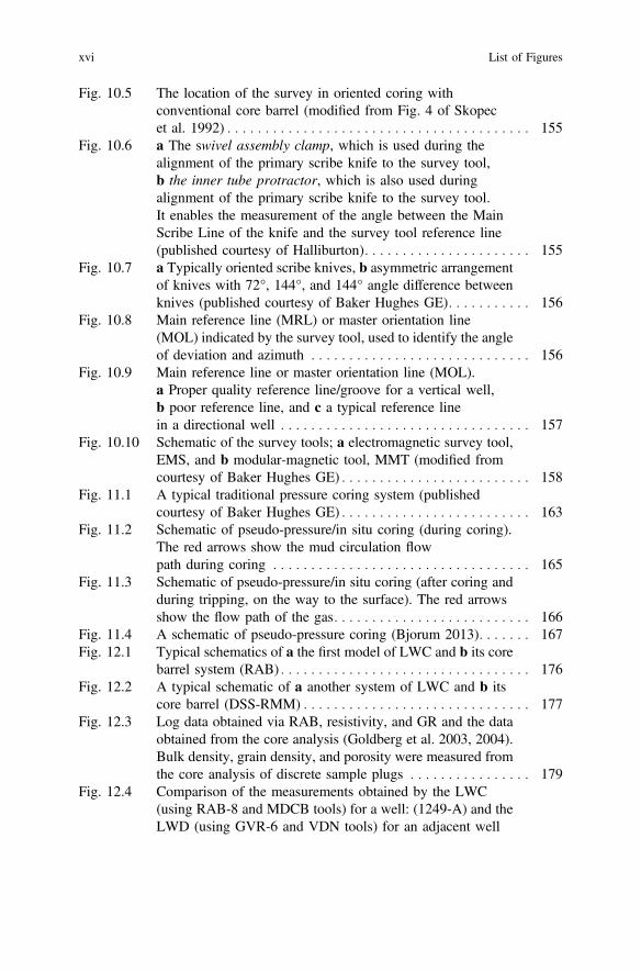
Fig. 10.5 The location of the survey in oriented coring withconventional core barrel (modified from Fig. 4 of Skopecet al. 1992) . . . . . . . . . . . . . . . . . . . . . . . . . . . . . . . . . . . . . . . . 155
Fig. 10.6 a The swivel assembly clamp, which is used during thealignment of the primary scribe knife to the survey tool,b the inner tube protractor, which is also used duringalignment of the primary scribe knife to the survey tool.It enables the measurement of the angle between the MainScribe Line of the knife and the survey tool reference line(published courtesy of Halliburton). . . . . . . . . . . . . . . . . . . . . . 155
Fig. 10.7 a Typically oriented scribe knives, b asymmetric arrangementof knives with 72°, 144°, and 144° angle difference betweenknives (published courtesy of Baker Hughes GE). . . . . . . . . . . 156
Fig. 10.8 Main reference line (MRL) or master orientation line(MOL) indicated by the survey tool, used to identify the angleof deviation and azimuth . . . . . . . . . . . . . . . . . . . . . . . . . . . . . 156
Fig. 10.9 Main reference line or master orientation line (MOL).a Proper quality reference line/groove for a vertical well,b poor reference line, and c a typical reference linein a directional well . . . . . . . . . . . . . . . . . . . . . . . . . . . . . . . . . 157
Fig. 10.10 Schematic of the survey tools; a electromagnetic survey tool,EMS, and b modular-magnetic tool, MMT (modified fromcourtesy of Baker Hughes GE) . . . . . . . . . . . . . . . . . . . . . . . . . 158
Fig. 11.1 A typical traditional pressure coring system (publishedcourtesy of Baker Hughes GE) . . . . . . . . . . . . . . . . . . . . . . . . . 163
Fig. 11.2 Schematic of pseudo-pressure/in situ coring (during coring).The red arrows show the mud circulation flowpath during coring . . . . . . . . . . . . . . . . . . . . . . . . . . . . . . . . . . 165
Fig. 11.3 Schematic of pseudo-pressure/in situ coring (after coring andduring tripping, on the way to the surface). The red arrowsshow the flow path of the gas. . . . . . . . . . . . . . . . . . . . . . . . . . 166
Fig. 11.4 A schematic of pseudo-pressure coring (Bjorum 2013). . . . . . . 167Fig. 12.1 Typical schematics of a the first model of LWC and b its core
barrel system (RAB) . . . . . . . . . . . . . . . . . . . . . . . . . . . . . . . . . 176Fig. 12.2 A typical schematic of a another system of LWC and b its
core barrel (DSS-RMM) . . . . . . . . . . . . . . . . . . . . . . . . . . . . . . 177Fig. 12.3 Log data obtained via RAB, resistivity, and GR and the data
obtained from the core analysis (Goldberg et al. 2003, 2004).Bulk density, grain density, and porosity were measured fromthe core analysis of discrete sample plugs . . . . . . . . . . . . . . . . 179
Fig. 12.4 Comparison of the measurements obtained by the LWC(using RAB-8 and MDCB tools) for a well: (1249-A) and theLWD (using GVR-6 and VDN tools) for an adjacent well
xvi List of Figures

(1249-B). The depths are in meters(Goldberg et al. 2003, 2004). . . . . . . . . . . . . . . . . . . . . . . . . . . 182
Fig. 12.5 Application of coils to transmit the data from DSS DC to theRMM core barrel (inductive data link system) (modified fromGoldberg et al. 2006) . . . . . . . . . . . . . . . . . . . . . . . . . . . . . . . . 183
Fig. 12.6 The dark blue color (representing the DSS measurement) andthe dark red (representing the data received in RMM) fall oneach other, which is indicative of proper data transmissionbetween the sensors (Myers et al. 2006;Goldberg et al. 2006) . . . . . . . . . . . . . . . . . . . . . . . . . . . . . . . . 185
Fig. 12.7 Logging-While-Coring (LWC) with real-time data telemetry.Compare with Fig. 12.2a . . . . . . . . . . . . . . . . . . . . . . . . . . . . . 187
Fig. 13.1 The schematic of a motor coring system. . . . . . . . . . . . . . . . . . 191Fig. 13.2 Schematic showing the micro-coring concept
(Shinmoto et al. 2012) . . . . . . . . . . . . . . . . . . . . . . . . . . . . . . . 192Fig. 13.3 An example of a 6-in micro-core bit
(Deschamps et al. 2008) . . . . . . . . . . . . . . . . . . . . . . . . . . . . . . 193Fig. 13.4 a Ductile cuttings, b micro-cores, and c brittle cuttings
(Deschamps et al. 2008) . . . . . . . . . . . . . . . . . . . . . . . . . . . . . . 194Fig. 13.5 Typical coiled-tubing rig for coring (published courtesy of
Baker Hughes GE) . . . . . . . . . . . . . . . . . . . . . . . . . . . . . . . . . . 195Fig. 14.1 Drop-ball pick-up tool to extract the ball stuck inside the
inner tube (published courtesy of Baker Hughes GE) . . . . . . . . 198Fig. 14.2 The inner tube lift bail, which is used for lifting the inner tube
out of the hole (published courtesy of Baker Hughes GE) . . . . 198Fig. 14.3 The bit breaker, used to remove the core bit (published
courtesy of Baker Hughes GE) . . . . . . . . . . . . . . . . . . . . . . . . . 199Fig. 14.4 Some standard core lay-down tools and methods (published
courtesy of Baker Hughes GE): a Four-point (spreader)beam-sling, which uses four ropes to attach, lift, and transferthe inner tube from lay-down-frame (LDF) to the pipe deck.b The inner tube is fastened to the clamp from the bottom andattached to a cradle using two ropes near the top and bottomof the barrel. c A handling cradle (called lay-down frame,LDF) is used to transport each inner tube from the verticalposition on the rig floor to the horizontal position on the pipedecks/ground. The inner tube is clamped to LDF using somelines, cables, or latches. It prevents the cores from bending orundergoing bending stresses during transportation . . . . . . . . . . 200
Fig. 14.5 a The mechanical core splitter/guillotine with its two maincomponents, one for clamping the inner tube, and the other
List of Figures xvii

one for cutting the inner tube from the bottom,b the hydraulic core splitter (published courtesyof Baker Hughes GE) . . . . . . . . . . . . . . . . . . . . . . . . . . . . . . . . 201
Fig. 14.6 In conventional coring, the lift bail/sub is connected to the topof the inner tube and is raised using the tugger line to pull thenext inner tube out of the outer tube. Now, the same cuttingand lay-down process can be repeated for this inner tube joint(published courtesy of Baker Hughes GE) . . . . . . . . . . . . . . . . 202
Fig. 14.7 NRITS is used to connect two inner tube joints (each 30 ft/9.5m), which can be opened by latching the splitter skirt on theNRITS collar and then partial backingoff of the torque lock(as part of the NRITS) to open a window for cutting by thesplitter cutting-knife. This, first, removes the necessity oftwisting of the normal pin and box connections which coulddramatically damage the core (torque-induced fractures, etc.)and second, it provides the window for cutting the disposableinner liner/core by the splitter (published courtesy of BakerHughes GE) . . . . . . . . . . . . . . . . . . . . . . . . . . . . . . . . . . . . . . . 202
Fig. 14.8 Mechanical core splitter/guillotine, which is mechanicallyturned between the inner tube joints in order to cut thedisposable inner liner/core (published courtesy of BakerHughes GE) . . . . . . . . . . . . . . . . . . . . . . . . . . . . . . . . . . . . . . . 203
Fig. 14.9 A hydraulic core splitter: a the splitter is around the innertube (its clamps are in latched state), b the hydraulic pump isinstalled to the splitter, and c cutting the disposable innerliners between the joints (published courtesyof Baker Hughes GE) . . . . . . . . . . . . . . . . . . . . . . . . . . . . . . . . 204
Fig. 14.10 The inner tube joint (with NRITS between every two joints)has been cut by the splitter (published courtesy of BakerHughes GE) . . . . . . . . . . . . . . . . . . . . . . . . . . . . . . . . . . . . . . . 205
Fig. 14.11 a After cutting the core at the bottom of the inner tube joint, itis secured by placing the cap and cushion on the bottom(of the upper half of NRITS), and the splitter is detached orremoved from the inner tube joint, b the inner tubes to be cut,the left is a cut and secured inner tube, which is going to beloaded and attached to the LDF for transportation to thepipe-decks/ground (published courtesyof Baker Hughes GE) . . . . . . . . . . . . . . . . . . . . . . . . . . . . . . . . 205
Fig. 14.12 a Lay-down frame/cradle (LDF) reaches the rig floor, and b ispositioned just next to the cut inner tube section to stabilizeand transport the cut inner tube (containing the core) from therig floor to the pipe-deck on the ground (published courtesyof Baker Hughes GE) . . . . . . . . . . . . . . . . . . . . . . . . . . . . . . . . 206
xviii List of Figures

Fig. 14.13 Transferring the LDF from the rig floor to the pipe-deck onthe ground (published courtesy of Baker Hughes GE) . . . . . . . 206
Fig. 14.14 Gamma-ray logging of the core at the surface, which is donebefore cutting the inner tube joints into one-meter sections(published courtesy of Baker Hughes GE) . . . . . . . . . . . . . . . . 207
Fig. 14.15 a The inner tube joints are placed horizontally by the LDFnext to the saw (just before cutting), b cutting the core usingthe saw, c the ends of the inner tube sections are fastened withthe end cap clips (published courtesy ofBaker Hughes GE) . . . . . . . . . . . . . . . . . . . . . . . . . . . . . . . . . . 208
Fig. 14.16 Placing the inner tube sections in a wooden boxes, or b corecubes for backload and transportation to the city core analysislab (published courtesy of Baker Hughes GE) . . . . . . . . . . . . . 209
Fig. 14.17 Inappropriate transportation of the inner tubes to the centrallaboratory. In this example, it is seen that even cutting of thelong inner tube into sections has not been done(Hettema et al. 2002) . . . . . . . . . . . . . . . . . . . . . . . . . . . . . . . . 209
List of Figures xix
List of Tables
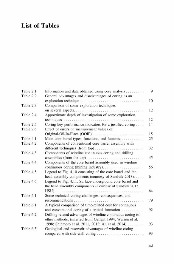
Table 2.1 Information and data obtained using core analysis . . . . . . . . . 9Table 2.2 General advantages and disadvantages of coring as an
exploration technique . . . . . . . . . . . . . . . . . . . . . . . . . . . . . . . 10Table 2.3 Comparison of some exploration techniques
on several aspects. . . . . . . . . . . . . . . . . . . . . . . . . . . . . . . . . . 12Table 2.4 Approximate depth of investigation of some exploration
techniques . . . . . . . . . . . . . . . . . . . . . . . . . . . . . . . . . . . . . . . 12Table 2.5 Coring key performance indicators for a justified coring . . . . 14Table 2.6 Effect of errors on measurement values of
Original-Oil-In-Place (OOIP) . . . . . . . . . . . . . . . . . . . . . . . . . 15Table 4.1 Main core barrel types, functions, and features . . . . . . . . . . . 25Table 4.2 Components of conventional core barrel assembly with
different techniques (from top) . . . . . . . . . . . . . . . . . . . . . . . . 32Table 4.3 Components of wireline continuous coring and drilling
assemblies (from the top) . . . . . . . . . . . . . . . . . . . . . . . . . . . . 45Table 4.4 Components of the core barrel assembly used in wireline
continuous coring (mining industry) . . . . . . . . . . . . . . . . . . . . 56Table 4.5 Legend to Fig. 4.10 consisting of the core barrel and the
head assembly components (courtesy of Sandvik 2013) . . . . . 64Table 4.6 Legend to Fig. 4.11. Surface-underground core barrel and
the head assembly components (Courtesy of Sandvik 2013,HSU) . . . . . . . . . . . . . . . . . . . . . . . . . . . . . . . . . . . . . . . . . . . 64
Table 5.1 Some technical coring challenges, consequences, andrecommendations . . . . . . . . . . . . . . . . . . . . . . . . . . . . . . . . . . 79
Table 6.1 A typical comparison of time-related cost for continuousand conventional coring of a critical formation . . . . . . . . . . . 92
Table 6.2 Drilling related advantages of wireline continuous coring toother methods, (inferred from Gelfgat 1994; Warren et al.1998; Shinmoto et al. 2011, 2012; Ali et al. 2014) . . . . . . . . 93
Table 6.3 Geological and reservoir advantages of wireline coringcompared with side-wall coring . . . . . . . . . . . . . . . . . . . . . . . 93
xxi

Table 8.1 A generic core trip schedule for conventional coring inshale-gas reservoirs (Zubizarreta et al. 2013) . . . . . . . . . . . . . 127
Table 8.2 Another generic core trip schedule for conventional coringin shale-gas reservoirs . . . . . . . . . . . . . . . . . . . . . . . . . . . . . . 127
Table 9.1 Reasoning for observations in the drilling parameters whilecoring . . . . . . . . . . . . . . . . . . . . . . . . . . . . . . . . . . . . . . . . . . . 142
Table 10.1 Type and size of scribe knives used to mark scribe lines onthe core based on formation type . . . . . . . . . . . . . . . . . . . . . . 156
Table 10.2 EMS and MMT specifications (published courtesy of BakerHughes GE) . . . . . . . . . . . . . . . . . . . . . . . . . . . . . . . . . . . . . . 159
Table 11.1 Pseudo-pressure coring parameters (published courtesy ofReservoir Group) . . . . . . . . . . . . . . . . . . . . . . . . . . . . . . . . . . 164
Table 12.1 Different methods of downhole logging of the core intervalof the formation . . . . . . . . . . . . . . . . . . . . . . . . . . . . . . . . . . . 173
Table 12.2 Comparison of different methods of downhole loggingof the core interval (inferred from Goldberg et al.2003, 2004, 2006) . . . . . . . . . . . . . . . . . . . . . . . . . . . . . . . . . 175
Table 12.3 Specifications and performance of the RAB tool(Goldberg et al. 2003, 2004) . . . . . . . . . . . . . . . . . . . . . . . . . 180
Table 12.4 Main components of DSS-RMM system and their functions(data gathered from Myers et al. 2006; Goldberg et al. 2003,2004, 2006) . . . . . . . . . . . . . . . . . . . . . . . . . . . . . . . . . . . . . . 183
Table 12.5 The dimensions used in DSS-RMM system (data gatheredfrom Goldberg et al. 2006). . . . . . . . . . . . . . . . . . . . . . . . . . . 184
Table 12.6 The development process of DSS system (for near real-timemeasurement of the drilling dynamic data) (data gatheredfrom Goldberg et al. 2003, 2004, 2006) . . . . . . . . . . . . . . . . . 186
Table 15.1 Detailed specifications of conventional coring (publishedcourtesy of Baker Hughes GE). . . . . . . . . . . . . . . . . . . . . . . . 216
Table 15.2 Detailed specifications of conventional coring (publishedcourtesy of NOV). . . . . . . . . . . . . . . . . . . . . . . . . . . . . . . . . . 218
Table 15.3 Specifications of wireline continuous coring systems(courtesy of NOV) . . . . . . . . . . . . . . . . . . . . . . . . . . . . . . . . . 220
Table 15.4 Conventional and soft-pro coring systems (publishedcourtesy of Reservoir Group) . . . . . . . . . . . . . . . . . . . . . . . . . 222
Table 15.5 Specifications of wireline continuous coring with pressurecoring (published courtesy of Reservoir Group) . . . . . . . . . . . 223
Table 15.6 Specifications of sidewall coring systems (publishedcourtesy of Halliburton) . . . . . . . . . . . . . . . . . . . . . . . . . . . . . 224
Table 15.7 General specifications of coring systems (publishedcourtesy of Halliburton) . . . . . . . . . . . . . . . . . . . . . . . . . . . . . 224
Table 15.8 Specifications of conventional full-closure coring system[field units] (published courtesy of Halliburton) . . . . . . . . . . . 224
xxii List of Tables
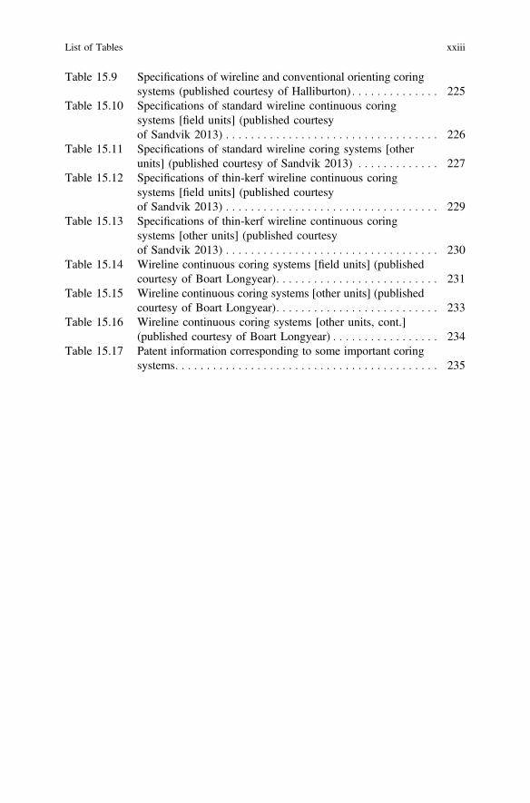
Table 15.9 Specifications of wireline and conventional orienting coringsystems (published courtesy of Halliburton) . . . . . . . . . . . . . . 225
Table 15.10 Specifications of standard wireline continuous coringsystems [field units] (published courtesyof Sandvik 2013) . . . . . . . . . . . . . . . . . . . . . . . . . . . . . . . . . . 226
Table 15.11 Specifications of standard wireline coring systems [otherunits] (published courtesy of Sandvik 2013) . . . . . . . . . . . . . 227
Table 15.12 Specifications of thin-kerf wireline continuous coringsystems [field units] (published courtesyof Sandvik 2013) . . . . . . . . . . . . . . . . . . . . . . . . . . . . . . . . . . 229
Table 15.13 Specifications of thin-kerf wireline continuous coringsystems [other units] (published courtesyof Sandvik 2013) . . . . . . . . . . . . . . . . . . . . . . . . . . . . . . . . . . 230
Table 15.14 Wireline continuous coring systems [field units] (publishedcourtesy of Boart Longyear). . . . . . . . . . . . . . . . . . . . . . . . . . 231
Table 15.15 Wireline continuous coring systems [other units] (publishedcourtesy of Boart Longyear). . . . . . . . . . . . . . . . . . . . . . . . . . 233
Table 15.16 Wireline continuous coring systems [other units, cont.](published courtesy of Boart Longyear) . . . . . . . . . . . . . . . . . 234
Table 15.17 Patent information corresponding to some important coringsystems. . . . . . . . . . . . . . . . . . . . . . . . . . . . . . . . . . . . . . . . . . 235
List of Tables xxiii

About the Authors
Dr. Rahman Ashena (Soroush) completed his Masterand Ph.D. degrees in Petroleum Well Engineeringrespectively at Curtin University (Australia) in 2009,and Montanuniversität Leoben (Austria) in 2017. Thetopic of his Ph.D. dissertation was on an innovativegeomechanics approach in core tripping. Backed upwith around five years of field work experience as asenior well completion/workover and drilling supervi-sor engineer, Ashena is specialized in well operationsand engineering (including well control, geomechanics,wellbore fluid flow modeling, well integrity manage-ment, and coring). In addition to his industry experi-ence, Ashena has more than seven years’ experience oflecturing drilling and completion courses. Ashena haspublished several technical papers with internationalpublishers including SPE, Elsevier, EAGE, and Taylor& Francis. He has also authored a book chapter in“Artificial Intelligent Approaches in PetroleumGeosciences”, Springer and a handbook on cementbond logging and evaluation.
xxv

Prof. Gerhard Thonhauser has 20 years of experi-ence providing the petroleum industry with the eval-uation, analysis, and management of drilling andwell-related data. He is the founder of TDE GroupGmbH servicing the international industry with drillingperformance analysis and benchmarking, as well assoftware, electronics, and equipment development andmanufacturing. Since 2003, he is Professor at theMontanuniversität Leoben, Austria and holds the Chairof Drilling and Completion Engineering and acts as theHead of the Petroleum Engineering Department. Hisareas of research and development include “DrillingProcess Monitoring and Analysis” combining model-ing, advanced monitoring and sensing, and drillinganalysis to optimize and automate the drilling processand to improve learning and knowledge management indrilling organizations. He has authored and co-authoredaround 100 publications in the area of drilling and com-pletion engineering and data science. Since 2009, heis the head of “Environmental Friendly DrillingSystems” initiative in Europe focusing on drilling andcompletion technologies with “Zero Harmful Environ-mental Impact”. He holds a Masters and a Ph.D.degree in Petroleum Engineering from the Mon-tanuniversität Leoben, Austria. He is also an activemember of SPE.
xxvi About the Authors