core.ac.uk · I SECURITYCLASSIFICATIONOFTHISPAGE(WhmnDmtmEntered) REPORTDOCUMENTATIONPAGE...
297
Calhoun: The NPS Institutional Archive Theses and Dissertations Thesis Collection 1984-06 Application of a silicon complier to VLSI design of digital pipelined multipliers Carlson, Dennis J. http://hdl.handle.net/10945/19164
Transcript of core.ac.uk · I SECURITYCLASSIFICATIONOFTHISPAGE(WhmnDmtmEntered) REPORTDOCUMENTATIONPAGE...

Calhoun: The NPS Institutional Archive
Theses and Dissertations Thesis Collection
1984-06
Application of a silicon complier to VLSI design of
digital pipelined multipliers
Carlson, Dennis J.
http://hdl.handle.net/10945/19164


DUDLEY KJ
NAVAL POSTGRADUATE SCHOOL
MONTEREY, CALIFORNIA 93943


NAVAL POSTGRADUATE SCHOOL
Monterey, California
THESISAPPLICATION OF A SILICON COMPILER TO
VLSI DESIGN OFDIGITAL PIPELINED MULTIPLIERS
by
Dennis J. Carlson
June 19 84
Thesis Advisor: D. E. KirkApproved for public release; distribution unlimited.
1217J\


I
SECURITY CLASSIFICATION OF THIS PAGE (Whmn Dmtm Entered)
REPORT DOCUMENTATION PAGE READ INSTRUCTIONSBEFORE COMPLETING FORM
1. REPORT NUMBER 2. GOVT ACCESSION NO. 3. RECIPIENT'S CATALOG NUMBER
4. TITLE (mnd Subtitle)
Application of a Silicon Compiler toVLSI Design ofDigital Pipelined Multipliers
5. TYPE OF REPORT 4 PERIOD COVEREDMaster's ThesisJune 19 84
6. PERFORMING ORG. REPORT NUMBER
7. author^;
Dennis J. Carlson
8. CONTRACT OR GRANT NUMBERf*)
9. PERFORMING ORGANIZATION NAME AND ADDRESS
Naval Postgraduate SchoolMonterey / California 9 3943
10. PROGRAM ELEMENT. PROJECT, TASKAREA 4 WORK UNIT NUMBERS
II. CONTROLLING OFFICE NAME AND ADDRESS
Naval Postgraduate SchoolMonterey, California 93943
12. REPORT DATE
June 198413. NUMBER OF PAGES
U. MONITORING AGENCY NAME 4 ADDRESS^/ different from Controlling Office' 15. SECURITY CLASS, (of thle report)
Unclassified15«. DECLASSIFICATION/ DOWNGRADING
SCHEDULE
16. DISTRIBUTION STATEMENT (of this Report)
Approved for public release; distribution unlimited.
17. DISTRIBUTION STATEMENT (ol the mbetract entered In Block 20, It different hoax Report)
18. SUPPLEMENTARY NOTES
19. KEY WORDS (Continue on reverse tide If neceeamry mnd Identify by block number)
VLSI Design, MacPitts, Pipelined Multipliers, Silicon Compiler,CAD Tools
20. ABSTRACT (Continue on reverse aide It neceeeary mnd Identify by block number)
The concept and application of silicon compilers is described.The process of employing the MacPitts silicon compiler to designan 8-bit pipelined digital multiplier is presented, and the re-sulting design is evaluated. The process of installing and de-bugging the MacPitts compiler and the Caesar VLSI graphics editoron the VAX 11/780 computing facilities at NPS is documented inappendices.
do ,;FaT73 1473 EDITION OF 1 NOV «5 IS OBSOLETE
S/N 0102- LF-014-6601 1SECURITY CLASSIFICATION OF THIS PAGE (When Dmtm Bntmrmd)


Approved for public release; distribution unlimited
Application of a Silicon Compiler to?LSI Design of
Digital Pipelined Multipliers
by'
Dennis J. Carlsonlieutenant Comman der/' United States Navy
E.S., Rensselaer Polytechnic Institute, 1969
Submitted in partial fulfillment of therequirements for the degree of
MASTER OF SCIENCE IN ELECTRICAL ENGINEERING
from the
NAVAI POSTGRADUATE SCHOOLJune 1984

C./

ABSTBACT
The concept and application of silicon compilers is
described. The process of employing the MacPitts silicon
compiler to design an 8-bit pipelined digital multiplier is
presented, and the resulting design is evaluated. The
process of installing and debugging the MacPitts Compiler
and the Caesar VLSI graphics editor on the VAX-1 1/780
computing facilities at NPS is documented in appendices.


TABLE OF CONTENTS
I. IKIECDUCTION 11
A. BACKGROUND 11
E. CURRENT RESEARCH GOALS 12
II. AEEECACHES TO SILICON COMPILATION 15
A. VLSI DESIGN ACTIVITIES DOMAIN 15
E. EVALDATICN CAVEAT 17
C. LIMITED SEECTRUM COMPILERS (TRANSLATORS) • . 18
E- BRO A E- SPECTRUM SILICON COMPILERS 19
1. Floor Planners 19
2. Behavioral Specification Compilers .... 21
III. USING MACPITTS 30
A. THE INPUT FILE 30
1. Fundamentals of the MacPitts Language . . 30
2. Two Multiplier Examples 36
B. INVOCATION OPTIONS 42
C. USE OF TEE MACPITTS INTERPRETER 46
E. EVOLUTION OF THE 8 BIT PIPELINED
MULTIPLIES 49
1. Design Motivation and Constraints .... 49
2. First Design: 3 Stages, 8 Bits on One
Chip 50
3. First Eartitioning: 2 Bits, 1 Stage
Pipeline 51
4. Second Partitioning: 4 Bits, 2 Stage
Pipeline 54
5. Third Eartitioning: 2 Bits, 4 Stage
Pipeline 57


E. DESIGN VAIIDATICN 60
1. Functional Simulation 60
2. Design Rule Checking 63
3. Node Extraction and Event Simulation ... 66
F. SUMMARY Cf ACTIVITIES IN THE MACPITTS
DESIGN CICIE 68
IV. MACPITTS PERFORMANCE 72
A. LAYOUT ERRORS AND INEFFICIENCIES 72
1- Inefficiencies 72
2. Errors 75
E. ORGANELLES VS. STANDARD CELLS 77
C. SOFTWARE INCOMPATIBILITIES ... 78
V. CONCLUSION 79
A. SUMMARY 79
E. RECCMMENIATIONS 80
APPENDIX A: INSTALLATION OF MACPITTS ON VAX-11/780
UNDER UNIX 4.1 AND 4.2 81
A. INSTALLATION UNDER UNIX 4.1 OPERATING
SYSTEM 81
E. INSTALLATION UNDER UNIX 4.2 OPERATING
SYSTEM 85
APPENDIX E: INSTALLATION OF THE CAESAR VLSI EDITOR
UNDER UNIX 4.1 AND 4.2 88
A. INSTALLATION UNDER UNIX 4.1 88
E. INSTALLATION UNDER THE UNIX 4.2 OPERATING
SYSTEM 89
APPENDIX C: MANUAL EAGES FOR EERKELEY DESIGN TOOLS ... 91
APPENDIX E: SIMULATION RESULTS FOR MULTIP8C
MULTIPLIER 122


APPENIIX E: LAYCUT fECTOGRAPHS 131
1IST 01 REFERENCES 137
EIBLICGR1PHI 139
INITIAI DISTRIBUTION IIST 140


LIST OF TABLES
I. Statistics For HacPitts Multiplier Chip
Designs ..61II. MacPitts Source Files 82


IIST OF FIGURES
2.1 VLSI Design Activities Spectrum 16
2.2 Typical floor plan produced by the
F.I.R.S.T. Silicon Compiler 20
2.3 Floor Plan cf the MacPitts Target
Architecture 23
2.4 MacPitts Register Circuit and Timing Diagram . . 25
2.5 MacPitts Program Data Flow 27
3. 1 Multic. mac Source File 37
3.2 Example of the Multic Behavioral
Specification 40
3.3 Multip.mac Source file 41
3.4 Compiler Statistics for multip 43
3.5 A MacPitts Interpreter Session for multip ... 48
3.6 Multip8.mac Source File 52
3.7 Multip8.mac Source File (Continued) 53
3.8 Use of Ports and Registers in multip8.mac ... 54
3.9 Data Path Architecture of Multip8 Chip 55
3.10 Block Diagram of First Partitioning 56
3.11 Multip8a.mac Source File 57
3.12 Multip8r.mac Source File 58
3.13 Multip8c.mac Source File 59
3.14 Values: Program to Compute Multip8c Output . . 64
3.15 Mextra .log File for Mul8c.cif 66
3.16 Two Macro Driver Files for Event Simulation . . 67
4.1 Data Path Ouput Routing 74
D.1 Macpitts Interpreter Results 122
B.2 MacPitts Interpreter Results, (continued) . . 123
D.3 MacPitts Interpreter Results, (Continued) . . 124
8


B.4 MacPitts Interpreter Besults, (Continued) . . 125
E.5 MacPitts Interpreter Besults, (Continued) . . 126
E.6 MacPitts Interpreter Besults, (Continued) . . 127
E.7 Event Simulation Besults 128
D.8 Event Simulation Besults, (Continued) .... 129
E.9 Event Simulation Besults, (Continued) .... 130
E.1 multic (top), multip (not) 132
E.2 multip8 (top), multip8a (hot) 133
E.3 multip8b (tcp) , multip8c5 (not) 134
E.4 multip8c4 (top), multip8c4d (bot) 135
E.5 layout Errors in kchip2 136


ACKNOWLEDGEMENTS
I would like to thank the following individuals fcr
their assistance in the completion of this thesis:
Naval Postgraduate School
Dr. Donald Kirk
Prcf. Robert Strum
Dr. Herschel Loomis
Mr. Al Hong
Massachusetts Irstitute of Technology
licccln Laboratory
Mr. Kenneth 5. Crouch
Dr. Antun Dcmic
University of California at Berkeley
Dr. John K. Custerhout
Dr. Keith Sklower
Stanford University
Dr. Robert Mathews
Ms. Susan Taylor
University of Kansas
Dr. Gerry L. Kelly
10


X. INTRODUCTION
A. EACKGECOND
The initial work done on the design of very large scale
integrated circuits (VLSI) at the Naval Postgraduate School
(NPS) used a set of software tools which require designer
interaction at all levels of the design process. These
tools and their use is described in a recent thesis by
Conradi and Hauenstein £Hef. 1 ]•
Their design approach centers around the use of: (1)
machine-generated programmable logic arrays (PLA's) speci-
fied in a language which translates boolean equations into
circuit layouts, and (2) a library of standard cell layouts
from which other reguired circuit primitives are selected.
The designer arranges the PLA's and standard cells en a
"floorplan" designed by heuristic methods, and interconnects
them with a network of individual wires devised by the
designer and encoded as a "wirelist. " The floorplan layout
and addition of interconnecting wires must be done manually,
typically on graph paper at the drawing board- The results
are manually encoded in an input file format readable by a
layout language program ("ell" in the case of the cited
research) which merges the designer's floorplan and wirelist
with: (1) the selected library cell layout descriptions and
(2) the PLA layout descriptions produced by the separate PLA
generaticn program. The circuit layout program then
produces a description of the total design in another stan-
dard file interchange format, the Caltech Intermediate Form,
(CIF) described by Mead and Conway [Hef. 2: pp. 115-127].
The CIF file can then be used as a source for extracting
design validation information, as well for producing the
photographic masks used for circuit fabrication.
11


The design process outlined has the advantage of giving
the designer thorough control over the architecture of the
circuit. The human ability to evaluate alternatives, recog-
nize patterns and grasp complex multi-dimensional relation-
ships between individual elements and the whole design
exceeds that of any current machine algorithm.
Cn the ether hand, this process absorbs large amounts of
the designer's time in performing the drudgery of planning
and encoding the layout details. There are at least four
things wrong with involving the designer at this level:
(1) It is repetitious work, and therefore error-prone.
(2) It is slow. (Southard [Ref. 3] and others have noted
that design costs far outweigh production costs for custom
VLSI.)
(3) Preoccupation with mechanical details restricts a
designer's freedom to explore high-level architectural
issues such as bus structure, degree of pipelining, and
speed-complexity tradeoffs.
(4) Major modifications to the layout are very expensive to
make if they come late in the design cycle, i.e. after cell
interconnection.
£. COBBENT BESEARCH GOALS
With this background for motivation, it was decided to
investigate additional VLSI computer-aided design tools
which would reduce time- to- design, minimize the occurrence
of human error in layout, and make it possible to explore
design alternatives with greater ease.
The major tool available in the VLSI research community
for this purpose is MacPitts. MacPitts (the name is derived
from two early researchers, Mcculloch and Pitts who studied
neurological systems from a mathematical and logic stand-
point) is a silicon compiler developed at the Massachusetts
12


Institute of Technology's Lincoln Laboratories in 1981-1982
[fief. 4]. A silicon compiler, according to one recent defi-
nitioD [Bef. 5] which captures current usage of this cften
misunderstood term, is "a program that, given a description
of what a circuit is supposed to do, will produce a chip
layout that implements that function in silicon." There is
enough latitude to allow fundamentally different approaches
to silicon compilaticc to coexist under this definition, as
will re demonstrated in the following chapter. In any case,
however, the term compiler is apt. Like software compilers,
these programs take high-level source code descriptions
which are human-readable (and perhaps, but not necessarily,
algorithmic) and "convert" them into low-level object code
(a CIP file) which is directly readable by a machine. In
the case of a siliccr compiler, however, the machine is not
a general-purpose computer, but a photo-resist mask gener-
ator at a silicon foundry facility that fabricates inte-
grated circuits.
Another function that the most advanced silicon
compilers perform is resource allocation. Software
compilers free the programmer from making decisions on where
in available memory space to store a particular machine code
word. Silicon compilers, at their best, free the designer
from deciding where en available silicon area to place a
particular circuit element. Resource allocation is a one-
dimensioDal job in software compilers, but a two-dimensional
job in silicon compilers. The constraints on efficient
resource allocation in silicon are severe—compactness is
almost always one goal, as is speed of operation (minimum
propagation delay.) In memo ry allocation, compactness is not
essential, unless one is using a sequential access memory.
Installation of MacPitts on the NPS VAX- 11/780 computer
facility was expected to be a "turn-key" operation. This
was in fact not the case. A large amount of effort was
13


spent in researching and performing the modifications to the
host ccitputer environment which enable it to run the
MacPitts system, as well as in troubleshooting the distrib-
uted MacPitts source code itself. The installation process
is described in Appendix A.
MacPitts has no progressive breakpoint facilities to
allow a designer freedom to observe or alter the layout
process at any point during execution. Once invoked,
MacPitts produces a final interconnected layout, complete
with tending pads, or no layout at all. Therefore, it was
considered worthwhile to implement the color graphics
editor, Caesar, designed by John Ousterhout at the
University of California at Berkeley [fief. 6]. This tool
allows the chip layout to be examined in detail on a color
CRT monitor, and permits editing of the layout. Caesar
represents the layout internally as a hierarchy of cells,
which yields insight into the ways that MacPitts partitions
the layout process.
The installation of Caesar, while not as difficult as
MacPitts, involved setting some site-dependent parameters as
well as finding and correcting a bug in the distributed
source cede. These activities are described in Appendix B.
Appendix C contains a copy of the on-line manual pages for
Caesar and ether Berkeley tools used in this research.
14


II. APPROACHES TO SILICON COMPILATION
A. TflSI DESIGH ACTIVITIES DOMAIN
flhen trying to understand how silicon compilers work it
is instructive to think of two design problems in the order
in which they must be attacked. The first is translation of
a brief behavioral or functional description into a mere
precise intermediate description that is still independent
of the specific implementation technology- The second is
the automatic generation of a chip layout in a target semi-
conductor medium, using the intermediate description as a
guide. It is important to separate the second activity from
the first when one is designing a silicon compiler because
of the speed at which the target semiconductor technologies
are evolving. That is, complementary metal oxide semicon-
ductor (CMOS) processes are rapidly overtaking N-channel
metal oxide semiconductor (NMOS) processes. Multiple-layer
metalization is also becoming more common, and minimum
circuit feature sizes are shrinking as better control over
the manufacturing processes is achieved. Computer architec-
tures and functions evolve more slowly, by comparison.
These two problems may be further subdivided. Werner
[Eef. 7] has contributed the idea that a spectrum of VLSI
design activities exists with corresponding media for the
exchange of information by the computer-aided design tools
employed at each band in the spectrum. (See figure 2.1.)
Silicon compilers try to span the whole spectrum, an ambi-
tious undertaking.
15


w • : -
1 Geomel (Mask-L 'Silicon
Descrip
• £J 3«o2 5 o sE £>. -
cc 1 §
f> J 3O
oc•
c•E
o3
VI
OO-3
ofl
o.
£i
3o>.m-j
u
1
•a3O)cfl
_»
|
tSymbolic
Represen
without
Compacti
2.a—i
uaE
E fl
3oo
8
u
fl
Epac
ription
or on
clion)
MCgaa Ol fl hi *« -2 wo
3<
fl
|
c>cou
3
im_i
E
1c
13
5u3
(S
a o — -
1 J> _ > » >
ui/i
aQaa< -1 1 1 aj
Ca c IL •
a>
so
o
(?)
O
a* 1 5
aEL E
o » »1 a
c© J23DO j2
Is~*
flffl hi^
^
1
c
a1 u
s§
o *o is
CQO• I v 5O ic£ c
•aa. c ufl
fl
QO
Olo s
« S a
o) c 5 v)a. ^ fl n fl
E u S^-iOo c
M U 3u.
fl
s•c u yc "2 a>. 10 a _
<fl r -i_ Eu5>o
01
2
n A A q>
a o § j»
_J A fl o u'
X 33 a. O
tI—
I
4-1
OS
9MMUcu
w0)
•H
•H
•H•PO
a
•HWVQHHi
'V
us
•H0*
16


E. EVALUATION CAVEAT
It should be recognized that all silicon compilers
designed to date have to some extent traded performance of
the ultimate VLSI design (as measured by operating speed and
area efficiency) for reduced design time for the chip (and
for the silicon compiler itself.) Gross £Be£- 8] quotes
estimates for reduced design costs (time) by use cf tread
spectrum silicon compilers to be a factor of 20. But
Wallich, in a recent survey of silicon compiler efforts
[Hef, 5 J, states that designs produced by silicon compilers
available today tend to range from 1 5 to 200 percent larger
than equivalent hand-crafted designs.
Still, silicon compilers have been misunderstood by
researchers as noted by Gross. Some, without fully under-
standing the dimensionality of the VLSI design process,
believe that the design problem can be almost completely
solved by the application cf current software methods and
tools. Others, seeing the obvious limitations of contempo-
rary siliccn compilers and not grasping the potential
contributions to VLSI from computer science technclogy
transfer, believe that efficient VLSI designs will always be
essentially manual. Murphy of Bell Laboratories, guoted by
Werner [Hef. 7], states that "total automation is
inappropriate— either now or in the foreseeable future—in
anything where ycu have a competitive need for performance.
"
Nevertheless, Bell labs is conducting research of its own
into silicon compilers. Their "Plex" project reported in a
more recent paper £Bef . 9 ] produces layouts of microcom-
puters given, as input, the progra m (in assembly or C
language) that the microcomputer is to execute.
According to Wallich, the ultimate silicon compiler, now
just a dream, will not only be able to take a behavioral
description and produce a geometrical description of the
17


chip suitable for input to a mask making machine, tut will
do sc for anv. kind of chip—microprocessor, signal
processor, or even analog-digital hybrid for which the
design rules are far more complex. The subtle process of
architectural optimization (i. e. selecting a best floor
plan frcm the myriad possibilities,) which occurs in the
middle of the design activities spectrum, has so far not
been captured in an algorithm. To achieve some breadth
without teing overwhelmed by complexity, silicon compilers
have tended to contain built-in assumptions about a "target
architecture." They are optimized for producing a certain
class of circuits—mostly microprocessors— and produce
layouts cf reasonable area and speed only for applications
test suited to their target architecture.
C. IIBITED SPECTRUM COMPILERS (TRANSLATORS)
Fcr completeness, it is necessary to mention these VLSI
design tools in current use which fall short of covering the
design spectrum. They are:
• Eandcm logic/Standard-cell place-and-route systems,
• Module compilers to implement boolean logic, including:
• Gate array compilers,
• FLA generators,
• Regular expression compilers for
finite-state machines,
• layout languages,
• Interactive graphical layout editors.
18

D- EBOAr-SFECTBUfl SI1ICON COMPILERS
1 • floor Pl anne rs
a. Common Properties
The first broad spectrum translators of interest
are the fleer planners. They all employ a struc tural speci-
fication language in which the specification always corre-
sponds extremely closely to a description of the designees
mental model of how the chip should be laid out. They
produce, as an initial output, a skeleton of the layout
similar to an architects floor plan. Subsequently, floor
planners fill the "rooms" with cells from a standard
library. Some floor planners, of which Johannsen's Bristle
Blocks is a pioneering example £Eef. 10], can linearly
stretch cells to match up the interconnections of abutting
cells (sc-called "pitch matching.")
£. r.I.B.S.i.
The current state of the art in floor planners
is represented by the F.I.E.S.T. (Fast Implementation of
Eeal-Time Signal Transforms) silicon compiler developed at
Edinburgh University £Ref. 11]. The F.I.E.S.T. compiler
produces layouts of digital signal processing systems imple-
mented as hard-wired networks of pipelined bit-serial opera-
tors. The floor plan of F.I.E.S.T. chips (see figure 2.2)
consists of a central wiring channel with operators arranged
as function blocks arcund the "waterfront." Each bit-serial
operator is implemented as a separate function block which
in turn is assembled from a library of hand- designed cells.
The function blocks are arranged, in the order of their
high-level specification by the designer, in two rows along
either side of the wiring channel which accommodates all
interconnections between the blocks. This uncomplicated and
19


PADS1
OPERATORS
1
WIRING CHANNEL
HDP
1 1
PADS
Figure 2.2 Typical floor plan produced by theF. I.fi.S.T. Silicon Compiler.
novel layout methodology results in the non-use of about 20%
of the total chip area (because the blocks may have varied
heights.) At present, F.I.R.S.T. supports only the
N-channel metal oxide semiconductor (NMOS) technology.
The F.I.R.S.T. software consists of a small
suite cf programs which provides the designer with a
complete specialized design environment. At the top level
is a language compiler that accepts a structural description
of the circuit in terms of a net list of bit-serial opera-
tors. The F-I.R.S.T. system contains a library of primitive
operators, {such as MULTIPLY, ADD, SORT, BIT DELAY, ETC.) as
well as a number of more complex procedural definitions
(such as Biguad, Lattice, Butterfly, etc.) that enable a
20


range of signal processing architectures. The language
compiler produces an intermediate level format file as
output. This file is used by both a layout program, which
produces the mask gecmetry, and a simulator. The simulator
is event driven, which means that the voltage values on
circuit nodes are modeled as discrete bits of data occurring
at discrete time intervals. The functioning of individual
operators is simulated on a word-by-word basis in response
to a file of input cemmands. It is asserted that the simu-
lator has the ability to uncover timing bugs in the data
stream.
A unique and useful aspect of F.I.E.S.T. is
incorporation of a translator program to convert the simula-
tor's output into a form suitable for use with an automatic
test pattern generator system.
2« Eehavioral Specification Compilers
a. Common Properties
In contrast to the floor planners, which accept
structural specifications at the top level, are the b ehav-
iora l specification compilers, which do not reguire the
designer to possess a prior mental model of the architecture
to be designed. These systems attempt to translate a high-
level behavioral description of the circuit into a geometric
mask description. This step is a significant one over floor
planners.
fc. Ayres' Work
Ayres is the first to have written a book-length
treatment of silicon compilation [Ref. 12]. Ayres' compiler
approach starts with a synchronous logic specification of
the chip behavior. Then follows a decomposition of this
specification repeatedly into a hierarchy of implementing
21


HMOS ELA's which become successively more area-eff icier.t as
they become smaller. The system includes heuristics to
manage and optimize cn-chip routing among the PLA *s gener-
ated. Ayres* compiler is potentially applicable to a
broader class of circuits than F.I.R. S.T., but is still not
efficient fcr a general range of problems. The sccpe of
applications was restricted intentionally to control
complexity. The very use of PLA's as the sole tasic
buildirg blcdc restricts the area efficiency of this system.
Even though the PLA's themselves become more area-efficient
as they become smaller, the difficulty of managing their
interconnections liiits the ultimate efficiency of the
layout.
c. MacPitts
MacPitts is the only broad spectrum silicon
compiler with which this author has had any first-hand
experience. It is also the most widely known and most ambi-
tious behavioral specification compiler in operation.
The hardware specification generated by MacPitts
is in the form of an KMOS technology CIF file. To cope with
the complexity of this project the designers restricted the
target architectures to microprocessors consisting of a data
path and a controller (see figure 2.3.) Other restrictions
include fixing the width of the data path to one value
throughout the design, and reguiring the designer to specify
control and parallelism explicitly. The latter is not actu-
ally a restriction in one sense, however, because it affords
greater generality in designs. Except for making pin
assignments, the MacPitts user has no explicit control over
the floor plan of his design. The MacPitts target architec-
ture results in the same basic floor plan for all designs,
although this particular architecture is applicable to a
greater variety of digital problems than any other scheme
presently available.
22


InputPorts
OutputPorts
I/CPorts
ClockBus(3 lines)
InputSignals'
OutputSignals
I/CSignals
+
PADS
DATA PATH
3
CONTROL
PADS
PADS
Figure 2,3 Floor Plan of the MacPitts Target Architecture.
The data path portion of the layout consists of
a rectangular array of units called "organelles." An orga-
nelle is a tit-wise functional unit. A standard lirrary of
functions— adder, subtracter, shifters, incrementers, compa-
rators, etc.— is provided. Also, if the algorithmic
23


behavior specificaticn calls for conditional data flew or
looping, the data path may also include multiplexers which
have connections for control signals- This multiplexer
organelle is not a library cell but is built into MacPitts.
Data storage registers, implemented as master-slave flip-
flops, are also "built-in organelles." These are instanti-
ated in the data path if their use is implied by the
algorithmic specification.
The vertical dimension of the data path outline
in figure 2.3 corresponds to the number of bits in the data
word. Longer word-lengths produce a taller chip. The
various organelles are cascaded along the horizontal dimen-
sion of the data path outline.
The control portion of the layout acts on
various signals, either derived from the data path or
outside the chip, ard implements whatever boolean logic is
necessary (as inferred from the algorithmic specification)
to generate controls signals to drive the multiplexers in
the data path. The result is an implementation of a finite
state machine, (FSM) as described in Mead and Conway
[Bef. 2]. The control unit does not use PLA's, but rather
structural NOR gate arrays called "Weinberger Arrays" which
can inplement arbitrary combinational logic functions.
Weinberger [Bef. 15] demonstrates that his logic arrays have
three features which contribute to efficiency in an auto-
mated circuit layout scheme.
• They simplify the formation of interconnection patterns
within the framework of a standardized layout.
• They significantly reduce the required area (by elimi-
nating unused inputs and separate interconnection
areas.)
• They eliminate crossing of signal nets (by using single
level wiring.)
24


State tilting is controlled not by a two-phase
non- overlap ping clock, which is somewhat standard in NMOS
VLSI, tut by a three-phase clock which drives the register
circuit shown in figure 2.4. This clocking scheme appar-
ently allows a more compact layout of the register orga-
nelle, but requires an extra pin in the package.
Input
phia
i_r
\>
-O^
D» Output
Tphib phic
tl t2 t3 t4 t5
phia
phib
phic
Output)(
tl
t2
t3
t4
t5
static storage
isolate output
sample input
isolate input
connect to output
Figure 2.4 HacPitts Register Circuit and Timing Diagram.
25


One of the authors of MacPitts, Siskind quoted
in [B€f. 7], admits that optimizing chip performance was not
a primary design gcal. Circuit densities reported were
80-100 transistors per square millimeter in 5 micron feature
size KMOS—approximately 2 orders of magnitude lower than
the state cf the art layouts reported in Gross [Ref . 8].
Southard contends that the cells he helped desigr for
MacPitts cculd fairly easily have been made 20 per cent
smaller than they are [Ref. 5].
MacPitts only produces NMOS output in CIF, tut
the user has a choice of either 4 or 5 micron minimum
feature size, which the compiler handles by linearly scaling
all features except the pads. The latter are contained in
two separate libraries for 4 micron and 5 micron designs.
From the programming viewpoint, MacPitts is a
very complex system. It consists of a binary executable
module of ever 1.5 megabytes which was built up as a LISP
programming environment and then dumped, as described in the
Franz lisp manual £Bef. 13]. A synopsis of the functional
elements which make up this LISP environment is shown in
figure 2.5 . Unlike F.I.R.S.T., these programs (except the
functional simulator or "interpreter 11 as its authors call
it) are not individually accessible. MacPitts runs automat-
ically from beginning to end with no possibility for oper-
ator intervention. The only control available at the
console when the compiler is running is the standard UNIX
system abort signal.
The authors of MacPitts were careful to separate
all the processing into technology independent (frcnt-end)
and technology dependent (back-end) portions, with the
intermediate-level description being the point of division.
This intermediate-level description is available to the user
as an "object file" in human readable form. It is possible,
although net very practical, to write an object file
26


IlSJ-like Behavioral Specification (Source File)
Prepass
£Data-PathExtractor
Normalizer
SequenceExtractor
1 IControlExtractor
Intermediate-level Description (Object File)
OrganelleLibrary
Data-EathLayout
I
IFunctionalSimulator
SeguenceLayout
L I
IControlLayout
Ii
1Router
CIF Generator ("L5")
Hask Level Description (CIF File)
Figure 2.5 MacPitts Program Data Flow.
directly for input to the back end of MacPitts. The object
file is a long list containing 5 elements, each element
being itself a list. The 5 elements are: definitions,
flags, data path, ccntrol, and pins. This list is, of
course, in a form readable by the layout programs.
The layout programs produce only NMOS tech-
nology. As mentioned above, two bonding pad libraries are
27


included: the Stanford standard cell library pads for 5
micrcn designs, and the MOSIS AEPA community pads for 4
micron designs. The "layout language" and CIF generation
program, 15, which is emredded in MacPitts, was written
especially for the project by Crouch £Ref. 14 ]• It has
built-in facilities to handle toth NMOS and CMOS technology
layouts. Therefore, expanding MacPitts to produce CMOS CIF
would not entail a comp lete rewrite of the back end
programs.
An important feature of the MacPitts software is
the functional simulator or interpreter. A MacPitts program
is not only an IC specification, it is also an algorithmic
specification. The interpreter executes the specification
program as a general-purpose computer using an interactive,
screen-oriented input/output style. By invoking this option
of MacPitts the user can exercise his design, thereby vali-
dating (to whatever extent the exercise is complete) its
functional fidelity. Once the functional simulation is done
to satisfaction, MacEitts can be restarted without setting
the interpreter opticn. This produces a finished layout and
corresponding CIF file. By using the same language to drive
both the interpreter and the integrated circuit compiler,
human error is reduced.
MacPitts lacks some features. It has ncne of
the capabilities of P.I.R.S.T. to produce a test pattern to
exercise the chip. It also lacks any built-in mechanism to
identify worst-case path delays or to predict the maximum
clock frequency of the finished chip. It does keep account
of conductivity information, however, which it uses to
predict chip power consumption.
MacPitts uses a "correct by construction"
doctrine in the layout process. By denying the user the
means to specify the layout details of the chip, this
approach also denies the user the opportunity to commit
28


design rul€ errors or to translate the specification program
into a con-corresponding layout. But can MacPitts itself
make design rule errors?
The following chapters examine how to use
MacPitts to produce an integrated circuit layout, hew to
validate the design, and where to look for ways to improve
chip performance.
29


III. OSING MACPITTS
A. TEE INPUT FILE
1. Fun damentals of the MacPitts Lan guage
"MacPitts," the system for generating a custcm inte-
grated circuit, is also "MacPitts," the language in which
the algorithm is specified. In this section the second
meaning is the one implied. All of the information which
specifies what functional behavior is. required of a VLSI
circuit is communicated to MacPitts in a single text file.
This file, which must have the extension ".mac", is written
using syntax which closely resembles that of the LISP
programming language. Because the MacPitts compiler is
implemented in LISP, it is reasonable to expect the syntax
of the MacPitts design language to follow the LISP paren-
thesized notation. This choice was made by the authors of
MacPitts because it eliminates the need for a separate
parser.
LISP is a list processing language. Its data
elements are "symbolic expressions" made up of "atoms"
(fundamental word-like objects separated by spaces) , lists
of atoms, lists of lists of atoms and so on. One of the
strengths of LISP is the ability to concatenate atoms or
lists into new lists, and to perform other operations on a
list cr a hierarchy of lists to produce new lists modified
in useful ways. LISP has many built in functional defini-
tions which are an "environment" of specifications fcr the
operations to be performed on lists. These definitions are
all contained in The Pranz Lis p Manua l [fief-.13]. In addi-
tion to using these definitions, the LISP user is free to
extend the LISP environment by defining new functions which
30


specify ether operations on lists- The types of operations
may he simple manipulations of the atoms by partitioning or
permutation, or, if the atoms which comprise the list happen
to be numbers, arithmetic operations may be performed. The
definitiens of the operations themselves may also be assem-
bled from lists cf mere primitive operational atoms. This
functional extension of operations is what the authors of
MacPitts have done in creating the MacPitts Lisp
environment.
The design of a VLSI circuit can be thought of as a
list-building process in which the lists are electrical
ports, registers, interconnection nets, data testing opera-
tions, and ultimately a string of words which define a
unique patterning of silicon in the mask level descriptive
language, CIF. These lists are built according to rules
contained in another list—the algorithmic specification
source file. Although the MacPitts design language resem-
bles IISI syntactically, its semantics is different and much
more limited. A powerful feature of LISP is, for example,
recursive definition. This feature is absent in the
MacPitts design language. A description of the MacPitts
grammar in Eackus normal form is given in [Eef. 4].
In its most general form, a MacPitts "program" to
specify a circuit's behavior consists of a set of
"processes," each of which executes sequentially, but all of
which run in parallel. The states of each process are
fundamentally disjoint from those of the other processes.
This allows the hardware for each process to run indepen-
dently of the other processes, if desired, and concurrently
with the states of the other processes, in any case. The
operations performed by a given process in a given state are
specified by a "form." Each form corresponds to a single
machine state, and is executed in one clock cycle. A state
may fce given a name by preceding the form with a label.
31


Normally execution proceeds sequentially from one state to
the following state in the .mac file at each clock cycle. A
"go" fori can be used, however, to deviate from this sequen-
tial flew by causing the named state to be executed next
instead of the syntactically following state.
Eata is communicated between the data path and the
external world through "ports" which have the same bit width
as the data path. Cnly a single data path width definition
is allowed per program. A port may be declared "input,"
"output," "tri-state output," or "i/o. " Ports may also be
declared as "internal," in which case they simply cascade
the output of one data path operation to the input of
another. The data path may also be specified to contain
registers. The difference between internal ports and regis-
ters is that registers can store data indefinitely after it
has been clocked in, whereas ports are only electrical nodes
in the data path and therefore do not store data. Ports
simply are arrays of named terminals for conducting data
from cne point to another.
Control of operations performed on the data by the
data path organelles is governed by the Weinberger array
control unit. Control outputs from the control unit to the
data path may determine, by means of their control over
multiplexer organelles within the data path, which opera-
tions occurring within the data path will affect downstream
organelles. Status outputs from the data path returning to
the control unit allow the seguence of operations performed
by the control unit to vary depending on the data present
either in the registers or at any other point in the data
path. The control unit functions may also be made to depend
upon external inputs. The control unit communicates with
the outside world using "signals," which are analogous to
the "ports" used by the data path except that each signal
appears on a single wire. Signals may be declared as
"input," "output," "tri-state output," "i/o" or "internal."
32


Operations performed by the data path during a given
state are specified by the IISP "setg" form- The setg
causes the data path to evaluate a seguence of operations on
either input port data, internal port data or register data.
(The setg may also be used with signals.) The result of
these specified operations is then conducted to another
named port or loaded into a data path register during the
next clock cycle. The compiler includes enough copies of
each operator in the data path so that separate processes,
intended to run in parallel, do not conflict over the
attempted shared use of a single resource. The data path
can cascade several operations together in a single form.
This allows forms such as the following example, which
computes a=b-c using 2*s complement arithmetic, to execute
in one clock cycle:
(setg a (+ b (1+ (not c) ) ) .
The list consisting of everything on the preceding line is a
single form. There are three operators in this expression:
"+," which specifies use of an adder, "1+" which specifies
an incrementer, and "not" which specifies an inverter. Each
operator is followed by its operands listed in sym bolic
notation. Therefore, the single operand of 1+ is the
integer that results from evaluatin g the expression "(not
c) . " Note that there is not a default hierarchy of opera-
tions within a form. As with LISP, the order of operations
in MacPitts must be specified explicitly by the use of
nested parentheses.
Seguences of setg forms normally operate seguen-
tially, each being executed on a separate clock cycle. By
enclosing the forms within another "parallelizing form," of
which "par" is an example, several forms can be made to run
in parallel, gaining speed over seguential operation at the
cost of more hardware and hence more area in silicon. The
par form is used as fellows:
33


(par fcrml form2 form3...)
Cf course the results obtained by running setq forms in
parallel may be quite different from those obtained by
running then: all sequentially within one process. Consider
the following example where "a" and "b" have already been
declared registers (i.e. master-slave flip flops)
:
(par (setq a b)
(setq b a)) .
This expression will result in exchanging the contents of
"a" with contents of "b." The exchange will be done in one
MacPitts clock cycle. This action is made possible by the
input isolation which occurs during the flip-flop operating
cycle. All such data storage elements are read before they
are written. On the ether hand, sequential operation of the
same setq's is implied in the following process:
(process loadl (setq a b)
(setq b a) ) .
This process will lead both b and a with the original
contents of b, and require two cycles to do it. (Here
"loadl" merely furnishes a process name, as demanded by the
MacPitts grammar.) Me have used two lines and indented
format only for the sake of clarity. All the functional
information needed by MacPitts is denoted by the ordering of
forms within the nests of parentheses.
The "cond" form allows the conditional execution of
ether forms it contains during a given state. It consists
of a list of guards, only one of which is to be executed.
Each guard begins with a "condition" which determines
whether the remaining forms in the guard are to be executed.
The first guard whose condition is true enables the execu-
tion cf the forms following the condition in that guard.
This is illustrated by the following example adapted from
[Hef. 4].
34


(ccnd (conditionl (cond (condition2 forml form2)
(condition3 form3 form4 form5)
(t form6))
)
(conditions (cond (condition5 form7 form8))
(cond (condition6 f orm9)
)
form 10))
This example is heavily nested. Nevertheless, close exami-
nation reveals that the outermost " (cond..." has only two
guards in its list, each of which contains other "(cond..."
forms. The two guards are:
(conditionl (cond (condition2 forml form2)
(condition3 form3 form4 form5)
(t form6)))
and
(condition*! (cond (condition5 form7 form8))
(cond (condition6 f orm9)
)
form 10)
If conditionl is false and condition4 is true then formlO is
executed. If condition5 is true then form7 and form8 are
executed along with fcrmlO- Likewise if condition6 is true
then fcrm9 is executed in parallel as well.
The semantics of the cond statement is inherently
parallel. The conditions of the alternate guards are
checked in parallel. Likewise, all forms within the guards
are executed simultaneously in one clock cycle. The
compiler makes the conditions of different guards in one
cond form mutually exclusive, and implements them using
combinational logic in the control unit as described atove.
This logic is used to enable or inhibit the execution of
forms controlled by that guard in parallel.
Note that the form:
35


(cond {t forml form2 form3 -.-))
is used to enable parallel execution of several forms during
one clock cycle without being dependent on any condition.
(The "t" stands for "true.") The "(par..." form already
encountered is actually just a shorthand macro expression
for the "(ccnd (t. .." form.
In a MacPitts layout, the conditions are fcrmed in
the control unit, which is a Weinberger array of NOR gates
[fief. 15]. Therefore, they are not limited to cnly the
sum-cf-prcducts notation used by PLA-based finite state
machine compilers. The conditions are derived frcm either
signals arriving on an input pin, signals from the data
path, cr signals arriving from other processes. Mere
complex conditions can be constructed from these signals
using the logical operators "and," "or" and "not" to tuild
arbitrary Boolean expressions. These operators are part of
the MacPitts library cf functions. Thus, the cond statement
is cne cf the most powerful features for providing high
performance designs.
Hith this brief and somewhat condensed description
of the features available in the MacPitts algorithmic
language, the way is prepared to to understand an example of
some code which will produce a complete integrated circuit
chip. A full detailed description of all the facilities of
MacPitts is found in a report authored by its creators
[fief. 16], which also serves as a fairly complete users*
manual.
2. Two Mul t iplie r Example s
Consider, line by line, figure 3.1 which is a
listing cf the file multic.mac. This example and the cne
which follows it are inspired by similar ones in [fief. 16].
It contains all of the design information needed by MacPitts
to produce a H bit combinational multiplier. On any line,
36


1 ; multiplier, no state combinational2 (program multic 4
3 (def 1 ground)4 (def ain port input (2345))5 (def bin port input (6 7 8 9))6 (def res port output (10 11 12 13)); result7 (def rO port internal)8 (def rl port internal)9 (def r2 port internal)
10 (def 14 phia)11 (def 15 phib)12 (def 16 phic)13 (def 17 power)14 (always15 (cond ((bit bin) (setq rO (>> (bit ain) ain)))16 (t (setq rO 0) )
)
17 (cond ((bit 1 bin) (setq rl (>> (bit (+ rO ain)) (+ rO ain))))18 (t (setq rl (>> (bit rO) rO))))19 (cond ((bit 2 bin) (setq r2 (>> (bit (+ rl ain)) (+ rl ain))))20 (t (setq r2 (>> (bit rl) rl))))
'
21 (cond ((bit 3 bin) (setq res (>> (bit (+ r2 ain)) (+ r2 ain)))22 (t (setq res (>> (bit r2) r2) ) ) ) )
)
Figure 3.1 Multic. mac Source File.
text following a semicolon is treated as a comment, which
the compiler ignores. Line 2 tells the compiler that a
"program" (which is another way ox saying, "circuit design")
called "multic" starts here, and that the data path is 4
tits wide. Because the data path is only 4 bits, this
simple multiplier will only be able to output numbers from
to 15. Even though the input ports are also four bits wide,
we must restrict input numbers to only those whose prcduct
falls in the range of values from to 15. Furthermore, if
this algorithm is to give correct results for all multi-
pliers, without overflow, the leading bit of the multipli-
cand must be zero. No provision is made to output a flag if
the dynamic range of the multiplier is exceeded.
lines 3 through 13 declare the various signals and
integer data words input to, output from and existing within
the multiplier. Line 3 assigns the ground connection to pin
1 which is always in the upper left corner of the layout;
37


subsequent pin numbers proceed clockwise from this point
around the layout perimeter. Line 4 assigns pins 2-5 to an
input port labeled "ain." This input is the multiplicand.
Ey MacPitts convention, the most significant bit (MSB) of
ain is read from the first pin on the list, pin 2, and the
least significant bit (LSB) from the last pin on the list,
pin 5. Line 5 similarly defines the multiplier input port,
"bin." line 6 assigns an output port labeled "res" (for
result) tc another block of 4 pins. This port also serves
as the accumulator fcr the fourth and final partial product,
lines 7 through 9 define 3 internal ports (necessarily of
width 4 tits) labeled rO, r1 and r2. These serve to cascade
the three stages of a standard shift and add algorithm.
Each port contains one of the first three partial products,
each being the result of operations conditioned on cne of
the multipler bits. Lines 10 through 12 assign pins tc the
three phase clock, whether that clock is used by the circuit
or not. In multic.mac the clock is not used. Line 13
defines the 5 volt direct current power, Vdd, connected to
pin 17.
line 14 signifies that the functions which fcllcw,
up to the matching right parenthesis on line 22, are to
execute en every clock cycle. The "(always..." form is
really the "(process..." form, reduced to a single state.
Moreover in this case, given the (always... form, and given
that the data path contains only ports and not registers,
the inputs will affect the result after an interval governed
only by the sum of the physical gate delays in the data path
and control unit. There is no controlled latency in the data
path, because there are no registers in this design in which
to store data.
lines 15 through 23 contain the shift and add
scheme. In lines 15 and 16 the controller is told to
examine bit (the LSB) of bin. If it is high (true) the rO
38


port takes on the value of the ain port rotated right by cne
hit, i.e. rO is actually connected by means of a multiplexer
organelle tc a right rotated version of ain. The shift-
right-one-bit form, "»," takes two arguments. The second
argument specifies what data word is being shifted, and the
first tells what to put in the MSB of that data word. Thus,
a rotate is also within the capabilities of the shift form,
as it is applied in this case. If bit of bin is not high,
then, by line 16, the rO port— all 4 bits— is connected to
ground. In lines 17 and 18 the controller is told to
examine hit 1 of bin- If it is high, then r1, the next
internal port in the data path, is connected to a right-
rotated version of the sum cf rO and ain. The adder orga-
nelle in MacPitts performs this summation as a standard
ripple carry full addition. Note again that the expression:
(bit (+ rO ain))
in line 17 turns the single shift operator into a right
rotate operator by making the MSB of r1 contain the same
value as bit of the sum of rO and ain. If bit 1 of bin is
low, on the other hand, line 18 instructs the controller to
connect r1 to simply a right-rotated version of rO. Note
that no rotations are being performed by any of these opera-
tions in the sense that a shift register would perform them.
It is only the interconnections between organalles that are
being set up variously by the controller to give an appear-
ance of forwarding a rotated version down the data path.
Also note that even though the addition form appears twice
in line 17, logically only one adder need be instantiated,
since the operands are identical in both occurrences.
MacPitts, tco, can recognize this, and will not waste space
creating more adders than the minimum necessary. In lines
19 and 20 the controller examines bit 2 of bin. If it is
high, port r2 is connected to a right-rotated version cf the
sum of r1 and ain. If bit 2 of bin is low, r2 is connected
39


to a right- rot a ted version of r1. In lines 21 and 22 the
controller finally examines the MSB, bit 3, of bin. If it
is high, the output port, res, is connected to a right-
rotated version of the sum of r2 and ain. If bit 3 of bin
is low, res is connected to a right rotated version of r2.
for ccncreteness, a schematic trace of this algorithm in
acticD on the problei "4x3=12" is presented in figure 3.2.
ain=40100
bin=30011
Algorithm Statement
-i*- (setq rO-7- (» (bit ain) ain))
*- (setq r1 (» (bitO""- { rO ain)) ( rO ain)))
*" (setq r2T" (» (bit r1) r1) )
(setq res(» (bit o r2) r2) )
Result
r0=20010
r1 = 30011
r2=91001
res=121100
Figure 3.2 Exaiple of the Multic Behavioral Specification.
Fcr comparison, consider now another design. This
one is specified by the file multip. mac shown in figure 3.3
This is a fcur bit pipelined multiplier in which the product
does net appear at the result port until the third clock
cycle after values have been applied to the inputs, ain and
tin. Changing the combinational design to a pipelined
design can most easily be accomplished in two steps. First,
40


1
2
3
4
5
6
7
8
9
10
111213141516171819202122232425262728
29303132333435363738394041
multprogr
(de(de(de(de(de(de(de(de(de(de(de(de(de(de(de(de(de(de(al(co
iplier, with pipeliningam multip 4
f 1 ground)f ain port input (2 3 4 5))f aO register)f al register)f a2 register)f bin port input (6789))f bO register)f bl register)f b2 register)f res port output (10 11 12 13))f rO register)f rl register)f r2 register)f 14 phia)f 15 phib)f 16 phic)f reset signal input 17)f 18 power)waysnd ((
(t
(cond (
(
(t
nd ((
(t
nd ((
(t
(r
(co
(CO
(cond
(t
bit bin)(setq rO
bit 1 bO)(setq rl
bit 2 bl)(setq r2
bit 3 b2)(setq res
eset (setq(setq(setq(setq(setq(setq(setq(setq(setq(setq(setq(setq
rO (>>(setq0)))(setq rl(>> (bit(setq r2(>> (bit(setq res(>> (bitaO 0)
0)
0)
0)
0)
0))ain)bin)aO)bO)al)bl)))))
(bit ain) ain) )
)
rO aO) ) (+ rO aO) ) ) )
rl al)) (+ rl al))) )
r2 a2) ) (+ r2 a2) ) ) )
(>> (bit (+rO) rO))))
(>> (bit (+rl) rl))))
(>> (bit (+
r2) r2))))
bOalbl32
b2aObOalbl32b2
Figure 3.3 Multip. mac Source file.
the three internal ports of multic, rO, r1 and r2, are all
redefined as registers. Then six other nev registers, a0-a2
and r0-fc2 are defined to send successive values of the
inputs ain and bin dcwn the pipe in step with their corre-
sponding partial products. The ease with which this is done
(from a user's point of view) is evidence of the power of
MacPitts to create ccstom designs.
m


Referring to figure 3.3 we see that the shift and
add algorithm, lines 22-29, is identical to that of
multic-mac. In line 19 pin 17 is defined as a "reset" signal
input, The reset signal is require d for any MacPitts design
which uses one or mere "process" forms in order that the
program counters for all processes can always be reset to
the same known state. This is obviously vital when two or
more processes on the same chip must be synchronized. In
the multip design, however, which uses the "(always..."
form, the reset signal performs no such built in autciatic
function. The reset signal is available, however, for user-
specified functions as well, and in this case is used only
to signal a setg of all internal multiplier and multiplicand
registers to zero, instead of passing the values one more
step down the pipeline. Therefore, the reset is not essen-
tial to the pipeline multiplier operation here but only acts
to allow the pipeline to be emptied out and to inhibit any
new input data from propagating to completion, for what that
may be worth in whatever the intended application. It is
included here for illustration only. Recall that propaga-
tion of all input data in the pipeline (lines 30-35 or, if
reset is false, lines 36-41) occurs in a single clock cycle
as well, because these setg's are enclosed in the "(cond. .."
form, which causes them to be executed in parallel.
E. I1VCCATIOH OPTIOBS
Eguipped with one or more .mac files written to reflect
the desired behavior cf a circuit, the user is ready to run
macpitts.i The form cf the command line invocation from the
UNIX shell is simply
% macpitts <program_name> <options>
*The name assigned to the executable binary file en theUNIX operating system which emtodies the MacPitts system is"macpitts."
42


where <pxogram_name> would be either multic or multip, in
the case of the previous examples, and <options> is any or
none of the words frcu the list:
stat* nostat*
herald noherald*
cif* nocif
obj* noobj
int noint*
opt-d* ncopt-d
opt-c* noopt-c
4u 5u*
where the * options are the defaults and the left and right
columns are mutually exclusive.
The "stat" option tells macpitts to output statistics about
the chip design to the standard output device (terminal
screen, normally) as various parameters are calculated.
Figure 3.4 shows the statistics generated for the multip
1 Statistic - for project multip2 Statistic - options: (\5u herald opt-d opt-c stat obj cif)3 Statistic - Maximum control depth is 4
4 Statistic - Number of gates is 605 Statistic - Data-path has 25 Units6 Statistic - Control has 69 columns7 Statistic - Circuit has 1129 transistors8 Statistic - Control has 17 tracks9 Statistic - Power consumption is 0.172120 Watts
10 Statistic - Data-path internal bus uses 5 tracks11 Statistic - Dimensions are 6.320000 mm by 2.847500 mm12 Statistic - Memory used - 526K13 Statistic - Compilation took 30.432777 CPU minutes14 Statistic - Garbage collection took 18.520277 CPU minutes15 Statistic - For a total of 796 garbage collections
Figure 3.4 Compiler Statistics for multip.
chip. The meaning of these statistics is as follows.
line 1 simply echoes the progran name which was given at the
beginning of the multip. mac source file.
43


line 2 summarizes the invocation options in effect either by
user selection or default.
line 3 gives the worst-case number of logic levels between
any input and any output in the control unit-
line 4 gives the total number of NOR gates needed in the
control unit.
line 5 is the number of data path "organelle units," where
an organelle unit is a word-length assembly of organelle
bits. This number is the same as the number of elements in
the data path list of the multip.obj file.
line 6 is the number of vertical metal columns in the
contrcl array, excluding the ground columns,
line 7 is the total number of transistors in the circuit,
including the data path, control unit, and all bonding pads.
line 8 is the stack height of horizontally running polysi-
licon lines used to intraconnect the control unit,
line 9 is an estimate of the worst-case static power
consumption of the chip obtained using the layout topology,
heuristic values of undetermined origin for the conductivity
of each electrical feature, and a 5 volt power supply,
line 10 is the maximum stack height of horizontally placed
polysilicon lines, per bit in the data path, needed to
interconnect the organelles.
line 11 is the overall outline size of the chip layout,
line 12 is the peak storage allocation demanded by macpitts
during the run.
line 13 is the CPU time required for compilation and layout,
which is always less than the apparent running time by an
amount which depends on the average system usage rate.
lines 14 and 15 reflect a function of Franz Lisp wherein
past used storage locations are reclaimed for the available
memory list. The last three statistics were probably
included because macpitts can be very demanding of computing
resources.
44


The "herald" option outputs messages to the terminal
screen at each milestone in the sometimes lengthy compila-
tion process. These reassure the user that macpitts is
still running. In addition to heralding what point in the
design process macpitts is currently working on, information
on current accumulated CPU time and CPU garbage collection
time is printed at the beginning of each herald line in
units of sixtieths of a second.
The "cif" option keys the compiler to output a mask
level description .cif file in the Caltech Intermediate
Porm. The cif opticn is normally not deselected unless the
availa±le disk storage space is limited and the user is only
interested in reading the statistics for his compiled
design. (The cif file for a relatively simple design,
multip.cif, is over 158 kilobytes long.) If no cif is
produced on a given macpitts run, the entire layout process
must re repeated to subsequently obtain a cif file. This is
done most expeditiously by running macpitts with the nocbj
option.
The "nocbj" opticn tells macpitts to start with a previ-
ously created object file (the output of the macpitts "front
end,") rather than a source file. MacPitts will then effec-
tively start at the "back end," doing the layout and
outputing statistics and cif, assuming these are included in
the cpticns list.
"Int" tells macpitts to use the interpreter mode, which
allows functional simulation of the chip without actually
performing the layout and generating a .cif file.
"Cpt-c" and "opt-d" invoke optimization routines for
normalization of the combinatorial logic of the control
unit. Investigation of the four possible combinations of
these two options reveals that they do not affect the
overall dimensions of the final 8 bit multiplier design (to
be described later.) This is probably because the pins,
45


data path layout and tus wiring dominate the chip area, not
the ccntrol unit, which is comparatively small for this
chip. The compilation time required, however, was approxi-
mately 20 percent greater when opt-c and opt-d were used
than when they were not used- Using opt-c and opt-d does
reduce the complexity of the control unit, and therefore
will reduce signal delays, to the benefit of operating
speed.
The !, 4u" option sets the minimum feature size for the
layout to 4 microns, and accordingly lambda, the commonly
used parameter which represents the half line width dimen-
sion, is set to 200 centimicrons.
Another option, logo, was available in the original
macpitts, but is not supported at NPS because suitable font
files are not currently available.
C. USE CI THE HACPITTS IHTIRJPBETER
Invoking macpitts with the int option should be the
first step in every Macpitts design cycle. Macpitts has
good facilities for catching grammatical errors in the
user's .mac source cede which operate whether or not the
interpreter is invoked. After the .mac file passes grammar
checks, the interpreter allows the extracted algorithmic
description to be exercised with arbitrary inputs. The
results are displayed on the screen to provide an indication
that the design is functionally correct. Assuming the
user's path list is set up in the .login file to include the
directory, /vlsi/macpit, the following command can be
issued:
% macpitts multip int herald
This will cause macpitts to scan the multip. mac source file
and extract from it the circuit behavior information. Then
macpitts will display a table of all declared ports.
46


registers, flags, signals and processes, noting that they
are all currently undefined. The user may select for
display, at this point, a menu of interactive commands which
clearly states hew tc interact with the interpreter. The
user can set the values of input ports and signals as
desired. Net all internal ports will necessarily te defined
simply by setting the input ports. Generally several clock
cycles must be simulated before the chip internals are all
defined. Macpitts tells the user which antecedants stand in
the way of resolving data definitions. Next the user will
probably single step (or multi step) the macpitts clock
while observing the effect on the internal registers and
output port (s) after each cycle. There is also provision to
write out the current state of the circuit to a file,
multip.int. Any number of states can be saved by appro-
priate renaming of files as they are written. Since
macpitts does not allow the user to specify different file
names for each state saved, newly written .int files can
immediately be renamed uniquely from an adjacent terminal
logged on tc the same account as the one running macpitts.
This is completely feasible under UNIX.
Is an example, figure 3.5 shows a concatenated listing
of 4 such files frcm a single session with the macpitts
interpreter. As would be expected, the format cf these
files is that of a LISP list, whose meaning can be clearly
inferred because it fellows the same syntax as the MacPitts
language itself. The first file, lines 1-14, is a dump of
the state of the circuit after setting the input ports ain
and bin to 4 and 3, respectively, and the reset signal to
false. Note that all data downstream of the inputs is still
undefined at this point. lines 16-28 show the result after
one clock cycle. lines 30-42 show the result after two
clock cycles. Lines 44-56 show the result after the third
clock cycle when the result, 12, is present for the first
47


__
% cat -n m1
2 ((
ultip.int[l-4]
register aO undefined-integer)3 ( register al undefined-integer)4 ( register a2 undefined-integer)5 ( register bO undefined-integer)6 ( register bl undefined-integer)7 ( register b2 undefined-integer)8 I reg ister rO undefined-integer)9 ( register rl undefined-integer)
10 ( register r2 undefined-integer)11 ( port a in 4 console)12 ( port bin 3 console)13 ( port res undefined-integer chip)14 ( signal reset f console)
)
15
16 (( reg ister aO 4)
17 ( register al undefined-integer)18 ( register a2 undefined-integer)19 ( register bO 3)
20 ( register bl undefined-integer)21 ( register b2 undefined-integer)22 ( register rO 2)
23 ( register rl undefined-integer)24 ( register r2 undefined-integer)25 < port a in 4 console)26 ( port bin 3 console)27 | port res undefined-integer chip)28 { signal reset f console)
)
2930 ( register aO 4)
31 register al 4)
32 register a2 undefined-integer)33 register bO 3)
34 register bl 3)
35 register b2 undefined-integer)36 register rO 2)
37 register rl 3)
38 register r2 undefined-integer)39 (port ain 4 console)40 port bin 3 console)41 (port res undefined-integer chip)42 signal reset f console)
)
4344 ( ( register aO 4)45 Register al 4)
46 (register a2 4)47 (register bO 3)
48 [register bl 3)
49 ( register b2 3)
50 ( register rO 2)51 [register rl 3)
52 ( reg ister r2 9)
53 (port ain 4 console)54 (port bin 3 console)55 (port res 12 chip)56 (signal reset f console)
)
_ _ J
Figure 3.5 A Hacfitts Interpreter Session for nultip.
48


time on the output pert. Note that at this point the input
data, which was never changed during this session, has also
propagated down the three stage pipeline. Of course, one
would normally not use a pipelined processor with static
data, because the advantage of higher throughput is wasted.
The exercise only serves to demonstrate the behavior of the
interpreter option.
Two points of practical interest should be made before
closing the interpreter discussion. First, it should be
observed that the bottom lines of text in the terminal
displaj will be jumbled on the ADM-36 terminals because the
/etc/termcap libraries in UNIX version 4.2 differ slightly
from those in UNIX version 4.1. Proper screen presentation
is obtained, however, if the GIGI terminal is used. Second,
the interpreter runs very slowly. It is not unusual during
hours of heavy system useage for one to two minutes of
terminal time to elapse while the interpreter is processing
a single command to cycle the clock. At night, with enly 2
users logged on, this clocking operation only takes ten to
fifteen seconds.
E. EfOIOTICN OF THE 8 BIT PIPELINED BOITIPLIER
1 . Design Motiv ation and Constraints
Cne possible application for a digital pipelined
multiplier cf unsigned integers is as part of a high speed
digital filter realization. Work done by Loomis and Sinha
£Ref. 17] indicates that the impact of pipelining delays on
the behavior of digital recursive filters can be compensated
for by adjusting the filter weights. Furthermore, their
work shows that the stability of the filter can be improved
by increasing the number of pipeline stages. It was decided
that the design of a multiplier for such applications could
be a suitable vehicle from which to study the MacPitts
compiler.
49


The design of circuits which can be fabricated using
the available ARPA/MOSIS implementation service is
constrained by two standard parameters: a maximum project
size of €890 x 6300 microns, and a maximum bonding pad count
of 64 pins. To fully explore the capabilities of MacPitts,
it is probably most enlightening to proceed in steps toward
the ultimate design.
2. First Design : 3 Stage s, 8 Bits on One Chip
To better appreciate the issue involved, the first
design is an expansion of multip.mac to an 8 bit wide data
path with enough "cond" forms to realize an 8 bit multipli-
cation. Note, however, that the MSB of the multiplicand
(ain) must te zero tc avoid overflows of the partial product
and results ports. Two output ports are used, one for the
high order 8 bits of the result (hres) , and one for the low
order 8 bits of the result (Ires) . Together these ports
form a 16 tit product. One expects the hres MSB always to
be zero because the largest valid product is 127x255=32385,
which is less than 2 1S . Because the design has three sets
of registers, there are three stages of pipelining, and
there is room in the chip for three distinct multiplication
problems to be in process simultaneously. A speed vs. area
tradeoff is effected by alternating ports with registers in
the data path. Ports consume less area than registers.
However, ports also introduce more delay in the pipeline
stages (whose boundaries are defined by registers) thereby
lowering the maximum clock frequency. To further save area,
the multiplier bits from bin share space in the low order
intermediate results registers (IrO, lr1, lr2) and ports
(lpO, lp1, lp2, lp3, Ires) by using the following device:
after each bit of the multiplier is tested, it is shifted
off the right end of the register/port, leaving room at the
left end for another bit of the low order result to be
50


shifted in. The source file for this design, multip8.mac,
is shewn in figures 3.6 and 3.7. This file was arrived at
after first considering what resources would be needed to
perform the multiplication. Then register/port templates
were written down on paper, and the flow of data traced for
a specific case. Next the algorithm depicted by the data
flow was translated into MacPitts language resulting in a
diagram resembling the style of figure 3.2. Finally the
definitions, conditions, and reset functions were added to
complete the multip8.mac file. Figure 3.8 partially illus-
trates the manner in which this was done for the example
104x22=2288. Only the first pipeline stage is shown, repre-
senting the first twe multiplier bits.
Figure 3.9 shews the linear arrangement of the ports
and registers in the data path for this multiplier, as well
as the placement of shift and add organelles. The flow of
data is down the pace. The large size of the full adders
relative to the other organelles is not reflected in the
scale of this figure. The resulting macpitts layout for
this design measures 11848 x 4897.5 microns, which is far
too large to be fabricated in a standard MOSIS run. It
appears that the design must therefore be partitioned in
some way among two or more chips. Ideally, these parti-
tioned "partial multipliers" should be identical in design
if fabrication and testing costs are to be minimized.
•3- First Partit ioning ; 2 Bits , J[ Sta ge Pipeli ne
The multip8 design may be partitioned in a number of
ways. The first approach might be to process two multiplier
tits on the chip using one register stage and then one pert
stage to hold the two partial products in a single pipeline
stage, then pipe the partial result to another identical
chip. Such a design requires 4 chips to do a complete 7 bit
by 8 bit multiplication with 4 stages of pipelining in all.
51


1 ; 3-stage pipelined multiplier, product is 16 bit unsigned integer2 (program multip8 8 ; data path is 8 bits wide3 (def 1 ground)4 (def ain port input (23456789)) ;multipl icand5 (def bin port input (10 11 12 13 14 15 16 17)) multiplier6 (def aO register)7 (def al register)8 (def a2 register)9 (def hpO port internal)
10 (def lpO port internal)11 (def hrO register)12 (def IrO register)13 (def hpl port internal)14 (def lpl port internal)15 (def hrl register)16 (def lrl register)17 (def hp2 port internal)18 (def lp2 port internal)19 (def hr2 register)20 (def lr2 register)21 (def hp3 port internal)22 (def lp3 port internal)23 (def hres port output (18 19 20 21 22 23 24 25)) ;high bits of result24 (def Ires port output (26 27 28 29 30 31 32 33)) ;low bits of result25 (def 34 phia)26 (def 35 phib)27 (def 36 phic)28 (def reset signal input 37)29 (def 38 power)30 ; end of definitions31 (always32 (cond ((bit bin)33 (setq hpO (>> ain)
)
34 (setq lpO (>> (bit ain) bin)))35 (t
36 (setq hpO 0)37 (setq lpO (>> bin) ) )
)
38 (cond ((bit lpO)39 (setq hrO (>> (+ hpO ain)))40 (setq IrO (>> (bit (+ hpO ain)) lpO)))41 (t
42 (setq hrO (>> hpO)
)
43 (setq IrO (>> (bit hpO) lpO))))44 (cond ( (bit IrO)45 (setq hpl (>> ( + hrO a0)))46 (setq lpl (>> (bit (+ hrO a0)) IrO)))47 (t48 (setq hpl (>> hrO)
)
49 (setq lpl (>> (bit hrO) IrO))))50 (cond ((bit lpl)51 (setq hrl (>> (+ hpl a0)))52 (setq lrl (>> (bit (+ hpl aO) ) lpl)))53 (t
54 (setq hrl (>> hpl)
)
55 (setq lrl (>> (bit hpl) lpl))))56 (cond ((bit lrl)57 (setq hp2 (>> (+ hrl al)))58 (setq lp2 (>> (bit (+ hrl al)) lrl)))59 (t60 (setq hp2 (>> hrl)
)
61 (setq lp2 (>> (bit hrl) lrl))))
Figure 3.6 Hult±p8«mac Source File.
52


62 (cond ((bit lp2)63 (setq hr2 (>> (+ hp2 al) )
)
64 (setq lr2 (>> (bit (+ hp2 al)) lp2) )
)
65 (t
66 (setq hr2 (>> hp2)
)
67 (setq lr2 (>> (bit hp2) lp2) ) )
)
68 (cond ((bit lr2)69 (setq hp3 (>> (+ hr2 a2) )
)
70 (setq lp3 (>> (bit (+ hr2 a2) ) lr2)))71 (t
72 (setq hp3 (>> hr2)
)
73 (setq lp3 (>> (bit hr2) lr2))))74 (cond ( (bit lp3)75 (setq hres (>> (+ hp3 a2)))76 (setq Ires (>> (bit (+ hp3 a2) ) lp3)))77 (t
78 (setq hres (>> hp3)
)
79 (setq Ires (>> (bit hp3) lp3))))80 (cond (reset81 (setq aO 0)82 (setq al 0)
83 (setq a2 0)
)
84 (t
85 (setq aO ain)86 (setq al aO)87 (setq a2 al) ) ) )
)
Figure 3.7 Hultip8.mac Source File (Continued).
Figure 3.10 is a block diagram of this design approach. The
MacPitts source file for this design, given in figure 3.11,
defines another input port, "hin," which should be connected
to the high order 8 bit partial product output of the
previous stage, unless the chip is the first one in the
array. In that case, "hin" is connected to ground (i.e.
zero.) lo further reduce area, the reset function was elim-
inated, because it is not in acy way essential to the func-
tioning of a multiplier used in a high throughput signal
processing environment such as is envisioned for this
design.
This arrangement of identical processing elements
connected in a linear array to produce a pipelined result is
similar in concept to the systolic array approach formulated
by Rung £Eef. 18], although he was more generally concerned
53


Ecrts S Registers Algorithm Statements
ain=104
0110100C0
hpO =
O0CC0O0O
+01101000
01101
hr0=52
00110100
a0=104
01101000
bin = 22
C010110
-^ (setg hpO 0)t* (setg lp0(>> bin))
lp0=11
t)001011
u (setg hrO (>> ( hpO ain)(setg IrO(>> (bit (+ hpO ain)) lpO))
lr0=5
0000101
(setg aO ain)
Figure 3.8 Use of Ports and Registers in multip8.nac.
with individual processing elements of greater complexity
than that of multip8a cells,
The macpitts layout of multip8a has outline dimen-
sions of 5848 x 6140 microns. The data path and control
unit crly cccupy approximately 3000 x 2500 microns. The
overall chip is large compared to its "working circuitry"
because of the need to place 53 pin pads around only three
sides of the perimeter. This design does not approach full
utilization of the available 6890 x 6300 micron silicon
area.
4. Second Parti tioning : 4 Bits, 2 Stage Pipeline
It seems clear that more of the design will fit on
the chip and still not exceed the maximum size for
54


> 3 phase c< tn to< bit to> select fr> or setg> MSB fille< tit to< tit to> select fr< bit to> MSB fille< bit to> setg fr< bit to> select fr< bit to> MSB fille< bit to< bit to> select fr< bit to> MSB fille< bit to> setg fr< bit to> select fr< bit to> MSB fille< bit to< bit to> select fr< bit to> MSB fille< bit to> setg fr< bit to> select fr< bit to> MSB fille< bit to< bit to> select fr
lock >-
contrcl <contrcl <om ccntrol >froii control >
d frcm control >conticl <control <om ccntrol >conticl <d frcm control >conticl <cm ccntrol >conticl <om ccntrol >control <d frcm control >contrcl <contiol <om ccrtrol >contrcl <d frcm contrcl >contrcl <om ccntrol >contrcl <om ccntrol >contrcl <d frcm control >contrcl <contrcl <om ccntrol >control <d frcm control >contrcl <cm ccntrol >contrcl <om ccntrol >contrcl <d frcm control >contrcl <contrcl <om ccntrol >
> MSB filled frcm control >
bin portain portright shifthpO portright shiftlpO portfull adderright shiftfhrQ registerright shift
-J.ro register*a0 registerfull adderright shifthpi portright shiftlpl portfull adderright shift
*hr1 registerright shift*lri register^.a1 registerfull adderright shifthp2 portright shiftlp2 portfull adderright shift-hr2 registerright shift
-*lr2 registerUa2 registerfull adderright shifthp3 portright shiftlp3 portfull adderright shifthres portright shiftIres port
Figure 3-9 Data Path Architecture of Multip8 Chip.
fabrication. Design multip8b (source file shown in figure
3.12) tests four bits of the multiplier on one chip, there-
fore, only two of these chips are needed to do a complete
multiplication. Essentially this is just a doubled version
of multip8a. The MacEitts layout is 7130 x 6140 microns for
55


clock amI ±_J.7 o
a in
phi aphibphic
aout7 o
7 oain
phiaphibphic
aout7 o
7 oain
phiaphibphic
aout7 o
7 oain
phiaphibphic
aout7 o
gnd bin
7 ohin
multip8a
hout7
i_± L7 o
bin
powerground
(bout/)lout
7
7 ohin
multip8a
hout7 o
7bin
(/lin)power
ground
(bout/)lout
7 o
7 ohin
multip8a
hout7 o
r7 o
bin(/lin)powerground
(bout/)lout
7 o
I7 o
hin
multip8a
7 obin(/lin)power
ground
1
hout7
1
1
(bout/)lout
7 o
V16 bit product
gnd +5
Figure 3.10 Blcck Diagram of First Partitioning.
the 5 nicrcn option. This is too large to fabricate. Eerun
with the 4 nicron option, the multip8b chip has satisfactory
dimensions: 5884 z 6C24 microns.
56


1 ; 1 stage of a 4-stage pipelined multiplier2 ; product is a 16 bit unsigned integer3 (program multip8a 8 ; data path is 8 bits wide4 (def 1 ground)5 (def ain port input (23456789)) .-multiplicand input6 (def bin port input (10 11 12 13 14 15 16 17)) ; multiplier input
; this port also receives the lower 8 bits of the partial product8 (def hin port input (18 19 20 21 22 23 24 25)) ;upper 8 bits of9 ; partial product from preceding stage, zero if first stage.
10 (def aout port output (26 27 28 29 30 31 32 33)) ; multiplicand output11 (def hout port output (34 35 36 37 38 39 40 41)) ; upper 8 bits of12 ; partial product output13 (def lout port output (42 43 44 45 46 47 48 49)) ; lower 8 bits of14 ; partial product output and shifted multiplier output15 (def al register)16 (def hrl register)17 (def lrl register)18 (def 50 phia)19 (def 51 phib)20 (def 52 phic)21 (def 53 power)22 ; end of definitions23 (always24 (cond ( (bit bin)25 (setq hrl (>> (+ hin ain)))26 (setq lrl (>> (bit ( + hin ain)) bin)))27 (t
28 (setq hrl (>> hin)
)
29 (setq lrl (>> (bit hin) bin))))30 (cond ((bit lrl)31 (setq hout (>> (+ hrl ain)))32 (setq lout (>> (bit (+ hrl ain)) lrl)))33 (t
34 (setq hout (>> hrl)
)
35 (setq lout (>> (bit hrl) lrl))))36 ;
37 (setq al ain)38 (setq aout al) ) )
Figure 3.11 Hultip8a.mac Source File.
5. Third Partit ioning ; 2 Bits, 4 Stage Pip eline
Ey replacing every internal port with a register,
and providing two additional corresponding pipeline regis-
ters for the multiplicand, the delay per pipeline stage can
be reduced by a factor of approximately two because the
adders drive a register directly instead of through a pert
and another adder. The clock rate can therefore be approxi-
mately doubled. This modification Has another attractive
feature in that it allows the output port to be driven
57


1 ; 2 stages of a 4-stage pipelined multiplier2 ; product is a 16 bit unsigned integer3 (program multip8b 8 ; data path is 8 bits wide4 (def 1 ground)5 (def ain port input (23456789)) ;multipl icand input6 (def bin port input (10 11 12 13 14 15 16 17)) ; multiplier input7 ; this port also receives the lower 8 bits of the partial product8 (def hin port input (18 19 20 21 22 23 24 25)) ;upper 8 bits of9 ; partial product from preceding stage, zero if first stage.
10 (def aout port output (26 27 28 29 30 31 32 33)) ; multiplicand output11 (def hout port output (34 35 36 37 38 39 40 41)) ; upper 8 bits of12 ; partial product output13 (def lout port output (42 43 44 45 46 47 48 49)) ; lower 8 bits of14 ; partial product output and shifted multiplier output15 (def al register)16 (def a2 register)17 (def hrl register)18 (def lrl register)19 (def hpl port internal)20 (def lpl port internal)21 (def hr2 register)22 (def lr2 register)23 (def 50 phia)24 (def 51 phib)25 (def 52 phic)26 (def 53 power)27 ; end of definitions28 (always29 (cond ((bit bin)30 (setq hrl (>> (+ hin ain)))31 (setq lrl (>> (bit ( + hin ain)) bin)))32 (t
33 (setq hrl (>> hin)
)
34 (setq lrl (>> (bit hin) bin))))35 (cond ((bit lrl)36 (setq hpl (>> (+ hrl ain)))37 (setq lpl (>> (bit (+ hrl ain)) lrl)))38 (t
39 (setq hpl (>> hrl)
)
40 (setq lpl (>> (bit hrl) lrl))))41 (cond ((bit lpl)42 (setq hr2 (>> (+ hpl al)))43 (setq lr2 (>> (bit (+ hpl al)) lpl)))44 (t45 (setq hr2 (>> hpl)
)
46 (setq lr2 (>> (bit hoi) lpl))))47 (cond ((bit lr2)48 (setq hout (>> (+ hr2 al)))49 (setq lout (>> (bit (+ hr2 al)) lr2)))50 (t
51 (setq hout (>> hr2) )
52 (setq lout (>> (bit hr2) lr2))))53 ;
54 (setq al ain)55 (setq a2 al)56 (setq aout a2) ) )
Figure 3.12 flultip8b.aac Source File,
58


1
2
3
4
5
6
7
8
9
1011121314151617181920212223242526272829303132333435363738
3940
414243444546474849505152535455565758
59606162
6364
2 stages of a 4-stage pipelined multiplierproduct is a 16 bit unsigned integer
; data path is 8 bits3(program multip8c(def 1 ground)(def ain port input (2 3 4
(def bin port input (10 11; this port also receives the(def hin port input (18 19 20
wide
5 6 7 8 9)) ;multiplicand input12 13 14 15 16 17)) ; multiplier input
lower 8 bits of the partial product21 22 23 24 25)) ;upper 8 bits of
; partial product from preceding stage, zero if first stage.(def aout port output (26 27 28 29 30 31 32 33)) ; multiplicand output(def hout port output (34 35 36 37 38 39 40 41)) ; upper 8 bits of; partial product output(def lout port output (42 43 44 45 46 47 48 49)) ; lower 3 bits of; partial product output and shifted multiplier output
register)reg ister)register)register)
(def(def(def(def(def(def(def(def(def(def(def(def(def(def(def(defend
regreg
ala2a3a4hrllrlhr2lr2hr3lr3hr4lr45051 phib)52 phic]53 power)
of definitions
ster)ster)
register)register)register)register)reg ister)register)
phia]
(always(cond ((bit bin)
(setq hrl(setq lrl
(t
(setq hrl(setq lrl
(cond ((bit lrl)(setq hr2(setq lr2
(t
(setq hr2(setq lr2
(cond ((bit lr2)(setq hr3(setq lr3
(t
(setq hr3(setq lr3
(cond ((bit lr3)(setq hr4(setq lr4
(t
(setq hr4(setq lr4
(setq hout hr4)(setq lout lr4)(setq al ain)(setq a2 al)(setq a3 a2)(setq a4 a3)(setq aout a4) )
)
>>>>
>>>>
>>>>
>>>>
>>>>
>>>>
>>>>
>>>>
(+ hin(bit
hin))(bit
(+ hrl(bit
hrl))(bit
( + hr2(bit
hr2))(bit
(+ hr3(bit
hr3))(bit
ain)))(+ hin ain) ) bin) )
)
hin) bin))))
al)))(+ hrl al)) lrl)))
hrl) lrl))))
a2)
(+
) )
hr2 a2)) lr2)))
hr2) lr2))))
a3)))( + hr3 a3)) lr3)))
hr3) lr3))))
Figure 3.13 Hultip8c.nac Source File.
59


directly by a register rather than by an adder. Thus, the
output data is valid sooner after the completioa of a clock
cycle than it was in the case of multip8b.
Seme room to spare on the multip8b 4 micron layout
leaves hepe that this four stage pipeline algorithm, figure
3.13, may he feasible. In fact, the macpitts layout for
multif8c measures 8218 x 6140 microns in 5 micror tech-
nology. Id 4 micrcE technology the chip measures 6766 x
6024 microns, which consumes almost 94 per cent of the
maximun allowable chip area. This is a good indication that
the linit may in fact have been reached on obtaining any
more elaborate design variations for the multiplier which
can re fabricated by the standard MOSIS facilities.
A summary of statistics produced by macpitts for all
the multiplier designs explored in this chapter is given in
table I. Each line represents a different cif file, seme of
which may re derived from the same source file, with the
enly difference being the invocation options. The roct of
each entry in the "DESIGN" column corresponds to the name of
a multiplication algorithm introduced previously in this
chapter. To clarify the notation of the "DESIGN" column,
note that the last digit gives the minimum feature size
selected, in microns. Where no digit is explicitly stated,
the minimum feature size is 5 microns.
E. DESIG1 VALIDATIOB
1 • Functional Simulation
Before proceeding with fabrication it is necessary
to validate the multip8c4 design by functional simulaticn,
design rule checking and node extraction with subsequent
event simulation.
60


faOm»oto
-
WHU m r* 00 o en en r~ »— CNPQZ<< f— rm en ^ r" ^" CN CN enEO«DUhSB
fa32 •aOH i
«<CO VMOnH V0 m GO so r- r~ in in in cuW H r» CN m ^" rn m m en m o
<Q CQ<alZ oa SHD aen S«*S
•aS5Q a
0) rcj
a tofa« U
~M oo I
•H H 4J-Q 05 V) en en SO o en en r-» r* r* U.U WH so CN *P" CM en en en o> en o
OQCO in T- o CN en en CT sT ^" oMa>
•HH
•P
zeeH
en t— CN CN CN
-CiM3
cnwaTH3Q<1> in m
4J
•HM S HH-P o 3- sO r~ p- r^ m 00 en »n4 HfH3 • « t * t • i • *
n W cu (3 o o cr O 5* =r en o CN a)
* •P U&H T~ en m CN m en =T sr ro -oH P
•Ha*
s
«!fas:
zo m "O sO
cd
a
« •
(d-t->
9M P5H W «" CN 00 r- r- \o amo W*aS+> o • o CO en 00 O O r» amfa 3CU-M CO CN in en en en r» P- P» MsV
OH(D 1" r» r*> m ea- * O o Ow en cots r~ r- a- CN rn en sr a- cr -.Gu en*— T3-H
•H
HQ
to
O O o O o o O o o
e
(noc
tions
<P u w win *m «m « x» M * * * A UL|
OT CUHO t • * HOHWO or* ot*» cor- COO oo s»£J- coo sOi* VC3'325= l-i cNin <Nsr cj-cn =r^- m=r 00CN r-sr v©CN VOCNUWO roui moo couu 00*- «
»
OOO cn*- r*»o r>osen *CM SOCN t-aj" rnso r»s© inso 00sO vOvjO SOSOh» T™ •tQ—
m ar U1 w a-PO
id M .-a o u y zCO CO 00 00 00 00 00
55 U Ui Ul u« Ut M< U4 M4 U^HC3 •H •H •H •H •H •H •H •H •Ht3M P P •P P P P P •P +»CJ
1VJ
fa 9 3 9 9 9 9 9 9 9 CQ a a a a a a a a a^*
.i
61


In any functional simulation the first issue to
address is, "How exhaustive shall the simulation be?" Truly
exhaustive testing cf multip8c4 is a formidable task, at
test. The number of different electrically possible combi-
nations of bits for the three input ports—ain, bin and
hin— is
(28)3 = 22* = 16,777,216.
Then, there are four internal pipeline stages. Therefore,
ideally, every seguence of 4 of these 16,777,216 inputs
should be tested because there should be no restrictions on
the ordering of problems in the pipeline. This considera-
tion increases the number of possible states to
(16,777,216)* = 7.92x1028 states.
Each state transition requires five transitions of the raw
clock, as will te recalled from figure 2.4. It is reason-
able to assume a raw clock frequency of 10 MHz for an NMOS
circuit. For the master-slave flip flops used in MacPitts
this translates to a state transition rate of 2 MHz. From
this assumption the time to cover all states of this circuit
is calculated to be
7.92x1028 states / 2x10« states/sec = 3.96x10²² seconds
3.96x1C22 Sec / 8-64x10* sec/day = 4.58x10* 7 days
4.58x1c* 7 days / 365 days/year = 1.26x10*5 years
Therefore testing every electrically possible state, even
once, is obviously iipractical.
If only each 24 bit input combination were tested
once, without regard for the order in which these tests were
conducted, the time required is only
16,777,216 / 2x10* = 8.38 seconds.
It should be remembered that, in its intended application,
the number of expected input combinations to multip8c is
considerably smaller. There are only (255x127) +1 or 32386
possible 7x8 bit multiplication problems. Each of these
will have hin=0 on the first chip. The second chip will
62


have only one unique set of inputs passed to it by the first
chip for each of these 3238 6 problems. Therefore, the total
number oi different input combinations of ain, bin and hin
that will te encountered in actual operation is no greater
than 2x22386 or 64772. The precise number is somewhat
smaller still because some problems, such as those which
have zerc fcr the multiplier or multiplicand, will output a
zero frcm hout in the first chip to hin of the second chip
thus duplicating the first chip set of inputs for seme ether
problem.
Rhen using the macpitts interpreter to run a func-
tional simulation, at least fifteen seconds must be allowed
for computing the changes at each clock cycle. This fact
makes testing even all expected input combinations imprac-
tical. Instead one random problem is chosen: 104 x 22 =
2288. the product 2288 is represented as hout=00C01000=8,
decimal and lout=111 1 0000=240, decimal, since
(256x8) +240=2288. Figures D.2 through D.6 in Appendix D
show interpreter output files for each of the 8 clock cycles
needed tc produce the result, and a ninth clock cycle to
demonstrate that the output is not subject to uncemmanded
changes. Between clock cycles 4 and 5 the inputs were
changed to simulate two chips in cascade. The results are
correct, indicating proper behavior of the specification
algorithm.
A source listing for the program "values" appears in
figure 3.14, together with a sample run using the problem
given above. This program allows generation of the multip8c
result given any combination of ain, bin and hin values
entered from the terminal keyboard.
2. Design Rule Checkin g
The reality of the claim that MacPitts designs are
"correct by construction" can be tested. The multip8c.cif
63


main() /* interactive simultation of multip8c chip */
{
unsigned int ain, bin, hin, hout, lout, result;unsigned int testl, test2, c;
printf ("Type *C anytime to qui t .\n\n" )
;
/* Loop until interupt is signaled from keyboard */
top:
/* Read input values from keyboard,printf (''Enter ain... ")
scanf ("%d", &ain)
;
printf ("Enter bin... ")
scanf ("%d" , &bin)
;
printf ("Enter hin... ")
scanf ("%d" , &hin)
;
'/
/* Compute the results;lout = bin;hout = hin;
first initialize output registers. */
/* Simulate multip8c algorithm. */
for (c=l; c<=4; C++) {
testl = lout & 001;if (testl == 1)
hout = hout + ain;lout = lout >> 1;
test2 = hout & 001;if (test2 == 1)
lout = lout + 128;hout = hout >> 1;
}
/* Put output reister values into concatenated decimal form. */
result = 256*hout + lout;
/* Display all values on the screen. */
printf ("ain=%-4d bin=%-4d hin=%-4d hout=%-4d lout=%-4d result=%-5d\n\n"
,
ain, bin, hin, hout, lout, result);
goto top;}
************** SAMPLE RUN *******************
% valuesType *C anytime to quit.
Enter ain. . . 104Enter bin... 22Enter hin...ain=104 bin=22 hin=0 hout=39 lout=l result=9985
Enter ain. . . 104Enter bin... 1
Enter hin... 39ain=104 bin=l hin=39 hout=8 lout=240 result=2288
Enter ain... *C%%
Figure 3, 1<J Values: Prograa to Compute Multip8c Output.
64


file was checked for design rule errors by running it
through the Stanford "drc" program via "ell" [Ref. Is pp.
147-151] to reformat the file. The command sequence is:
51 cif multip8c.cif -gng
% ell multip6c.co
% drc multip8c.sco
There are two probleirs, however, with using drc on this
design. One is that the design rules used by MacPitts are
not the standard Mead Conway rules [Ref- 2: pp. 47-51], but
are a ccubination of these and the MOSIS design rules which
include hurried contacts [Ref. 2: page 133]. Burried
contacts are not reccgnized by "drc." The other problem is
that the "cif" program does not correctly read .cif files
which use the 200 centimicron lambda dimension—round-off
error is introduced. Therefore, the design rule check can
only be performed on multip8c5, not on multip8c4 which is
the version to be fabricate d-
Ihe results of this drc run, thus caveated, produced
2 types cf stated errors, both of which are spurious. Cne
is a "pcly to diffusion contact separation" error in the
controller where macpitts abuts two contacts, one to pcly
and cne to diffusion, but both through the same overlying
metal conductor. The intent of the design rule checker, in
this instance, is tc forewarn of the possibility of a short
circuit; a short circuit is in fact the desired result of
this unorthodox structure. The other stated error is an
"implant surround" error in the register clock. This struc-
ture is flagged because the burried contact to that layer
was ignored by drc. Eased on this non-ideal but only avail-
able check of design rules, it was concluded that the
multip8c5.cif file does define processable mask layers. It
is assumed that the nultip8c4.cif file is also processable
because it differs only in scale from multip8c5. cif , except
for the pads, whose design is supposedly from a standard
library supplied by MCSIS.
65


3- Node Ex tract ice and Event Simulation
The node extraction program "extract" which is part
of the Stanford VLSI design tools does not accurately inter-
pret .cif files with lambda egual to 200 centimicrons.
Fortunately, the "mextra" program, written at Berkeley, 2 can
accommodate both 200 and 25 centimicron cif files.
To obtain an extraction and simulation of the
multip8c design in 4 micron size, the corresponding cif
file, multip8c4.cif was converted to the ". ca" format used
by the Berkeley "caesar" layout editor. Then labels for all
the pads were added to the design using caesar so that
mextra would know which nodes are to be accessible fcr moni-
toring. Before exiting caesar, a new cif file, mul8c.cif,
is written using the caesar command
: cif -p mul8c.
The ncde extraction is made by issuing the command
% mextra mul3c.
The result of the mextra run is a .sim file suitable for
input to the "esim" event simulator [Bef. 1: pp. 152-155],
and also a .log file (figure 3.15) in which is contained
summary statistics of the extraction.
Window: 676600 602400801 depletion
1612 enhancement1398 nodes
Figure 3. 15 fiextra .log File for Mul8c. cif
.
2 See Appendix C.
66


The simulation, using extracts of mul8c.cif was set
up to perform the same tests used in the macpitts inter-
preter session of multip8c. To do this, two macro files
were created- One defines the three phase clock sequence,
declares which nodes to watch, and sets the values of the
inputs to those which simulate the problem 104x22. The
second macro file, which was designed to be read in at the
midpoint of the simulation, redefines the input values to
make tie chip perform like the second multip8c unit in the
pipeline. These files are both listed in figure 3.16.
% cat mul8c. macroK phia 11011 phib 10000 phic 10001W ain ain7 ain6 ain5 ain4 ain3 ain2 ainl ainOW bin bin7 bir»6 bin5 bin4 bin3 bin2 binl binOW hin hin7 hin6 hin5 hin4 hin4 hin2 hinl hinOW hout hout7 hout6 hout5 hout4 hout3 hout2 houtl houtOW lout lout7 lout6 lout5 lout4 lout3 lout2 loutl loutOW aout aout7 aout6 aout5 aout4 aout3 aout2 aoutl aoutOW clock phia phib phich ain6 ain5 ain3 bin4 bin2 binl1 ain7 ain4 ain2 ainl ainO bin7 bin6 bin5 bin3 binO1 hin7 hin6 hin5 hin4 hin3 hin2 hinl hinO
% cat mulSc .mac ro2h hin5 hin2 hinl hinO binO1 bin7 bin6 bin5 bin4 bin3 bin2 binl
Figure 3.16 Two Macro Driver Files for Event Simulation.
The record of a simulation run using these files is«
contained in Appendix D. It shows the same correct results
obtained with the macpitts functional interpreter. Note
however that when the "I" command is given to esim, all the
circuit nodes are initialized to some value over which the
user has no control. Therefore, the values of the output
ports are net meaningful until the fourth clock cycle, even
though they are defined during initialization.
67


The event sinulation result is encouraging evidence
that macpitts can produce, in at least one instance, a mask-
level description that correctly reflects a circuit design
with algorithmic behavior specified by the designer.
Further validation evidence was obtained by performing an
extraction and event simulation on multip8c5. cif , the 5
micron version of the multiplier. This extraction could be
done using the Stanfcrd program; the result was the same as
for mestra. The event simulation produced a correct result
for the same exercise. It was concluded, therefore, that
the design was ready for fabrication.
F- SOHHABI OP ACTIVITIES IN THE MACPITTS DESIGN CYCIE
A reccmmended pattern of steps to follow in the MacPitts
design cycle can be summarized by presenting the sequence of
UNIX commands issued by the designer for a typical case.
This sequence divides into two paths after the cif file is
created, depending en whether 4 micron or 5 micron minimum
feature size is selected. For the 4 micron option the
caesar/mextra tools mast be used. For the 5 micron option
it is more convenient to use extract, a program which recog-
nizes node labels furnished by MacPitts with the cif user
extension 0.
As a starting point, it is assumed that the designer
already has formulated a precise idea of what behavior the
chip is to exhibit, and has translated the behavioral speci-
fication into MacPitts language.
The 5 micron path, using the multip8c.mac source file as
an example, is as follows:
% vi multip8c.mac
(Create the source file.)
% macpitts multip8c int herald
68


(Run the interpreter to debug the source file and verify the
functional correctness of the specification. Save states as
desired using the "p" interpreter command, renaming files
from a second terminal keyboard to prevent overwriting.
Quit the interpreter.)
% script
(Start a recording session for the terminal screen.)
% macpitts multip8c 5u herald
(Generate 5 micron multip8.cif and complete design statis-
tics.)
% iv multip8c.cif multip8c5. cif
(Rename cif file to proclaim that it is a 5 micron design.)
% ctrl-D
(Stop the recording session.)
% print typescript
(Get hardcopy of compiler statistics and heralds.)
% cif multip8c5.cif -gng
51 ell multip8c5.co
% drc multip8c5.sco
(Obtain design rules check.)
% extract multip8c5
(Obtain a node extract.)
% vi multip8c5.sym
(Change spelling of VDD and ground node labels to Vdd and
GND, respectively.)
% sim multip8c5
69


(Obtain the multip8c5.sim file.)
% vi multipSc.macrd
(Create cne or more testing seguence files for the event
simulator. See the "esim" section of Appendix C for
details.)
% script
56 esim multip8c5. sim multip8c. macro
1
(Perform event simulation of chip.)
% ctrl-D
% print typescript
% vi multip8c5.cif
("Comment out" the user extension lines at the beginning
of this file by enclosing them all in one set of parentheses
followed by a semicolon. See the "cifplot" section of
Appendix C for details.)
% stipple multip8c5.cif (Obtain stipple plot on the
Versatec plotter.)
The 4 micron path, using the same example, contains
exactly the same steps through the interpreter run, then
continues as follows:
% script
% macpitts multip 8c 4u herald
(Generate 4 micrcn multip8c.cif and complete statistics.)
% av multip8c-cif multip8c4.cif
(Bename cif file to proclaim that it is a 4 micron design.)
% ctrl-D
% print typescript
70


% cif2ca multip8c4.cif
(Convert cif to caesar format. Benign warnings are issued
when user extension lines are encountered,)
% mv project. ca multip8c4.ca
(Give the top level caesar file a suitable name.)
% caesar multip8c4
(Use caesar to affix labels to each bonding pad, then output
a new cif file using : cif -p cmul8c4. See the "caesar"
secticn cf Appendix C for details. Quit ceasar.
)
% mextra cmul8c4
(Obtain a node extraction.)
% vi multip8c. macrol
(Testing sequence f ile (s) is/are identical to the 5 micron
case.
)
% script
% esim cmul8c4.sim multip8c. macrol
(Perform event simulation of chip.)
% ctrl-D
% print typescript
% stipple caul8c4.cif
(Obtain stipple plot on Versatec. There is no need to worry
about user extension if the cif file was created by
caesar.)
71


IV, MACPITTS PEEFORMNCE
A. IAXC0T EBROBS ANI INEFFICIENCIES
1 • Ine ffi ciencies
Appendix E contains photographs of an AED 767 color
graphics terminal screen displaying the MacPitts chip
layouts for each of the six multipliers discussed. The
presentations were generated by the caesar VLSI circuit
editor [Bef. 6]. Examination of these layouts, aided by the
zoom-in feature of caesar, prompts several observations
about MacPitts* performance.
In any VLSI circuit layout a primary goal is to
cover the available silicon area as densely as possible with
circuitry. A variable, but generally small amount of the
siliccn area within the bounding box of MacPitts layouts is
covered fcith circuitry. This is due in part to the rigidity
of the target architecture—requiring the layout of data
path organelles in a strictly linear fashion. The most
serious waste of space in the examples explored, however, is
caused by the inability of MacPitts to install bonding pads
on all four sides of the chip. The left side is never
available for this purpose due to certain algorithmic
simplifications made by the authors of MacPitts [Bef. 16:
p- 13]- A three-sided arrangement of pads stretches the
outline dimensions, particularly in designs which specify a
large number of external connections. All of the parti-
tioned oultiplier algorithms presented in the previous
chapter—multip8a, multip8b, and multip8c—are in this
category.
Cne may consider the possibility of filling the
large void above the useful circuitry in multip8c<4, for
72


example, with another identical instantiation of the
multip8c4 layout, sinus the pads, and thereby produce a
complete 8 tit multiplier on one chip. Eight pads for the
hin pert could then also be eliminated. The cell movement
and yanJc/put commands of caesar would make this operation
possible with a minimum of drudgery. But the interconnec-
tions between the 2 instantiations of the multip8cU modules
would still require tedious manual layout, and would be very
subject to human error. Such hand crafting, minus the
interconnection modifications, was, in fact, attempted.
Appendix E contains a photograph displaying the results of
this effort, named multip8c4d to denote "double." It
clearly demonstrates that the synergistic use of MacPitts
with caesar is feasible.
lo pursue the manual editing approach very far would
be to abandon the basic concept of silicon compilation as
defined from the outset. Nevertheless, editing is required
if one is to obtain efficient use of silicon resources. The
appreciation of silicon compilers like MacPitts still awaits
a future in which tc perform such manual editing is more
costly (in custom designs intended only for small volume
production) than the silicon area wasted in a suboptimal
layout. One can predict that that future will arrive, just
as it did when the cost of memory hardware dropped thus
solving an analogous problem: whether to waste memory tut
write clear programs, or conserve memory fully at the cost
of monumental programming effort.
A lack of compactness detracts from more than
economy of production, however. There are penalties in
circuit operating speed as well. A closer look at the
details of MacPitts layouts reveals inefficiencies which
directly affect circuit performance. In general, the length
of metal and polysilicon interconnections is much longer
than the minimum an experienced human layout artist would be
73


expected to produce, even when both are limited to using
right-angle (Manhattan) layout rules. For example, all of
the output data tits generated at the far right side of the
data path must be routed back to the left along the entire
length of the data path, then up (or down) , over to the
right again for the entire length of the data path, and
finally down (or up) again to reach the bonding pads. In
the oultip8c4 layout, MacPitts uses wire runs of up to 18 mm
to route data bits from their sources to their bonding pads
which, in seme cases are less than 1 mm direct distance from
the source- The problem lies in the inability of MacPitts
to jump over the metal power/ground bus frame in making
connections from the data path to bonding pads. This
PIN 1 PIN 2GND ain7
DATA PATH
PIN 53 PIN 52VED phic
aout3o
PIN 30aout3
Figure 4.1 Data Path Ouput Routing.
problem is illustrated in figure 4.1. The experienced user
can help equalize interconnection lengths somewhat by
74


assigning output ports only to the lowest and highest
numbered pins.
MacPitts, therefore, requires that the user provide
a functional specification which is enlightened by knowledge
of the layout limitations if optimum performance is to be
obtained. This is an area for improvement in pursuit of the
silicon compiler ideal.
Another layout problem is more difficult to deal
with: the excessive length of wiring between the control
unit and the data path. This could be improved by centering
the control unit under the data path, which would require
changing the Macpitts source code in some undetermined way.
As currently written, MacPitts always begins the control
unit at the left margin.
There are also many instances of dead-ended wires in
MacPitts layouts. These "roads to nowhere" occur when
MacPitts extends runs beyond the last point of interconnec-
tion. They occur most frequently on the organelles, not all
of whose capabilities may be used by the behavioral specifi-
cation in a given instance. This appears to be a result of
an attempt to use the same organelle for as many different
applications as possible, apparently to control the size of
the library. antrimed wires of this variety certainly add
to inter-node capacitance, although not to the extent that
inefficient routing dees. Nevertheless, they surely reduce
the operating speed of the circuit, and make operation
noisier and perhaps less reliable at high frequencies.
2. Errors
In addition to the layout inefficiencies described,
there is ancther problem with Macpitts layouts. At least
one input file has been known to produce a layout containing
a fatal error. Kelly [Bef. 19] attempted to use MacPitts to
produce a butterfly switching element chip. His design
75


(called kchip2) has a much simpler data path than the
multip8c pipeline multiplier, but it has a larger control
unit. It also includes some finite state machine sequencer
units which serve tie independent processes he uses in the
design. These are laid out to the right of the data path.
The MacFitts designed layout of this circuit places a direct
short circuit across the 3 clock bus lines. A picture of
the portion of the chip where the error occurs is included
in Appendix E. The problem arises because the clock bus
contains "vias" where it must be extended from the data path
to horizontally adjacent elements in the design. These
"vias" allow the metal bus lines to cross vertical metal
frame power or ground lines via a brief transition to the
polysilicon layer, then back to the metal layer. MacPitts,
however, apparently does not check for the presence of any
intersecting vertical polysilicon runs to the control unit
which may be placed at the same horizontal coordinate as the
clock bus vias. None of the multip8 series of designs has
any ccntrol lines entering the extreme right end of the data
path. Therefore, the vias are safe, and the problem dees
not occur. It is interesting to note, however, that
MacPitts still extends the clock bus well to the right
beyond the point of last use , and includes a dead-end set
of vias to jump over the data path frame, even though there
is nc need for that extension in the multip8 family of
designs. It may be concluded from these observations that
this problem is latent in all MacPitts designs, and one
would do well to examine the control unit wiring in the
vicinity of the clock bus at the right end of all frames.
Caesar can be used, if necessary, to adjust the local wiring
slightly to route the offending control line away from the
clock vias.
76


E. CBGANEIIES VS. STANDARD CEILS
This section briefly examines some comparative aspects
of the Stanford standard cell approach used by Newkirk and
Mathews [Bef. 20] and the organelles used in MacPitts.
Beth standard cells and organelles are laid out as tit
slices. It was hoped that there would be a one-to-one func-
tional correspondence between at least some of the cata-
logued standard cells and the organelles which could fcrm a
basis for comparison. Unfortunately, there is very little
functional correspondence, let alone structural correspon-
dence, between the two. The standard cells contain only
dynamic storage elements, and use a 2 phase clock. The
MacPitts organelles use a 3 phase clock, and the only memory
elements available are static master-slave flip-flop regis-
ters. The standard cells are designed for matched pitch.
That is, they can be directly abutted, in many cases, to
form full length words and arrays. Organelles, on the ether
hand, generally require some margin around them for inter-
connections (called "river routing") which apparently must
be specifically tailored for each instantiation of the
organelle.
It was hoped that at least the MacPitts adder organelle,
which is simply a standard asynchronous full adder made
entirely frcm NOB gates, could be compared with something
from the standard cell library. The most similar standard
cell in the catalogue is an adder/subtractor [Bef. 20:
p.10] # which is based on the 0M2 arithmetic logic unit
[Bef. 2: pp. 145-181]. This cell is much more flexible,
yet also more specialized, than the MacPitts adder. It is
capable of a full range of boolean operations, not just
addition, as determined by the values on two 4 bit control
port lines which are threaded through the cell. It also
differs frcm the organelle in that its operation is clocked.
77


Although a comparison based on size hardly seems meaningful
for these two dissimilar units, it is noted that the orga-
nelle measures 250 x 40 lambda units using measurements
taken frcm actual layout plots- The standard cell adder
measures 211 x 32 lambda units as specified in [Ref. 20: p.
11].
The UacPitts static register organelle has no functional
parallel in the standard cell library for the reasons
mentioned above. It measures 64 x 30 lambda units,
excluding the clock tuffer unit which contains a load enable
line affecting all the bits in the same register- The stan-
dard cell dynamic shift register bit measures 88 x 24 lambda
units, and contains a selector input line for each bit of
the register built f icm these cells.
C. SCFTHAEE INC0HPA1IBIUT IES
The authors of CacPitts have extended the CIF language
to make "0" at the beginning of a line indicate that the
rest cf the line contains the coordinates of a node, the
mask layer to which it applies, and a label name for that
node. This is a useful feature with the Stanford node
extraction programs which recognize this label device and
use it automatically to make the node accessible to simula-
tion programs simply by calling its name. This extension of
CIF is unknown to the Berkeley VLSI tools. The latter use
another CIF extension—"94"— to flag node labels.
78


Y. CCNCIOSION
A. SOHHAEI
This thesis has described silicon compilers, and demon-
strated how the MacPitts silicon compiler can be employed to
design a digital pipelined multiplier using a partitioning
concept.
Shortcomings of this silicon compiler have been found
which make the results produced by it inferior in some ways
to those produced by practiced designers. These shortcom-
ings may be outweighed, for some applications, by the reduc-
tion in design time. The functional correctness of the
MacPitts multiplier design has been demonstrated to the
extent allowed by available simulation tools. Ctfcer
MacPitts designs may contain errors which can be edited out
with relative ease.
The user of MacPitts can affect the output of the compi-
lation process in two meaningful ways. First, it may be
possible to write the behavioral specification algorithm to
allow partitioning of the design among more than one chip.
This possibility should be explored when layout size is a
problem. Second, proper assignment of pins can reduce the
worst-case length of pin pad wiring.
Macpitts has been found compatible, except in a few
cases, with other VLSI design tools at NPS. The caesar VLSI
editor has been particularly useful, along with the cifplot
stipple plotter, in gaining insight into the processes
employed by MacPitts in producing a layout.
Although the final multiplier design was submitted for
fabrication, unexpected delays in production schedules
precluded testing the finished product as part of this
research.
79


B. RECOHBEHDATIOHS
The following reccmmendations should be considered:
1. lest the multiplier chips, when they become available,
using the event simulation macros and as many other input
combinations as facilities allow. Single-cycle testing
should be dene before dynamic testing is undertaken using a
direct memory access tester.
2. Dissect MacPitts designs with caesar, saving in separate
cif files useful symbols to add to the local VLSI library.
Symbols such as pad frames or entire data path units may be
of interest.
3. Write new organelles for the MacPitts library. A carry-
look-ahead adder would be a useful addition.
4. Enlarge the capabilities of MacPitts to produce designs
in a CMOS technology. This would involve not only writing
new data path organelles, but modifying the control unit
architecture, as well.
5. Obtain a capability locally to handle file transfers
over the ABPANET/MILHET system.
80


INSTAIIATIOH OF HACPITTS OH VAX-11/780 ONDER ONIX 4.1 ANE
4.2
A. IBSTAXIATIOH OHD£B ONIX 4.1 OPERATING SYSTEM
MacPitts is distributed as a collection of discrete
source cede files written in the "C" programming language
and in Franz Lisp Opes 38. Also included in this distribu-
tion are two library files containing the bonding pad
layouts in CIF, and a library file containing the standard
organelles. The complete list of files is given in table II
These files are located in the directory /vlsi/macpit under
ownership of vlsi.
All of the operations necessary to build macpitts are
sequenced by the "Makefile, " a feature of the ONIX operating
system that directs the automatic compilation and assembly
of source programs tc produce large software modules.
Building an executable version of the macpitts program
requires that each source file be first compiled by the
"liszt" lisp compiler or the "cc" compiler, as appropriate.
The pads.l file is a lisp source which is actully generated
by another lisp source. The latter source, padgen.l,
filters the bonding pad CIF information contained in the
rinout and pads20 files, and produces pads.l, a list of
bonding pad information in the standard syntax of Franz
lisp. Pads.l is then "liszt 1 ed" (compiled) to produce the
pads.o object file. The next step of the process fast-loads
all of the compiled cbject files, linking them together in a
single lisp "environment." Finally, the default settings
for all the macpitts options invoked at run time are over-
layed. It is this linked lisp environment, with the
81


TABLE II
BacPitts Source Files
Makefile - a makefile used to buildthe complete MacPitts system
15.1 - layout language used by macpittsto generate CIF
- next 13 files are the lispsource code for MacPitts
control.
1
data-path. 1 - has built-in organellesdefstructs.lextract.
1
flags.
1
frame. 1 - layout of obj file starts herefront-page.
1
general.!interpret.
1
- interactive interpreterorder.
1
pads.l - created during "make macpitts"prepass.l - execution starts here
padgen.l - makes pads.l from next 2 filesrinout - Stanford Cell library padspad2Cb - MOSIS 2-0 micron pads
library - standard macro, function, test,- and organelle library
organelles. 1 - compiled portion of organelle library
linccln-1 - the lincoln Laboratory lisp environmentc-routines.c - interfaces to operating system
macpitts - dumped MacPitts environment
defaults set, which is finally dumped as the binary execu-
table module: macpitts. To repeat: this entire process is
performed automatically by the Makefile.
Because this duiiped lisp environment embodies all the
built in functions of Franz Lisp, as well as the functions
of macpitts, it contains a very large number of lisp func-
tions. To accommodate all these functions, the Franz Lisp
compiler must be done over with new values for the parame-
ters MAXFNS and TBEHTS which set the maximum number of
82


functions and function table entries allowable. Also, the
padgen-1 file uses the "untyi" function of the Franz Lisp
Opus 38 fast loader which permits insertion of a single
character in the input buffer string. The "untyi" is not a
part of the Franz lisp Opus 36 source supplied with UNIX
1.1. Therefore, when Franz Lisp is remade with the new
BAXFNS and 1EENTS values, the "untyi" function must he added
to the fast loader scurce code. The steps to accomplish a
remake of Franz Lisp are as follows:
• In the file /usr/src/cmd/lisp/franz/sysat. c add the
follwing line tc the group of MK declarations:
EK^untyi', Luntyi, lambda);
• In the file /usr/src/cmd/lisp/franz/h/lf uncs.h add the
following line tc the group of lispval declarations:
lispval Luntyi {) ;
• in the file /usr/src/cmd/lisp/franz/lam6-c
append the following code segment:
lispval
Luntyi
{
lispval port,ch;
port = nil;
switch (np-lbct) {
case 2: port = lbot[ 1].val
case 1: ch = ltct[0]. val;
break;
default:
argerr (• untyi ) ;
}
if (TYPE (Ch) != INT }
errorh(Vermisc, "untyi: expects fixnum character",
nil, False,) ,ch) ;
83


)
ungetc ( (int) ch->i, ckport (port,okport (Vpiport->a. clb
,
stdin) ) )
;
return (ch) ;
}
• In the file /usr/src/cmd/lisp/franz/nfasl.c
change the value cf HAXFNS to 10000.
• In the file /usr/src/cmd/lisp. franz/h/structs.
h
change the value cf TRENTS to 1024.
• Do a "make all" from the directory.
/usr/src/cmd/lisp.
Franz lisp is now ready to compile MacPitts. The next step
is to correct and modify the source code for Macpitts itself.
• In the file /vlsi/macpit/c-routines. c add these
lines at the beginning:
#define VPRINT 0100
#define VPIOT 0200
#defiDe VPRINTPIOT 04 00
tdefine VGETSTiTE ((, v , «8)|0
#d€fine 7SETSTA1E ((, v , «8)|1
• In the same file add the following lines after line 188:
static int plotmd[ ] = VPLOT,0 r ;
static int prtmd[ ] = VPEINT,0,0 ;
• In the same file change line 199 to:
ioctl (plotter, ?SETSTATE,plotmd) ;
• In the same file change line 207 to:
ioctl(plotter,7£ETSTATE,prtmd) ;
• In the file /vlsi/macpit/Makefile change line 5 to:
MacPitts = /vlsi/macpit/fcin/macpitts
• In the same file change line 83 to:
(lead 'interpret. 1)\
84


• In the same file change line 84 to:
(setg macpitts-directory ' /vlsi/macpit)\
• In the same file change line 87 to:
(setg option list * (opt-d opt-c stat obj cif nologo))\
• In the same file change line 94 to;
mv macpitts $ (HacPitts)
• In the file /vlsi/macpit/interpret.l change line 18 to
(setg library (get-lirrary ))
• In the file /vlsi/macpit/lincoln.l change line 1093 to
(cfasl •] /vlsi/macpit/c- routines. o -lcurses -ltermcapj
After making these changes, macpitts is ready to "make,"
Type "make macpitts." All the files will be compiled,
linked, loaded, and then dumped as a complete macpitts lisp
environment. This takes about 45 minutes on a lightly
loaded system. Next type "make install." This command
simply moves the dumped executable module into the directory
/vlsi/macpit/bin. Kcw type "make clean" to remove all the
lisp cfcj€ct files that are no longer needed. The size of
the macpitts executable module is 1384704 bytes. Finally,
any user of macpitts should add the directory /vlsi/macpit/
tin to the path list in the .login file in his heme
directory.
E. IBSTAIIATIOH UHDIE UHIX 4.2 OPERATING SYSTEM
The macpitts generated on a UNIX 4. 1 system will net run
under UNIX 4.2. This is because the system calls are
different. The version of Franz Lisp supplied with ONIX 4.2
is OPDS 38, which already includes the "untyi" function.
Therefore it is net necessary to modify the sysat.c,
lfuncs.h, cr lam6.c files. It is necessary, however, to
85


increase the MAXFNS acd TRENTS values just as in the case of
a ONIX 4.1 installation. For 4.2 these parameters are found
in the files /usr/src/ucb/lisp/franz/fasl.c and /usr/src/
ucb/lisp/franz/h/structs.h, respectively. After making
these two changes, change directories to /usr/src/ucb/lisp,
enter super-user, and issue the command "lispconf." This
starts up an interactive program which allows you to specify
the type of machine ce which Franz Lisp is being installed.
The answers to the questions posed by this script will be
obvious if you are csing a VAX computer running UNIX 4.2.
Next issue "make fast" from the same directory and the lisp
system will be generated. This step takes about 2 hours on
a lightly loaded machine. After this is done, issue "make
install" to move the files into the standard system directo-
ries.
The 4.2 operating system also contains another tug that
will prevent the macpitts interpreter from running. In the
file /usr/src/usr . lir/libterm/tputs. c change OSPEED to
TOSPEED everywhere it occurs. Then recompile tputs.c This
is tc avoid multiple definition of OSPEED in this file and
in another file, /usr/src/usr. lib/libcurses/cr_tty.c.
The lodifications to the MacPitts source code itself are
the same as those reguired for a UNIX 4.1 installation, with
the following exception and addition:
• In the file /vlsi/macp it/Makefile it is not necessary
to change line 83. This line should remain:
(fasl 'interpret)
• Cpus 38 of Franz lisp, unlike Opus 36, complains if
parameters declared in a functional definition are
not used in the definition itself. The MacPitts
source code contains an instance of this malpractice.
Therefore, in the file /vlsi/macpit/f rame.l
change line 1338 to:
86

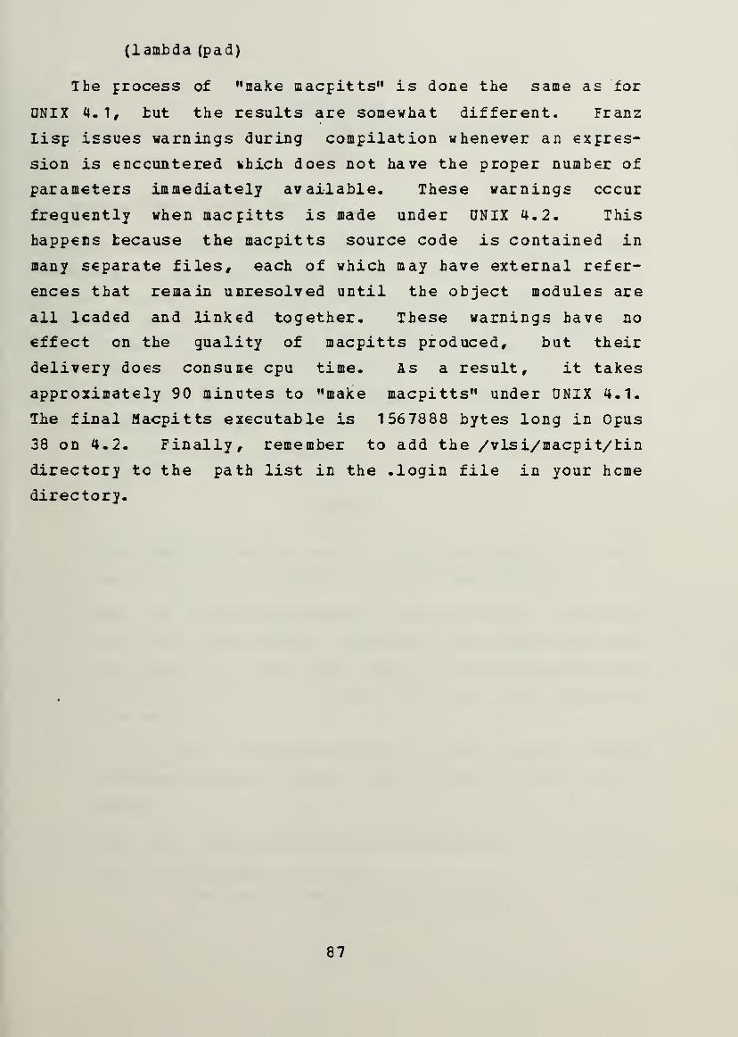
(lambda (pad)
The process of "aake macpitts" is done the same as for
UNIX 4.1, tut the results are somewhat different. Franz
lisp issues warnings during compilation whenever an expres-
sion is encountered ihich does not have the proper number of
parameters immediately available. These warnings occur
frequently when macpitts is made under UNIX 4.2. This
happens because the macpitts source code is contained in
many separate files, each of which may have external refer-
ences that remain unresolved until the object modules are
all leaded and linked together. These warnings have no
effect on the quality of macpitts produced, but their
delivery does consume cpu time. As a result, it takes
approximately 90 minutes to "make macpitts" under UNIX 4.1.
The final Macpitts executable is 1567888 bytes long in Opus
38 on 4.2. Finally, remember to add the /vlsi/macpit/tin
directory to the path list in the .login file in your heme
directory.
87


APPENDIX B
INSTAILATICN OF THE CAESAH VLSI EDITOR DNDEE UNIX 4.1 AND
4.2
A. IHSIAIIATION UNDEB UNIX 4.
1
The caesar VLSI circuit editor is one of many programs
contained in the distribution of 1983 VLSI C.A.D. tools from
0. C. Berkeley. Ihe distribution tape is loaded, in its
entirety, in the directory /vlsi/berk83 under ownership of
vlsi. Before installing the tools, perform the following:
1. Have the system programmers create a new user,
"sleeper," with password "caesar," and home directory
/vlsi/berk83/bin. Create a ".login" file in /vlsi/
berk83/bin which consists of only the following two
lines:
sleeper
logout
This step allows the use of a graphics tablet to posi-
tion the cursor in caesar, an important facility.
2. Have the system programmer create another new user,
"cad" with the password close-held, and home directory
/vlsi/berk83. This step resolves the many references
to ""cad" which are scatered throughout the distribu-
tion tape.
3. In the file /vlsi/berk83/man/tmac. anc replace every
occurrence of the string ~cad with the string /vlsi/
berk83.
4. Edit the file /vlsi/berk83/lib/displays tc contain
only the following one line:
/dev/tty22 /dev/tty20 std AED767
88

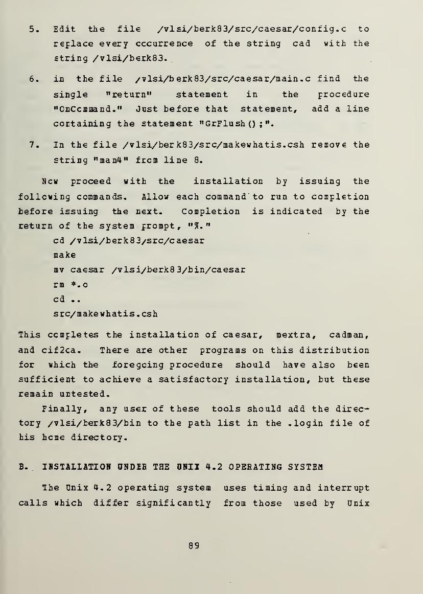
5. Edit the file /vlsi/berk83/src/caesar/config.c to
replace every occurrence of the string cad with the
string /vlsi/berk83.
6. in the file /vlsi/berk83/src/caesar/main.c find the
single "return" statement in the procedure
"CnCcmmand." Just before that statement, add a line
cortaining the statement "GrFlush () ; ".
7. In the file /vlsi/ber k83/src/makewhatis.csh remove the
string "man4" from line 8.
New proceed with the installation by issuing the
following commands. Allow each command to run to completion
before issuing the next- Completion is indicated by the
return of the system prompt, "5?."
cd /vlsi/berk8 3/src/caesar
make
mv caesar /vlsi/berk8 3/bin/caesar
rm *.o
cd -
.
src/makewhatis.csh
This completes the installation of caesar, mextra, cadman,
and cif2ca. There are other programs on this distribution
for which the foregoing procedure should have also been
sufficient to achieve a satisfactory installation, but these
remain untested.
Finally, any user of these tools should add the direc-
tory /vlsi/berk83/bin to the path list in the .login file of
his heme directory.
B. INSTALLATION UNDEE THE UNII 4.2 OPERATING SYSTEM
The Unix 4.2 operating system uses timing and interrupt
calls which differ significantly from those used by Unix
89


4.1. Therefore, because caesar makes extensive use of these
calls, the tool as installed for 4.1 will not run under 4.2.
A different distribution tape has been written for the
Berkeley 1983 design tools under UNIX 4.2. Installation of
this distribution proceeds in the same way as the 4.1
distribution except that step 6 is unnecessary. The tug
that this step corrects has already been corrected on the
4.2 distribution tape.
It is also necessary to change a line which occurs in
five files in the directory /vlsi/berk83/src/caesar
frcm #include <time. h>
to #include <sys/time.h>
The five files affected are main. c, aed4.c, omega4.c,
ramtek4.c and vect4.c.
Now proceed with the installation by issuing the
following commands:
.cd /vlsi/berk83/src/caesar
make
mv caesar /vis i/berk8 3/bin/caesar
rm *. c
cd .
.
src/makewhatis.csh
Finally, add the directory /vlsi/berk83/bin to the path
list in the .login file in your home directory.
90


APPENDIX C
HAHOAL PAGES FOB BEBKEIEY DESIGN TOOLS
Ad online operator's manual exists for all of the VLSI
design tools in the 19 83 distribution from Berkeley.
Information on the use of any of these can be made to appear
on the terminal screen by issuing
cadman <program>
where <program> can be cadman, caesar, cif2ca, cifplot,
esim, mextra, or any of the other programs in that distribu-
tion. Cnly those pages affecting tools used in this silicon
compiler research are reproduced in this appendix.
Note that the cadman program is contained in the direc-
tory
/vlsi/berk83/bin
Therefore either include this directory in the search path
of your ".login" file or invoke cadman by the full rcoted
command:
/vl si/berk 83/bin/cadman <program>.
91


CADMAN (1) CAD Toolbox User's Manual CADMAN (1)
NAMEcadman - run off section of UNIX manual
SYNOPSIScadman [ -
] [ -t ] [ section ] title ...
DESCRIPTIONCadman is a program which prints sections of the cad manual.Section is an optional arabic section number, i.e. 3, whichmay be followed by a single letter classifier, i.e. lm indi-cating a maintenance type program in section 1. It may alsobe
v
cad'', *new", *junk*', or ^public''. If a sectionspecifier is given cadman looks in the that section of thecad manual for the given titles . If section is omitted, cad-man searches all sections of the cad manual, giving prefer-ence to commands over subroutines in system libraries, andprinting the first section it finds, if any.
If the standard output is a teletype, or if the flag - isgiven, then cadman pipes its output through ssp (l) to crushout useless blank lines, ul_(l) to create proper underlinesfor different terminals, and through more (1) to stop aftereach page on the screen. Hit a carriage return to continue,a control-D to scroll 12 more lines when the output stops.
The -t flag causes cadman to arrange for the specified sec-tion to be trof
f
' ed to the Versatec.
FILES"cad/doc/cadman/man?/*
SEE ALSOProgrammer's manual: more(l), ul(l), ssp(l), man(l), appro-pos(l)
BUGSThe manual is supposed to be reproducible either on the pho-totypesetter or on a typewriter. However, on a typewritersome information is necessarily lost.
92


CAESAR(l) CAD Toolbox User's Manual CAESAR (1)
NAMEcaesar - VLSI circuit editor
SYNOPSIScaesar [ -n -g graphics_port -t tablet_port -p path -mmonitor_type -d display_type ] [ file ]
DESCRIPTIONCaesar is an interactive system for editing VLSI circuits atthe level of mask geometries. It uses a variety of colordisplays with a bit pad as well as a standard text terminal.For a complete description and tutorial introduction, seethe user manual "Editing VLSI Circuits with Caesar" (an on-line copy is in "cad/doc/caesar . tblms)
.
Command line switches are:
-n Execute in non-interactive mode.
-g The next argument is the name of the port to use forcommunication with the graphics display. If not speci-fied, Caesar makes an educated guess based on the ter-minal from which it is being run.
-t The next argument is the name of the port to use forreading information from the graphics tablet. If notspecified, Caesar makes an educated guess (usually thegraphics port)
.
-p The next argument is a search path to be used whenopening files.
-m The next argument is the type of color monitor beingused, and is used to select the right color map for themonitor's phosphors. "std" works well for most moni-tors, "pale" is for monitors with especially pale bluephosphor.
-d The next argument is the type of display controllerbeing used. Among the display types currently under-stood are: AED512, UCB512 (the AED512 with specialBerkeley PROMs for stippling) , AED767, AED640 (anAED767 configured as 483x640 pixels), Omega440, R9400,or Vectrix.
When Caesar starts up it looks for a command file with thename ".caesar" in the home directory and processes it if itexists. Then Caesar looks for a .caesar file in the currentdirectory and reads it as a command file if it exists. The.caesar file format is described under the long commandsource.
93


CAESAR(l) CAD Toolbox User's Manual CAESAR(l)
You generally have to log in on the color terminal under thename "sleeper" (password "caesar"). This is necessary inorder for the tablet to be useable. Sleeper can be killedby typing two control-backslashes in quick succession on thecolor display keyboard (on the AED displays, control-backslash is gotten by typing control-shif t-L.
)
The four buttons on the graphics tablet puck are used in thefollowing way:
left (white) (#2)Move the box so that its fixed corner (normally lower-left) coincides with the crosshair position.
right (green) (#4)Move the box's variable corner (normally upper-right)to coincide with the crosshair position. The fixedcorner is not moved.
top (yellow) (#1)Find the cell containing the crosshair whose lower-leftcorner is closest to the crosshair. Make that cell thecurrent cell. If the button is depressed again withoutmoving the crosshair, the parent of the current cell is
made the current cell.
bottom (blue) (#3)Paint the area of the box with the mask layers under-neath the crosshair. If there are no mask layers visi-ble underneath the crosshair, erase the area of thebox.
SHORT COMMANDSShort commands are invoked by typing a single letter on thekeyboard. Valid commands are:
a Yank the information underneath the box into the yankbuffer. Only yank the mask layers present under thecrosshair (if there are no mask layers underneath thecrosshair, yank all mask layers and labels).
c Unexpand current cell (display in bounding box form)
.
d Delete paint underneath the box in the mask layersunderneath the crosshair (if there are no mask layersunderneath the crosshair, the delete labels and allmask layers)
.
e Move the box up 1 lambda.
94


CAESAR (1) CAD Toolbox User's Manual CAESAR (1)
g Toggle grid on/off.
1 Redisplay the information on both text and graphicsscreens
.
q Move the box left 1 lambda.
r Move the box down 1 lambda.
s Put back (stuff) all the information in the yank bufferat the current box location. Stuff only information inmask layers that are present underneath the crosshair(if there are no mask layers underneath the crosshair,stuff all mask layers plus labels)
.
u Undo the last change to the layout.
w Move the box right one lambda.
x Unexpand all cells that intersect the box but don'tcontain it.
z Zoom in so that the area underneath the box fills thescreen.
C Expand current cell so that its paint and children canbe seen.
X Expand all cells that intersect the box, recursively,until there are no unexpanded cells intersecting thebox.
Z Zoom out so that everything on current screen fills thearea underneath the box.
5 Move the picture so that the fixed corner of the box isin the center of the screen.
6 Move the picture so that the variable corner of the boxis in the center of the screen.
*L Redisplay the graphics and text displays.
Repeat the last long command.
LONG COMMANDSLong commands are invoked by typing a colon character (":").The cursor will appear on the bottom line of the text termi-nal. A line containing a command name and parameters shouldbe typed, terminated by return. Each line may consist ofmultiple commands separated by semi-colons (to use a colon
95


CAESAR(l) CAD Toolbox User's Manual CAESAR(l)
as part of a long command, precede it with a backslash).Short commands may be invoked in long command format bypreceding the short command letter with a single quote.Unambiguous abbreviations for command names and parametersare accepted. The commands are:
align <scale>Change crosshair alignment to <scale>. Crosshair posi-tion will be rounded off to nearest multiple of<scale>
.
array <xsize> <ysize>Make the current cell into an array with <xsize>instances in the x-direction and<ysize> instances inthe y-direction. The spacing between elements isdetermined by the box x- and y-dimensions.
array <xbot> <ybot> <xtop> <ytop>Make the current cell into an array, numbered from<xbot> to <xtop> in the x-direction and from <ybot> to<ytop> in the y-direction. The spacing between arrayelements is determined by the box x- and y-dimensions.
box <keyword> <amount>Change the box by <amount> lambda units, according to
<keyword>. If <keyword> is one of "left", "right","up", or "down", the whole box is moved the indicatedamount in the indicated direction. If <keyword> is oneof "xbot", "ybot", "xtop", or "ytop" , then one of thecoordinates of the box is adjusted by the given amount.<amount> may be either positive or negative.
button <number> <x> <y>Simulate the pressing of button <number> at the screenlocation given by <x> and <y> (in pixels). If <x> and<y> are omitted, the current crosshair position isused.
cif -sblpx <name> <scale>Write out a CIF description of the layout into file<name> (use edit cell name by default; a ".cif" exten-sion is supplied by default). <scale> indicates howmany centimicrons to use per Caesar unit (200 bydefault). The -s switch causes no silicon (paint) tobe output to the CIF file.. The -b switch causes bound-ing boxes to be drawn for unexpanded cells. The -1causes labels to be output. The -p switch causes a CIFpoint to be generated for each label. The -x switchcauses Caesar not to automatically expand all cells(they are expanded by default)
.
cload <file>
96


CAESAR (1) CAD Toolbox User's Manual CAESAR (1)
Load the colormap from <file>. The monitor type isused as default extension.
clockwise <degrees> [y]Rotate the current cell by the largest multiple of 90
<deg rees>a "y"
degrees less than or equal to <degrees>. <degdefaults to 90. If the command is followed bythen the yank buffer is rotated instead of the currentcell.
colormap <layers>Print out the red, green, and blue intensities associ-ated with <layers>.
colormap <layers> <red> <green> <blue>Set the intensities associated with <layers> to thegiven values.
copycellMake a copy of the current cell, and position it sothat its lower-left corner coincides with the lower-left corner of the box.
csave <file>Save the current colormap in <file> (the monitor typeis used as default extension)
.
deletecellDelete the current cell.
editcell <file>Edit the cell hierarchy rooted at <file>. A ".ca"extension is supplied by default. If information inthe current hierarchy has changed, you are given a
chance to write it out.
erasepaint <layers>For the area enclosed by the box, erase all paint in<layers>. If <layers> is omitted it defaults to "*1 ii
fill <direction> <layers><direction> is one of "left", "right", "up", or "down".The paint under one edge of the box (respectively, theright, left, bottom, or top edge) is sampled; every-where that the edge touches paint, the paint isextended in the given direction to the opposite side ofthe box. <layers> selects which layers to fill; ifomitted then a default of "*" is used.
f lushcellRemove the definition of the current definition frommain memory and reload it from the disk version. Any
97


CAESAR(l) CAD Toolbox User's Manual CAESAR(l)
changes to the cell since it was last. written are lost.
getcell <file>This command makes an instance of the cell in <file> (a
".ca" extension is supplied by default) and positionsthat instance at the current box location. The boxsize is changed to equal the bounding box of the cell.
gr idspacingThe grid is modified so that its spacings in x and yequal the dimensions of the box. The grid is set sothat the box falls on grid points.
gripeThe mail program is run so that comments can be sent tothe Caesar maintainer.
height <size>The box's height is set to <size>. If <size> is pre-ceded by a plus sign then the fixed corner is moved toset the correct height; otherwise the variable corneris moved. <size> defaults to 2.
identifycell <name>The current cell is tagged with the instance name givenby <name>. This feature is not currently supported inany useful fashion. <name> may not contain any whitespace.
label <name> <position>A rectangular label is placed at the box location andtagged with <name>. <name> may not contain any whitespace. <position> is one of "center", "left", "right","top", or "bottom"; it specifies where the text is tobe displayed relative to the rectangle. If omitted,<position> defaults to "top".
lyra <ruleset>The program "cad/bin/lyra is run, and is passed viapipe all the mask features within 3L of the box. Theprogram returns labels identifying design rule viola-tions, and these are added to the edit cell. If<ruleset> is specified, it is passed to Lyra with the-r switch to indicate a specific ruleset. Otherwise,the current technology is used as the ruleset.
macro <character> <command>The given long command is associated with the givencharacter, such that whenever the character is typed asa short command then the given command is executed.This overrides any existing definition for the charac-ter. To clear a macro definition, type ":macro
98


CAESAR (1) CAD Toolbox User's Manual CAESAR (1)
<character>" , and to clear all macro definitions, type
mark <markl> <mark2>The box is saved in the mark given by <markl>. <markl>must be a lower-case letter. If <mark2> is specified,the box is changed to coincide with <mark2>.
movecell <keyword>The current cell is moved in one of two ways, selectedby <keyword>. If <keyword> is "byposition" , then thecell is moved so that its lower-left corner coincideswith the lower-left corner of the box. This also hap-pens if no keyword is specified. If <keyword> is"bysize", then the cell is displaced by the size of thebox (this means that what used to be at the fixedcorner of the box will now be at the variable corner) .
paint <layers>The area underneath the box is painted in <layers>.
path <path>The string given by <path> becomes the search path usedduring file lookups. <path> consists of directorynames separated by colons or spaces. Each name shouldend in "/".
peek <layers>Display all paint underneath the box belonging to<layers>, even for unexpanded cells and their descen-dants.
popbox <mark>If <mark> is specified, then the box is replaced withthe given mark. Otherwise the box stack is popped andthe top stack element overwrites the box.
pushbox <mark>The box is pushed onto the box stack. If <mark> isspecified then it is used to overwrite the box, other-wise the box remains unchanged.
put <layers>The yank buffer information in <layers> is copied backto the box location. If <layers> is omitted, itdefaults to "SI".
quit If any cells have changed since they were last saved ondisk, the user is given a chance to write them out orabort the command. Otherwise the program returns tothe shell.
99


CAESAR (1) CAD Toolbox User's Manual CAESAR (1)
resetThe graphics display is reinitialized and the colormapis reloaded.
returnThe current subedit is left, and the containing edit isresumed.
savecell <name>If <name> is specified then the current cell is giventhat name and written to disk under the name (a ".ca"extension is supplied by default). If <file> isn'tspecified then the cell is written out to the disk filefrom which it was read.
scroll <direction> <amount> <units>The current view is moved in the indicated direction bythe indicated amount. <direction> must be one of"left", "right", "up", or "down", <amount> is a
floating-point number, and <units> is one of "screens"or "lambda". <units> defaults to "screens", and<amount> defaults to 0.5.
search <regexp>Search labels and bounding boxes underneath the box fortext matching <regexp>. See the manual entry for e_d
for a description of <regexp>. Push an entry onto thebox stack for each match. Even unexpanded cells aresearched .
sideways [y]Flip the current cell sideways (i.e. about a verticalaxis) . If the command is followed by a "y" then theyank buffer is flipped instead of the current cell.
source <filename>The given file is read, and each line is processed asone long command (no colons are necessary). Any linewhose last character is backslash is joined to the fol-lowing line.
subeditMake the current cell the edit cell, and edit it incontext.
technology <file>Load technology information from <file>. A ".tech"extension is supplied by default.
upsidedown [y]Flip the current cell upside down. If the command isfollowed by a "y" then the yank buffer is flipped
100


CAESAR(l) CAD Toolbox User's Manual CAESAR (1)
instead of the current cell.
usage <file>Write out in <file> the names of all the files contain-ing cell definitions used anywhere in the designhierarchy.
view <mark>If <mark> is specified, set view to it, otherwise,change the view to encompass the entire edit cell.
visiblelayers <layers>Set the visible layers to include just <layers>. Pre-face <layers> with a plus or minus sign to add to orremove from the currently visible ones.
width <size>Set the box width to <size> (default is 2) . Move vari-able corner unless width is preceded by " + ", else movefixed corner.
writeallRun through interactive script to write out all cellsthat have been modified.
yank <layers>Save in the yank buffer all information underneath thebox in <layers>. <layers> defaults to "*1".
ycell <name>If <name> is specified, do the equivalent of "rgetcell<name>". Then expand current cell, yank it, delete thecell, and put back everything that was yanked. Thisflattens the hierarchy by one level.
ysave <name>Save the yank buffer contents in a cell named <name>. A".ca" extension is provided by default.
LAYERSnMOS mask layers are:
p or r
Polysilicon (red) layer.
d or gDiffusion (green) layer.
m Metal (blue) layer.
i or y
101

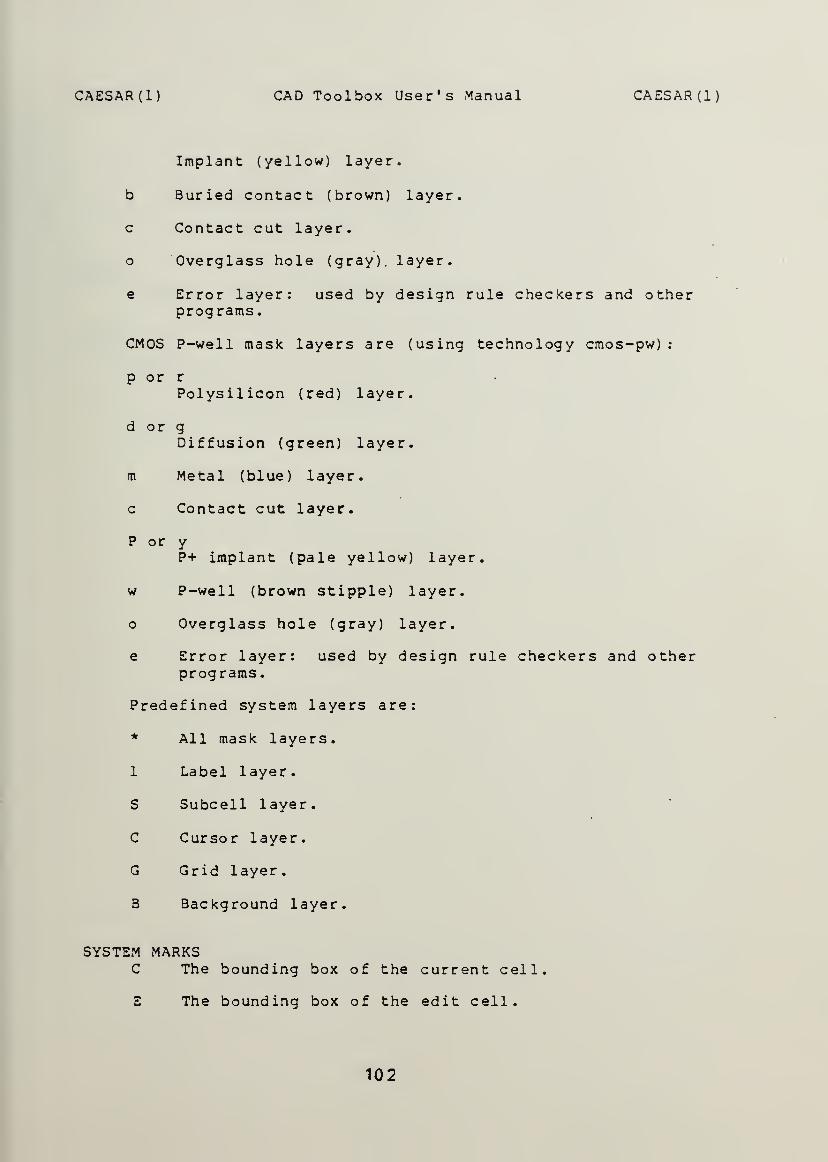
CAESAR (1) CAD Toolbox User's Manual CAESAR (1)
Implant (yellow) layer.
b Buried contact (brown) layer.
c Contact cut layer.
o Overglass hole (gray), layer.
e Error layer: used by design rule checkers and otherprograms.
CMOS P-well mask layers are (using technology cmos-pw)
:
p or r
Polysilicon (red) layer.
d or gDiffusion (green) layer.
m Metal (blue) layer.
c Contact cut layer.
P or yP+ implant (pale yellow) layer.
w P-well (brown stipple) layer.
Overglass hole (gray) layer.
e Error layer: used by design rule checkers and otherprograms.
Predefined system layers are:
* All mask layers.
1 Label layer.
S Subcell layer.
C Cursor layer.
G Grid layer.
B Background layer.
SYSTEM MARKSC The bounding box of the current cell.
E The bounding box of the edit cell.
102


CAESAR (1) CAD Toolbox User's Manual CAESAR (1)
FILES
P The previous view.
R The bounding box o£ the root cell,
V The current view.
'cad/new/caesar , "cad/doc/caesar . tblms
SEE ALSOcif 2ca(l)
103


CIF2CA(CAD) CAD Toolbox User's Manual CIF2CA(CAD)
NAMEcif2ca - convert CIF files to CAESAR files
SYNOPSIScif2ca [ -1 lambda ] [ -t tech ] [ -o offset ] ciffile
DESCRIPTIONcif 2ca accepts as input a CIF file and produces a CAESARfile for each defined symbol. Specifying the -1 lambdaoption scales the output to lambda centi-microns per lambda.The default scale is 200 centi-microns per lambda. The -ttech option causes layers from the specified technology tobe acceptable. The default technology is nmos. For a listof acceptable technologies, see caesar (1). The -o offsetoption causes all CIF numbers to be incremented by offset .
This is useful when the CIF numbers are used for Caesar filenames, and when several CIF files with overlapping numbersare to be joined together in Caesar.
Each symbol defined in the CIF file creates a CAESAR file.By default, the files are named
x
symbolm.ca''
, where m is
the CIF symbol number (as modified by the -o offset ) . Sym-bols can also be named with a user-extension " 9 '
' command,giving a name to the symbol definition which encloses it.CIF commands which appear outside of symbol definitions aregathered into a symbol called, by default, 'project'', andare output to the CAESAR file pro ject.ca
'
SEE ALSOcaesar (1)
DIAGNOSTICSDiagnostics from cif2ca are supposed to be self-explanatory.Each diagnostic g ives the line number from the input file,an error class (informational, warning, fatal, or panic),the error message, and the action taken by cif 2ca , usuallyto ignore the CIF command. Informational messages usuallyrefer to limitations of cif 2ca . Warning messages usuallyrefer to inconsistencies in the CIF file, these will typi-cally result in CAESAR files which do not accurately reflectthe input CIF file. Fatal messages refer to fatal incon-sistencies or errors in the CIF file. A fatal error ter-minates cif 2ca processing. Panic messages refer to internalproblems with cif 2ca . If any diagnostics are produced, a
summary of the diagnostics is produced.
BUGS'Delete Definitions'' commands are not implemented. ci f 2ca
also has certain restrictions due to restrictions of CAESAR:e_.g_. non-manhattan objects are not allowed.
104


CIF2CA(CAD) CAD Toolbox User's Manual CIF2CA(CAD)
Library cells are not automagically included.
Some care should be taken in naming symbols, since symbolnames are used for CAESAR file names. Names which are notunique in the first 14 characters will attempt to create thesame CAESAR file, and only the last one wins. Similarly,one should avoid trying to have two project. ca files in thesame directory.
105


CIFPLOT(CADl) CAD Toolbox User's Manual CIFPLOT (CADI)
NAMEcifplot - CIF interpreter and plotter
SYNOPSIS
cifplot [ options ]filel.cif [
file2.cif
DESCRIPTIONCifDlot takes a descriptionTCTF" ) and produces a plot,language suitable for descrAlthough CIF can be used fofor ease of discussion it wto describe integrated circany legal CIF 2.0 descriptDelete Definition commands,extensions have been addedand include files. These a
been taken to avoid any arbprograms that can be plotte
in CalCIF is
ibing i
r otherill beuit desion inc
In adto CIF,re discitraryd.
-Techa low
ntegragraphassumeigns .
ludingd i t i' o n
incluussedrestr
i
I ntermed-level gted circics appld that CCifplotsymbol
, a numbding texlater,ctions o
iate Formraph icsuit layouts,ications
,
IF is usedinterprets
renaming ander of localt on plotsCare hasn the CIF
To get a plot call cifplot withbe plotted. If the CIF descriptfiles call cifplot with the nameCifplot reads the CIF descriptioorder that they appear on the coCIF End command should be only i
plot ignores everything after thing the CIF description but befoprint a estimate of the size ofshould continue to produce a ploto abort. A typical run might 1
the name of the CIF file toion is divided among severals of all files to be used,n from the files in themmand line. Therefore then the last file since cif-e End command. After read-re plotting, cifplot willthe plot and then ask if itt. Type y to proceed and n
ook as follows:
% cifplot lib.cif sorter. cifWindow -5700 174000 -76500 168900Scale: 1 micron is 0.004075 inchesThe plot will be 0.610833 feetDo you want a plot? y
After typing y cifplot will produce a plot onVarian (11 inch Versatec) plotter.
the Benson-
Cif plot recognizes several command line options. These canbe used to change the size and scale of the plot, changedefault plot options, and to select the output device.Several options may be selected. A dash (-) must precedeeach option specifier. The following is a list of optionsthat may be included on the command line:
-w xmin xmax ymin ymax(window) The -w options specifies the window; bydefault the window is set to be large enough to containthe entire plot. The windowing commands lets you plot
106


." 'WJ '^*
CIFPLOT(CADl) CAD Toolbox User's Manual CIFPLOT (CADI
)
just a small section of your chip, enabling you to seeit in better detail. Xmin , xmax , ymin , and ymax shouldbe specified in CIF coordinates.
-s float(scale) The -s option sets the scale of the plot. Bydefault the scale is set so that the window will fillthe whole page. Float is a floating point numberspecifying the numoer of inches which represents 1
micron. A recommended size is 0.02.
-1 laver listm
(layer) Normally all layers are plotted. The -1 optionspecifies which layers NOT to plot. The layer listconsists of the layer names separated by commas, nospaces. There are some reserved names: allText, bbox,outline, text, pointName, and symbolName. Includingthe layer name allText in the list suppresses the plot-ting of text; bbox suppresses the bounding box aroundsymbols. outline suppresses the thin outline thatborders each layer. The keywords text, pointName, andsymbolName suppress the plotting of certain textcreated by local extension commands. text eliminatestext created by user extension 2. pointName eliminatestext created by user extension 94. symbolName elim-inates text created by user extension 9. allText,pointName, and symbolName may be abbreviated by at, pn,and sn repectively.
-c n_
(copies) Makes n_ copies of the plot. Works only forthe Varian and Versatec. Default is 1 copy.
-d n"(depth) This option lets you limit the amount of detailplotted in a hierarchically designed chip. It willonly instanciate the plot down n levels of calls.Sometimes too much detail can hide important featuresin a circuit.
-g n
(grid) Draw a grid over the plot with spacing every n
CIF units.
-h (half) Plot at half normal resolution. ( Not yet imple-mented . )
-e (extensions) Accept only standard CIF. User extensionsproduce warnings.
-I (non-Interactive) Do not ask for confirmation. Alwaysplot.
107


CIFPL0T(CAD1 CAD Toolbox User's Manual CIFPLOT (CADI)
-L (List) Produce a listing of the CIF file on standardoutput as it is parsed. Not recommended unless debug-ging hand-coded CIF since CIF code can be rather long.
-a
-D
-C
"(approximate) Approximate a roundflash with an jv-sidedpolygon. By default n_ equals 8. (I.e. roundflashesare approximated by octagons.) If n equals then out-put circles for roundflashes. (It is best not to usefull circles since they significantly slow down plot-ting.) ( Full ci rcles not yet implemented . )
" text "
(banner) Print the text at the top of the plot.
(Comments) Treat comments as though they were spaces.Sometimes CIF files created at other universities willhave several errors due to syntactically incorrect com-ments. (I.e. the comments may appear in the middle ofa CIF command or the comment does not end with a semi-colon.) Of course, CIF files should not have any errorsand these comment related errors must be fixed beforetransmitting the file for fabrication. But many timesfixing these errors seems to be more trouble than it is
worth, especially if you just want to get a plot. Thisoption is useful in getting rid of many of these com-ment related syntax errors.
-r (rotate) Rotate the plot 90 degrees.
-V (Varian) Send output to the varian. (This is thedefault option.
)
-W (Wide) Send output directly to the versatec. (Notavailable at NPS.)
-S (Spool) Store the output in a temporary file then dumpthe output quickly onto the Versatec. Makes nice crispplots; also takes up a lot of disk space.
-T (Terminal) Send output to the terminalimplemented.
)
(Not yet fully
-Gh
-Ga (Graphics terminal) Send output to terminal using it'sgraphics capablities. -Gh indicates that the terminalis an HP2648. -Ga indicates that the terminal is anAED 512.
-X basename(extractor) From the CIF file create a circuit
108


CIFPLOT(CADl) CAD Toolbox User's Manual CIFPLOT(CADL)
Itcir-
description suitable for switch level simulation,creates two files: basename . sim which contains thecuit description, and basename . node which contains thenode numbers and their location used in the circuitdescription.
When this option is invoked no plot is made. Thereforeit is advisable not to use any of the other optionsthat deal only with plotting. However, the window ,
layer , and approximate options are still appropriate.To get a plot of the circuit with the node numbers callcif plot again, without the -X option, and includebasename . nodes in the list of CIF files to be plotted.(This file must appear in the list of files before thefile with the CIF End command.)
-c n(copies) The -c specifies the number of copies of theplot you would like. This allows you to get many copiesof a plot with no extra computation.
-P pattern file(Pattern) The -P option lets you specify your ownlayers and stipple patterns. Pattern file may containan arbitrary number of layer descriptors. A layerdescriptor is the layer name in double quotes, followedby 8 integers. Each integer specifies 32 bits whereones are black and zeroes are white. Thus the 3
integers specify a 32 by 8 bit stipple pattern. Theintegers may be in decimal, octal, or hex. Hex numbersstart with 'Ox'; octal numbers start with '0'. The CIFsyntax requires that layer names be made up of onlyuppercase letters and digits, and not longer than fourcharacters. The following is example of a layerdescription for poly-silicon:
•NP" 0x080808080x80808080
0x040404040x40404040
0x020202020x20202020
0x010101010x10101010
-F font file(Font) The -F option indicates which font you want foryour text. The file must be in the directory' /usr/lib/vf ont ' . The default font is Roman 6 point.Obviously, this option is only useful if you have texton your plot.
-0 f ilename(Output) After parsing the CIF files, store anequivalent but easy to parse CIF description in thespecified file. This option removes the include andarray commands (see next section) and replaces themwith equivalent standard CIF statements. The resulting
109


CIFPLOT(CADl) CAD Toolbox User's Manual CIFPLOT (CADI
)
file is suitable for transmission to other facilitiesfor fabrication.
In the definition of CIF provisions were made for localextensions. All extension commands begin with a number.Part of the purpose of these extensions is to test whatfeatures would be suitable to include as part of the stan-dard language. But it is important to realize that theseextensions are not standard CIF and that many programsinterpreting CIF do not recognize them. If you use theseextensions it is advisable to create another CIF file usingthe -0 options described above before submitting your cir-cuit for fabrication. The following is a list of extensionsrecognized by cif plot .
01 filename ;
(Include) Read from the specified file as though itappeared in place of this command. Include files canbe nested up to 6 deep.
0A s m n dx dv_ ;
(Array) Repeat symbol s_ m times with d_x spacing in thex-direction and n times with dy_ spacing in the y-direction. s_, m, and n_ are unsigned integers. d_x anddy are signed integers in CIF units.
1 message ;
(Print) Print out the message on standard output whenit is read.
2" text " transform ;
2C " text " transform ;
(Text on Plot) Text is placed on the plot at the posi-tion specified by the transformation. The allowedtransformations are the same as the those allowed forthe Call command. The transformation affects only thepoint at which the beginning of the text is to appear.The text is always plotted horizontally, thus the mir-ror and rotate transformations are not really of muchuse. Normally text is placed above and to the right ofthe reference point. The 2C command centers the textabout the reference point.
9 name ;
(Name svmbol) name is associated with the current sym-bol.
94 name x_ v;
94 name x_ y_ layer ;
(Name point) name is associated with the point (x_, v) .
110


CIFPLOT(CADl) CAD Toolbox User's Manual CIFPLOT (CADI
)
Any mask geometry crossing this point is also associ-ated with name . If layer is present then just geometrycrossing tEe point on that layer is associated withname . For plotting this command is similar to text onplot. When doing circuit extraction this command isused to give an explicit name to a node. Name must nothave any spaces in it, and it should not be a number.
USE WITH MACPITTS CIFThe lines starting with user extension 0, which MacPittsplaces at the beginning of every CIF file, must either beremoved or "commented out" by enclosing them in an all-encompassing set of parentheses, thus: ( .... )
;"
.
MacPitts CIF files are usually very long. It has been foundmost convenient to run MacPitts cifplots in the backgroundwith the non-Interactive mode selected. A convenient way todo this is by using the "stipple" command:
stipple filel.cif
FILES"cad/. cadre"/.cadre"cad/bin/vdump (only in 4.1 BSD UNIX)"cad/bin/stipple/usr/lib/vfont/R.
6
/usr/tmp/#cif
*
ALSO SEEmcp(cadl), vdump(cadl), cadrc(cad5)A Guide to LSI Implementation by Hon and Sequin, Second Edi-tion (Xerox PARC, 1980) for a description of CIF.
BUGSThe -r is somewhat kludgy and does not work well with theother options. Space before semi-colons in local extensionscan cause syntax errors.
The -0 option produces simple cif with no scale factors inthe DS commands. 3ecause of this you must supply a scalefactor to some programs, such as the -1 option to cif 2ca
.
111


ESIM(CADl) CAD Toolbox User's Manual ESIM(CADl)
NAMEesim - event driven switch level simulator
SYNOPSISesim [f ilel [f ile2 ...]
]
DESCRIPTIONEsim is an event-driven switch level simulator for NMOStransistor circuits. Es im accepts commands from the user,executing each command before reading the next. Commandscome in two flavors: those which manipulate the electricalnetwork, and those to direct the simulation. Commands havethe following simple syntax:
c argl arg2 ... argn <newline>where 'c' is a single letter specifying the command to beperformed and the argi are arguments to that command. Thearguments are separated by spaces (or tabs) and the commandis terminated by a <newline>.
To run es im typeesim f ilel f ile2 . .
.
Esim will read and execute commands, first from f i 1 e
1
, thenf ile2 , etc. If one of the file names is preceded by a '-',
then that file becomes the new output file (the default out-put is stdout) . For example,
esim f.sim -f.out g.simThis would cause esim to read commands from f. sim , sendingoutput to the default output. When f. sim was exhausted,f
.
out would become the new output file, and the commands in
g. sim executed.
After all the files have been processed, and if the "q" com-mand has not terminated the simulation run, es im will acceptfurther commands from the user, prompting for each one likeso:
sim>The user can type individual commands or direct es im toanother file using the "§" command:
sim> § patchf ile.simThis command would cause es im to read commands from"patchf ile. sim" , returning to interactive input when thefile was exhausted.
It is common to have an initial network file prepared by a
node extractor with perhaps a patch file or two prepared byhand. After reading these files into the simulator, theuser would then interactively direct esim . This could beaccomplished as follows:
esim file. sim patch. 1 patch.
2
After reading the files, esim would prompt for the firstcommand. Or we could have typed:
% esim file. sim
112


ESIM (CADI) CAD Toolbox User's Manual ESIM (CADI
sira>
sim>patch.
1
patch.
2
Network Manipulation Commands
The electrical network to be simulated is made up ofenhancement and depletion mode transistors interconnected bynodes. Components can be added to the network with the fol-lowing commands:
e gate source draine gate source drain length width key xpos ypos area
Adds enhancement mode transistor to network withthe specified gate, source, and drain nodes. Thelonger form includes size and location informationas provided by the node extractor — when makingpatches the short form is usually used,
gate source draingate source drain length width key xpos ypos area
Like "e" except for depletion mode devices,nodel node2 cap
Increase the capictance between nodel and no_de_2
cap . Esim ignores this unless either nodel ornode2
d
d
by
is GND.node namel name2 name3
Allows the user to specify synonyms for a givento relate user-internal name
node. Used by the node extractorprovided node names to the node's(usually just a number)
.
comment . .
.
Lines beginning with vertical barcomments and ignored — useful for deleting piecesof network in node extractor output files.
node — output by node extractor and not
are treated as
Input recordused by es im
Currently, there is nonetwork once they have
way to remove components from thebeen added. You must go back the
input files and modify them (using the comment character) toexclude those components you wished removed. "N" recordsneed not be included for new nodes the user wishes to patchinto the network.
Simulator Commands
The user can specify which nodes are to have there valuesdisplayed after each simulation step:
w nodel -node2 node3 ...
Watch nodel and node3, stop watching node2. Atthe end of a simulation step, each watched nodewill displayed like so:
nodel=0 node3=X . .
.
To remove a node from the watched list, preface
113


ESIM(CADl) CAD Toolbox User's Manual ESIM(CADl)
its name with a '-' in a "w n command.W label nodel node2 ... noden
Watch bit vector. The values of nodes nodel, . ..,noden will displayed as a bit vector:
label=010100 20
where the first is the value of nodel, the first1 the value of node2, etc. The number displayedto right is the value of the bit vector inter-preted as a binary number; this is omitted if thevector contains an X value. There is no way tounwatch a bit vector.
Before each simulation step the user can force nodes to beeither high (1) or low (0) inputs (an input's value cannotbe changed by the simulator!):
h nodel node2 .
.
Force each node on the argument list to be a highinput. overrides previous input commands if
necessary.1 nodel node2 . .
.
Like "h" except forces nodes to be a low input.x nodel node2 . .
.
Removes nodes from whatever input list they happento be on. The next simulation step will determinetheir correct value in the circuit. This is thedefault state of most nodes. Note that this doesnot force nodes to have an "X" value — it simplyremoves them from the input lists.
The current value of a node can be determined in severalways:
vView. prints the values of all watched nodes andnodes on the high and low input lists.
? nodel node2 . .
.
Prints a synopsis of the named nodes includingtheir current values and the state of all transis-tors that affect the value of these nodes. Thisis the most common way of wondering through thenetwork in search of what went wrong...
! nodel node2 . .
.
For each node in the argument list, prints a listof transistors controlled by that node.
"?" and "I" allow the user to go both backwards and forwardsthrough the network in search of that piece causing all theproblems.
The simulator is invoked with the following commands:s
Simulation step. Propogates new values for theinputs through the network, returns when the net-work has settled. If things don't settle, commandwill never terminate — try the "w" and "D" com-mands to narrow down the problem.
114


ESIM(CADl) CAD Toolbox User's Manual ESIM(CADl)
Cycle once through the clock, as define by the K
command.I
Initialize. Circuits with state are often hard to
initialize because the initial value of each nodeis X. To cure this problem, the I command findseach node whose value is charged-X and changes it
to charged-0, then runs a simulation step. If oneiterates the I command a couple times, this oftenleads to a stable initialized condition (indicatedwhen an I command takes events, i.e., the cir-cuit is stable)
.
Try it — if circuit does not become stable in 3
or 4 tries, this command is probably of no use.
Miscellaneous Commands
toggle debug switch. useful for debugging simula-tor and/or circuit. If debug switch is on, thenduring simulation step each time a watched node is
encounted in some event, that fact is indicated tothe user along with some event info. If a nodekeeps appearing in this prinout, chances are thatits value is oscillating. Vice versa, if yourcircuit never settles (ie., it oscillates) , youcan use the "D" and "w" commands to find thenode(s) that are causing the problem.
f ilenamewrite current state of each node into specifiedfile. useful for make a break point in your simu-lation run. Only stores values so isn't reallyuseful to "dump" a run for later use — see "< n
command
.
f ilenameread from specified file, reinitializing the valueof each node as directed. Note that network mustalready exist and be identical to the network usedto create the dump file with the ">" command.These state saving commands are really provided sothat complicated initializing sequences need onlybe simulated once.
invokes network processor that finds all subnetscorresponding to simple logic gates and convertsthem into form' that allows faster simulation.Often it does the right thing, leading to a 25% to50% reduction is the time for a single step. [Weknow of one case where the transformation was nottransparent, so caveat simulee...]
115


ESIM (CADI) CAD Toolbox User's Manual ESIM (CADI)
A • • •
call extension command — provides for user exten-sions to simulator.
exit to system,
Local Extensions
V node vectorDefine a
elementSet theafter a
R n
vector of inputs for the node. The firstis initially set as the input for node .
next element of the vector as the inputcycle.
Run the simulator through n cycles. If n is notpresent make the run as long as the longest vec-tor,tors.
All watch nodes are reported hack as vec-
Clear all previously defined input vectors.K nodel vectorl node2 vector2 ... nodeN vectorN
Define the clock. Each cycle, nodes 1 through Nmust run through their respective vectors.
SEE ALSOmextra (CADI)
116


MEXTRA(CADl) CAD Toolbox User's Manual MEXTRA(CADl)
NAMEmextra - Manhattan Circuit Extractor
SYNOPSISmextra [-gho] [-u scale ] basename
DESCRIPTIONMextra reads an intergrated circuit layout description inCaltech Intermediate Form (CIF) and creates a circuitdescription. From this circuit description various electi-cal checks can be done on your circuit. The circuitdescription is directly compatible with esim , moserc , andpowest .
Names
Mextra uses the CIF label construct to implement node namesand attributes. The form of the CIF label command is asfollows
:
94 name x ^ [ layer ]
;
This command attaches the label to the mask geometry on thespecified layer crossing the point (x, y) . If no layer is
present then any geometry crossing the point is given thelabel. Mextra does not recognize the CIF user extension "0"
which is used by MIT and Lincoln Labs programs (eg. mac-pitts) to indicate node labels.
Mextra interprets these labels as node names. These namesare used to describe the extracted circuit. When no name isgiven to a node, a number is assigned to the node. A labelmay contain any ASCII character except space, tab, newline,double quote, comma, semi-colon, and parenthesis. To avoidconflict with extractor generated names, names should not benumbers or end in ' #n_' where n is a number.
A problem arises when two nodes are given the same namealthough they are not connected electrically. Sometimes wewant these nodes to have the same names, other times wedon't. This frequently happens when a name is specified ina cell which is repeated many times. For instance, if wedefine a shift register cell with the input marked 'SR.in'then when we create an 8 bit shift register we could have 8
nodes names 'SR.in'. If this happens it would appear asthough all 8 of the shift register cells were shortedtogether. To resolve this the extractor recognizes threedifferent types of names: local , global , and unspecified .
Any time a local name appears on more than one node it isappended with a unique suffix of the form ' #n ' where n is anumber. The numbers are assigned in scanline order andstarting at 0. In the shift register example, the nameswould be 'SR.in#0' through 'SR.in#7'. Global names do nothave suffixes appended to them. Thus unconnected nodes with
117


MEXTRA(CADl) CAD Toolbox User's Manual MEXTRA(CADl)
global names will appear connected after extraction. (The-g causes the extractor to append unique suffixes to uncon-nected nodes with the same global name.) Names are madelocal by ending them with a sharp sign, '#'. Names are glo-bal if they end with an exclamation mark, '!'. These ter-minating characters are not considered part of the name,however. Names which do not end with these characters are
is connected to only one node. It is illegal to have a namethat is declared two different types. The extractor willcomplain if this is so and make the name local.
Optionally mextra will expand local and unspecified nodenames with the path name of the symbol instances throughwhich they were called. By using the -h option mextra willproduce node names of the form:
/call l
/
ca!1 2 / . . .
/
callN/node-namewhere callN is the name of the symbol instance which con-tains the label node-name , callN-1 is the name of theinstance which contains call N, and so on. Named symbolinstances take the following form in CIF:
91 name ; C number [a b] ;
Unnamed CIF calls are assigned names of the form '#n', wheren is a number.
It makes no difference to the extractor if the same name isattached to the same node several times. However, if morethan one name is given to a node then the extractor mustchoose which name it will use. Whenever two names are givento the same node the extractor will assign the name with thehighest type priority, global being the highest, unspecifiednext, local lowest. If the names are the same type then theextractor takes the one with the fewest slashes ('/') ; if thenumber of slashes is equal, the shortest name is taken.This causes the name highest up in the symbol hierarchy tobe taken when hierarchical names are expanded. At the endof the log file the extractor lists nodes with more than onename attached. These lines start with an equal sign and arereadable by esim so that it will understand these aliases.
Attributes
In addtion to naming nodes mextra allows you to attachattributes to nodes. There are two types of attributes,node attributes , and transistor attributes . A node attri-bute is attached to a node using the CIF 94 construct, justthe same way as a node name. The node attribute must end inan at-sign, '
@' . More than one attribute may be attached to
a node. Mextra does not interpret these attributes other
118


MEXTRA(CADl) CAD Toolbox User's Manual MEXTRA(CADl)
than to eliminate duplicates. For each attribute attachedto a node there appears a line in the .sim file in the fol-lowing form:
A node attributeNode is the node name, and attribute is the attributeattached to that node with the at-sign removed.
Transistor attributes can be attached to the gate, source,or drain of a transistor. Transistor attributes must end in
a dollar sign, '$'. To attach an attribute to a transistorgate the label must be placed inside the transistor gateregion. To attach an attribute to a source or drain of a
transistor the label must be placed on the source or drainedge of a transistor. Transistor attributes are recorded inthe transistor record in the .sim file. A transistordescription has the following form:
type gate source drain 1 w x ^ g=attributess=attributes d=a ttr ibutes
Attributes is a comma-separated list of attributes. If noattribute is present for the gate, source, or drain the g=,s=, or d= fields may be omitted.
Capacitance
The .sim file also has information about capacitance in thecircuit. The lines containing capacitance information areof the form:
C nodel node2 cap-valuecap-value is the capacitance betweens the nodes in femto-farads. Capacitance values below a certain threshold arenot reported. The default threshold is 50 femto-f arads.
The extractor reports capacitance from two sources - capaci-tance between node and substrate, and capacitance caused bypoly overlapping diffusion but not forming a transistor.Transistor capacitances are not included since most of thetools that work on the .sim file calculate the transistorcapacitance from the width and length information.
The capacitance for each layer is calculated separately.The reported node capacitance is the total of the layercapacitances of the node. The layer capacitance is calcu-lated by taking the area of a node on that layer and multi-plying it by a constant. This is added to the product ofthe perimeter and a constant. The default constants aregiven below. Area constants are in femto-farads per squaremicron. Perimeter constants are femto-farads per micron.
layer area perimetermetal 0.03 0.0poly 0.05 0.0
119


MEXTRA(CADl) CAD Toolbox User's Manual MEXTRA(CADl)
diff 0.1 0.1poly/diff 0.4 0.0
Poly/diffusion capacitance is calculated similar to layercapacitance. The area is multiplied by constant and this isadded to the perimeter multiplied by a constant.Poly/diffusion capacitance is not threshold, however.
The -o option supresses the calculation of capacitance, andinstead, gives for each node in the circuit the area andperimeter of that node on the diffusion, poly, and metallayers. The lines containing this information look likethis:
N node dif f- area dif f-perim poly-area poly-perimmetal -area metal -per im
Node is the node name. Dif f- area through metal -per im arethe area and perimeter of the diffusion, poly, and metallayers in user defined units. (In addtion the -o optioncauses transistors with only one terminal to be recorded inthe .sim file as a transistor with source connected todrain.
)
Setting Options
By default, mextra reports locations in CIF units. A moreconvenient form of units may be specified either in the%
. cadre' file or on the command line. The form of the com-mand line option is:
units scale
To set units on the command line use the -u option.
The parameters used to compute node capacitance may bechanged by including the following commands in your ^. cadre'file.
areatocap layer valueperimtocap layer value
value is atto-farads per square micron for area, and atto-farads per micron for perimeter. layer may be "poly","diff", "metal", or "poly/diff". The threshold for report-ing capacitance may set in the
x
. cadre' file with the fol-lowing line.
capthreshold value
A negative value sets the threshold to infinity.
120


MEXTRA(CADl) CAD Toolbox User's Manual MEXTRA(CADl)
Mextra knows of two technologies, NMOS and CMOS p-well.NMOS is assumed by default. To set the technology to CMOSp-well, include the following line in your
N
. cadre 1 file:
tech cmos-pw
FILES~cad/l ib/extname"cad/lib/log"cad/. cadre"/.cadre/usr/tmp/tmext*
ALSO SEEcaesar (cadi) , kic(cadl), powest (cadi) , cadrc(cad5)
BUGSAccepts manhattan simple CIF only. The length/width ratiofor unusually shaped transistors may be inacurate. Attri-butes for funny transistors are not recorded.
121


APPENDIX D
SIBOLATION BESUITS FCB MOLTIP8C MOLTIPLIIEB
The first five figures shew, in the order that they were
produced, .int files from a MacPitts interpreter session
using the scurce file, mult ip8c. mac,
The last three figures show the terminal output produced
ly the switch level event simulation program, esim, oper-
ating en the node extraction file of the MacPitts layout for
multip8c. The node extraction was performed by the mextra
program.
n multip8c n
MacPitts interpreter state after initial data entry.
((register al undefined-(register a2 undefined-(register a3 undefined-(register a4 undefined-register hrl undefined(register lrl undefined(register hr2 undefined(register lr2 undefined(register hr3 undefined(register lr3 undefined(register hr4 undefined(register lr4 undefined(port ain 104 console)(port bin 22 console)(port hin console)(port aout undefined-in(port hout undefined-in(port lout undefined-in
integer)integer)integer)integer)-integer)-integer)-integer)-integer)-integer)-integer)-integer)-integer)
teger chip)teger chip)teger chip)
Figure D- 1 Hacpitts Interpreter Results,
122


"multip8c"MacPitts interpreter state after 1 clock cycle.
((register al 104)(register a2 undefined-integer)(register a3 undefined-integer)(register a4 undefined-integer)(register hrl 0)
(register lrl 11)(register hr2 undefined-integer)(register lr2 undefined-integer)(register hr3 undefined-integer)(register lr3 undefined-integer)(register hr4 undefined-integer)(register lr4 undefined-integer)(port ain 104 console)(port bin 22 console)(port hin console)(port aout undefined-integer chip)(port hout undefined-integer chip)(port lout undefined-integer chip)
)
"multip8c"Macpitts interpreter state after 2 clock cycles.
( ( register al 104)(register a2 104)(register a3 undefined-integer)(register a4 undefined-integer)(register hrl 0)
(register lrl 11)(register hr2 52)(register lr2 5)
(register hr3 undefined-integer)(register lr3 undefined-integer)(register hr4 undefined-integer)(register lr4 undefined-integer)(port ain 104 console)(port bin 22 console)(port hin console)(port aout undefined-integer chip)(port hout undefined-integer chip)(port lout undefined-integer chip)
)
Figure D,2 HacPitts Interpreter Results, (continued).
123


n multip8c"Macpitts interpreter state after 3 clock cycles,
( (reg(reg(reg(reg(reg(reg(reg(reg(reg(reg(reg(reg(por(por(por(por(por(por
isteristeristeristeristeristeristeristeristeristeristeristert ain
binhinaouhoulou
al 104)a2 104)a3 104)a4 undefined-integer)hrl 0)
lrl 11)hr2 52)
lr2 5)
hr3 78)lr3 2)
hr4 undefined-integer)lr4 undefined-integer)104 console)22 console)
console)t undefined-integer chip)t undefined-integer chip)t undefined-integer chip)
)
"multip8c"Macpitts interpreter state after 4 clock cycles,
( (reg(reg(reg(reg(reg(reg(reg(reg(reg(reg(reg(reg(por(por(por(por(por(por
isteristeristeristeristeristeristeristeristeristeristeristert ain
binhinaouthoutlout
al 104)a2 104)a3 104)a4 104)hrllrlhr2lr2hr3lr3hr4lr410422
0)
11)52)
5)
78)2)
39)1)
console)console)
console)104 chip)39 chip)1 chip)
)
Figure D.3 HacPitts Interpreter Results, (Continued)
12a


"multip8c"MacPitts interpreter state after 4 clock cycles and
resetting the input ports to the values of the output ports.This simulates a second chip in cascade with the first.
((register al 104)(register a2 104)(register a3 104)(register a4 104)(register hrl 0)
( register 1 rl 11
)
(register hr2 52)(register lr2 5)
(register hr3 78)(register lr3 2)
(register hr4 39)(register lr4 1)
(port ain 104 console)(port bin 1 console)(port hin 39 console)(port aout 104 chip)(port hout 39 chip)(port lout 1 chip)
)
"multip8c"Macpitts interpreter state after 5 clock cycles,
((register al 104)(register a2 104)(register a3 104)(register a4 104)(register hrl 71)(register lrl 128)(register hr2 52)(register lr2 5)
(register hr3 78)(register lr3 2)
(register hr4 39)(register lr4 1)
(port ain 104 console)(port bin 1 console)(port hin 39 console)(port aout 104 chip)(port hout 39 chip)(port lout 1 chip)
)
Figure D-4 HacPitts Interpreter Results, (Continued),
125


n multip8c n
Macpitts interpreter state after 6 clock cycles,
( (reg(reg(reg(reg(reg(reg(reg(reg(reg(reg(reg(reg(por(por(por(por(por(por
isteristeristeristeristeristeristeristeristeristeristeristert ain
binhinaout
al 104)a2 104)a3 104)a4 104)hrl 71)lrl 128)hr2 35)lr2 192)hr3 78)lr3 2)
hr4 39)lr4 1)104 console)1 console)39 console)104 chip)
hout 39 chip)lout 1 chip)
)
( (reg(reg(reg(reg(reg(reg(reg(reg(reg(reg(reg(reg(por(por(por(por(por(por
"multip8c"Macpitts interpreter state after 7 clock cycles.
ister al 104)ister a2 104)ister a3 104)ister a4 104)ister hrl 71)ister lrl 128)ister hr2 35)ister lr2 192)ister hr3 17)ister lr3 224)ister hr4 39)ister lr4 1)t ain 104 console)t bin 1 console)t hin 39 console)t aout 104 chip)t hout 39 chip)t lout 1 chip))
Figure D-5 MacPitts Interpreter Results, (Continued).
126


n multip8c"Macpitts interpreter state after 8 clock cycles.
((register al 104)(register a2 104)(register a3 104)(register a4 104)(register hrl 71)(register lrl 128)(register hr2 35)(register lr2 192)(register hr3 17)(register lr3 224)(register hr4 8)(register lr4 240)(port ain 104 console)(port bin 1 console)(port hin 39 console)(port aout 104 chip)(port hout 8 chip)(port lout 240 chip))
"multip8c"MacPitts interpreter state after 9 clock cycles,
((register al 104)(register a2 104)(register a3 104)(register a4 104)(register hrl 71)(register lrl 128)(register hr2 35)(register lr2 192)(register hr3 17)(register lr3 224)(register hr4 8)
(register lr4 240)(port ain 104 console)(port bin 1 console)(port hin 39 console)(port aout 104 chip)(port hout 8 chip)(port lout 240 chip))
Figure D„6 HacPitts Interpreter Results, (Continued)
127


% esim mul8c.sim mul8c. macro1612 transistors, 1393 nodes (801 pulled up!1612 transistors, 1398 nodes (801 pulled up)sim> s
step took 605 eventsclock=XXXaout=XXXXXXXXlout=XXXXXXXXhout=XXXXXXXXhin=00000000bin=00010110 22ain=01101000 104sim> I
initialization took 2119 stepssim> I
initialization took stepssim> sstep took eventsclock=000aout'llllllll 255lout=llllllll 255hout=llllllll 255hin=00000000bin=00010110 22ain=01101000 104sim> cclock=101 5
aout=llllllll 255lout=01111111 127hout=01111111 127hin=00000000bin=00010110 22ain=01101000 104cycle took 1433 eventssim> cclock=101 5
aout=llllllll 255lout=00111111 63hout=00111111 63hin=00000000bin=00010110 22ain=01101000 104cycle took 1210 events
Last line is repeated at top of following page.
Figure D.7 Event Siaulation Results.
128


— -- -1
cycle took 1210 eventssim> cclock=101 5
aout=llllllll 255lout-00011111 31hout=00011111 31
hin=00000000bin=00010110 22ain=01101000 104cycle took 1231 eventssim> cclock=101 5
aout=01101000 104lout=00000001 1
hout=00100111 39hin=00000000bin=00010110 22ain=01101000 104cycle took 1139 eventssim> cclock=101 5
aout=01101000 104lout=00000001 1
\
hout=00100111 39
hin=00000000bin=00010110 22ain=01101000 104cycle took 1052 events
sim> a mul8c.macro2sim> s
step took 177 eventsclock=101 5
aout=01101000 104lout=00000001 1
hout=00100111 39hin=00100111 39bin=00000001 1
ain=01101000 104sim> c
Last line is repeated at top of following page.
Figure E-3 Event Simulation Results, (Continued)
129


sim> c
clock=101 5
aout=01101000 104lout=00000001 1
hout=00100111 39hin=00100111 39bin=00000001 1
ain=01101000 104cycle took 1164 eventssim> cclock=101 5
aout=01101000 104lout=00000001 1
hout=00100111 39hin=00100111 39bin=00000001 1
ain=01101000 104cycle took 1154 eventssim> c
clock=101 5
aout=01101000 104lout=00000001 1
hout=00100111 39hin=00100111 39
bin=00000001 1
ain=01101000 104cycle took 1131 eventssim> c
clock=l01 5aout=01101000 104lout=11110000 240hout=00001000 8
hin=00100111 39bin=00000001 1
ain=01101000 104cycle took 1123 eventssim> c
clock=101 5
aout=01101000 104lout=11110000 240hout=00001000 8
hin=00100111 39
bin=00000001 1
ain=01101000 104cycle took 1052 eventssim> q%
Figure D.9 Event Simulation Results, (Continued)
.
130


APPENDIX E
LAYOUT PHOTOGRAPHS
Exposure data:
Display: AID 767 Color Graphics TermiEal
Wester Light Value: 7.5 to 8.5
Camera: Pentax SLR, Tripod Mounted
Film: Tri-X, ASA 400
Lens-to-screen distance: 4 feet
Lens: 85 mm, f1.9
Lens Opening: f16
Shutter Speed: 1 second
131


vSyi;*:-:^^
Figure E. 1 aultic (top) , multip (bot)
132


fgH i
*!+jfil* >J*J*jfj*J+jt
111nrrrrffl
«#,---»* g-m -> ^-ac -y****
J
i^iPii^iiN^
*..^i>^::S:^% :'5^>%;:>^:
Figure E.2 iultip8 (top), multip8a (bot)
133


Wfk.Mfaffcifiif&
I
m » * m m-m m s a m.nmm
Figure E.3 aultip8b (top) , multip8c5 (bot)
134


mffimW- »*•»»»»*.»**.»*vm7rmff^////m7//'7.''':^w^ r"''' ;
- mm BBHsaRSRBHww!'" >?•>>•.wV.^vw.-.v.vv-.-
Figure E- 4 ultip8c4 (top), aultip8c4d (hot)
135


Figure E.5 Layout Errors in Jcchip2.
136


IIST OF REFERENCES
1. Conradi, J- R. and Hauenstein, B. R. - V LSI Design of aVery Fas t Pipelined C arr y Look Ahead IdcTer , """Master'sTresis, TTavai "PcsrfraHuate schooTT Sep^TemrTer 1983.
2. Mead, C. and Conway. 1. , Introductio n to VLSI Sys tems ,
Addison- Wesley , 1980.
3. Southard f J, R., "MacPItts: An Approach to SiliconCompilation." Compute r, v. 16, pp. 74-82, December19 63.
4. Siskind, J. M, Southard, J. R. and Crouch, K. W.
,
"Generating Custom High Performance VLSI designs fromSuccinct Algorithmic Descriptions," Proceedin gs ,
Confe rence on A dvanced R esearch in VLS I, ""pp. ~2"8-4TJ,"mi7
5. Wallich, P., "Cn the Horizon: Fast Chips Quickly,"IEEE Spectrum , v. 21, pp. 28-34, March 1984.
6. Computer Science Division, Department of ElectricalEngineering and Computer Sciences, University ofCalifornia, Eerkeley, Editing VLSI Circuits W ithCaesar, by J. Custerhout, pp.~T="2l, HarcE"~227 1983.
7. Werner, J., "The Silicon Compiler: Panacea, WishfulThinking, or Old Hat?" VLSI Design, v. 3, pp. 4 6-52,Septenber/Octorer 1982.
8. The Microelectronics Center of North CarolinaTechnical Report 83-0 6, Silicon Compilers : A CriticalSurvey* by R. R. Gross, 3l May 1T83T~
9. Herner, J., "Progress Toward the 'Ideal 1 SiliconCompiler, Part II: the layout Problem," VLSI Design,v. 4, pp. 78-81, October 1983.
10. Johansen, D. , "Bristle Blocks: A Silicon Compiler,"Sixteenth Design Aut omation Conferenc e Proceed ings ,
p~lT0=:3137~TrFE C^pufe£~SocreTy7~TT79.
11. Bergman, N. , "A Case Study of the F. I. R. S. T.Silicon Compiler," P roceeding s, Third Ca lTechConfe rence on VISI, Pasadena, calif.," pp. 4T3-4JU,Harcl~T9'H3."
12. Ayres, R. F. , VLSI : Silicon Compilat ion and the Artof Au tomatic Microchip flesign, pp. j-5, Pra nTTce-lall,I 3 CO *
137


13. University of California at Berkeley. Tha Franz LispManual, by J. K. Foderaro, K. L. 5klower,~ancI Kevinlayer, June 1983.
14. Lincoln Laboratory, Massachusetts Institute ofTechnology Project Report RVLSI-5, L5 U ser s G uid e, byK. I. Crouch, p. 19, 7 March 1984.
15. Weinberger, A., "Large Scale Integration of MOSComplex Logic: A Layout Method," IEEE Journal ofSolid State Circuits, v. sc-2, pp. TFZ^^U DecemberT9F7T
**
16. Lincoln Laboratory, Massachusetts Institute ofTechnology Project Report RVLSI-3, An Introduction toMacEitts, by J. R. Southard, 10 February T9U3.
17. Locmis, H. Jr. and Sinha, B., "High Speed RecursiveDigital Filter Realization," pre-print of a paper toappear in Circuits, Systems ana Signal Processing.
18. Rung, H. 1. and Leiserson, C. E. , "Systolic Arrays(for VLSI! ," Sparse M atr ix Proceedings, 1978, Societyfor Industrial ancPAppned" Mathematics, pp. 256-282,1979.
19. Kelly, G. I. v A Custom Integrated Circuit forC onnecting Multiple "Processing Element s ~ Using alasel ine N etwo rTTT^ paper presented at the SeventeenthInnuaTTsiiomar" Conference on Circuits and Systems,Pacific Grove, California, 1 November 1983.
20. Newkirk, J. A. and Mathews, R., The VLS I D esi gner'sLibrary, Addiscn-Wesley, 1983.
138


BIB1I0GBAPHY
Bourne, £- R-, The UNIX Sys tem, Addison-Wesley, 1983.
Feldman, J. A- and Beauchemin, E. J., "A Custom IC forAutomatic Gain Control in IPC Vocoders," Proceedings ofICASSP J.83, Boston, Bass, April 1983-
"
Fox, J. E- 4 "The MacPItts Silicon Compiler: A View From theTelecommunications Industry," VLS I Design, v. 4, May/June1983 •
Bwanq, K-, Com pute r Arithme tic : Principles, Architecture ,
and Design, wiiey,~1S'?9.
Kogge, P. M-, The Arch itecture of Pipeline d Computers,Eemisphere, 1981.
Srini, V. P., "Test Generations from MacPitts Designs,"Procee dings of the Inter nations Conference on Com puter^esicjnT NovemBer T7B3-
Wallich, P., "Technology *83: Automation(Design/Manufacturing)," IEEE Spectru m, v. 20, January 1983.
Werner, J- , "Progress Toward the •Ideal* Silicon Compiler,Part I: the Front End," VLSI Design, v. 4, September 1983.
Hinstcn, P- H. and Berthold, K. P- H. , LISP, Addison-Wesley,198 1.
139


INITIAL DISTRIBUTION LIST
No. Copies
1. Superintendent 2Attn: Library, Code 142Naval Postgraduate SchoolMonterey, CA 93943
2. Er. Donald Kirk 5Code 62KINaval Postgraduate SchoolMonterey, CA 93943
3. Prof. Robert Strum 1
Cod€ 62STNaval Postgraduate SchoolMonterey, CA 93943
4- Er. H- H. Loomis 1
Code 6 2LMNaval Postgraudate SchoolMonterey, CA 93943
5. Mr. Albert Hong 1
Code 52 *Naval Postgraduate SchoolMonterey, CA 93943
6. Chairman, ECE Department 1
Code 62Naval Postgraduate SchoolMonterey, CA 93943
7. ICDR Dennis J. Carlson 1
Fleet Air Reconnaissance Squadron ThreeFPO San Francisco, CA 96601
8. IT Joseph R. Corradi 1
5293 Iroquois AvenueFwa Beach, HI S6706
9. Defense Technical Information Center 2Cameron StationAlexandria, VA 22314
10. Er. Gerry L. Kelly 1
Department of ECIUniversity of KaEsasLawrence, Kansas 66045
11. Mr. A. E. Hastings 1
Dept. 81-60, Bldg. 157Lockheed Missle and Space CompanyP. C. Eox 504Sunnyvale, CA 94086
12. Mr. G. S. Ogden 1
Eept. 81-6 1, Bldg. 157lockheed Missle and Space CompanyP. C. Eox 5 04Sunnyvale, CA 940 86
140


13- Er. Antun Domic, B-347Massachusetts Institute of Technologylinccln LaboratoryE.O. Eox 73Lexington, HA 02173-0 073
14. Mr. Peter BlankecshipMassachusetts Institute of Technologylinccln LaboratoryE.O. Ecx 73Lexington, MA 02173-0 073
141


"Application of a sili-
con compiler to VLSI
design of digital pipe-
lined multipliers.
S KW 90326X6
2C829G
ThesisC2328c.l
CarlsonApplication of a sili-
con compiler to VLSIdesign of digital pipe-lined multipliers.
w