Core Network Design for IPTV Transport - Cisco 01, 2008 · Core Network Design for IPTV Transport...
41
© 2008 Cisco Systems, Inc. All rights reserved. Cisco Confidential Presentation_ID 1 Core Network Design for IPTV Transport John Evans, Distinguished Consulting Engineer [email protected]
Transcript of Core Network Design for IPTV Transport - Cisco 01, 2008 · Core Network Design for IPTV Transport...
© 2008 Cisco Systems, Inc. All rights reserved. Cisco ConfidentialPresentation_ID 1
Core Network Design for IPTV Transport
John Evans, Distinguished Consulting Engineer
© 2008 Cisco Systems, Inc. All rights reserved. Cisco ConfidentialPresentation_ID 2
Core Network Design for IPTV Transport
� Reference Architecture
� IP Transport Options
� Video SLA Requirements
� Unicast Routing Protocol Design
� Multicast Architecture
� Resiliency
� QOS Architecture
� VQE
� Service Management and Monitoring
© 2008 Cisco Systems, Inc. All rights reserved. Cisco ConfidentialPresentation_ID 3
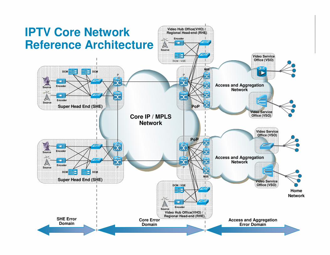
IPTV Core NetworkReference Architecture
Access and AggregationNetwork
Access and AggregationNetwork
Core IP / MPLSNetwork
HomeNetwork
PoPSuper Head End (SHE)
Video ServiceOffice (VSO)
DCM
EncoderSource
DCM / VQE
MSE
MSE
Video ServiceOffice (VSO)
Video ServiceOffice (VSO)
Video ServiceOffice (VSO)
EncoderSource
DCM
Super Head End (SHE)
DCM
EncoderSource
EncoderSource
DCM
Encoder
Source
Video Hub Office(VHO) /Regional Head-end (RHE)
PoP
DCM / VQE
EncoderSource
Video Hub Office(VHO) /Regional Head-end (RHE)
P P
PP
SHE ErrorDomain
Core ErrorDomain
Access and AggregationError Domain
© 2008 Cisco Systems, Inc. All rights reserved. Cisco ConfidentialPresentation_ID 4
IPTV Core NetworkReference Architecture
Access and AggregationNetwork
Access and AggregationNetwork
Core IP / MPLSNetwork
HomeNetwork
PoPSuper Head End (SHE)
Video ServiceOffice (VSO)
DCM
EncoderSource
DCM / VQE
MSE
MSE
Video ServiceOffice (VSO)
Video ServiceOffice (VSO)
Video ServiceOffice (VSO)
EncoderSource
DCM
Super Head End (SHE)
DCM
EncoderSource
EncoderSource
DCM
Encoder
Source
Video Hub Office(VHO) /Regional Head-end (RHE)
PoP
DCM / VQE
EncoderSource
Video Hub Office(VHO) /Regional Head-end (RHE)
P P
PP
SHE ErrorDomain
Core ErrorDomain
Access and AggregationError Domain
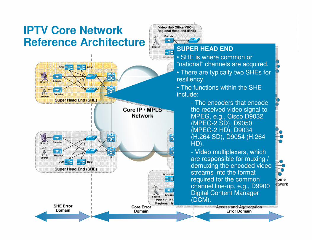
SUPER HEAD END
• SHE is where common or “national” channels are acquired.
• There are typically two SHEs for resiliency.
• The functions within the SHE include:
- The encoders that encode the received video signal to MPEG, e.g., Cisco D9032 (MPEG-2 SD), D9050 (MPEG-2 HD), D9034 (H.264 SD), D9054 (H.264 HD).
- Video multiplexers, which are responsible for muxing / demuxing the encoded video streams into the format required for the common channel line-up, e.g., D9900 Digital Content Manager (DCM).
© 2008 Cisco Systems, Inc. All rights reserved. Cisco ConfidentialPresentation_ID 5
IPTV Core NetworkReference Architecture
Access and AggregationNetwork
Access and AggregationNetwork
Core IP / MPLSNetwork
HomeNetwork
PoPSuper Head End (SHE)
Video ServiceOffice (VSO)
DCM
EncoderSource
DCM / VQE
MSE
MSE
Video ServiceOffice (VSO)
Video ServiceOffice (VSO)
Video ServiceOffice (VSO)
EncoderSource
DCM
Super Head End (SHE)
DCM
EncoderSource
EncoderSource
DCM
Encoder
Source
Video Hub Office(VHO) /Regional Head-end (RHE)
PoP
DCM / VQE
EncoderSource
Video Hub Office(VHO) /Regional Head-end (RHE)
P P
PP
SHE ErrorDomain
Core ErrorDomain
Access and AggregationError Domain
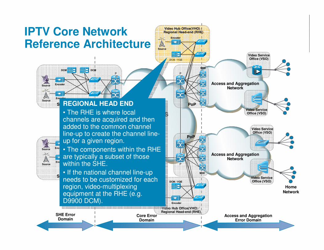
REGIONAL HEAD END
• The RHE is where local channels are acquired and then added to the common channel line-up to create the channel line-up for a given region.
• The components within the RHE are typically a subset of those within the SHE.
• If the national channel line-up needs to be customized for each region, video-multiplexing equipment at the RHE (e.g. D9900 DCM).

© 2008 Cisco Systems, Inc. All rights reserved. Cisco ConfidentialPresentation_ID 6
IPTV Core NetworkReference Architecture
Access and AggregationNetwork
Access and AggregationNetwork
Core IP / MPLSNetwork
HomeNetwork
PoPSuper Head End (SHE)
Video ServiceOffice (VSO)
DCM
EncoderSource
DCM / VQE
MSE
MSE
Video ServiceOffice (VSO)
Video ServiceOffice (VSO)
Video ServiceOffice (VSO)
EncoderSource
DCM
Super Head End (SHE)
DCM
EncoderSource
EncoderSource
DCM
Encoder
Source
Video Hub Office(VHO) /Regional Head-end (RHE)
PoP
DCM / VQE
EncoderSource
Video Hub Office(VHO) /Regional Head-end (RHE)
P P
PP
SHE ErrorDomain
Core ErrorDomain
Access and AggregationError Domain
VIDEO HUB OFFICE (VHO)
• Where most of the distributed video application components reside.
• Many video application components have a centralized component (e.g., CDS Vault) and a distributed component (e.g., CDS streamer)
• The VHO is typically located at the boundary between the core and access/aggregation networks

© 2008 Cisco Systems, Inc. All rights reserved. Cisco ConfidentialPresentation_ID 7
IPTV Core NetworkReference Architecture
Access and AggregationNetwork
Access and AggregationNetwork
Core IP / MPLSNetwork
HomeNetwork
PoPSuper Head End (SHE)
Video ServiceOffice (VSO)
DCM
EncoderSource
DCM / VQE
MSE
MSE
Video ServiceOffice (VSO)
Video ServiceOffice (VSO)
Video ServiceOffice (VSO)
EncoderSource
DCM
Super Head End (SHE)
DCM
EncoderSource
EncoderSource
DCM
Encoder
Source
Video Hub Office(VHO) /Regional Head-end (RHE)
PoP
DCM / VQE
EncoderSource
Video Hub Office(VHO) /Regional Head-end (RHE)
P P
PP
SHE ErrorDomain
Core ErrorDomain
Access and AggregationError Domain
VIDEO SERVICE OFFICE (VSO)
• Where the aggregation nodes (and sometimes access nodes) are typically located.
• The VSO is typically the closest provider-owned facility to the subscriber, e.g., the central office or local exchange.
• This may be where the Cisco Visual Quality of Experience (VQE) capability may
•be located.
POINT OF PRESENCE (POP)
• Where the termination devices for IP services are located.
POINT OF PRESENCE (POP)
• Where the termination devices for IP services are located.

© 2008 Cisco Systems, Inc. All rights reserved. Cisco ConfidentialPresentation_ID 8
Core Video Transport:Primary Technology challenges
� The Primary Technology and Competitive Market Challenges:
1. Basic transport
How to shift the packets … IP or MPLS, native or VPN?
2. Video service SLA
How to ensure that the IP network delivers the required SLAs
3. Service Monitoring and Management
How to verify that the IP network is delivering the required SLAs for video, and to identify problem areas

© 2008 Cisco Systems, Inc. All rights reserved. Cisco ConfidentialPresentation_ID 9
p2mp Transport Options
� IP1) Native
2) mVPN, i.e. mGRE
� LSM3) p2mp TE global *
MLDP
4) MLDP global **
5) MLDP ** + mVPN
* LSP scalability issues make TE a non starter for bidirectional (mp2mp) mVPN
** Can be used a) without TE FRR or b) in conjunction with TE FRR
1) IP
MPLS(LSM)
Multicast
5) mVPN4) MLDP **
3) p2mp TE *
2) mVPN (mGRE)

© 2008 Cisco Systems, Inc. All rights reserved. Cisco ConfidentialPresentation_ID 10
Service Requirements Summary
NoNoYes(time limited reservations)
Admission control and Admission control and bwbwreservationreservation
mp2mpp2mpp2mpp2mp or mp2mp?p2mp or mp2mp?
YesPossibly – for wholesale services
NomVPNmVPN requirementrequirement
NoNoYesOffload routingOffload routing
YesYesYesPath diversityPath diversity
YesYesYesFRR or equivalentFRR or equivalent
MDT is dynamic; joins and leaves may impact core
Static trees100s of new trees per day; trees static once
established
MDT dynamismMDT dynamism
100s of sites; potentially 1000s
Millions<10Receivers per GReceivers per G
100s (S, G) per VPN; 100s of VPNs
#(S, G) < 1000#(S, G) < 1000#(S, G)#(S, G)
1 or 21 or 21 or 2#S per G#S per G
SM and SSMSSM onlySSM onlyPIM modePIM mode
Managed Managed Enterprise Enterprise mVPNmVPN
Video Secondary Video Secondary DistributionDistribution
Video ContributionVideo Contribution

© 2008 Cisco Systems, Inc. All rights reserved. Cisco ConfidentialPresentation_ID 11
IP / MPLS p2mp technology choices
Enterprise VPNContributionSecondary Distribution
Typical Typical ApplicationApplication
������������Scalable mp2mp Scalable mp2mp MVPNMVPN
������������(RSVP)
Admission Admission control and control and bwbwreservationreservation
����(MoFRR or MTR)
��������(MoFRR or MTR)
Path separationPath separation
����(IGP metric based traffic engineering)
��������(IGP metric based traffic engineering)
Offload routingOffload routing
< ~1s(~50ms with p2p
MPLS TE FRR LP)
~50ms(link failures only)
< ~1s(link and node failures)
ConvergenceConvergence
mLDPmLDPp2mp MPLS TEp2mp MPLS TEPlain IP Plain IP MulticastMulticast
CharacteristicCharacteristic

© 2008 Cisco Systems, Inc. All rights reserved. Cisco ConfidentialPresentation_ID 12
Availability targets of 99.999%Resilient network topology, Resilient sources,Carrier class platforms
One-way end-to-end delays <<100ms
Deploy Diffserv IP QOS
Minimise packet loss
Fast Routing Protocol Convergence,Anycast source,Cisco VQE
Video SLA Requirements
SLA Requirements Network Design Solution

© 2008 Cisco Systems, Inc. All rights reserved. Cisco ConfidentialPresentation_ID 13
Unicast Routing Design
� The Interior Gateway routing Protocol (IGP) can be OSPF or ISIS
� It is recommended that a single IGP area/level be used within the core
� It is recommended that routes to the multicast sources be carried in the IGP
There is no benefit in carrying routes to the source in BGP
� It is recommended that fast routing protocol convergence is used

© 2008 Cisco Systems, Inc. All rights reserved. Cisco ConfidentialPresentation_ID 14
Multicast Routing Design
� PIM-SSM is recommended as the multicast routing protocol
� Source Specific Multicast (SSM)
SSM [RFC4607] is the IP multicast model used where the receiver (or some proxy) sends (S,G) joins rather than (*,G) joins, to indicate that it wants to receive traffic sent by a specific source S to a group G
� Any Source Multicast (ASM)
By contrast to SSM, in the Any Source Multicast (ASM) model, a receiver expresses interest in all traffic destined to a multicast group G, hence the multicast network must discover all multicast sources sending to that address and forward data from all sources to all interested receivers

© 2008 Cisco Systems, Inc. All rights reserved. Cisco ConfidentialPresentation_ID 15
Multicast Routing Design
Source Specific Multicast (SSM)
� With SSM, the network builds a separate distribution tree for each multicast source and clients immediately receive content directly from the source
� PIM-SSM is the subset of PIM-SM [RFC 4601] used to create (S,G) trees
� There is no shared tree (*,G) state, nor Rendezvous Points in SSM.
� SSM requires that multicast receivers explicitly specify a source address in multicast group join requests, e.g., which can be supported with IGMPv3 or through mapping IGMPv2 join requests to specific sources.

© 2008 Cisco Systems, Inc. All rights reserved. Cisco ConfidentialPresentation_ID 16
Multicast Routing Design
Why Source Specific Multicast (SSM)?
� SSM offers benefits over ASM for one-to-many dissemination-style applications, such as IPTV with one or more senders whose identities are known before the application sessions start:
1. Simplification. SSM relieves the network of needing to discover where multicast sources are present and removes the need for RPs
2. Security. SSM is considered more secure than ASM, because the multicast clients must know both the multicast group and source addresses in order to join the group. Further, other devices acting as sources transmitting to the same multicast group are not able to interfere with the service, which could happen with ASM.
3. Scalability. SSM offers better scalability
a) SSM can reduce the amount of multicast state information that the network must maintain
b) SSM improves scaling for multicast group addressing as the totalnumber of group addresses are effectively multiplied by the total number of usable source IP addresses in the provider’s network.

© 2008 Cisco Systems, Inc. All rights reserved. Cisco ConfidentialPresentation_ID 17
IP Video Service Optimization:Multicast Traffic Replication
� Provide TV quality video services over a converged IP core network
� Innovative Service Intelligent Fabrics built for massive video traffic (multicast) replication and forwarding
� Superior In-fabric replication (compared to inefficient ingress card replication in competitors)
Unicast Packet Multicast Packet
CRS-1 Multi-Chassis
XR12000ASR9000
7600
Interface
Interface
Interface
Interface
Interface
Ingress Card Egress CardFabric
Wire-rate multicast with
efficient replication

© 2008 Cisco Systems, Inc. All rights reserved. Cisco ConfidentialPresentation_ID 18
Resiliency
Core network link or node failures.
� The core network is built resiliently with no single points of failure, so that on the failure of any single component (link or node) between the head-end and the receivers, an alternate path will be available.
� On the failure of a core link or node, there will be a loss in connectivity until the IGP reconverges on the alternate path.
� Unicast and multicast fast convergence are used to minimise the loss of connectivity

© 2008 Cisco Systems, Inc. All rights reserved. Cisco ConfidentialPresentation_ID 19
Fast IP Routing Protocol Convergence
� Fast IP routing protocol convergence reduces the loss of connectivity following network (link and node) failure cases
� Multicast convergence is dependent upon unicast convergence due to the requirements of the Reverse Path Forwarding (RPF) check by the multicast control plane to build the source tree.
� Therefore, fast unicast convergence is a prerequisite for fast multicast convergence.
� Implementation and protocol optimisations that can deliver sub second convergence times for unicast (OSPF, ISIS, BGP) [FRANCOIS] and multicast

© 2008 Cisco Systems, Inc. All rights reserved. Cisco ConfidentialPresentation_ID 20
Multicast (SSM) Fast Convergence (CRS-1)Convergence Time for All Channels Following a Network Failure
0
200
400
600
800
1000
400 800 4000
Number of IPTV Channels
Reco
nverg
en
ce (
ms) Median of Median
Max of Max
No more than one I-frame loss even in the worst case
Tested with 2500 IGP prefixes and 250k BGP routesImpact of multicast convergence on unicast convergence is negligible
Prefix prioritisation allows important groups (e.g. premium channels) to converge first
Prefix prioritisation allows important groups (e.g. premium channels) to converge first

© 2008 Cisco Systems, Inc. All rights reserved. Cisco ConfidentialPresentation_ID 21
Resiliency
Source failure:
� Multiple active sources are used for resiliency
� On failure of the active source, anycast (or “priority cast”) source is used in order to switch to the alternate source
� Anycast relies upon each source using the same (S, G) for the same channel; each receiver joins to the topologically closest source for that group.
On the failure of one source or the link connecting to it, the subnet will no longer be available and the network will reconverge on the working source.
� With “priority cast”, each receiver joins with the highest priority DCM for that group, where the priority is influenced either by using different prefix lengths or by engineering IGP metrics.

© 2008 Cisco Systems, Inc. All rights reserved. Cisco ConfidentialPresentation_ID 22
Anycast Source
(S1, G1)
IGMP Report
PIMjoin
I will send jointo the nearest
S1
IGMP Report
I will send jointo the nearest
S1
STB STB
(S1, G1)
PIMjoin

© 2008 Cisco Systems, Inc. All rights reserved. Cisco ConfidentialPresentation_ID 23
Anycast Source
(S1, G1)
IGMP Report
I will send jointo the nearest
S1
IGMP Report
STB STB
(S1, G1)
XX

© 2008 Cisco Systems, Inc. All rights reserved. Cisco ConfidentialPresentation_ID 24
QOS Design
� Diffserv IP QOS mechanisms are used to control queuing delays and ensure that video control messages and MPEG packets are not dropped
� Diffserv allows us to support multiple classes of traffic with different under-or over-provisioning ratios, hence SLAs, per class of service
� Provides isolation between services – mitigating the risk associated with failures when supporting differential services
� With an appropriate QOS design and capacity planning, the only network events that should result in a visual impairment to the video service are packet losses due to lower-layer errors or network element failures
� Key design considerations
How many classes are needed?
What marking scheme to use?
Scheduler configuration

© 2008 Cisco Systems, Inc. All rights reserved. Cisco ConfidentialPresentation_ID 25
Core Classes – How many is enough?
� At the network edge different classes are used for both SLA differentiation and for application isolation
� In the core, typically where traffic is aggregated, supporting the QoS requirements for a class can effectively be translated into a problem of bandwidth provisioning
Different classes are used for SLA differentiation and service isolation
e.g. isolation from DDOS attacks
� Hence, not necessarily same number of classes in core as at the edge
May be a many-to-one mapping from edge-to-core

© 2008 Cisco Systems, Inc. All rights reserved. Cisco ConfidentialPresentation_ID 26
Core Classes of ServiceExample 5 class core model
� VoIP. This class supports residential and business VoIP services.
� Video broadcast (Vid). This class targets real-time video streaming applications such as IPTV and Cable TV, which have requirements for low delay, low jitter, and low loss.
� Business Data Class (Bus-in / Bus-out). This class supports Business VPN services, which differentiate between in- and out-of-contract traffic, where a loss commitment is provided for in-contract traffic, and out-of-contract traffic is able to re-use unused bandwidth from other classes within the same policy.
� Network Control Class (Ctrl). The Ctrl class is dedicated for network control traffic, ensuring that bandwidth on the core links is guaranteed for essential functions typically including routing protocols and for network management traffic, such as Telnet or SNMP access.
� Standard Class (Std). The Std class is used for all other data traffic, i.e., all other traffic that has not been classified as VoIP, Vid, Bus or Ctrl. This may be used for Residential Internet services or for Business VPN services with a lower SLA than the Bus class.

© 2008 Cisco Systems, Inc. All rights reserved. Cisco ConfidentialPresentation_ID 27
Classification and Marking scheme
00DefaultStandard
1CS1 (8)AFBus (out-of-contract)
2CS2 (16)AFBus (in-contract)
336,
38
AF42,
AF43
VoD (Real-time)
434, CS4 (32)AF41Video (Broadcast)
6CS6 (48)AFNetwork control
546, CS5 (40)EFVoIP / Vid. conf
EXPDSCPPHBService

© 2008 Cisco Systems, Inc. All rights reserved. Cisco ConfidentialPresentation_ID 28
Video optimised Diffserv Schedulers
� Cisco leads the industry in the development and support of multi-priority schedulers implementations
� Enables differentiation between premium services, requiring bounded delays
B
R
Policer
RED
Scheduler
Strictpriority queue
Bandwidth queue
Bandwidth queue
Classifier Per-class policy
RED
Tail Drop
B
R
PolicerClassifier
EF #1
Tail Drop
AF #1
EF #2
AF #n
Strictpriority queue

© 2008 Cisco Systems, Inc. All rights reserved. Cisco ConfidentialPresentation_ID 29
Industry leading IP Diffserv Implementation
� With Cisco’s optimised IP Diffserv implementations, worst-case per hop delays <<1ms for high-speed links
� Jitter of <1ms is realiseable across core networks today with Cisco’s video optimisedproducts
� See [FILSFILS] and [EVANS]
Worst case priority queue delay
0
100
200
300
400
500
600
700
800
900
OC3 OC12 OC48
Interface
Dela
y (
µs)

© 2008 Cisco Systems, Inc. All rights reserved. Cisco ConfidentialPresentation_ID 30
Cisco Visual Quality Experience (VQE)� Cisco VQE includes client and server functionality and provides the following
capabilitiesError Repair – both retransmission-based and FEC-based
Quality of Experience monitoring – using RTCP receiver reports
Fast channel change (future)
� Both a client and server componentVQE-Server (VQE-S) is an appliance
Joins multicast channels
Responds to requests for VQE services (repairs, channel change) from VQE-Clients (STBs)
Generate per-channel real-time reception quality reports (loss, delay, jitter,...)
VQE-Clients (VQE-C) are part of STB software
Joins different channels
Facilitates error repair
Generates per-channel per-client real-time reception quality reports (loss, delay, jitter,...)
� Requires RTP-encapsulated videoUses RTCP for client � server communication

© 2008 Cisco Systems, Inc. All rights reserved. Cisco ConfidentialPresentation_ID 31
IPTV Error Repair – Automatic Repeat reQuest(ARQ)
� Two elements:
VQE Servers: deployed at the edge of the network between the receivers and access network – cache content and retransmit packets to individual receivers on demand
VQE STB Client: receives and buffers RTP packets, looks for dropped packets, triggers retransmission requests.
� Correction applied on an as needed basis – minimal overhead
� Provides statistics per each receiver and allows planning corrective actions
MPEG Stream RTP
Access Node
Set-Top Box
AL FEC & Retransmission (VQE Client)
VQE Server
Digital Content Manager9900 (DCM)
AggregationRouter

© 2008 Cisco Systems, Inc. All rights reserved. Cisco ConfidentialPresentation_ID 32
Application-Layer Forward Error Correction(AL-FEC)
� FEC adds redundancy to the transmitted data to allow the receiver to detect and correct errors (within some bound) without the need to resend any data.
� AL-FEC defined by Pro-MPEG CoP3 (SMPTE 2022)
MPEG Stream RTP
Access Node
Set-Top Box
Digital Content Manager9900 (DCM)
AggregationRouter
FEC Receive Function (VQE-Client)
FEC Protection Packets
FEC Transmit Function

© 2008 Cisco Systems, Inc. All rights reserved. Cisco ConfidentialPresentation_ID 33
IPTV Error Repair – Combined Solution
� Layered Repair Solution using AL-FEC and RTP Retransmission together!
� 2 complimentary technologies mitigate packet loss impact
AL-FEC initial defense; retransmission supplementary defense
� Optimize FEC protection and overhead for majority of nodes
� Increase reach through augmentation with retransmission
� Cisco is the ONLY vendor to offer a hybrid solution
MPEG Stream RTP
Access Node
Set-Top Box
AL FEC & Retransmission (VQE Client)
VQE Server
+
+
Digital Content Manager9900 (DCM)
RTP + AL FEC xmit
SelectiveRetransmission
Reduces bandwidth overhead
Forward ErrorCorrection
Reduces retransmission events
AggregationRouter

© 2008 Cisco Systems, Inc. All rights reserved. Cisco ConfidentialPresentation_ID 34
Service Management and MonitoringVideo Transport Monitoring� Transport service
provider must ensureproper service fromsource boundary toreceiver or accessservice boundaries
� Many types of videotransport measurementmetrics:
Loss – primary importance
Latency and Jitter – secondary importance
� Need techniques to isolate where and what video packets are being dropped in the network
� Multi-pronged approach
Active and passive per flow video transport monitoring
Video quality monitoring
Overarching video service management solution
VideoSource
Transport Service
Access Service and Receivers
Access Service and Receivers
Access Service and Receivers

© 2008 Cisco Systems, Inc. All rights reserved. Cisco ConfidentialPresentation_ID 35
Video Transport Measurement Metrics
� Media Rate Variation (MRV)
Measurement of a flow as a variation from the expected arrival rate beyond nominal thresholds
Discriminates between problems at the source boundary, at the edge boundary, within the network
� Media Stop Event (MSE)
Boolean value representing that no packets have been received on a valid flow (cache entry exists) for measurement period. Assumes knowledge of the transport rules for valid flow delivery
� Media Loss Rate (MLR)
Used by probe vendors to specifically measure MPEG packet loss (e.g. discontinuity)
e.g. may reported by MDI loss factor (LF)
May be required for VBR flows
High Rate Threshold
Low Rate Threshold
MRV Exception
Period 1
Period 2
Period 3
MRV:0 MRV:0 MRV:X
MeasurementInterval
ExpectedRate
MRV:0Threshold Rate Variance
High Rate Threshold
Low Rate Threshold
MSE
Period 1
Period 2
Period 3
MRV:0 MRV:0 MRV:X
ExpectedRate
MRV:Y
MSE:0 MSE:0 MSE:0 MRV:1

Slide 35
CSI1 MRV: MRV is complementary to MDI. This may only be used for fault isolaton, not to indicate a fault or warning. Dave O. is doing
some research to predict loss with 90% accuracy (based on the premise that after a loss there is a increase - but we need to ensure
that we have the rate right).
RTP:
MLR: Discontinuity measurement. Discontinuity tied to number of PIDs...Cisco Systems, Inc., 10/1/2008

© 2008 Cisco Systems, Inc. All rights reserved. Cisco ConfidentialPresentation_ID 36
Access and AggregationNetwork
Access and AggregationNetwork
Core IP / MPLSNetwork
HomeNetwork
PoPSuper Head End (SHE)
Video ServiceOffice (VSO)
DCM
EncoderSource
DCM / VQE
MSE
MSE
Video Hub
Video ServiceOffice (VSO)
Video Hub
EncoderSource
DCM
Super Head End (SHE)
DCM
EncoderSource
EncoderSource
DCM
Source
PoP
DCM / VQE
EncoderSource
Video Hub Office(VHO) /Regional Head-end (RHE)
P P
PP
Headend AquisitionDomain Core Transport
DomainAccess and Aggregation
Domains
Sample Use Case: MDI + MRVUsing Expected Rate
Loss
Probe
Probe
MDI (2.87:0)
MDI (20.87:7)
MRVMRV(0)(0)
MRVMRV(0)(0)
MRVMRV(X)(X)
MRVMRV(X)(X)
MRVMRV(X)(X)
Problem Domain

© 2008 Cisco Systems, Inc. All rights reserved. Cisco ConfidentialPresentation_ID 37
Core
CRS-1Router
CRS-1Router
CRS-1Router
CRS-1Router
Distribution
4948 or 7600
4948 or 7600
CRS
Home
7600
Last mileAggregationHeadend
DataSources
Collection
Aggregation & Correlation
Presentation
Cisco Video Assurance Management Solution (VAMS)
Traps
Cisco
ANAVNE Servers
Gateway
Cisco Info Center
for Video
Polling/Traps
Commands
Cisco MulticastManager
Polling/Traps
Cisco VAMS
Data Sources
Traps & Cross-launch
Rules Engine
Video Probes
Video Probe Video ProbeVideo Probe

© 2008 Cisco Systems, Inc. All rights reserved. Cisco ConfidentialPresentation_ID 38
Additional Resources
� Design and Implementation Guide is available under NDA
Request from account team

© 2008 Cisco Systems, Inc. All rights reserved. Cisco ConfidentialPresentation_ID 39
References
� [FILSFILS] Clarence Filsfils and John Evans, "Deploying Diffserv in IP/MPLS Backbone Networks for Tight SLA Control", IEEE Internet Computing*, vol. 9, no. 1, January 2005, pp. 58-65http://www.employees.org/~jevans/cf-je_ieee-int-comp_bb-ds.pdf
� [FRANCOIS] Pierre Francois, Clarence Filsfils, John Evans and Olivier Bonaventure, "Achieving subsecond IGP convergence in large IP networks", ACM SIGCOMM Computer Communication Review, Vol. 35, Issue 3 (July 2005), pp. 35-44http://www.employees.org/~jevans/cf-je-ccr-igp-convergence.pdf
� [ALI] Zafar Ali, IJsbrand Wijnands and John Evans, "Deployment Architecture, Requirements and Solutions for Multicast over MPLS-based Core“, Futurenet 2008, April 2008http://www.employees.org/~jevans/futurenet08-slides-ext.pdf

© 2008 Cisco Systems, Inc. All rights reserved. Cisco ConfidentialPresentation_ID 40


![Point to Multipoint (P2MP) 802 Architecture Conformance · PDF filePoint to Multipoint (P2MP) 802 Architecture Conformance Issues •John Pickens, COM21 •Dolors Sala , ... [PTP+PTMP]](https://static.fdocuments.us/doc/165x107/5a75c0147f8b9a4b538cb69a/point-to-multipoint-p2mp-802-architecture-conformance-issues-point-to-multipoint.jpg)