Core Drilling of Drillholes ONK-PP115 ONK-PP120 in ONKALO ... · Core Drilling of Drillholes...
91
POSIVA OY FI-27160 OLKILUOTO, FINLAND Tel +358-2-8372 31 Fax +358-2-8372 3709 Esa Pohjolainen January 2008 Working Report 2007-106 Core Drilling of Drillholes ONK-PP115 – ONK-PP120 in ONKALO at Olkiluoto 2007
Transcript of Core Drilling of Drillholes ONK-PP115 ONK-PP120 in ONKALO ... · Core Drilling of Drillholes...
P O S I V A O Y
FI -27160 OLKILUOTO, F INLAND
Tel +358-2-8372 31
Fax +358-2-8372 3709
Esa Poh jo la inen
January 2008
Work ing Repor t 2007 -106
Core Drilling of DrillholesONK-PP115 – ONK-PP120
in ONKALO at Olkiluoto 2007
January 2008
Working Reports contain information on work in progress
or pending completion.
The conclusions and viewpoints presented in the report
are those of author(s) and do not necessarily
coincide with those of Posiva.
Esa Poh jo la inen
Suomen Ma lm i Oy
Work ing Repor t 2007 -106
Core Drilling of DrillholesONK-PP115 – ONK-PP120
in ONKALO at Olkiluoto 2007
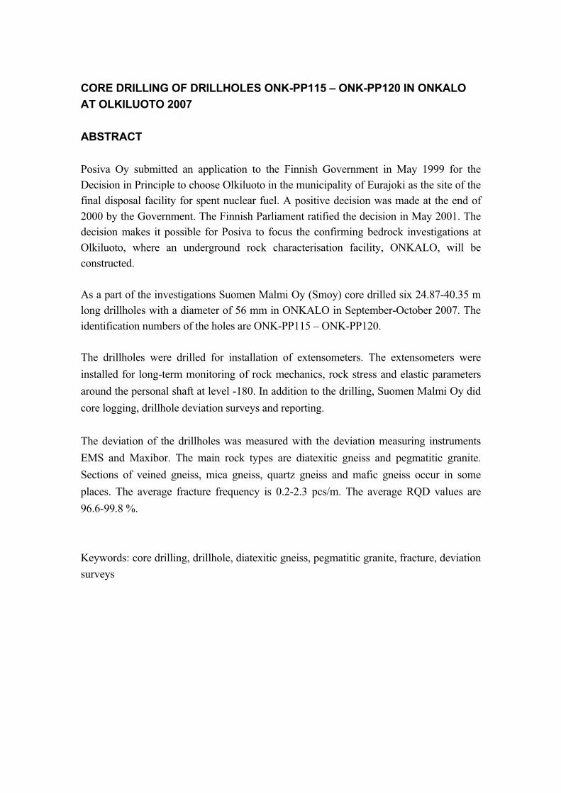
CORE DRILLING OF DRILLHOLES ONK-PP115 – ONK-PP120 IN ONKALO
AT OLKILUOTO 2007
ABSTRACT
Posiva Oy submitted an application to the Finnish Government in May 1999 for the
Decision in Principle to choose Olkiluoto in the municipality of Eurajoki as the site of the
final disposal facility for spent nuclear fuel. A positive decision was made at the end of
2000 by the Government. The Finnish Parliament ratified the decision in May 2001. The
decision makes it possible for Posiva to focus the confirming bedrock investigations at
Olkiluoto, where an underground rock characterisation facility, ONKALO, will be
constructed.
As a part of the investigations Suomen Malmi Oy (Smoy) core drilled six 24.87-40.35 m
long drillholes with a diameter of 56 mm in ONKALO in September-October 2007. The
identification numbers of the holes are ONK-PP115 – ONK-PP120.
The drillholes were drilled for installation of extensometers. The extensometers were
installed for long-term monitoring of rock mechanics, rock stress and elastic parameters
around the personal shaft at level -180. In addition to the drilling, Suomen Malmi Oy did
core logging, drillhole deviation surveys and reporting.
The deviation of the drillholes was measured with the deviation measuring instruments
EMS and Maxibor. The main rock types are diatexitic gneiss and pegmatitic granite.
Sections of veined gneiss, mica gneiss, quartz gneiss and mafic gneiss occur in some
places. The average fracture frequency is 0.2-2.3 pcs/m. The average RQD values are
96.6-99.8 %.
Keywords: core drilling, drillhole, diatexitic gneiss, pegmatitic granite, fracture, deviation
surveys
REIKIEN ONK-PP115 – ONK-PP120 KAIRAUS ONKALOSSA, EURAJOEN
OLKILUODOSSA 2007
TIIVISTELMÄ
Posiva Oy jätti valtioneuvostolle vuonna 1999 periaatepäätöshakemuksen, jolla se haki
lupaa valita Eurajoen Olkiluoto käytetyn ydinpolttoaineen loppusijoituslaitoksen
rakennuspaikaksi. Joulukuussa 2000 valtioneuvosto teki asiasta myönteisen päätöksen.
Toukokuussa 2001 eduskunta vahvisti valtioneuvoston päätöksen. Periaate-
päätöshakemuksen mukaisesti paikkatutkimukset keskitetään Olkiluotoon.
Paikkatutkimuksiin liittyen Suomen Malmi Oy (Smoy) kairasi syys-lokakuun 2007
välisenä aikana 24,87-40,35 m pituiset reiät ONK-PP115 – ONK-PP120 ONKALOssa.
Reikien halkaisija on 56 mm, taipumat mitattiin EMS ja Maxibor -laitteilla.
Kuusi reikää kairattiin ekstensometrien asentamiseksi. Niiden tarkoitus on
kalliomekaniikan, kallion jännitystilan ja muodonmuutosominaisuuksien
pitkäaikaisseuranta henkilökuilun profiilin kohdalla.
Pääkivilajit ovat diateksiittinen gneissi ja pegmatiittinen graniitti. Lisäksi tavataan paikoin
suonigneissiä, kiillegneissiä, kvartsigneissiä ja mafista gneissiä. Kallion keskimääräinen
rakoluku on 0,2-2,3 kpl/m, keskimääräinen RQD-luku on 96,6-99,8 %.
Avainsanat: kairaus, kairanreikä, diateksiittinen gneissi, pegmatiittinen graniitti, rako,
taipumamittaus
1
TABLE OF CONTENTS
ABSTRACT
TIIVISTELMÄ
1. INTRODUCTION .................................................................................................... 3 1.1 Background....................................................................................................... 3 1.2 Scope of the work ............................................................................................. 3
2. DRILLING WORK ................................................................................................... 5 2.1 Diamond core drilling ........................................................................................ 5 2.2 Location and deviation surveys ........................................................................ 5
3. GEOLOGICAL LOGGING ...................................................................................... 7 3.1 General ............................................................................................................. 7 3.2 Lithology ........................................................................................................... 7 3.3 Foliation ............................................................................................................ 9 3.4 Fracturing........................................................................................................ 10 3.5 Fracture frequency and RQD.......................................................................... 13 3.6 Weathering ..................................................................................................... 13 3.7 Core orientation .............................................................................................. 14
4. ROCK MECHANICS............................................................................................. 17
5. SUMMARY ........................................................................................................... 19
REFERENCES ............................................................................................................ 21
APPENDICES
1.1 List of core boxes............................................................................................ 23 1.2 List of lifts........................................................................................................ 25 1.3 Deviation surveys, list, Maxibor ...................................................................... 27 1.4 Deviation surveys, list, EMS ........................................................................... 33 1.5 Petrographical description .............................................................................. 39 1.6 Degree of weathering .................................................................................... 41 1.7 Foliation .......................................................................................................... 43 1.8 List of fractures ............................................................................................... 45 1.9 Fracture frequency and RQD.......................................................................... 53 1.10 Core orientation ............................................................................................ 59 1.11 Q-classification ............................................................................................. 61
PHOTOS..................................................................................................................... 67

2
1. INTRODUCTION
1.1 Background
Posiva Oy submitted an application to the Finnish Government in May 1999 for the
Decision in Principle to choose Olkiluoto in the municipality of Eurajoki as the site of the
final disposal facility for spent nuclear fuel. The Government made a positive decision at
the end of 2000. The Finnish Parliament ratified the decision in May 2001.
The policy decision makes it possible to concentrate the research activities at Olkiluoto in
Eurajoki. One part of the research is to build an underground rock characterisation facility
(called “ONKALO”). Construction of the access tunnel was started in autumn 2004.
Posiva Oy contracted (order number 9373-07) Suomen Malmi Oy (Smoy) to drill six
drillholes in ONKALO. In September-October 2007 drillholes ONK-PP115 (35.01 m),
ONK-PP116 (35.04 m), ONK-PP117 (40.35 m), ONK-PP118 (25.70 m), ONK-PP119
(24.87 m) and ONK-PP120 (25.00 m) were core drilled. The drillholes were drilled for
installation of extensometers.
The locations, azimuths and dips of the drillholes are presented in Appendices 7.3 and
7.4.
1.2 Scope of the work
The aim of the work was to drill six drillholes (Ø 56 mm, lengths between 24.87-40.35 m)
for installation of extensometers. The extensometers were installed for long-term
monitoring of rock mechanics, rock stress and elastic parameters around the personal
shaft (Figure 1). In addition to the drilling Suomen Malmi Oy did core logging, drillhole
deviation surveys and reporting. This report documents the performed work during
drilling of the drillholes. This report doesn’t include work done with extensometers.
3
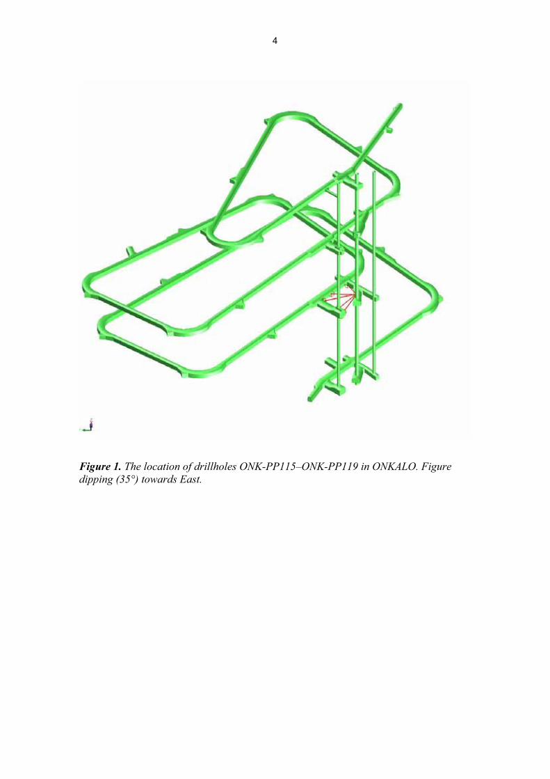
Figure 1. The location of drillholes ONK-PP115–ONK-PP119 in ONKALO. Figure
dipping (35°) towards East.
4
2. DRILLING WORK
2.1 Diamond core drilling
The diamond core drilling was done in September-October 2007. The drillholes were
started from the tunnel wall. The drillholes were core drilled with a hydraulic Diamec U6
drill rig. Drillhole diameter is 56 mm and drill core diameter is 42 mm.
Drilling crew consisted of a driller and an assistant. Geologist Tauno Rautio was the
project manager. Geological logging and compilation of the final report was done by
geologist Esa Pohjolainen.
Drill core samples were placed in wooden core boxes immediately after emptying the
core barrel. Start and end depths of the core in each core box are presented in Appendix
7.1. Wooden blocks separating the different sample runs were placed to core boxes to
show the depth of each lift. Depths of lifts are presented in Appendix 7.2.
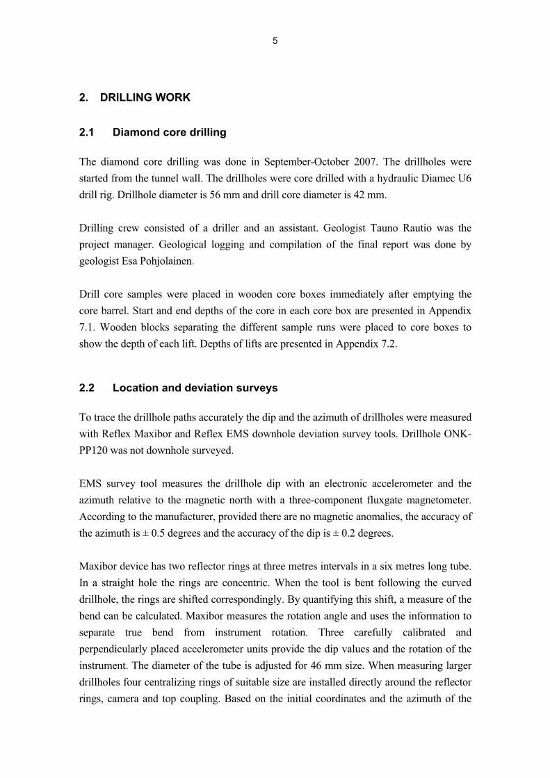
2.2 Location and deviation surveys
To trace the drillhole paths accurately the dip and the azimuth of drillholes were measured
with Reflex Maxibor and Reflex EMS downhole deviation survey tools. Drillhole ONK-
PP120 was not downhole surveyed.
EMS survey tool measures the drillhole dip with an electronic accelerometer and the
azimuth relative to the magnetic north with a three-component fluxgate magnetometer.
According to the manufacturer, provided there are no magnetic anomalies, the accuracy of
the azimuth is ± 0.5 degrees and the accuracy of the dip is ± 0.2 degrees.
Maxibor device has two reflector rings at three metres intervals in a six metres long tube.
In a straight hole the rings are concentric. When the tool is bent following the curved
drillhole, the rings are shifted correspondingly. By quantifying this shift, a measure of the
bend can be calculated. Maxibor measures the rotation angle and uses the information to
separate true bend from instrument rotation. Three carefully calibrated and
perpendicularly placed accelerometer units provide the dip values and the rotation of the
instrument. The diameter of the tube is adjusted for 46 mm size. When measuring larger
drillholes four centralizing rings of suitable size are installed directly around the reflector
rings, camera and top coupling. Based on the initial coordinates and the azimuth of the
5
hole and the deviation readings of the reflector rings a computer program calculates the
coordinates and direction of the hole at each survey station. The results are presented as a
table. According to the manufacturer typical accuracy in 800 metres deep drillhole with a
diameter of 46 mm is ± 1 m. The Maxibor survey was carried out at three metres
intervals.
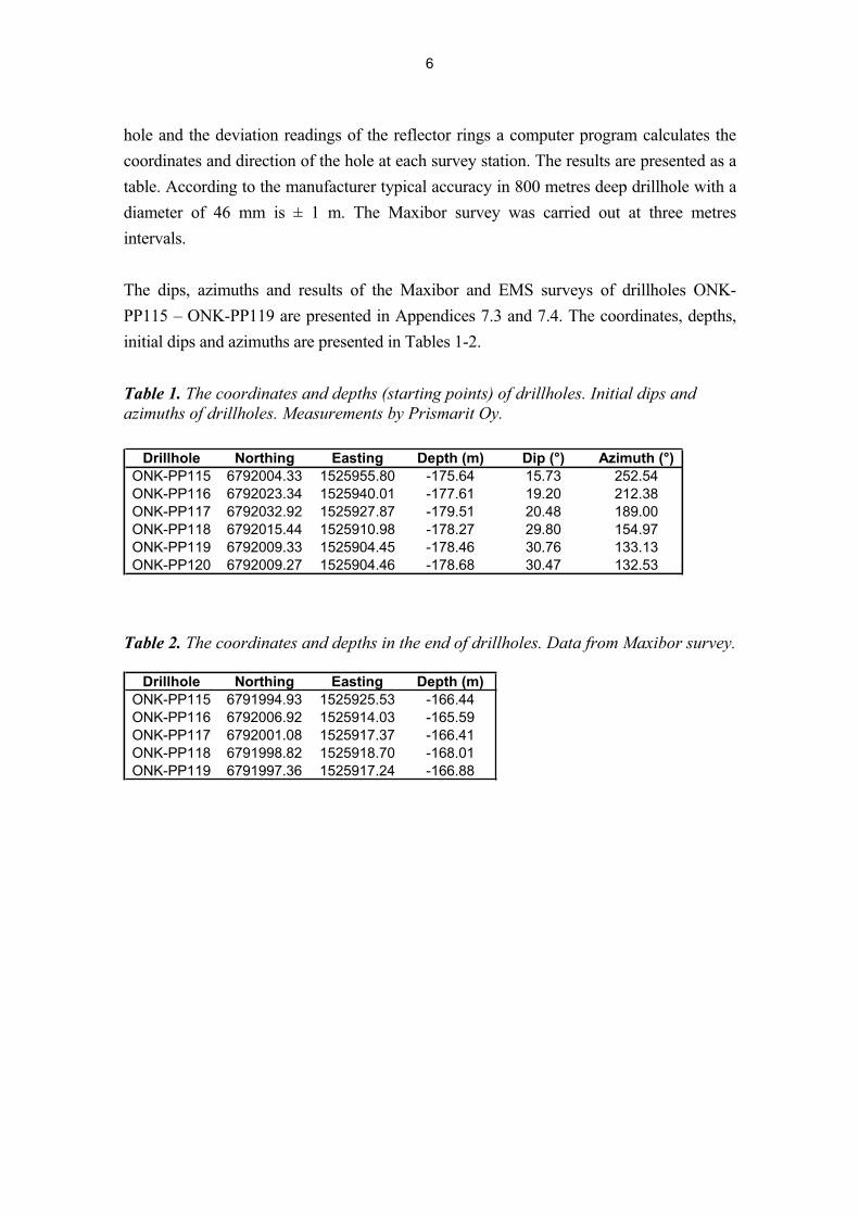
The dips, azimuths and results of the Maxibor and EMS surveys of drillholes ONK-
PP115 – ONK-PP119 are presented in Appendices 7.3 and 7.4. The coordinates, depths,
initial dips and azimuths are presented in Tables 1-2.
Table 1. The coordinates and depths (starting points) of drillholes. Initial dips and
azimuths of drillholes. Measurements by Prismarit Oy.
Drillhole Northing Easting Depth (m) Dip (°) Azimuth (°)ONK-PP115 6792004.33 1525955.80 -175.64 15.73 252.54
ONK-PP116 6792023.34 1525940.01 -177.61 19.20 212.38
ONK-PP117 6792032.92 1525927.87 -179.51 20.48 189.00
ONK-PP118 6792015.44 1525910.98 -178.27 29.80 154.97
ONK-PP119 6792009.33 1525904.45 -178.46 30.76 133.13
ONK-PP120 6792009.27 1525904.46 -178.68 30.47 132.53
Table 2. The coordinates and depths in the end of drillholes. Data from Maxibor survey.
Drillhole Northing Easting Depth (m)ONK-PP115 6791994.93 1525925.53 -166.44
ONK-PP116 6792006.92 1525914.03 -165.59
ONK-PP117 6792001.08 1525917.37 -166.41
ONK-PP118 6791998.82 1525918.70 -168.01
ONK-PP119 6791997.36 1525917.24 -166.88
6
3. GEOLOGICAL LOGGING
3.1 General
Drill core samples were placed in to about one-metre long wooden core boxes
immediately after emptying the core barrel. Drill core was handled especially carefully
during and after the drilling. Core was placed in the boxes avoiding any unnecessary
breakage.
Geologist logged the core in the Posiva’s core logging facility. The core logging followed
the normal Posiva logging procedure. Following parameters were logged: lithology,
foliation, fracture parameters, fractured zones, weathering, core loss, artificial break,
fracture frequency, RQD, rock quality and core discing. In addition, core orientation, the
lifts and the core box numbers were documented.
All core boxes were photographed (colour) both dry and wet. Core photographs (wet) are
presented at the end of this report.
List of lift depths is given as it has been marked on the spacing wooden blocks separating
different sample runs in the core boxes. If the length of the core in the sample run
indicated that sampling depth was different from the depth measured during drilling, the
true sample depth has been corrected on the spacing block. Therefore, the sample run
depth means the sample depth. The drilling depth might be deeper than the sampling
depth if the core lifter slips and part of the core is left in the drillhole and is not retrieved
until with the next lift. The measured true sample depths are marked to the core sample
with short red lines perpendicular to the core direction in one metre’s interval. The mark’s
depth metre numbers are marked to the upper dividing wall of the core box row.
3.2 Lithology
The rocks of Olkiluoto fall into four main groups: 1) gneisses, 2) migmatitic gneisses, 3)
TGG-gneisses (TGG =tonalite-granodiorite-granite) and 4) pegmatitic granites (Kärki &
Paulamäki 2006). In addition, narrow diabase dykes occur sporadically. The gneisses
include homogeneous mica-bearing quartz gneisses, banded mica gneisses and
hornblende or pyroxene-bearing mafic gneisses. The migmatitic gneisses, which typically
comprise 20–40 % leucosome, can be divided into three subgroups in terms of their
migmatite structures: veined gneisses, stromatic gneisses and diatexitic gneisses. The
7

leucosomes of the veined gneisses show vein-like, more or less elongated traces with
some features similar to augen structures. Planar leucosome layers characterize the
stromatic gneisses, while the migmatite structure of the diatexitic gneisses is asymmetric
and irregular.
The TGG gneisses are medium-grained, relatively homogeneous rocks that can show a
blastomylonitic foliation, but they can also resemble plutonic, unfoliated rocks. The
pegmatitic granites are leucocratic, very coarse-grained rocks, which may contain large
garnet, tourmaline and cordierite phenocrysts. Mica gneiss enclaves are typical of the
larger pegmatitic bodies. Gneisses, which are not at all or only weakly migmatitic, make
ca. 9 % of the bedrock. Migmatitic gneisses make up over 64 % of the volume of the
Olkiluoto bedrock, with the veined gneisses accounting for 43 %, the stromatic gneisses
for 0.4 % and the diatexitic gneisses for 21 %, based on drill core logging. Of the
remaining lithologies, TGG gneisses constitute 8 % and pegmatitic granites almost 20 %
by volume (Kärki & Paulamäki 2006).
The lithological classification used in the mapping follows the classification by Mattila
(2006). In this classification, migmatitic metamorphic gneisses are divided into veined
gneisses (VGN), stromatic gneisses (SGN) and diatexitic gneisses (DGN). The percentage
of the leucosome proportion in gneisses was reported. The non-migmatitic metamorphic
gneisses are separated into mica gneisses (MGN), mafic gneisses (MFGN), quartz
gneisses (QGN) and tonalitic-granodioritic-granitic gneisses (TGG). The metamorphic
rocks form a compositional series that can be separated by rock texture and the proportion
of neosome. Igneous rock names used in the classification are coarse-grained pegmatitic
granite (PGR), K-feldspar porphyry (KFP) and diabase (DB).
The ONK-PP115 – ONK-PP120 drill cores consist mostly of diatexitic gneiss and
pegmatitic granite. Migmatite structure of diatexitic gneiss approaches veined gneiss in
some places. Diatexitic gneiss (DGN) is mostly weakly or irregularly banded and contains
usually 50-70 % leucosome.
Pegmatitic granite (PGR) occurs both as large and uniform sections and as short sections
and veins among diatexitic gneiss.
Diatexitic gneiss contains sections of mica gneiss (MGN), quartz gneiss (QGN) and mafic
gneiss (MFGN), which were logged usually as separated rock types when sections were
wider than about one meter. The lithologies recorded from the cores are presented in
Appendix 7.5.
8
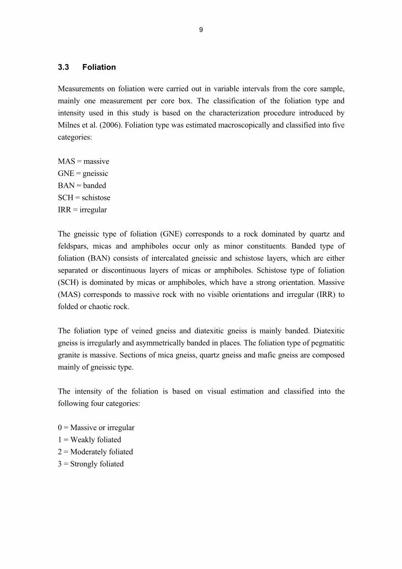
3.3 Foliation
Measurements on foliation were carried out in variable intervals from the core sample,
mainly one measurement per core box. The classification of the foliation type and
intensity used in this study is based on the characterization procedure introduced by
Milnes et al. (2006). Foliation type was estimated macroscopically and classified into five
categories:
MAS = massive
GNE = gneissic
BAN = banded
SCH = schistose
IRR = irregular
The gneissic type of foliation (GNE) corresponds to a rock dominated by quartz and
feldspars, micas and amphiboles occur only as minor constituents. Banded type of
foliation (BAN) consists of intercalated gneissic and schistose layers, which are either
separated or discontinuous layers of micas or amphiboles. Schistose type of foliation
(SCH) is dominated by micas or amphiboles, which have a strong orientation. Massive
(MAS) corresponds to massive rock with no visible orientations and irregular (IRR) to
folded or chaotic rock.
The foliation type of veined gneiss and diatexitic gneiss is mainly banded. Diatexitic
gneiss is irregularly and asymmetrically banded in places. The foliation type of pegmatitic
granite is massive. Sections of mica gneiss, quartz gneiss and mafic gneiss are composed
mainly of gneissic type.
The intensity of the foliation is based on visual estimation and classified into the
following four categories:
0 = Massive or irregular
1 = Weakly foliated
2 = Moderately foliated
3 = Strongly foliated
9
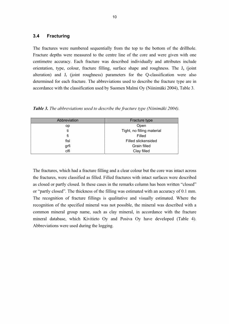
3.4 Fracturing
The fractures were numbered sequentially from the top to the bottom of the drillhole.
Fracture depths were measured to the centre line of the core and were given with one
centimetre accuracy. Each fracture was described individually and attributes include
orientation, type, colour, fracture filling, surface shape and roughness. The Ja (joint
alteration) and Jr (joint roughness) parameters for the Q-classification were also
determined for each fracture. The abbreviations used to describe the fracture type are in
accordance with the classification used by Suomen Malmi Oy (Niinimäki 2004), Table 3.
Table 3. The abbreviations used to describe the fracture type (Niinimäki 2004).
Abbreviation Fracture type
op Open
ti Tight, no filling material
fi Filled
fisl Filled slickensided
grfi Grain filled
clfi Clay filled
The fractures, which had a fracture filling and a clear colour but the core was intact across
the fractures, were classified as filled. Filled fractures with intact surfaces were described
as closed or partly closed. In these cases in the remarks column has been written “closed”
or “partly closed”. The thickness of the filling was estimated with an accuracy of 0.1 mm.
The recognition of fracture fillings is qualitative and visually estimated. Where the
recognition of the specified mineral was not possible, the mineral was described with a
common mineral group name, such as clay mineral, in accordance with the fracture
mineral database, which Kivitieto Oy and Posiva Oy have developed (Table 4).
Abbreviations were used during the logging.
10
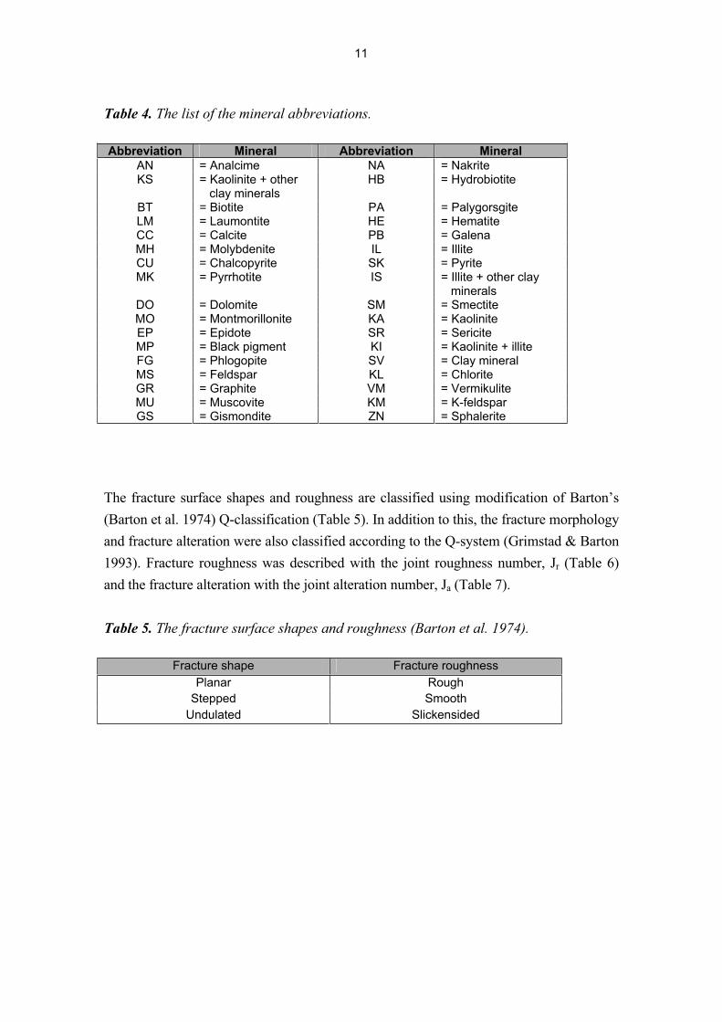
Table 4. The list of the mineral abbreviations.
Abbreviation Mineral Abbreviation MineralAN = Analcime NA = Nakrite KS = Kaolinite + other
clay minerals HB = Hydrobiotite
BT = Biotite PA = Palygorsgite LM = Laumontite HE = Hematite CC = Calcite PB = Galena MH = Molybdenite IL = Illite CU = Chalcopyrite SK = Pyrite MK = Pyrrhotite IS = Illite + other clay
minerals DO = Dolomite SM = Smectite MO = Montmorillonite KA = Kaolinite EP = Epidote SR = Sericite MP = Black pigment KI = Kaolinite + illite FG = Phlogopite SV = Clay mineral MS = Feldspar KL = Chlorite GR = Graphite VM = Vermikulite MU = Muscovite KM = K-feldspar GS = Gismondite ZN = Sphalerite
The fracture surface shapes and roughness are classified using modification of Barton’s
(Barton et al. 1974) Q-classification (Table 5). In addition to this, the fracture morphology
and fracture alteration were also classified according to the Q-system (Grimstad & Barton
1993). Fracture roughness was described with the joint roughness number, Jr (Table 6)
and the fracture alteration with the joint alteration number, Ja (Table 7).
Table 5. The fracture surface shapes and roughness (Barton et al. 1974).
Fracture shape Fracture roughness
Planar Rough
Stepped Smooth
Undulated Slickensided
11
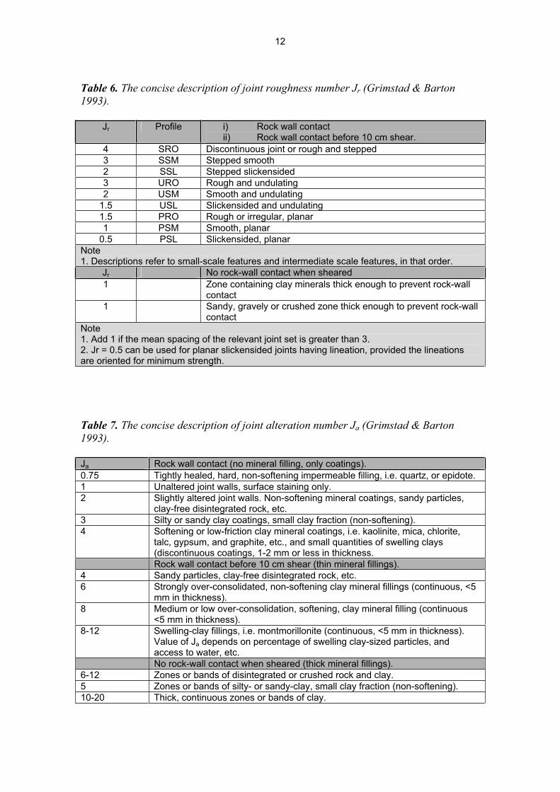
Table 6. The concise description of joint roughness number Jr (Grimstad & Barton
1993).
Jr Profile i) Rock wall contact ii) Rock wall contact before 10 cm shear.
4 SRO Discontinuous joint or rough and stepped
3 SSM Stepped smooth
2 SSL Stepped slickensided
3 URO Rough and undulating
2 USM Smooth and undulating
1.5 USL Slickensided and undulating
1.5 PRO Rough or irregular, planar
1 PSM Smooth, planar
0.5 PSL Slickensided, planar
Note1. Descriptions refer to small-scale features and intermediate scale features, in that order.
Jr No rock-wall contact when sheared
1 Zone containing clay minerals thick enough to prevent rock-wall contact
1 Sandy, gravely or crushed zone thick enough to prevent rock-wall contact
Note1. Add 1 if the mean spacing of the relevant joint set is greater than 3. 2. Jr = 0.5 can be used for planar slickensided joints having lineation, provided the lineations are oriented for minimum strength.
Table 7. The concise description of joint alteration number Ja (Grimstad & Barton
1993).
Ja Rock wall contact (no mineral filling, only coatings).
0.75 Tightly healed, hard, non-softening impermeable filling, i.e. quartz, or epidote.
1 Unaltered joint walls, surface staining only.
2 Slightly altered joint walls. Non-softening mineral coatings, sandy particles, clay-free disintegrated rock, etc.
3 Silty or sandy clay coatings, small clay fraction (non-softening).
4 Softening or low-friction clay mineral coatings, i.e. kaolinite, mica, chlorite, talc, gypsum, and graphite, etc., and small quantities of swelling clays (discontinuous coatings, 1-2 mm or less in thickness.
Rock wall contact before 10 cm shear (thin mineral fillings).
4 Sandy particles, clay-free disintegrated rock, etc.
6 Strongly over-consolidated, non-softening clay mineral fillings (continuous, <5 mm in thickness).
8 Medium or low over-consolidation, softening, clay mineral filling (continuous <5 mm in thickness).
8-12 Swelling-clay fillings, i.e. montmorillonite (continuous, <5 mm in thickness). Value of Ja depends on percentage of swelling clay-sized particles, and access to water, etc.
No rock-wall contact when sheared (thick mineral fillings).
6-12 Zones or bands of disintegrated or crushed rock and clay.
5 Zones or bands of silty- or sandy-clay, small clay fraction (non-softening).
10-20 Thick, continuous zones or bands of clay.
12
During the fracture logging the surface colour was registered. The colour is often caused
by the dominating fracture filling mineral or minerals, e.g. chlorite (green) or kaolinite
(white). Existence of minor filling minerals usually causes some variation in the colour of
the fracture surface. These shades were described e.g. as dark or greenish. Tight fractures
had typically only a slightly different shade from the host rock colour.
The main fracture fillings are calcite, kaolinite, pyrite, chlorite, chalcopyrite, muscovite
and pyrrhotite. The most common fillings are calcite, pyrite and kaolinite. Muscovite
occurs mainly on fractures, which are in pegmatitic granite. The directions of fractures
have been corrected using the data measured by Prismarit Oy.
3.5 Fracture frequency and RQD
Natural fracture frequency, all fractures frequency and RQD were logged on full metre
depth intervals. All fractures frequency is the number of core breaks within one metre
interval, including breaks and natural fractures. Drilling, core handling, core discing and
natural fractures cause breaks. Natural fracture frequency is the number of natural
fractures within one metre interval. If fracture frequency including all fractures is higher
than the natural fracture frequency the core must have been broken during drilling. If the
core was broken during handling accidentally or by purpose, it was marked to the core
box with letter F. If the natural fracture frequency is higher than fracture frequency
including all fractures the fractures must be cohesive enough to keep the core together.
RQD gives the percentage of over 10 cm long core segments, which are separated by
natural fractures, within one metre interval.
The average fracture frequencies of the cores are 0.5 pcs/m (ONK-PP115), 0.2 pcs/m
(ONK-PP116), 1.0 pcs/m (ONK-PP117), 1.1 pcs/m (ONK-PP118), 1.8 pcs/m (ONK-
PP119) and 2.3 pcs/m (ONK-PP120). The average RQD values are 99.6 % (ONK-
PP115), 99.8 % (ONK-PP116), 98.6 % (ONK-PP117), 99.0 % (ONK-PP118), 97.6 %
(ONK-PP119) and 96.6 % (ONK-PP120). Fracture frequency and RQD are presented in
Appendix 7.9.
3.6 Weathering
The weathering degree of the drill core was classified according to the method developed
by Korhonen et al. (1974) and Gardemeister et al. (1976); the abbreviations are presented
in Table 8.
13
Table 8. The abbreviations of the weathering degree.
Abbreviation Description of weathering type
Rp0 Unweathered
Rp1 Slightly weathered
Rp2 Strongly weathered
Rp3 Completely weathered
Most of the drillholes are unweathered (Rp0), having only weak and mainly local
alteration. Unweathered (Rp0) and slightly weathered (Rp1) sections contain weak
epidotization and kaolinitization in some places. The alteration of unweathered rock is
mainly related to surroundings of fractures. Slight epidotization of plagioclase and
kaolinitization on foliation planes occur in places. Pinitization of cordierite occurs
generally. Weathering degree is presented in Appendix 7.6.
3.7 Core orientation
Core orientation was carried out by using spike tool, apart from the drillhole ONK-PP120,
which was not orientated. Orientation of samples was used to determine the direction of
fractures and other linear and planar features in the core. The depth of each run where the
core has been orientated has been recorded. Also the start and end depths and the length
of the orientated part of the sample have been marked. If the mark has been rejected (not
found, poor mark), there is a comment of this in the list. The deviation of orientation
marks from the drawn orientation line was also measured as degrees.
The aim was to orientate as much core as possible in order to measure geological features.
Orientation lines were drawn on basis of several marks, if possible. The results of core
orientation are shown in Appendix 7.10.
The line drawn to the drill core sample on basis of orientation marks acted as a ground for
the direction measurements from the sample. From the orientated drill core sections core
alpha and beta angles of every fracture were measured (Figure 2). Each alpha and beta
value was recalculated to real dip and dip directions (Appendix 7.8) using the data
measured by Prismarit Oy.
14
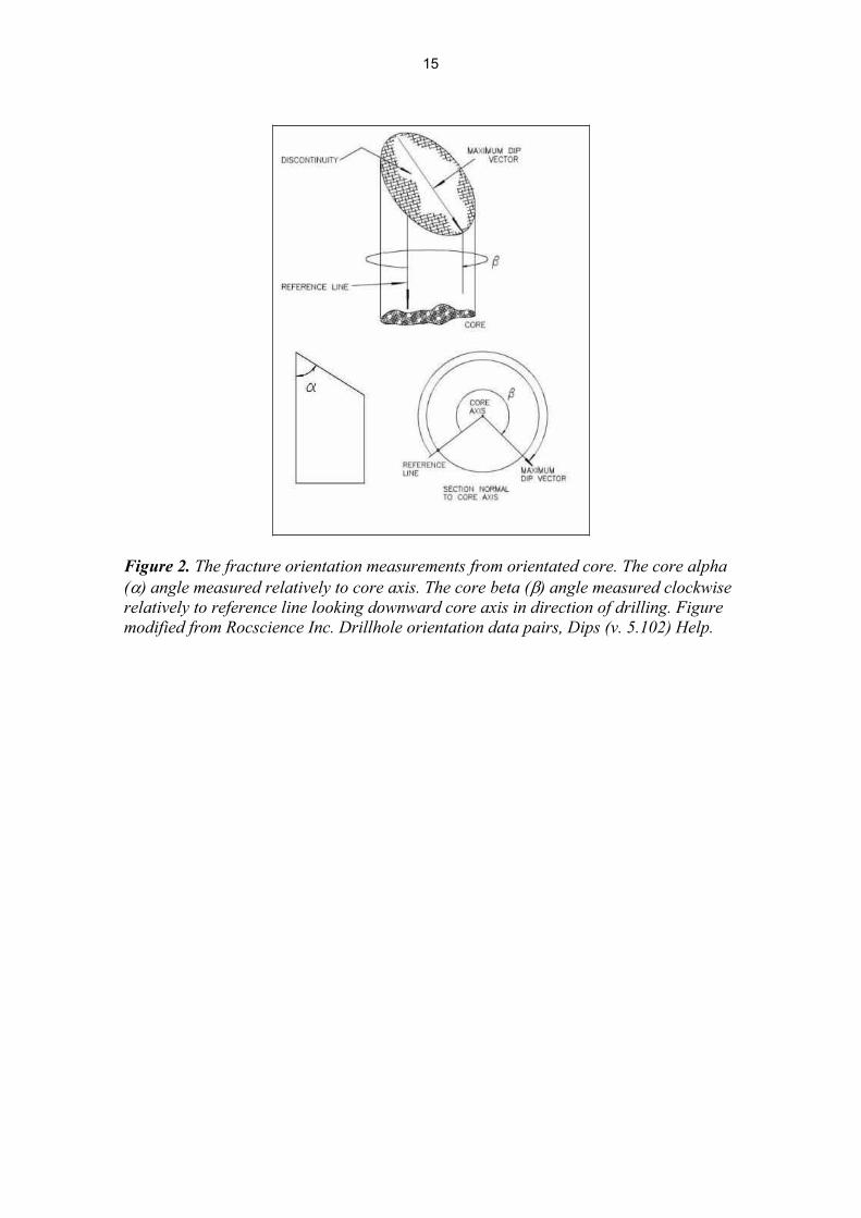
Figure 2. The fracture orientation measurements from orientated core. The core alpha
( ) angle measured relatively to core axis. The core beta ( ) angle measured clockwise
relatively to reference line looking downward core axis in direction of drilling. Figure
modified from Rocscience Inc. Drillhole orientation data pairs, Dips (v. 5.102) Help.
15

16
4. ROCK MECHANICS
The rock quality was classified using Barton’s Q-classification (Rock Tunneling Quality
Index, Barton, 1974 and Grimstad & Barton, 1993) during the core logging. The Q-
classification was used as basis for the rock mechanical logging. The core was visually
divided into sections based on the Q-value, the lengths of which can vary from less than a
metre to several meters. In each section the rock quality is as homogenous as possible.
The roughness and alteration numbers are estimated for each fracture surface, and for
each section the roughness and alteration numbers are calculated (average, median and
lower and higher quartiles) and the median value is used in the Q-quality calculations.
The roughness and alteration numbers are listed in the fracture table, Appendix 7.8. RQD
is defined as the cumulative length of core pieces longer than 10 cm in a run divided by
the total length of the core run.
Q-value is calculated by equation 1 (Barton, 1974 and Grimstad & Barton, 1993):
SRF
J
J
J
J
RQDQ w
a
r
n
** (1)
Some constant values have been used in calculations. All fractures, which are closed, are
classified in joint alteration (Ja) as number 0.75. These closed fractures are counted as
well in RQD value. If the fracture interval of the relevant joint set is over three meters, the
value of 1 is added to Jr and Jn is given the value 0.5 (Table 9). The rock sections without
any fractures, are given the value of 5 for Jr and the value of 0.75 for Ja. In calculations
joint water (Jw) and stress reduction factors (SRF) are assumed to be 1. The rock quality
of drillholes ONK-PP115–120 is mainly “extremely good” or “exceptionally good”, “very
good” in places. Results (Q) are presented in Appendix 7.11.
17
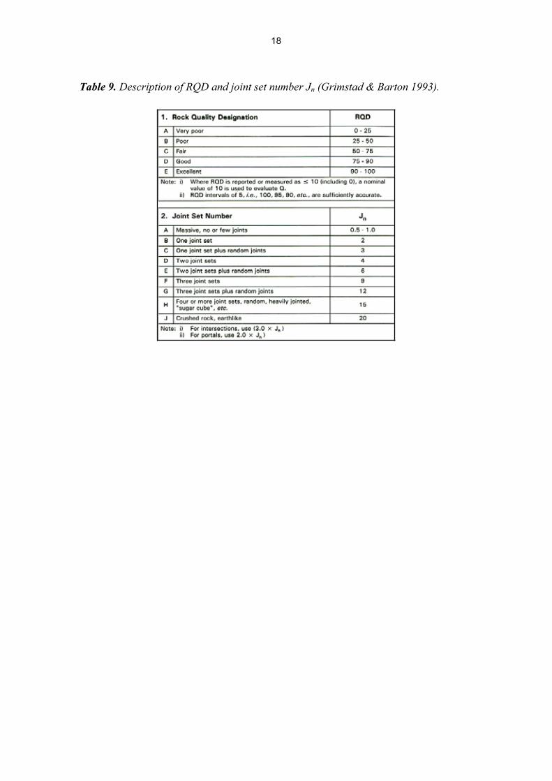
Table 9. Description of RQD and joint set number Jn (Grimstad & Barton 1993).
18
5. SUMMARY
Suomen Malmi Oy (Smoy) core drilled six 24.87-40.35 m long drillholes with a diameter
of 56 mm in ONKALO in September-October 2007. The drillholes were drilled for
installation of extensometers. The identification numbers of the drillholes are ONK-
PP115 – ONK-PP120.
The extensometers were installed for long-term monitoring of rock mechanics, rock stress
and elastic parameters around the personal shaft at level -180. In addition to the drilling
Suomen Malmi Oy did core logging, drillhole deviation surveys and reporting.
The deviation of the drillholes was measured with the deviation measuring instruments
EMS and Maxibor. The main rock types are diatexitic gneiss and pegmatitic granite.
Sections of veined gneiss, mica gneiss, quartz gneiss and mafic gneiss occur in places.
Rock samples are mostly unweathered or slightly weathered. The average fracture
frequency is 0.2-2.3 pcs/m. The average RQD values are 96.6-99.8 %.
19

20
REFERENCES
Barton, N., Lien, R. & Lunde, J. 1974. Engineering classification of rock masses for the
design of tunnel support. Rock Mechanics. December 1974. Vol. 6 No. 4. Springer
Verlag. Wien, New York. 189-236 pp.
Gardemeister, R., Johansson, S., Korhonen, P., Patrikainen, P., Tuisku, T. & Vähäsarja, P.
1976. Rakennusgeologisen kallioluokituksen soveltaminen. (The application of Finnish
engineering geological bedrock classification, in Finnish). Espoo: Technical Recearch
Centre of Finland, Geotechnical laboratory. 38 p. Research note 25.
Grimstad, E. & Barton, N. 1993. Updating of the Q-system for NMT. Proceedings of
Sprayed Concrete, 18-21 December 1993. Fagernäs. Norway
Korhonen, K-H., Gardemeister, R., Jääskeläinen, H., Niini, H. & Vähäsarja, P. 1974.
Rakennusalan kallioluokitus. (Engineering geological bedrock classification, in Finnish).
Espoo: Technical Research Centre of Finland, Geotechnical laboratory. 78 p. Research
note 12.
Kärki. A. & Paulamäki, S. 2006. Petrology of Olkiluoto. POSIVA 2006-02. Posiva Oy,
Eurajoki.
Mattila, J. 2006. A System of Nomenclature for Rocks in Olkiluoto. Eurajoki, Finland:
Posiva Oy. Posiva Working report 2006-32.
Milnes, A. G., Hudson, J., Wikström, L. & Aaltonen, I. 2006. Foliation: Geological
Background, Rock Mechanics Significance, and Preliminary Investigations at Olkiluoto.
Working Report 2006-03. Posiva Oy, Eurajoki.
Niinimäki, R. 2004. Core drilling of Pilot Hole OL-PH1 at Olkiluoto in Eurajoki 2003-
2004. Eurajoki, Finland: Posiva Oy. Posiva Working report 2004-05, 95 p.
21

22
ONK-PP115 ONK-PP118
BOX M FROM M TO BOX M FROM M TO
NUMBER m m NUMBER m m
1 0.00 5.44 1 0.00 5.38
2 5.44 10.85 2 5.38 10.75
3 10.85 16.33 3 10.75 16.35
4 16.33 21.74 4 16.35 22.01
5 21.74 27.29 5 22.01 25.70
6 27.29 32.83
7 32.83 35.01
ONK-PP116 ONK-PP119
BOX M FROM M TO BOX M FROM M TO
NUMBER m m NUMBER m m
1 0.00 5.67 1 0.00 5.42
2 5.67 11.24 2 5.42 10.71
3 11.24 16.66 3 10.71 16.18
4 16.66 22.29 4 16.18 21.59
5 22.29 27.70 5 21.59 24.87
6 27.70 33.16
7 33.16 35.04
ONK-PP117 ONK-PP120
BOX M FROM M TO BOX M FROM M TO
NUMBER m m NUMBER m m
1 0.00 5.58 1 0.00 5.02
2 5.58 10.84 2 5.02 10.54
3 10.84 16.42 3 10.54 16.19
4 16.42 21.87 4 16.19 21.56
5 21.87 27.39 5 21.56 25.00
6 27.39 32.99
7 32.99 38.33
8 38.33 40.35
23List of core boxes Appendix 1.1

24
ONK-PP115 ONK-PP118
LIFT NR LIFT DEPTH LENGTH REMARKS LIFT NR LIFT DEPTH LENGTH REMARKS
m m m m
0 0.00 Start of drilling 0 0.00 Start of drilling
1 1.84 1.84 1 1.49 1.49
2 4.83 2.99 2 4.50 3.01
3 7.84 3.01 3 7.50 3.00
4 10.85 3.01 4 10.50 3.00
5 12.09 1.24 5 13.49 2.99
6 15.10 3.01 6 16.46 2.97
7 18.09 2.99 7 19.48 3.02
8 21.10 3.01 8 22.50 3.02
9 24.10 3.00 9 25.28 2.78
10 27.10 3.00 10 25.70 0.42
11 30.63 3.53
12 33.70 3.07
13 35.01 1.31
ONK-PP116 ONK-PP119
LIFT NR LIFT DEPTH LENGTH REMARKS LIFT NR LIFT DEPTH LENGTH REMARKS
m m m m
0 0.00 Start of drilling 0 0.00 Start of drilling
1 1.15 1.15 1 1.66 1.66
2 2.17 1.02 2 4.63 2.97
3 4.73 2.56 3 5.61 0.98
4 7.70 2.97 4 7.45 1.84
5 10.68 2.98 5 10.40 2.95
6 13.70 3.02 6 13.25 2.85
7 16.66 2.96 7 16.26 3.01
8 19.58 2.92 8 19.27 3.01
9 22.58 3.00 9 20.84 1.57
10 25.60 3.02 10 22.75 1.91
11 28.61 3.01 11 24.87 2.12
12 31.64 3.03
13 34.60 2.96
14 35.04 0.44
ONK-PP117 ONK-PP120
LIFT NR LIFT DEPTH LENGTH REMARKS LIFT NR LIFT DEPTH LENGTH REMARKS
m m m m
0 0.00 Start of drilling 0 0.00 Start of drilling
1 1.55 1.55 1 1.45 1.45
2 4.08 2.53 2 3.10 1.65
3 6.50 2.42 3 4.85 1.75
4 8.97 2.47 4 5.90 1.05
5 10.48 1.51 5 7.85 1.95
6 13.50 3.02 6 10.45 2.60
7 16.49 2.99 7 12.45 2.00
8 19.50 3.01 8 13.95 1.50
9 22.50 3.00 9 17.00 3.05
10 25.50 3.00 10 20.00 3.00
11 27.90 2.40 11 22.00 2.00
12 30.90 3.00 12 25.00 3.00
13 33.89 2.99
14 36.90 3.01
15 39.68 2.78
16 40.35 0.67
25List of lifts Appendix 1.2

26
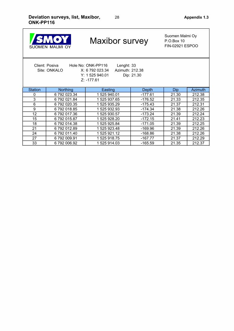
Suomen Malmi Oy
P.O.Box 10
FIN-02921 ESPOO
Client: Posiva Hole No: ONK-PP115 Lenght: 33
Site: ONKALO X: 6 792 004.33 Azimuth: 252.54
Y: 1 525 955.80 Dip: 15.90
Z: -175.64
Station Dip Azimuth
0 15.90 252.54
3 16.05 252.64
6 16.24 252.69
9 16.21 252.67
12 16.22 252.69
15 16.23 252.70
18 16.22 252.73
21 16.24 252.79
24 16.26 252.86
27 16.25 252.93
33 16.26 253.01
-168.96
-168.12
-166.44
-172.31
-171.47
-170.64
-169.80
-175.64
-174.82
-173.99
-173.15
1 525 939.30
1 525 936.55
1 525 955.80
1 525 953.05
1 525 950.30
1 525 947.55
1 525 933.79
1 525 931.04
1 525 925.53
Easting
6 791 998.32
6 791 997.47
6 791 996.62
6 791 994.93
6 792 001.75
6 792 000.89
Maxibor survey
6 792 000.03
6 791 999.18
Northing
6 792 004.33
6 792 003.46
6 792 002.60
Depth
1 525 944.80
1 525 942.05
27Deviation surveys, list, Maxibor,ONK-PP115
Appendix 1.3
Suomen Malmi Oy
P.O.Box 10
FIN-02921 ESPOO
Client: Posiva Hole No: ONK-PP116 Lenght: 33
Site: ONKALO X: 6 792 023.34 Azimuth: 212.38
Y: 1 525 940.01 Dip: 21.30
Z: -177.61
Station Dip Azimuth
0 21.30 212.38
3 21.33 212.35
6 21.37 212.31
9 21.38 212.26
12 21.39 212.24
15 21.41 212.23
18 21.39 212.25
21 21.39 212.26
24 21.38 212.26
27 21.37 212.29
33 21.35 212.37
-168.86
-167.77
-165.59
-173.24
-172.15
-171.05
-169.96
-177.61
-176.52
-175.43
-174.34
1 525 925.84
1 525 923.48
1 525 940.01
1 525 937.65
1 525 935.29
1 525 932.93
1 525 921.12
1 525 918.75
1 525 914.03
Easting
6 792 012.89
6 792 011.40
6 792 009.91
6 792 006.92
6 792 018.85
6 792 017.36
Maxibor survey
6 792 015.87
6 792 014.38
Northing
6 792 023.34
6 792 021.84
6 792 020.35
Depth
1 525 930.57
1 525 928.20
28Deviation surveys, list, Maxibor,ONK-PP116
Appendix 1.3
Suomen Malmi Oy
P.O.Box 10
FIN-02921 ESPOO
Client: Posiva Hole No: ONK-PP117 Lenght: 36
Site: ONKALO X: 6 792 032.92 Azimuth: 189.19
Y: 1 525 927.87 Dip: 21.30
Z: -179.51
Station Dip Azimuth
0 21.30 189.19
3 21.32 189.15
6 21.34 189.17
9 21.35 189.18
12 21.31 189.19
15 21.27 189.22
18 21.25 189.23
21 21.29 189.24
24 21.35 189.26
27 21.39 189.32
30 21.45 189.40
36 21.52 189.53
-170.79
-169.70
-168.60
-166.41
-175.15
-174.05
-172.97
-171.88
-179.51
-178.42
-177.33
-176.24
1 525 922.64
1 525 921.76
1 525 927.87
1 525 927.00
1 525 926.13
1 525 925.26
1 525 920.89
1 525 920.01
1 525 919.14
1 525 917.376 792 001.08
Easting
6 792 014.33
6 792 011.68
6 792 009.02
6 792 006.37
6 792 024.95
6 792 022.30
Maxibor survey
6 792 019.64
6 792 016.99
Northing
6 792 032.92
6 792 030.26
6 792 027.61
Depth
1 525 924.38
1 525 923.51
29Deviation surveys, list, Maxibor,ONK-PP117
Appendix 1.3

Suomen Malmi Oy
P.O.Box 10
FIN-02921 ESPOO
Client: Posiva Hole No: ONK-PP118 Lenght: 21
Site: ONKALO X: 6 792 015.44 Azimuth: 154.97
Y: 1 525 910.98 Dip: 28.80
Z: -178.27
Station Dip Azimuth
0 28.80 154.97
3 28.96 155.01
6 29.09 155.08
9 29.23 155.14
12 29.39 155.16
15 29.54 155.16
21 29.75 155.14
-172.45
-170.98
-168.01
-178.27
-176.82
-175.37
-173.91
1 525 918.70
1 525 910.98
1 525 912.09
1 525 913.20
1 525 914.31
Easting
6 792 008.30
6 792 005.93
Maxibor survey
6 792 003.55
6 791 998.82
Northing
6 792 015.44
6 792 013.06
6 792 010.68
Depth
1 525 915.41
1 525 916.50
30Deviation surveys, list, Maxibor,ONK-PP118
Appendix 1.3
Suomen Malmi Oy
P.O.Box 10
FIN-02921 ESPOO
Client: Posiva Hole No: ONK-PP119 Lenght: 21
Site: ONKALO X: 6 792 009.33 Azimuth: 133.13
Y: 1 525 904.45 Dip: 33.50
Z: -178.46
Station Dip Azimuth
0 33.50 133.13
3 33.50 133.12
6 33.48 133.11
9 33.45 133.10
12 33.43 133.06
15 33.43 133.04
21 33.47 133.06
-171.84
-170.19
-166.88
-178.46
-176.80
-175.15
-173.49
1 525 917.24
1 525 904.45
1 525 906.28
1 525 908.10
1 525 909.93
Easting
6 792 004.20
6 792 002.49
Maxibor survey
6 792 000.78
6 791 997.36
Northing
6 792 009.33
6 792 007.62
6 792 005.91
Depth
1 525 911.76
1 525 913.59
31Deviation surveys, list, Maxibor,ONK-PP119
Appendix 1.3

32
Suomen Malmi Oy
P.O.Box 10
FIN-02921 ESPOO
Client: Posiva Hole No: ONK-PP115 Lenght: 33
Site: ONKALO X: 6 792 004.33 Azimuth: 251.29
Y: 1 525 955.80 Dip: 15.76
Z: -175.64
Station Dip Azimuth
0 15.76 251.29
3 15.81 252.21
6 16.12 252.89
9 16.26 251.53
12 16.07 250.76
15 16.12 250.56
18 16.36 253.58
21 16.39 250.96
24 16.39 251.81
27 16.48 251.86
30 16.45 252.36
33 16.45 252.39
EMS-survey
6 791 999.83
6 791 998.94
Northing
6 792 004.33
6 792 003.46
6 792 002.59
Depth
1 525 944.83
1 525 942.11
6 791 994.49
Easting
6 791 998.06
6 791 997.14
6 791 996.25
6 791 995.36
6 792 001.71
6 792 000.78
1 525 933.90
1 525 931.17
1 525 928.43
1 525 925.69
1 525 939.37
1 525 936.63
1 525 955.80
1 525 953.05
1 525 950.30
1 525 947.56
-175.64
-174.82
-174.00
-173.16
-172.33
-171.49
-170.66
-169.81
-168.96
-168.11
-167.26
-166.41
33Deviation surveys, list, EMS,ONK-PP115
Appendix 1.4

Suomen Malmi Oy
P.O.Box 10
FIN-02921 ESPOO
Client: Posiva Hole No: ONK-PP116 Lenght: 33
Site: ONKALO X: 6 792 023.34 Azimuth: 186.98
Y: 1 525 940.01 Dip: 19.44
Z: -177.61
Station Dip Azimuth
0 19.44 186.98
3 19.45 203.05
6 19.61 206.01
9 19.62 208.69
12 19.57 209.69
15 19.51 209.61
18 19.59 209.90
21 19.57 210.02
24 19.67 209.84
27 19.66 209.80
30 19.53 209.69
33 19.57 209.89
-169.58
-168.57
-167.56
-166.56
-173.60
-172.60
-171.59
-170.59
-177.61
-176.62
-175.61
-174.61
1 525 930.92
1 525 929.41
1 525 940.01
1 525 938.49
1 525 936.98
1 525 935.47
1 525 927.90
1 525 926.39
1 525 924.87
1 525 923.366 791 997.08
Easting
6 792 006.63
6 792 004.24
6 792 001.86
6 791 999.47
6 792 016.18
6 792 013.79
EMS-survey
6 792 011.40
6 792 009.02
Northing
6 792 023.34
6 792 020.95
6 792 018.57
Depth
1 525 933.95
1 525 932.44
34Deviation surveys, list, EMS,ONK-PP116
Appendix 1.4
Suomen Malmi Oy
P.O.Box 10
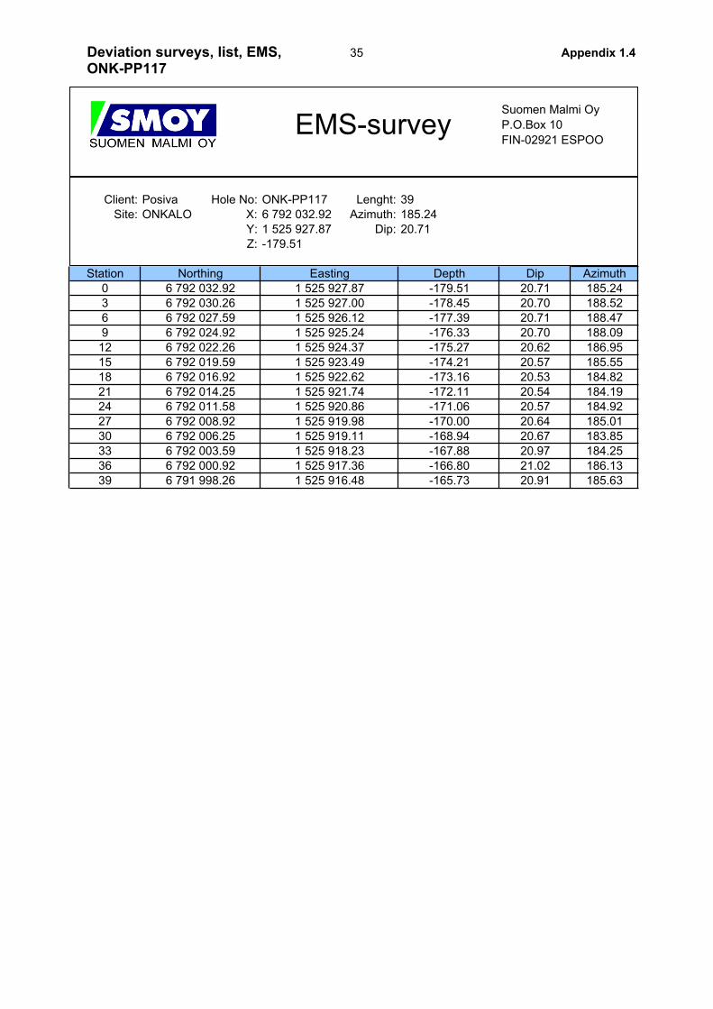
FIN-02921 ESPOO
Client: Posiva Hole No: ONK-PP117 Lenght: 39
Site: ONKALO X: 6 792 032.92 Azimuth: 185.24
Y: 1 525 927.87 Dip: 20.71
Z: -179.51
Station Dip Azimuth
0 20.71 185.24
3 20.70 188.52
6 20.71 188.47
9 20.70 188.09
12 20.62 186.95
15 20.57 185.55
18 20.53 184.82
21 20.54 184.19
24 20.57 184.92
27 20.64 185.01
30 20.67 183.85
33 20.97 184.25
36 21.02 186.13
39 20.91 185.63
EMS-survey
6 792 019.59
6 792 016.92
Northing
6 792 032.92
6 792 030.26
6 792 027.59
Depth
1 525 924.37
1 525 923.49
6 792 000.92
6 792 003.59
6 791 998.26
Easting
6 792 014.25
6 792 011.58
6 792 008.92
6 792 006.25
6 792 024.92
6 792 022.26
1 525 920.86
1 525 919.98
1 525 919.11
1 525 918.23
1 525 917.36
1 525 916.48
1 525 922.62
1 525 921.74
1 525 927.87
1 525 927.00
1 525 926.12
1 525 925.24
-179.51
-178.45
-177.39
-176.33
-175.27
-174.21
-173.16
-172.11
-171.06
-170.00
-168.94
-167.88
-166.80
-165.73
35Deviation surveys, list, EMS,ONK-PP117
Appendix 1.4
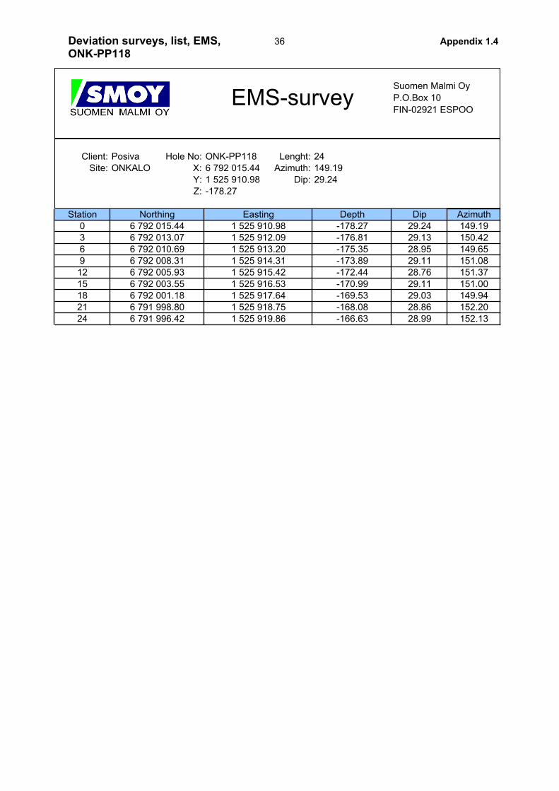
Suomen Malmi Oy
P.O.Box 10
FIN-02921 ESPOO
Client: Posiva Hole No: ONK-PP118 Lenght: 24
Site: ONKALO X: 6 792 015.44 Azimuth: 149.19
Y: 1 525 910.98 Dip: 29.24
Z: -178.27
Station Dip Azimuth
0 29.24 149.19
3 29.13 150.42
6 28.95 149.65
9 29.11 151.08
12 28.76 151.37
15 29.11 151.00
18 29.03 149.94
21 28.86 152.20
24 28.99 152.13
EMS-survey
6 792 003.55
6 792 001.18
Northing
6 792 015.44
6 792 013.07
6 792 010.69
Depth
1 525 915.42
1 525 916.53
Easting
6 791 998.80
6 791 996.42
6 792 008.31
6 792 005.93
1 525 919.86
1 525 917.64
1 525 918.75
1 525 910.98
1 525 912.09
1 525 913.20
1 525 914.31
-178.27
-176.81
-175.35
-173.89
-172.44
-170.99
-169.53
-168.08
-166.63
36Deviation surveys, list, EMS,ONK-PP118
Appendix 1.4

Suomen Malmi Oy
P.O.Box 10
FIN-02921 ESPOO
Client: Posiva Hole No: ONK-PP119 Lenght: 21
Site: ONKALO X: 6 792 009.33 Azimuth: 129.40
Y: 1 525 904.45 Dip: 30.33
Z: -178.46
Station Dip Azimuth
0 30.33 129.40
3 30.42 129.21
6 30.34 129.92
9 30.03 130.16
12 30.32 128.70
15 30.41 128.87
18 30.23 130.42
21 30.09 129.66
-172.40
-170.89
-169.37
-167.87
-178.46
-176.94
-175.42
-173.91
1 525 915.79
1 525 917.68
1 525 904.45
1 525 906.33
1 525 908.22
1 525 910.12
Easting
6 791 996.93
6 792 004.02
6 792 002.25
EMS-survey
6 792 000.48
6 791 998.71
Northing
6 792 009.33
6 792 007.56
6 792 005.79
Depth
1 525 912.01
1 525 913.90
37Deviation surveys, list, EMS,ONK-PP119
Appendix 1.4

38
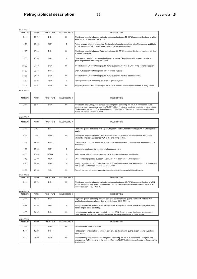
ONK-PP115
M FROM M TO ROCK TYPE LEUCOSOME % DESCRIPTION
0.00 10.70 DGN 60 Weakly and irregularly banded diatexitic gneiss containing ca. 50-80 % leucosome. Sections of MGN
and PGR occur between 5.00-10.00 m.
10.70 12.15 MGN 5 Rather strongly foliated mica gneiss. Section of mafic gneiss containing lots of hornblende and biotite
occurs between 11.00-11.50 m. MGN contains garnet porphyroblasts.
12.15 19.00 DGN 55 Weakly and irregularly banded DGN containing ca. 50-75 % leucosome. Biotite-rich parts contain lots
of fibrous sillimanite.
19.00 20.50 QGN 10 QGN section containing coarse-grained quartz in places. Skarn lenses with orange grossular and
green diopside occur all along the section.
20.50 27.50 DGN 60 Weakly banded DGN containing ca. 50-70 % leucosome. Section of QGN in the end of the section.
27.50 28.55 PGR Short PGR section containing quite a lot of apatite crystals.
28.55 31.50 DGN 60 Weakly banded DGN containing ca. 50-70 % leucosome. Quite a lot of muscovite.
31.50 33.05 QGN 0 Homogeneous QGN containing lots of small garnet crystals.
33.05 35.01 DGN 60 Irregularly banded DGN containing ca. 50-70 % leucosome. Green apatite crystals in many places.
ONK-PP116
M FROM M TO ROCK TYPE LEUCOSOME % DESCRIPTION
0.00 35.04 DGN 50 Weakly and locally irregularly banded diatexitic gneiss containing ca. 40-70 % leucosome. PGR
sections in many places, e.g. between 10.30-11.80 m. Fresh and unaltered cordierite in many places.
DGN contains quite a lot of pyrrhotite between 17.00-20.00 m. The rock approaches VGN in some
places. Also short sections of MGN.
ONK-PP117
M FROM M TO ROCK TYPE LEUCOSOME % DESCRIPTION
0.00 2.10 PGR Pegmatitic granite containing K-feldspar with graphic texture, formed by intergrowth of K-feldspar and
quartz.
2.10 5.95 DGN 50 Weakly and irregularly banded DGN. Mesosome-rich parts contain lots of cordierite, also fibrous
sillimanite. The rock approaches VGN in the end of the section.
5.95 14.00 PGR PGR contains lots of muscovite, especially in the end of the section. Pinitized cordierite grains occur
as clusters.
14.00 16.85 MGN 5 Mica gneiss section containing sparsely leucosome veins.
16.85 18.45 MFGN 5 Mafic gneiss, which is mainly composed of biotite, plagioclase and hornblende.
18.45 20.90 MGN 5 MGN containing sparsely leucosome veins. The rock approaches VGN in places.
20.90 39.00 DGN 70 Mostly irregularly banded DGN containing ca. 50-80 % leucosome. Cordierite grains occur as clusters
with quartz. QGN section between 22.28-22.77 m.
39.00 40.35 VGN 35 Strongly banded veined gneiss containing quite a lot of fibrous and whitish sillimanite.
ONK-PP118
M FROM M TO ROCK TYPE LEUCOSOME % DESCRIPTION
0.00 25.70 DGN 55 Weakly and irregularly banded diatexitic gneiss containing ca. 40-75 % leucosome. Section of VGN
occurs between 3.00-4.00 m. DGN contains lots of fibrous sillimanite between 6.00-10.00 m. PGR
section between 18.30-19.00 m.
ONK-PP119
M FROM M TO ROCK TYPE LEUCOSOME % DESCRIPTION
0.00 16.12 PGR Pegmatitic granite containing pinitized cordierite as clusters with quartz. Perthitic K-feldspar with
graphic texture in many places. Quartz vein between 11.73-11.91 m.
16.12 16.56 MGN 5 Strongly foliated and sheared MGN section, which is very rich in biotite. Biotite- and plagioclase-rich
narrow stripes occur alternately.
16.56 24.87 DGN 55 Heterogeneous and weakly or irregularly banded DGN. Some parts are dominated by mesosome,
some parts by leucosome. Leucosomes contain lots of apatite crystals in some places.
ONK-PP120
M FROM M TO ROCK TYPE LEUCOSOME % DESCRIPTION
0.00 1.00 DGN 60 Weakly banded diatexitic gneiss.
1.00 16.20 PGR PGR section containing lots of pinitized cordierite as clusters with quartz. Green apatite crystals in
some places.
16.20 25.00 DGN 50 Weakly or irregularly banded diatexitic gneiss containing ca. 30-70 % leucosome. DGN gradually
changes into VGN in the end of the section. Between 16.20-16.50 m weakly sheared section, which is
rich in biotite.
39Petrographical description Appendix 1.5

40
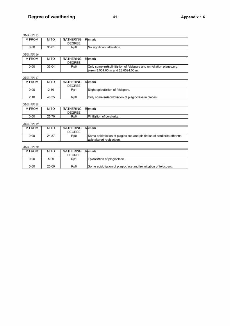
ONK-PP115
M FROM M TO WEATHERING Remarks
DEGREE
0.00 35.01 Rp0 No significant alteration.
ONK-PP116
M FROM M TO WEATHERING Remarks
DEGREE
0.00 35.04 Rp0 Only some weak kaolinitization of feldspars and on foliation planes, e.g.
between 3.00-4.00 m and 23.00-24.00 m.
ONK-PP117
M FROM M TO WEATHERING Remarks
DEGREE
0.00 2.10 Rp1 Slight epidotization of feldspars.
2.10 40.35 Rp0 Only some weak epidotization of plagioclase in places.
ONK-PP118
M FROM M TO WEATHERING Remarks
DEGREE
0.00 25.70 Rp0 Pinitization of cordierite.
ONK-PP119
M FROM M TO WEATHERING Remarks
DEGREE
0.00 24.87 Rp0 Some epidotization of plagioclase and pinitization of cordierite, otherwise
weakly altered rock section.
ONK-PP120
M FROM M TO WEATHERING Remarks
DEGREE
0.00 5.00 Rp1 Epidotization of plagioclase.
5.00 25.00 Rp0 Some epidotization of plagioclase and kaolinitization of feldspars.
41Degree of weathering Appendix 1.6

42
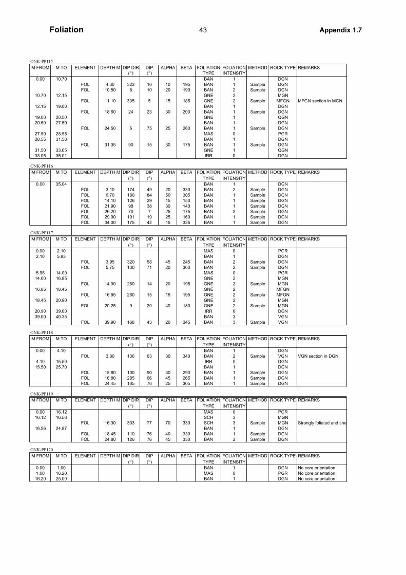
ONK-PP115
M FROM M TO ELEMENT DEPTH M DIP DIR DIP ALPHA BETA FOLIATION FOLIATION METHOD ROCK TYPE REMARKS
(°) (°) TYPE INTENSITY
0.00 10.70 BAN 1 DGN
FOL 4.30 323 16 10 195 BAN 1 Sample DGN
FOL 10.50 8 10 20 190 BAN 2 Sample DGN
10.70 12.15 GNE 2 MGN
FOL 11.10 335 5 15 185 GNE 2 Sample MFGN MFGN section in MGN
12.15 19.00 BAN 1 DGN
FOL 18.60 24 23 30 200 BAN 1 Sample DGN
19.00 20.50 GNE 1 QGN
20.50 27.50 BAN 1 DGN
FOL 24.50 5 75 25 260 BAN 1 Sample DGN
27.50 28.55 MAS 0 PGR
28.55 31.50 BAN 1 DGN
FOL 31.35 90 15 30 175 BAN 1 Sample DGN
31.50 33.05 GNE 1 QGN
33.05 35.01 IRR 0 DGN
ONK-PP116
M FROM M TO ELEMENT DEPTH M DIP DIR DIP ALPHA BETA FOLIATION FOLIATION METHOD ROCK TYPE REMARKS
(°) (°) TYPE INTENSITY
0.00 35.04 BAN 1 DGN
FOL 3.10 174 49 20 330 BAN 2 Sample DGN
FOL 6.70 180 84 50 305 BAN 1 Sample DGN
FOL 14.10 126 29 15 150 BAN 1 Sample DGN
FOL 21.90 98 38 30 140 BAN 1 Sample DGN
FOL 26.20 70 7 25 175 BAN 2 Sample DGN
FOL 29.90 101 19 25 160 BAN 1 Sample DGN
FOL 34.00 175 42 15 335 BAN 1 Sample DGN
ONK-PP117
M FROM M TO ELEMENT DEPTH M DIP DIR DIP ALPHA BETA FOLIATION FOLIATION METHOD ROCK TYPE REMARKS
(°) (°) TYPE INTENSITY
0.00 2.10 MAS 0 PGR
2.10 5.95 BAN 1 DGN
FOL 3.95 320 58 45 245 BAN 2 Sample DGN
FOL 5.75 130 71 20 300 BAN 2 Sample DGN
5.95 14.00 MAS 0 PGR
14.00 16.85 GNE 2 MGN
FOL 14.90 280 14 20 195 GNE 2 Sample MGN
16.85 18.45 GNE 2 MFGN
FOL 16.95 260 15 15 195 GNE 2 Sample MFGN
18.45 20.90 GNE 2 MGN
FOL 20.25 9 20 40 180 GNE 2 Sample MGN
20.90 39.00 IRR 0 DGN
39.00 40.35 BAN 3 VGN
FOL 39.90 168 43 20 345 BAN 3 Sample VGN
ONK-PP118
M FROM M TO ELEMENT DEPTH M DIP DIR DIP ALPHA BETA FOLIATION FOLIATION METHOD ROCK TYPE REMARKS
(°) (°) TYPE INTENSITY
0.00 4.10 BAN 1 DGN
FOL 3.80 136 63 30 340 BAN 2 Sample VGN VGN section in DGN
4.10 15.50 IRR 0 DGN
15.50 25.70 BAN 1 DGN
FOL 15.80 100 90 30 290 BAN 1 Sample DGN
FOL 16.80 285 66 45 265 BAN 1 Sample DGN
FOL 24.45 105 76 25 305 BAN 1 Sample DGN
ONK-PP119
M FROM M TO ELEMENT DEPTH M DIP DIR DIP ALPHA BETA FOLIATION FOLIATION METHOD ROCK TYPE REMARKS
(°) (°) TYPE INTENSITY
0.00 16.12 MAS 0 PGR
16.12 16.56 SCH 3 MGN
FOL 16.30 303 77 70 330 SCH 3 Sample MGN Strongly foliated and she
16.56 24.87 BAN 1 DGN
FOL 18.45 110 76 40 330 BAN 1 Sample DGN
FOL 24.80 126 76 45 350 BAN 2 Sample DGN
ONK-PP120
M FROM M TO ELEMENT DEPTH M DIP DIR DIP ALPHA BETA FOLIATION FOLIATION METHOD ROCK TYPE REMARKS
(°) (°) TYPE INTENSITY
0.00 1.00 BAN 1 DGN No core orientation
1.00 16.20 MAS 0 PGR No core orientation
16.20 25.00 BAN 1 DGN No core orientation
43Foliation Appendix 1.7

44
FR
AC
TU
RE
DE
PT
HC
OR
E A
LP
HA
CO
RE
BE
TA
CO
RE
DIR
CO
RE
DIP
CO
LO
UR
OF
FR
AC
TU
RE
TH
ICK
NE
SS
OF
T
YP
EF
RA
CT
UR
EF
RA
CT
UR
E
Jr
Ja
RE
MA
RK
S
NU
MB
ER
m(°
)(°
)(°
)(°
)F
RA
CT
UR
E S
UR
FA
CE
FIL
LIN
GF
ILL
ING
(m
m)
SH
AP
ER
OU
GH
NE
SS
31
10
.03
75
11
08
87
0ti
un
du
late
dro
ug
h3
0.7
5clo
se
d
22
.51
30
11
01
36
65
tiu
nd
ula
ted
rou
gh
31
33
.59
10
16
51
82
16
wh
ite
KA
0.1
fiu
nd
ula
ted
rou
gh
31
pa
rtly
clo
se
d
45
.11
15
36
02
53
31
ligh
t g
rey
CC
, K
A0
.3fi
un
du
late
dro
ug
h3
2
55
.95
60
13
59
85
5ti
un
du
late
dro
ug
h3
1
68
.16
15
36
02
53
31
ligh
t b
row
nS
K,
CC
0.4
fiu
nd
ula
ted
rou
gh
32
ca
lcite
cry
sta
ls
79
.20
15
36
02
53
31
wh
ite
KA
0.1
fiu
nd
ula
ted
rou
gh
31
pa
rtly
clo
se
d
89
.26
10
36
02
53
26
wh
ite
KA
0.1
fiu
nd
ula
ted
rou
gh
31
91
1.4
71
51
75
17
05
ligh
t g
rey
CC
, K
L,
SK
0.5
fip
lan
ar
sm
oo
th1
4
10
11
.64
30
20
27
55
0lig
ht
gre
yC
C0
.2fi
un
du
late
dro
ug
h3
1p
art
ly c
lose
d
11
12
.09
15
16
51
63
14
ligh
t g
rey
CC
, K
L0
.4fi
pla
na
rsm
oo
th1
4
12
13
.74
45
65
29
38
4lig
ht
gre
yC
C0
.1fi
un
du
late
dro
ug
h3
1
13
19
.87
65
28
54
88
2ti
un
du
late
dro
ug
h3
1p
art
ly c
lose
d
14
20
.54
25
21
54
34
tiu
nd
ula
ted
rou
gh
30
.75
clo
se
d
15
32
.29
50
40
27
87
5ti
un
du
late
dro
ug
h3
1
16
32
.54
70
29
05
48
2ti
pla
na
rro
ug
h1
.51
17
32
.75
65
27
54
77
8lig
ht
gre
yC
C0
.1fi
un
du
late
dro
ug
h3
1
18
32
.83
60
10
25
87
6ti
un
du
late
dro
ug
h3
1
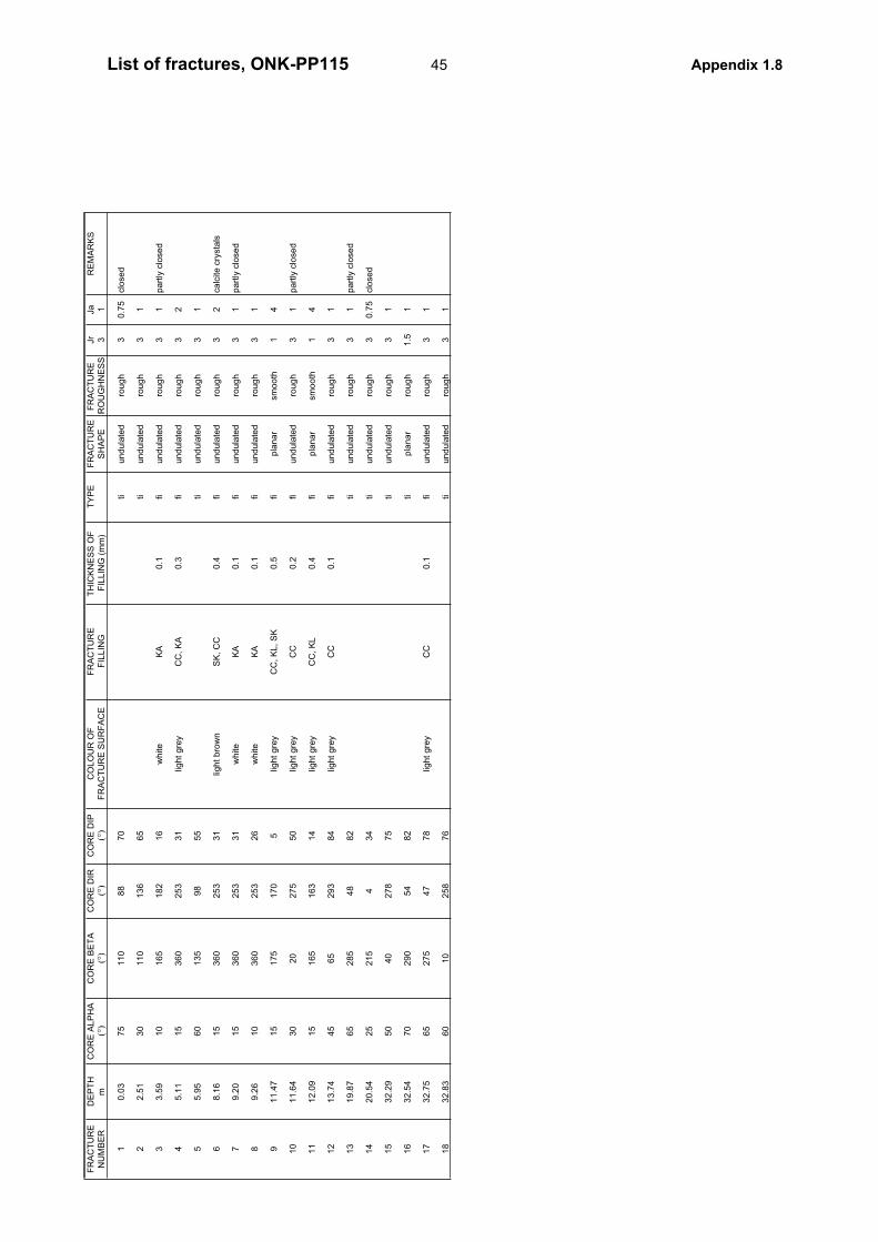
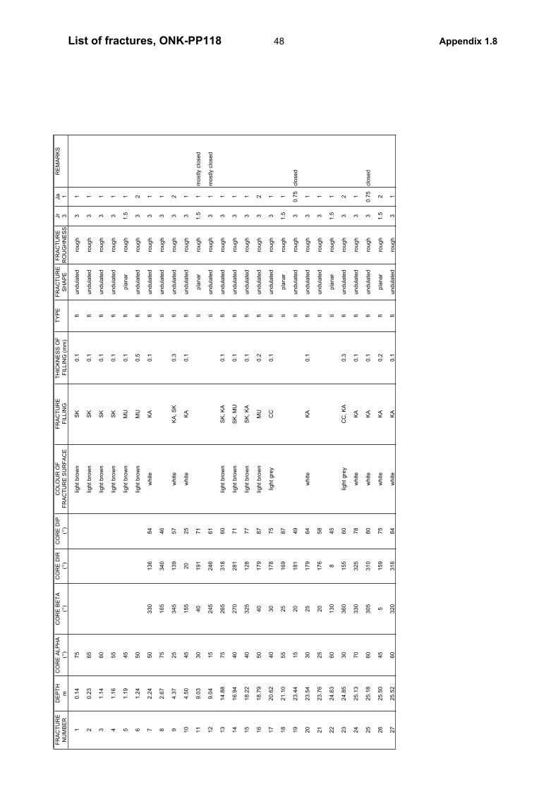
45List of fractures, ONK-PP115 Appendix 1.8
FR
AC
TU
RE
DE
PT
HC
OR
E A
LP
HA
CO
RE
BE
TA
CO
RE
DIR
CO
RE
DIP
CO
LO
UR
OF
FR
AC
TU
RE
TH
ICK
NE
SS
OF
T
YP
EF
RA
CT
UR
EF
RA
CT
UR
E
Jr
Ja
RE
MA
RK
S
NU
MB
ER
m(°
)(°
)(°
)(°
)F
RA
CT
UR
E S
UR
FA
CE
FIL
LIN
GF
ILL
ING
(m
m)
SH
AP
ER
OU
GH
NE
SS
31
13
.89
30
35
02
01
50
ligh
t g
rey
CC
, K
A0
.1fi
un
du
late
dro
ug
h3
1
22
2.2
94
53
30
19
07
0ti
un
du
late
dro
ug
h3
1
32
6.6
52
53
30
17
85
3w
hite
KA
0.2
fiu
nd
ula
ted
rou
gh
32
42
6.7
12
53
30
17
85
3w
hite
KA
0.1
fiu
nd
ula
ted
rou
gh
30
.75
clo
se
d
52
7.2
63
03
60
21
24
9w
hite
KA
0.1
fiu
nd
ula
ted
rou
gh
31
63
1.5
31
53
40
18
13
9w
hite
KA
0.1
fiu
nd
ula
ted
rou
gh
30
.75
clo
se
d
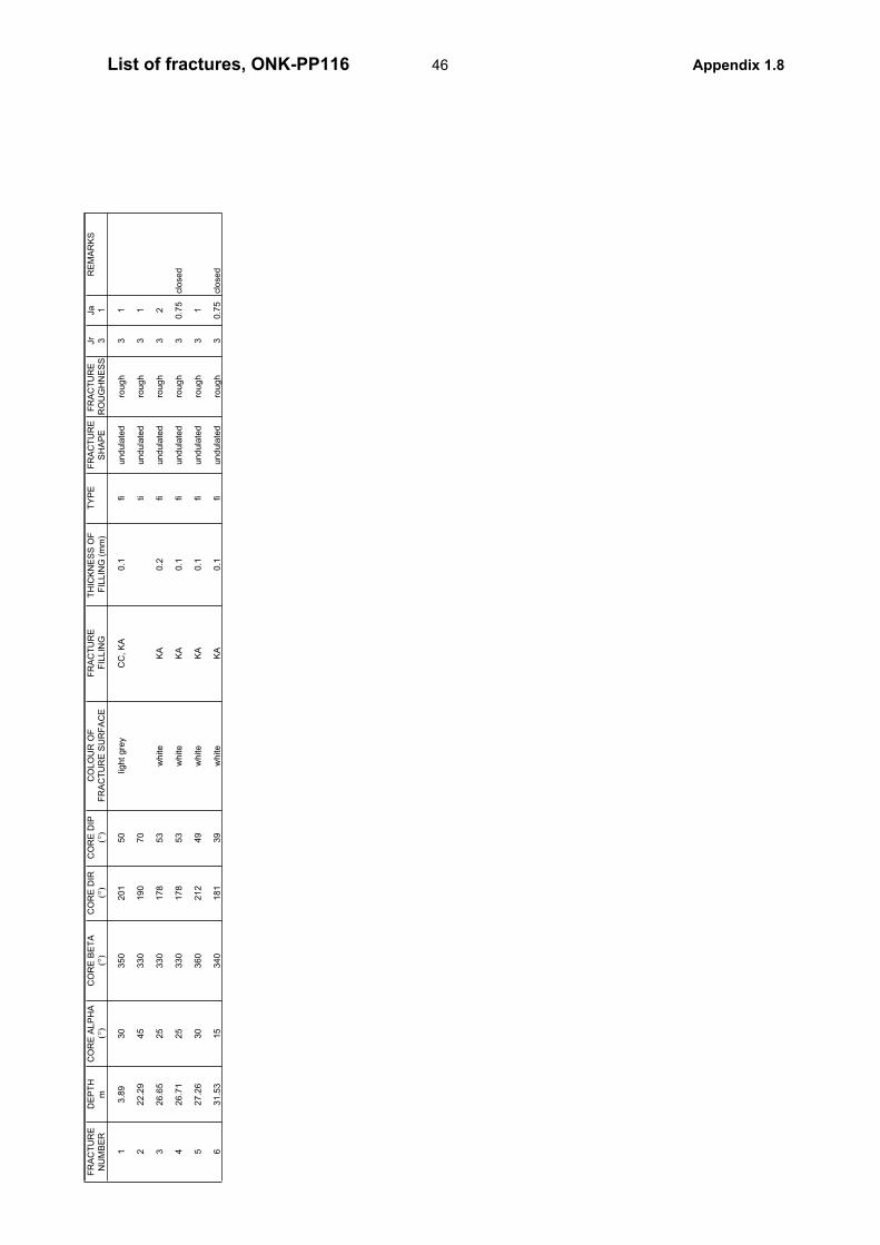
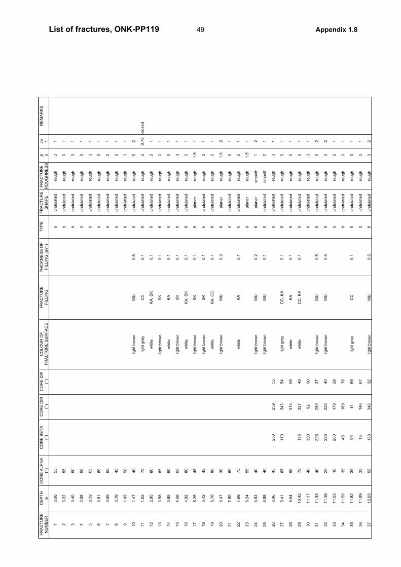
46List of fractures, ONK-PP116 Appendix 1.8
FR
AC
TU
RE
DE
PT
HC
OR
E A
LP
HA
CO
RE
BE
TA
CO
RE
DIR
CO
RE
DIP
CO
LO
UR
OF
FR
AC
TU
RE
TH
ICK
NE
SS
OF
T
YP
EF
RA
CT
UR
EF
RA
CT
UR
E
Jr
Ja
RE
MA
RK
S
NU
MB
ER
m(°
)(°
)(°
)(°
)F
RA
CT
UR
E S
UR
FA
CE
FIL
LIN
GF
ILLIN
G (
mm
)S
HA
PE
RO
UG
HN
ES
S3
1.5
10.6
525
tiundula
ted
rough
31
20.7
570
tiundula
ted
rough
31
30.7
940
light gre
yC
C0.1
fiundula
ted
rough
31
40.8
530
tipla
nar
rough
1.5
1part
ly c
losed
50.8
925
tiundula
ted
rough
30.7
5clo
sed
61.1
425
350
176
47
light gre
yC
C, M
U0.3
fiundula
ted
rough
32
71.3
110
90
90
87
light gre
yC
C0.1
fiundula
ted
rough
31
81.3
240
355
185
61
light gre
yC
C, S
K, C
U0.2
fiundula
ted
rough
32
91.4
040
130
63
47
light bro
wn
MU
, C
U0.1
fiundula
ted
rough
31
10
1.8
325
80
72
90
light bro
wn
MU
5fi
undula
ted
rough
32
11
6.2
230
335
163
56
tiundula
ted
rough
30.7
5clo
sed
12
6.3
990
light bro
wn
MU
10
fiundula
ted
rough
32
13
8.4
030
light bro
wn
MU
0.2
fiundula
ted
rough
30.7
5clo
sed
14
9.1
840
light gre
yC
C, M
U0.5
fiundula
ted
rough
32
15
10.0
130
light gre
yC
C0.1
fiundula
ted
rough
31
16
10.0
945
light gre
yC
C, M
U0.3
fiundula
ted
rough
32
17
10.2
545
tipla
nar
rough
1.5
1
18
10.4
445
tiundula
ted
rough
30.7
5clo
sed
19
12.0
735
70
239
86
light bro
wn
MU
0.2
fiundula
ted
rough
31
20
12.5
540
25
210
65
light bro
wn
MU
0.5
fiundula
ted
rough
32
21
12.6
955
345
180
77
light bro
wn
MU
0.2
fiundula
ted
rough
31
22
12.9
340
25
210
65
light bro
wn
SK
0.1
fiundula
ted
rough
31
23
13.7
245
350
181
66
tiundula
ted
rough
31
24
16.3
235
20
208
59
light gre
yC
C0.1
fipla
nar
rough
1.5
1
25
17.1
035
20
208
59
tiundula
ted
rough
31
26
17.8
213
95
88
81
light gre
yC
C, M
K0.2
fipla
nar
sm
ooth
12
27
18.1
920
45
239
60
tiundula
ted
rough
30.7
5clo
sed
28
18.2
630
70
244
84
tiundula
ted
rough
31
29
18.4
630
205
307
24
bla
ck
KL
0.2
fiundula
ted
sm
ooth
23
30
18.5
440
10
198
61
light gre
yC
C0.1
fiundula
ted
rough
31
31
18.9
840
25
210
65
light gre
yC
C0.1
fiundula
ted
sm
ooth
21
32
19.1
145
30
211
71
tiundula
ted
rough
30.7
5clo
sed
33
19.4
450
335
173
74
tiundula
ted
rough
31
34
20.0
435
35
220
65
light gre
yC
C0.1
fiundula
ted
rough
31
part
ly c
losed
35
20.7
235
5194
56
tiundula
ted
rough
30.7
5clo
sed
36
23.2
840
300
147
82
white
KA
0.1
fiundula
ted
rough
32
37
24.1
255
330
172
80
light gre
yC
C, K
A0.1
fiundula
ted
rough
31
38
24.2
440
350
180
61
light bro
wn
SK
0.1
fiundula
ted
rough
31
39
36.3
130
310
144
70
white
KA
0.1
fiundula
ted
rough
31
para
llel to
folia
tion, m
ostly c
losed
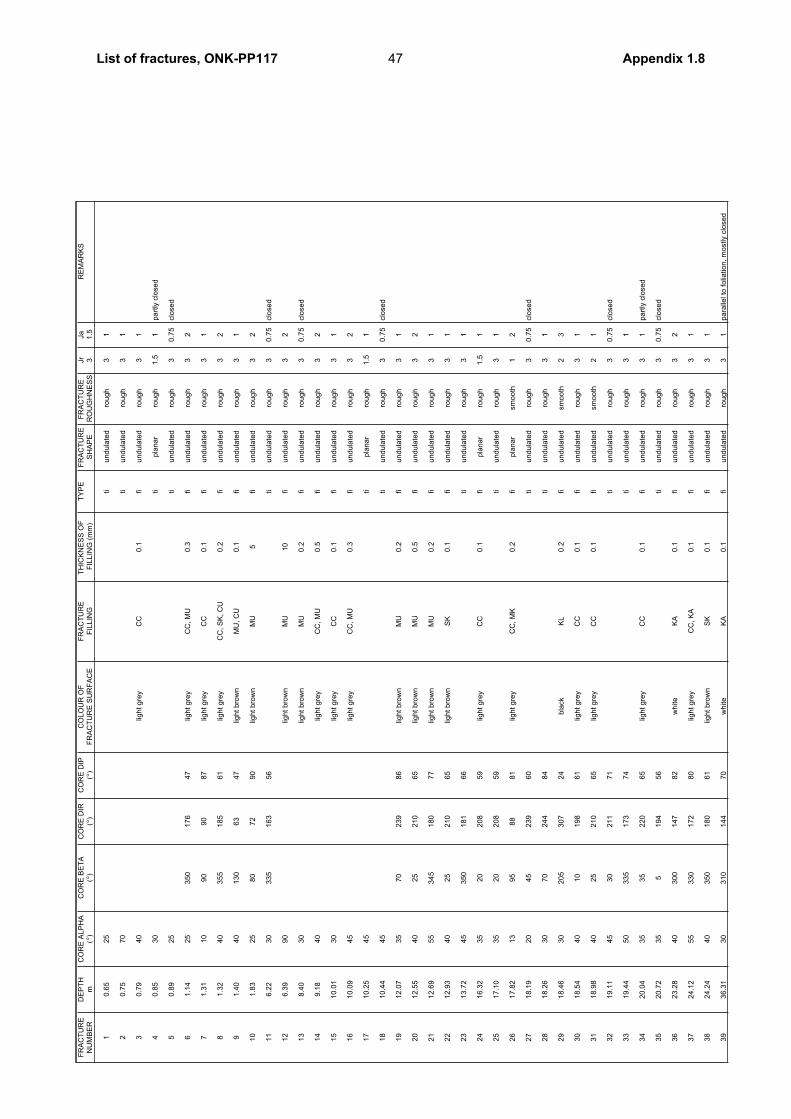
47List of fractures, ONK-PP117 Appendix 1.8
FR
AC
TU
RE
DE
PT
HC
OR
E A
LP
HA
CO
RE
BE
TA
CO
RE
DIR
CO
RE
DIP
CO
LO
UR
OF
FR
AC
TU
RE
TH
ICK
NE
SS
OF
T
YP
EF
RA
CT
UR
EF
RA
CT
UR
E
Jr
Ja
RE
MA
RK
S
NU
MB
ER
m(°
)(°
)(°
)(°
)F
RA
CT
UR
E S
UR
FA
CE
FIL
LIN
GF
ILL
ING
(m
m)
SH
AP
ER
OU
GH
NE
SS
31
10
.14
75
ligh
t b
row
nS
K0
.1fi
un
du
late
dro
ug
h3
1
20
.23
65
ligh
t b
row
nS
K0
.1fi
un
du
late
dro
ug
h3
1
31
.14
60
ligh
t b
row
nS
K0
.1fi
un
du
late
dro
ug
h3
1
41
.16
55
ligh
t b
row
nS
K0
.1fi
un
du
late
dro
ug
h3
1
51
.19
45
ligh
t b
row
nM
U0
.1fi
pla
na
rro
ug
h1
.51
61
.24
50
ligh
t b
row
nM
U0
.5fi
un
du
late
dro
ug
h3
2
72
.24
50
33
01
36
84
wh
ite
KA
0.1
fiu
nd
ula
ted
rou
gh
31
82
.67
75
16
53
40
46
tiu
nd
ula
ted
rou
gh
31
94
.37
25
34
51
39
57
wh
ite
KA
, S
K0
.3fi
un
du
late
dro
ug
h3
2
10
4.5
04
51
55
20
25
wh
ite
KA
0.1
fiu
nd
ula
ted
rou
gh
31
11
9.0
33
04
01
91
71
tip
lan
ar
rou
gh
1.5
1m
ostly c
lose
d
12
9.0
41
52
45
24
66
1ti
un
du
late
dro
ug
h3
1m
ostly c
lose
d
13
14
.88
75
26
53
18
60
ligh
t b
row
nS
K,
KA
0.1
fiu
nd
ula
ted
rou
gh
31
14
16
.94
40
27
02
81
71
ligh
t b
row
nS
K,
MU
0.1
fiu
nd
ula
ted
rou
gh
31
15
18
.22
40
32
51
28
77
ligh
t b
row
nS
K,
KA
0.1
fiu
nd
ula
ted
rou
gh
31
16
18
.79
50
40
17
98
7lig
ht
bro
wn
MU
0.2
fiu
nd
ula
ted
rou
gh
32
17
20
.62
40
30
17
87
5lig
ht
gre
yC
C0
.1fi
un
du
late
dro
ug
h3
1
18
21
.10
55
25
16
98
7ti
pla
na
rro
ug
h1
.51
19
23
.44
15
20
18
14
9ti
un
du
late
dro
ug
h3
0.7
5clo
se
d
20
23
.54
30
25
17
96
4w
hite
KA
0.1
fiu
nd
ula
ted
rou
gh
31
21
23
.76
25
20
17
65
8ti
un
du
late
dro
ug
h3
1
22
24
.63
60
13
08
45
tip
lan
ar
rou
gh
1.5
1
23
24
.85
30
36
01
55
60
ligh
t g
rey
CC
, K
A0
.3fi
un
du
late
dro
ug
h3
2
24
25
.13
70
33
03
25
78
wh
ite
KA
0.1
fiu
nd
ula
ted
rou
gh
31
25
25
.18
60
30
53
10
80
wh
ite
KA
0.1
fiu
nd
ula
ted
rou
gh
30
.75
clo
se
d
26
25
.50
45
51
59
75
wh
ite
KA
0.2
fip
lan
ar
rou
gh
1.5
2
27
25
.52
60
32
03
16
84
wh
ite
KA
0.1
fiu
nd
ula
ted
rou
gh
31
48List of fractures, ONK-PP118 Appendix 1.8
FR
AC
TU
RE
DE
PT
HC
OR
E A
LP
HA
CO
RE
BE
TA
CO
RE
DIR
CO
RE
DIP
CO
LO
UR
OF
FR
AC
TU
RE
TH
ICK
NE
SS
OF
T
YP
EF
RA
CT
UR
EF
RA
CT
UR
E
Jr
Ja
RE
MA
RK
S
NU
MB
ER
m(°
)(°
)(°
)(°
)F
RA
CT
UR
E S
UR
FA
CE
FIL
LIN
GF
ILL
ING
(m
m)
SH
AP
ER
OU
GH
NE
SS
31
10
.08
55
tiu
nd
ula
ted
rou
gh
31
20
.22
55
tiu
nd
ula
ted
rou
gh
31
30
.40
60
tiu
nd
ula
ted
rou
gh
31
40
.58
50
tiu
nd
ula
ted
rou
gh
31
50
.59
65
tiu
nd
ula
ted
rou
gh
31
60
.61
60
tiu
nd
ula
ted
rou
gh
31
70
.69
65
tiu
nd
ula
ted
rou
gh
31
80
.79
45
tiu
nd
ula
ted
rou
gh
31
91
.05
50
tiu
nd
ula
ted
rou
gh
31
10
1.4
74
0lig
ht
bro
wn
MU
0.5
fiu
nd
ula
ted
rou
gh
32
11
1.6
27
5lig
ht
gre
yC
C0
.1fi
un
du
late
dro
ug
h3
0.7
5clo
se
d
12
2.9
58
0w
hite
KA
, S
K0
.1fi
un
du
late
dro
ug
h3
1
13
3.5
88
5lig
ht
bro
wn
SK
0.1
fiu
nd
ula
ted
rou
gh
31
14
3.6
56
0w
hite
KA
0.1
fiu
nd
ula
ted
rou
gh
31
15
4.5
86
5lig
ht
bro
wn
SK
0.1
fiu
nd
ula
ted
rou
gh
31
16
4.9
28
0w
hite
KA
, S
K0
.1fi
un
du
late
dro
ug
h3
1
17
5.2
54
5lig
ht
bro
wn
SK
0.1
fip
lan
ar
rou
gh
1.5
1
18
5.4
24
5lig
ht
bro
wn
SK
0.1
fiu
nd
ula
ted
rou
gh
31
19
5.7
68
0w
hite
KA
, C
C0
.1fi
un
du
late
dro
ug
h3
1
20
6.4
73
0lig
ht
bro
wn
MU
0.3
fip
lan
ar
rou
gh
1.5
2
21
7.6
96
0ti
un
du
late
dro
ug
h3
1
22
7.9
97
5w
hite
KA
0.1
fiu
nd
ula
ted
rou
gh
31
23
8.2
45
5ti
pla
na
rro
ug
h1
.51
24
8.8
34
0lig
ht
bro
wn
MU
0.2
fip
lan
ar
sm
oo
th1
2
25
8.8
84
0lig
ht
bro
wn
MU
0.1
fiu
nd
ula
ted
sm
oo
th2
1
26
8.9
64
52
50
25
95
5ti
un
du
late
dro
ug
h3
1
27
9.4
16
51
10
34
35
4lig
ht
gre
yC
C,
KA
0.1
fiu
nd
ula
ted
rou
gh
31
28
9.5
49
03
13
59
wh
ite
KA
0.1
fiu
nd
ula
ted
rou
gh
31
29
10
.42
75
13
53
27
49
wh
ite
CC
, K
A0
.1fi
un
du
late
dro
ug
h3
1
30
11
.17
40
30
09
29
0ti
un
du
late
dro
ug
h3
1
31
11
.33
40
22
52
50
37
ligh
t b
row
nM
U0
.5fi
un
du
late
dro
ug
h3
2
32
11
.38
25
22
52
26
40
ligh
t b
row
nM
U0
.5fi
un
du
late
dro
ug
h3
2
33
11
.53
10
20
01
79
28
tiu
nd
ula
ted
rou
gh
31
34
11
.59
35
45
16
97
8ti
un
du
late
dro
ug
h3
1
35
11
.82
35
95
14
69
ligh
t g
rey
CC
0.1
fiu
nd
ula
ted
rou
gh
31
36
11
.89
35
15
14
66
7ti
un
du
late
dro
ug
h3
1
37
12
.03
55
15
03
46
32
ligh
t b
row
nM
U0
.5fi
un
du
late
dro
ug
h3
2
49List of fractures, ONK-PP119 Appendix 1.8
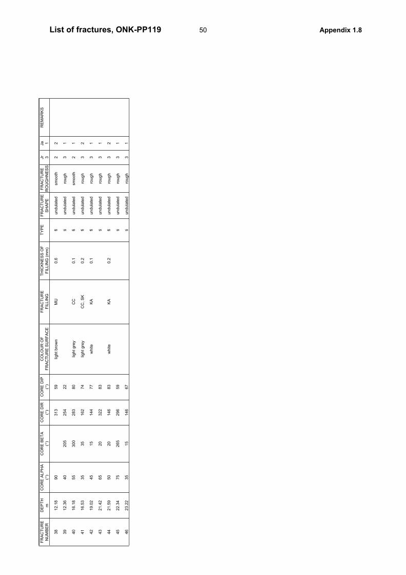
FR
AC
TU
RE
DE
PT
HC
OR
E A
LP
HA
CO
RE
BE
TA
CO
RE
DIR
CO
RE
DIP
CO
LO
UR
OF
FR
AC
TU
RE
TH
ICK
NE
SS
OF
T
YP
EF
RA
CT
UR
EF
RA
CT
UR
E
Jr
Ja
RE
MA
RK
S
NU
MB
ER
m(°
)(°
)(°
)(°
)F
RA
CT
UR
E S
UR
FA
CE
FIL
LIN
GF
ILL
ING
(m
m)
SH
AP
ER
OU
GH
NE
SS
31
38
12
.18
90
31
35
9lig
ht
bro
wn
MU
0.6
fiu
nd
ula
ted
sm
oo
th2
2
39
12
.36
40
20
52
54
22
tiu
nd
ula
ted
rou
gh
31
40
16
.18
55
30
02
83
80
ligh
t g
rey
CC
0.1
fiu
nd
ula
ted
sm
oo
th2
1
41
16
.53
35
35
16
27
4lig
ht
gre
yC
C,
SK
0.2
fiu
nd
ula
ted
rou
gh
32
42
19
.02
45
15
14
47
7w
hite
KA
0.1
fiu
nd
ula
ted
rou
gh
31
43
21
.42
65
20
32
28
3ti
un
du
late
dro
ug
h3
1
44
21
.59
50
20
14
68
3w
hite
KA
0.2
fiu
nd
ula
ted
rou
gh
32
45
22
.34
75
26
52
96
59
tiu
nd
ula
ted
rou
gh
31
46
23
.22
35
15
14
66
7ti
un
du
late
dro
ug
h3
1
50List of fractures, ONK-PP119 Appendix 1.8
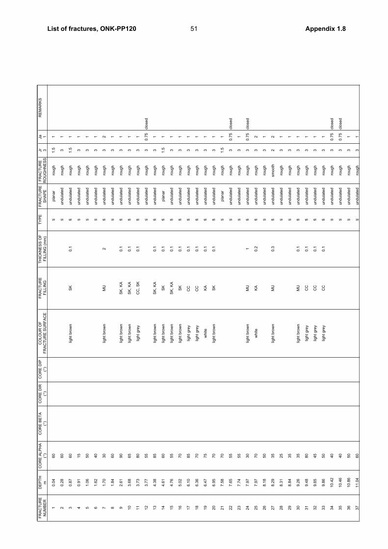
FR
AC
TU
RE
DE
PT
HC
OR
E A
LP
HA
CO
RE
BE
TA
CO
RE
DIR
CO
RE
DIP
CO
LO
UR
OF
FR
AC
TU
RE
TH
ICK
NE
SS
OF
T
YP
EF
RA
CT
UR
EF
RA
CT
UR
E
Jr
Ja
RE
MA
RK
S
NU
MB
ER
m(°
)(°
)(°
)(°
)F
RA
CT
UR
E S
UR
FA
CE
FIL
LIN
GF
ILL
ING
(m
m)
SH
AP
ER
OU
GH
NE
SS
31
10
.04
60
tip
lan
ar
rou
gh
1.5
1
20
.28
60
tiu
nd
ula
ted
rou
gh
31
30
.87
60
ligh
t b
row
nS
K0
.1fi
un
du
late
dro
ug
h1
.51
40
.91
15
tiu
nd
ula
ted
rou
gh
31
51
.06
50
tiu
nd
ula
ted
rou
gh
31
61
.62
40
tiu
nd
ula
ted
rou
gh
31
71
.70
30
ligh
t b
row
nM
U2
fiu
nd
ula
ted
rou
gh
32
81
.84
60
tiu
nd
ula
ted
rou
gh
31
92
.61
90
ligh
t b
row
nS
K,
KA
0.1
fiu
nd
ula
ted
rou
gh
31
10
3.6
86
5lig
ht
bro
wn
SK
, K
A0
.1fi
un
du
late
dro
ug
h3
1
11
3.7
38
0lig
ht
gre
yC
C,
SK
0.1
fiu
nd
ula
ted
rou
gh
31
12
3.7
75
5ti
un
du
late
dro
ug
h3
0.7
5clo
se
d
13
4.3
88
5lig
ht
bro
wn
SK
, K
A0
.1fi
un
du
late
dro
ug
h3
1
14
4.6
16
0lig
ht
bro
wn
SK
0.1
fip
lan
ar
rou
gh
1.5
1
15
4.7
65
5lig
ht
bro
wn
SK
, K
A0
.1fi
un
du
late
dro
ug
h3
1
16
5.0
27
0lig
ht
bro
wn
SK
0.1
fiu
nd
ula
ted
rou
gh
31
17
6.1
08
5lig
ht
gre
yC
C
0.1
fiu
nd
ula
ted
rou
gh
31
18
6.3
67
0lig
ht
gre
yC
C
0.1
fiu
nd
ula
ted
rou
gh
31
19
6.4
77
5w
hite
KA
0.1
fiu
nd
ula
ted
rou
gh
31
20
6.9
57
0lig
ht
bro
wn
SK
0.1
fiu
nd
ula
ted
rou
gh
31
21
7.5
87
0ti
pla
na
rro
ug
h1
.51
22
7.6
55
5ti
un
du
late
dro
ug
h3
0.7
5clo
se
d
23
7.7
45
5ti
un
du
late
dro
ug
h3
1
24
7.9
73
0lig
ht
bro
wn
MU
1fi
un
du
late
dro
ug
h3
0.7
5clo
se
d
25
7.9
77
0w
hite
KA
0.2
fiu
nd
ula
ted
rou
gh
32
26
8.1
85
0ti
un
du
late
dro
ug
h3
1
27
8.2
93
5lig
ht
bro
wn
MU
0.3
fiu
nd
ula
ted
sm
oo
th2
2
28
8.3
12
5ti
un
du
late
dro
ug
h3
1
29
8.8
43
5ti
un
du
late
dro
ug
h3
1
30
9.2
63
5lig
ht
bro
wn
MU
0.1
fiu
nd
ula
ted
rou
gh
31
31
9.4
88
0lig
ht
gre
yC
C0
.1fi
un
du
late
dro
ug
h3
1
32
9.6
54
5lig
ht
gre
yC
C0
.1fi
un
du
late
dro
ug
h3
1
33
9.8
65
0lig
ht
gre
yC
C0
.1fi
un
du
late
dro
ug
h3
1
34
10
.42
40
tiu
nd
ula
ted
rou
gh
30
.75
clo
se
d
35
10
.46
40
tiu
nd
ula
ted
rou
gh
30
.75
clo
se
d
36
10
.86
50
tiu
nd
ula
ted
rou
gh
31
37
11
.04
60
tiu
nd
ula
ted
rou
gh
31
51List of fractures, ONK-PP120 Appendix 1.8
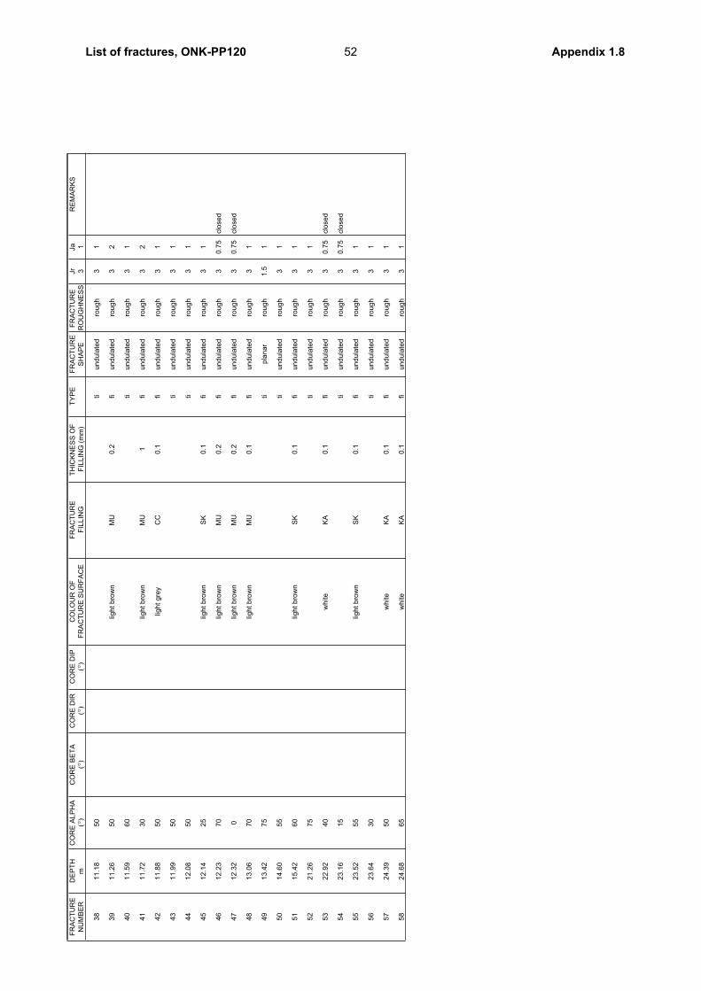
FR
AC
TU
RE
DE
PT
HC
OR
E A
LP
HA
CO
RE
BE
TA
CO
RE
DIR
CO
RE
DIP
CO
LO
UR
OF
FR
AC
TU
RE
TH
ICK
NE
SS
OF
T
YP
EF
RA
CT
UR
EF
RA
CT
UR
E
Jr
Ja
RE
MA
RK
S
NU
MB
ER
m(°
)(°
)(°
)(°
)F
RA
CT
UR
E S
UR
FA
CE
FIL
LIN
GF
ILL
ING
(m
m)
SH
AP
ER
OU
GH
NE
SS
31
38
11
.18
50
tiu
nd
ula
ted
rou
gh
31
39
11
.26
50
ligh
t b
row
nM
U0
.2fi
un
du
late
dro
ug
h3
2
40
11
.59
60
tiu
nd
ula
ted
rou
gh
31
41
11
.72
30
ligh
t b
row
nM
U1
fiu
nd
ula
ted
rou
gh
32
42
11
.88
50
ligh
t g
rey
CC
0.1
fiu
nd
ula
ted
rou
gh
31
43
11
.99
50
tiu
nd
ula
ted
rou
gh
31
44
12
.08
50
tiu
nd
ula
ted
rou
gh
31
45
12
.14
25
ligh
t b
row
nS
K0
.1fi
un
du
late
dro
ug
h3
1
46
12
.23
70
ligh
t b
row
nM
U0
.2fi
un
du
late
dro
ug
h3
0.7
5clo
se
d
47
12
.32
0lig
ht
bro
wn
MU
0.2
fiu
nd
ula
ted
rou
gh
30
.75
clo
se
d
48
13
.06
70
ligh
t b
row
nM
U0
.1fi
un
du
late
dro
ug
h3
1
49
13
.42
75
tip
lan
ar
rou
gh
1.5
1
50
14
.60
55
tiu
nd
ula
ted
rou
gh
31
51
15
.42
60
ligh
t b
row
nS
K0
.1fi
un
du
late
dro
ug
h3
1
52
21
.26
75
tiu
nd
ula
ted
rou
gh
31
53
22
.92
40
wh
ite
KA
0.1
fiu
nd
ula
ted
rou
gh
30
.75
clo
se
d
54
23
.16
15
tiu
nd
ula
ted
rou
gh
30
.75
clo
se
d
55
23
.52
55
ligh
t b
row
nS
K0
.1fi
un
du
late
dro
ug
h3
1
56
23
.64
30
tiu
nd
ula
ted
rou
gh
31
57
24
.39
50
wh
ite
KA
0.1
fiu
nd
ula
ted
rou
gh
31
58
24
.68
65
wh
ite
KA
0.1
fiu
nd
ula
ted
rou
gh
31
52List of fractures, ONK-PP120 Appendix 1.8
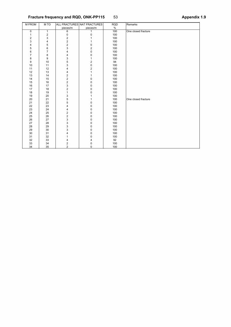
M FROM M TO ALL FRACTURES NAT FRACTURES RQD Remarks
pieces/m pieces/m %
0 1 6 1 100 One closed fracture
1 2 0 0 100
2 3 2 1 100
3 4 2 1 100
4 5 2 0 100
5 6 3 2 100
6 7 4 0 100
7 8 4 0 100
8 9 3 1 100
9 10 5 2 94
10 11 3 0 100
11 12 4 2 100
12 13 4 1 100
13 14 2 1 100
14 15 2 0 100
15 16 2 0 100
16 17 3 0 100
17 18 2 0 100
18 19 1 0 100
19 20 3 1 100
20 21 5 1 100 One closed fracture
21 22 5 0 100
22 23 4 0 100
23 24 4 0 100
24 25 2 0 100
25 26 2 0 100
26 27 3 0 100
27 28 3 0 100
28 29 3 0 100
29 30 3 0 100
30 31 4 0 100
31 32 1 0 100
32 33 4 4 92
33 34 2 0 100
34 35 2 0 100
53Fracture frequency and RQD, ONK-PP115 Appendix 1.9
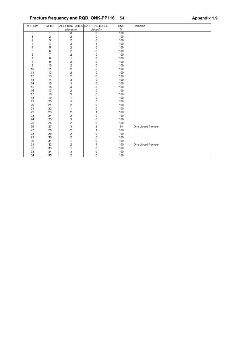
M FROM M TO ALL FRACTURES NAT FRACTURES RQD Remarks
pieces/m pieces/m %
0 1 3 0 100
1 2 2 0 100
2 3 2 0 100
3 4 3 1 100
4 5 2 0 100
5 6 2 0 100
6 7 2 0 100
7 8 1 0 100
8 9 2 0 100
9 10 2 0 100
10 11 2 0 100
11 12 2 0 100
12 13 2 0 100
13 14 3 0 100
14 15 3 0 100
15 16 4 0 100
16 17 2 0 100
17 18 3 0 100
18 19 1 0 100
19 20 5 0 100
20 21 2 0 100
21 22 1 0 100
22 23 2 1 100
23 24 2 0 100
24 25 3 0 100
25 26 2 0 100
26 27 3 2 94 One closed fracture
27 28 2 1 100
28 29 2 0 100
29 30 2 0 100
30 31 1 0 100
31 32 2 1 100 One closed fracture
32 33 1 0 100
33 34 3 0 100
34 35 2 0 100
54Fracture frequency and RQD, ONK-PP116 Appendix 1.9
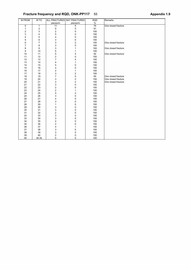
M FROM M TO ALL FRACTURES NAT FRACTURES RQD Remarks
pieces/m pieces/m %
0 1 11 5 76 One closed fracture
1 2 9 5 91
2 3 2 0 100
3 4 5 0 100
4 5 4 0 100
5 6 3 0 100
6 7 3 2 100 One closed fracture
7 8 3 0 100
8 9 3 1 100 One closed fracture
9 10 5 1 100
10 11 5 4 92 One closed fracture
11 12 2 0 100
12 13 7 4 100
13 14 4 1 100
14 15 5 0 100
15 16 4 0 100
16 17 2 1 100
17 18 3 2 100
18 19 7 5 85 One closed fracture
19 20 3 2 100 One closed fracture
20 21 3 2 100 One closed fracture
21 22 3 0 100
22 23 2 0 100
23 24 2 1 100
24 25 5 2 100
25 26 3 0 100
26 27 4 0 100
27 28 3 0 100
28 29 1 0 100
29 30 3 0 100
30 31 3 0 100
31 32 2 0 100
32 33 3 0 100
33 34 3 0 100
34 35 2 0 100
35 36 2 0 100
36 37 4 1 100
37 38 3 0 100
38 39 3 0 100
39 40 2 0 100
40 40.35 0 0 100
55Fracture frequency and RQD, ONK-PP117 Appendix 1.9
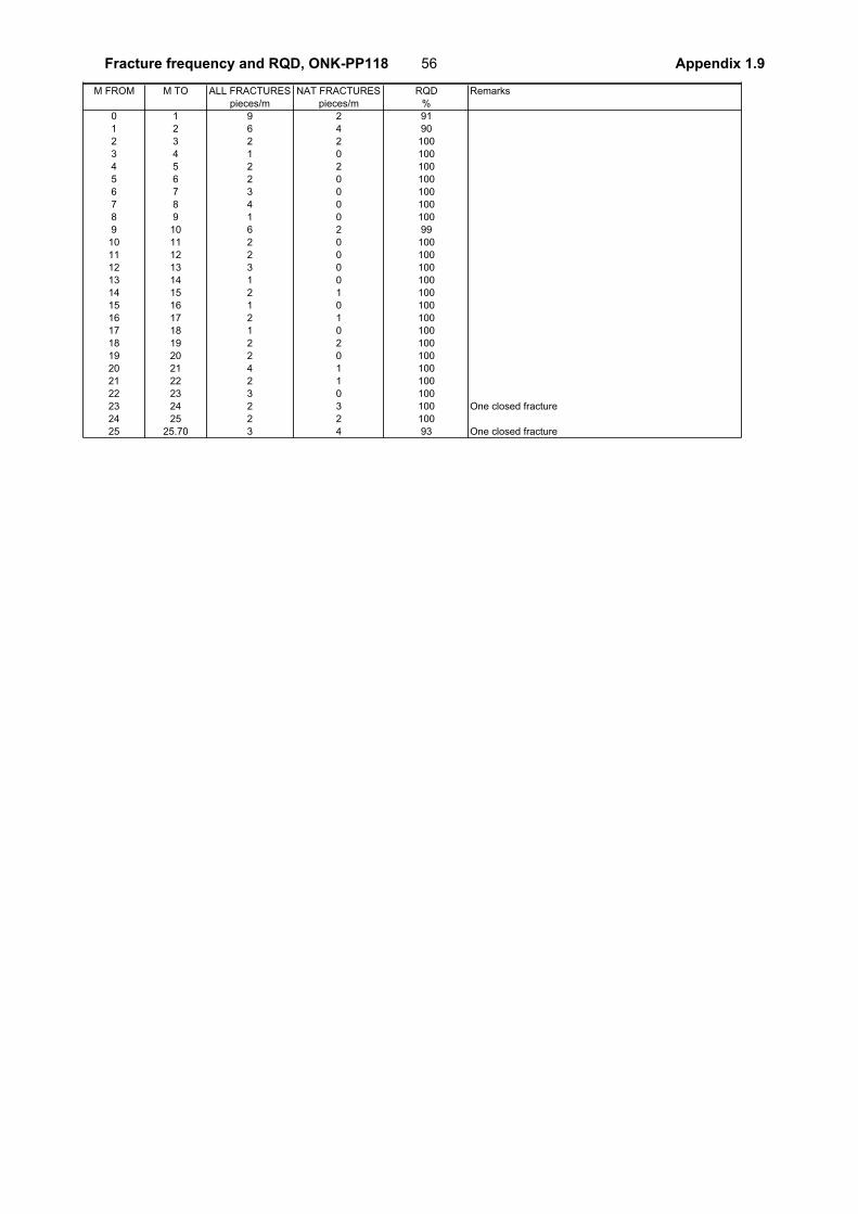
M FROM M TO ALL FRACTURES NAT FRACTURES RQD Remarks
pieces/m pieces/m %
0 1 9 2 91
1 2 6 4 90
2 3 2 2 100
3 4 1 0 100
4 5 2 2 100
5 6 2 0 100
6 7 3 0 100
7 8 4 0 100
8 9 1 0 100
9 10 6 2 99
10 11 2 0 100
11 12 2 0 100
12 13 3 0 100
13 14 1 0 100
14 15 2 1 100
15 16 1 0 100
16 17 2 1 100
17 18 1 0 100
18 19 2 2 100
19 20 2 0 100
20 21 4 1 100
21 22 2 1 100
22 23 3 0 100
23 24 2 3 100 One closed fracture
24 25 2 2 100
25 25.70 3 4 93 One closed fracture
56Fracture frequency and RQD, ONK-PP118 Appendix 1.9
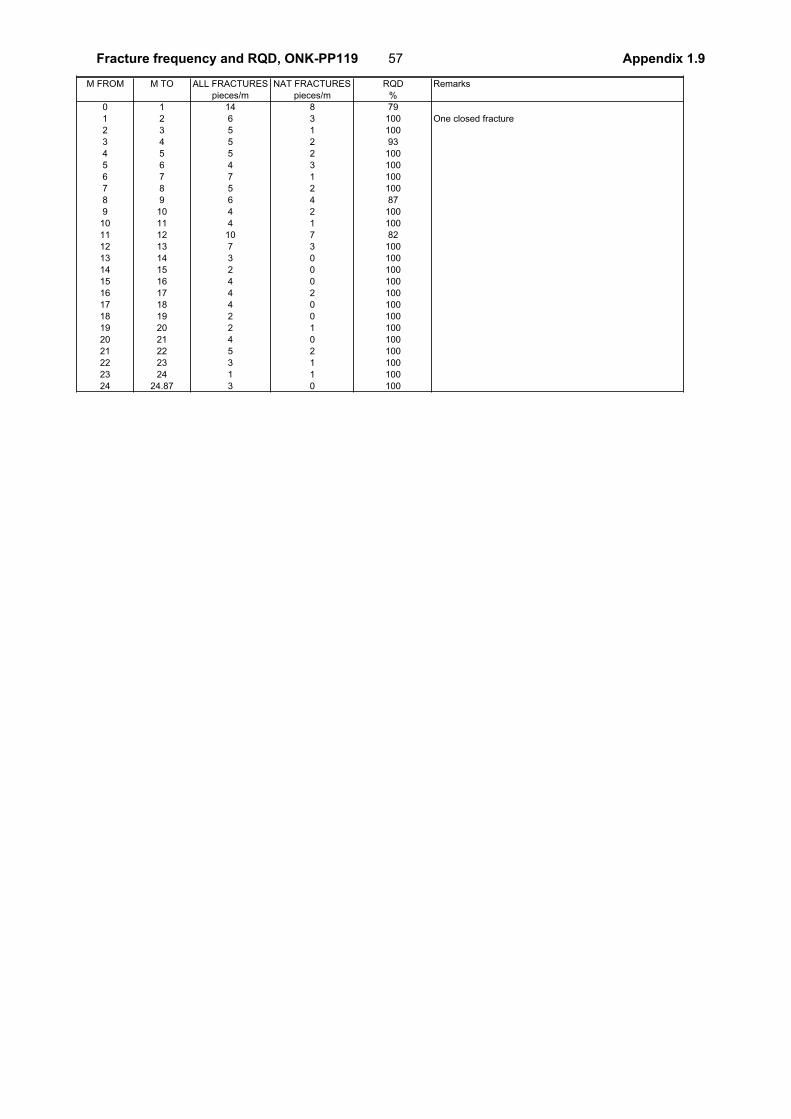
M FROM M TO ALL FRACTURES NAT FRACTURES RQD Remarks
pieces/m pieces/m %
0 1 14 8 79
1 2 6 3 100 One closed fracture
2 3 5 1 100
3 4 5 2 93
4 5 5 2 100
5 6 4 3 100
6 7 7 1 100
7 8 5 2 100
8 9 6 4 87
9 10 4 2 100
10 11 4 1 100
11 12 10 7 82
12 13 7 3 100
13 14 3 0 100
14 15 2 0 100
15 16 4 0 100
16 17 4 2 100
17 18 4 0 100
18 19 2 0 100
19 20 2 1 100
20 21 4 0 100
21 22 5 2 100
22 23 3 1 100
23 24 1 1 100
24 24.87 3 0 100
57Fracture frequency and RQD, ONK-PP119 Appendix 1.9
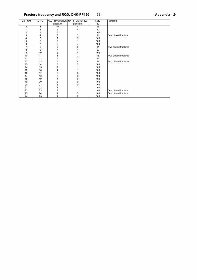
M FROM M TO ALL FRACTURES NAT FRACTURES RQD Remarks
pieces/m pieces/m %
0 1 10 4 96
1 2 6 4 92
2 3 6 1 100
3 4 8 3 91 One closed fracture
4 5 7 3 100
5 6 3 1 100
6 7 5 4 100
7 8 8 5 84 Two closed fractures
8 9 7 4 98
9 10 8 4 100
10 11 6 3 96 Two closed fractures
11 12 9 7 91
12 13 6 4 68 Two closed fractures
13 14 3 2 100
14 15 2 1 100
15 16 4 1 100
16 17 2 0 100
17 18 2 0 100
18 19 4 0 100
19 20 2 0 100
20 21 3 0 100
21 22 3 1 100
22 23 3 1 100 One closed fracture
23 24 4 3 100 One closed fracture
24 25 4 2 100
58Fracture frequency and RQD, ONK-PP120 Appendix 1.9
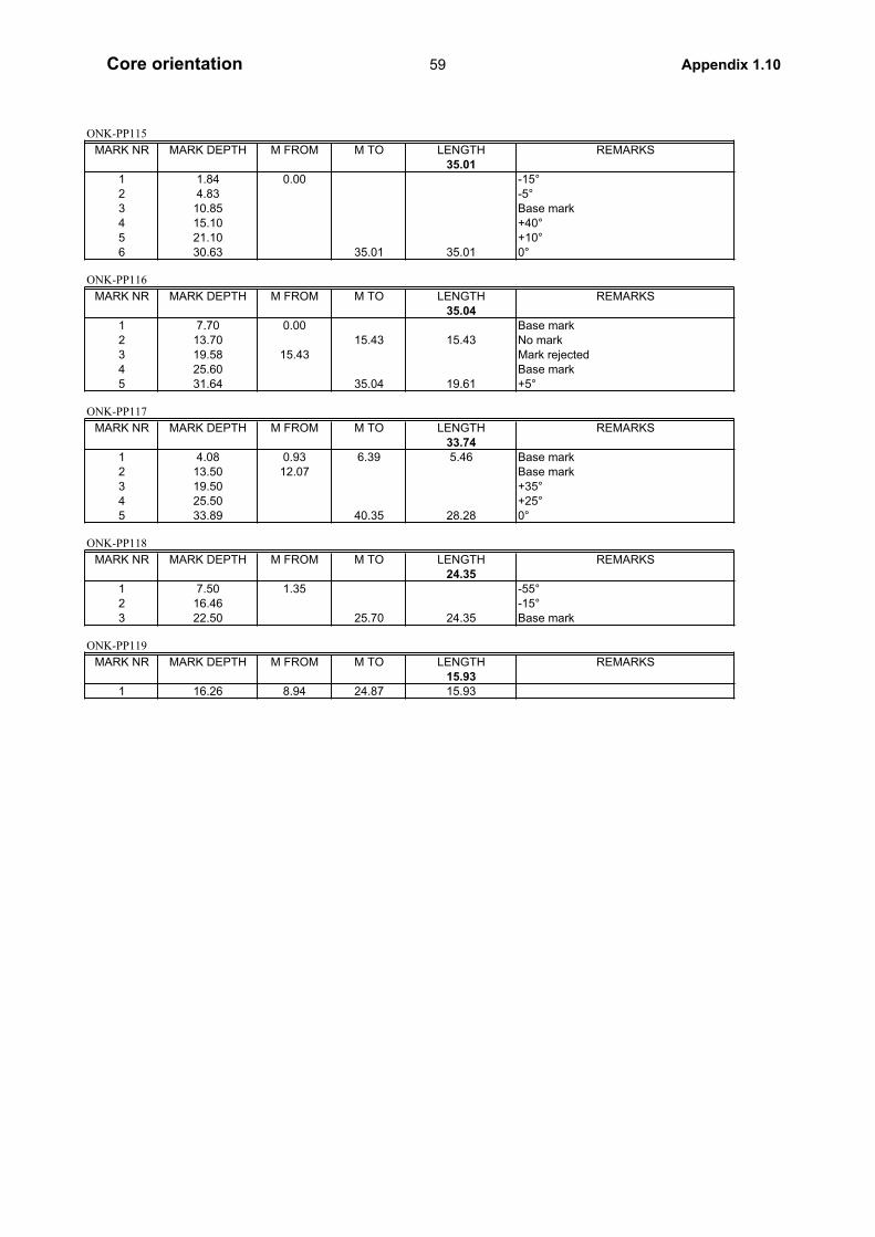
ONK-PP115
MARK NR MARK DEPTH M FROM M TO LENGTH REMARKS
35.011 1.84 0.00 -15°
2 4.83 -5°
3 10.85 Base mark
4 15.10 +40°
5 21.10 +10°
6 30.63 35.01 35.01 0°
ONK-PP116
MARK NR MARK DEPTH M FROM M TO LENGTH REMARKS
35.041 7.70 0.00 Base mark
2 13.70 15.43 15.43 No mark
3 19.58 15.43 Mark rejected
4 25.60 Base mark
5 31.64 35.04 19.61 +5°
ONK-PP117
MARK NR MARK DEPTH M FROM M TO LENGTH REMARKS
33.741 4.08 0.93 6.39 5.46 Base mark
2 13.50 12.07 Base mark
3 19.50 +35°
4 25.50 +25°
5 33.89 40.35 28.28 0°
ONK-PP118
MARK NR MARK DEPTH M FROM M TO LENGTH REMARKS
24.351 7.50 1.35 -55°
2 16.46 -15°
3 22.50 25.70 24.35 Base mark
ONK-PP119
MARK NR MARK DEPTH M FROM M TO LENGTH REMARKS
15.931 16.26 8.94 24.87 15.93
59Core orientation Appendix 1.10

60
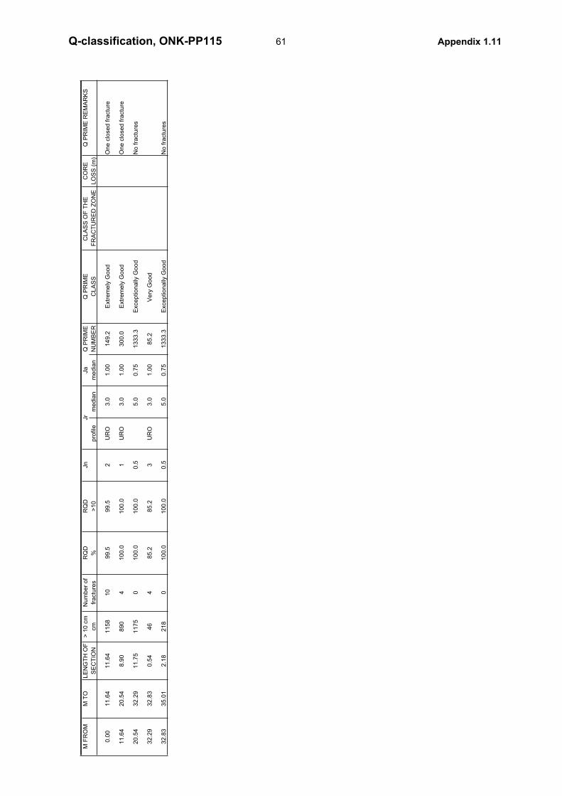
M F
RO
MM
TO
LE
NG
TH
OF
> 1
0 c
mN
um
be
r o
fR
QD
RQ
DJn
Q P
RIM
EQ
PR
IME
CL
AS
S O
F T
HE
C
OR
EQ
PR
IME
RE
MA
RK
S
SE
CT
ION
cm
fra
ctu
res
%>
10
pro
file
me
dia
nm
ed
ian
NU
MB
ER
CL
AS
SF
RA
CT
UR
ED
ZO
NE
LO
SS
(m
)
0.0
01
1.6
41
1.6
41
15
81
09
9.5
99
.52
UR
O3
.01
.00
14
9.2
Extr
em
ely
Go
od
On
e c
lose
d f
ractu
re
11
.64
20
.54
8.9
08
90
41
00
.01
00
.01
UR
O3
.01
.00
30
0.0
Extr
em
ely
Go
od
On
e c
lose
d f
ractu
re
20
.54
32
.29
11
.75
11
75
01
00
.01
00
.00
.55
.00
.75
13
33
.3E
xce
ptio
na
lly G
oo
dN
o f
ractu
res
32
.29
32
.83
0.5
44
64
85
.28
5.2
3U
RO
3.0
1.0
08
5.2
Ve
ry G
oo
d
32
.83
35
.01
2.1
82
18
01
00
.01
00
.00
.55
.00
.75
13
33
.3E
xce
ptio
na
lly G
oo
dN
o f
ractu
res
Jr
Ja
61Q-classification, ONK-PP115 Appendix 1.11
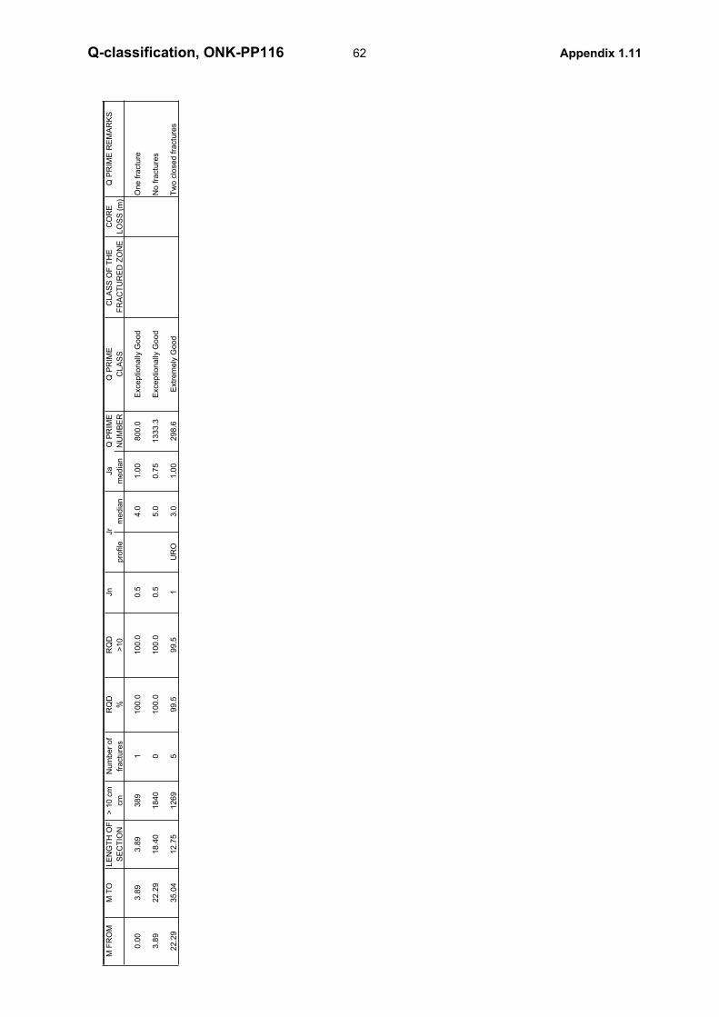
M F
RO
MM
TO
LE
NG
TH
OF
> 1
0 c
mN
um
be
r o
fR
QD
RQ
DJn
Q P
RIM
EQ
PR
IME
CL
AS
S O
F T
HE
C
OR
EQ
PR
IME
RE
MA
RK
S
SE
CT
ION
cm
fra
ctu
res
%>
10
pro
file
me
dia
nm
ed
ian
NU
MB
ER
CL
AS
SF
RA
CT
UR
ED
ZO
NE
LO
SS
(m
)
0.0
03
.89
3.8
93
89
11
00
.01
00
.00
.54
.01
.00
80
0.0
Exce
ptio
na
lly G
oo
dO
ne
fra
ctu
re
3.8
92
2.2
91
8.4
01
84
00
10
0.0
10
0.0
0.5
5.0
0.7
51
33
3.3
Exce
ptio
na
lly G
oo
dN
o f
ractu
res
22
.29
35
.04
12
.75
12
69
59
9.5
99
.51
UR
O3
.01
.00
29
8.6
Extr
em
ely
Go
od
Tw
o c
lose
d f
ractu
res
Jr
Ja
62Q-classification, ONK-PP116 Appendix 1.11
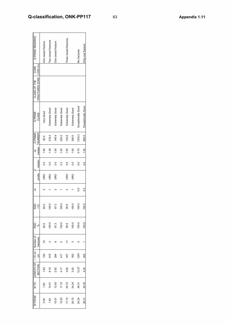
M F
RO
MM
TO
LE
NG
TH
OF
> 1
0 c
mN
um
be
r o
fR
QD
RQ
DJn
Q P
RIM
EQ
PR
IME
CL
AS
S O
F T
HE
C
OR
EQ
PR
IME
RE
MA
RK
S
SE
CT
ION
cm
fra
ctu
res
%>
10
pro
file
me
dia
nm
ed
ian
NU
MB
ER
CL
AS
SF
RA
CT
UR
ED
ZO
NE
LO
SS
(m
)
0.0
01
.83
1.8
31
50
10
82
.08
2.0
3U
RO
3.0
1.0
08
2.0
Ve
ry G
oo
d
On
e c
lose
d f
ractu
re
1.8
31
0.0
18
.18
81
84
10
0.0
10
0.0
1U
RO
3.0
1.3
82
18
.2E
xtr
em
ely
Go
od
Tw
o c
lose
d f
ractu
res
10
.01
12
.93
2.9
22
84
89
7.3
97
.32
UR
O3
.01
.00
14
5.9
Extr
em
ely
Go
od
On
e c
lose
d f
ractu
re
12
.93
17
.10
4.1
74
17
21
00
.01
00
.01
2.3
1.0
02
25
.0E
xtr
em
ely
Go
od
17
.10
20
.72
3.6
23
47
11
95
.99
5.9
2U
RO
3.0
1.0
01
43
.8E
xtr
em
ely
Go
od
Th
ree
clo
se
d f
ractu
res
20
.72
24
.24
3.5
23
52
31
00
.01
00
.01
UR
O3
.01
.00
30
0.0
Extr
em
ely
Go
od
24
.24
36
.31
12
.07
12
07
01
00
.01
00
.00
.55
.00
.75
13
33
.3E
xce
ptio
na
lly G
oo
dN
o f
ractu
res
36
.31
40
.35
4.0
44
04
11
00
.01
00
.00
.54
.01
.00
80
0.0
Exce
ptio
na
lly G
oo
dO
nly
on
e f
ractu
re
Jr
Ja
63Q-classification, ONK-PP117 Appendix 1.11
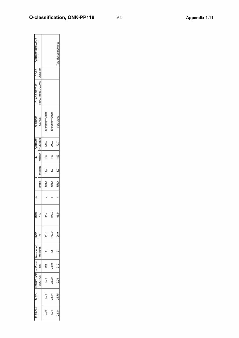
M F
RO
MM
TO
LE
NG
TH
OF
> 1
0 c
mN
um
be
r o
fR
QD
RQ
DJn
Q P
RIM
EQ
PR
IME
CL
AS
S O
F T
HE
C
OR
EQ
PR
IME
RE
MA
RK
S
SE
CT
ION
cm
fra
ctu
res
%>
10
pro
file
me
dia
nm
ed
ian
NU
MB
ER
CL
AS
SF
RA
CT
UR
ED
ZO
NE
LO
SS
(m
)
0.0
01
.24
1.2
41
05
68
4.7
84
.72
UR
O3
.01
.00
12
7.0
Extr
em
ely
Go
od
1.2
42
3.4
42
2.2
02
21
91
21
00
.01
00
.01
UR
O3
.01
.00
29
9.9
Extr
em
ely
Go
od
23
.44
25
.70
2.2
62
19
99
6.9
96
.94
UR
O3
.01
.00
72
.7V
ery
Go
od
T
wo
clo
se
d f
ractu
res
Jr
Ja
64Q-classification, ONK-PP118 Appendix 1.11
M F
RO
MM
TO
LE
NG
TH
OF
> 1
0 c
mN
um
be
r o
fR
QD
RQ
DJn
Q P
RIM
EQ
PR
IME
CL
AS
S O
F T
HE
C
OR
EQ
PR
IME
RE
MA
RK
S
SE
CT
ION
cm
fra
ctu
res
%>
10
pro
file
me
dia
nm
ed
ian
NU
MB
ER
CL
AS
SF
RA
CT
UR
ED
ZO
NE
LO
SS
(m
)
0.0
01
.62
1.6
21
41
11
87
.08
7.0
4U
RO
3.0
1.0
06
5.3
Ve
ry G
oo
d
Mo
stly t
igh
t fr
actu
res
1.6
21
1.1
79
.55
93
51
89
7.9
97
.93
UR
O3
.01
.00
97
.9V
ery
Go
od
11
.17
12
.36
1.1
91
01
10
84
.98
4.9
3U
RO
3.0
1.0
08
4.9
Ve
ry G
oo
d
12
.36
24
.87
12
.51
12
51
71
00
.01
00
.01
UR
O3
.01
.00
30
0.0
Extr
em
ely
Go
od
Jr
Ja
65Q-classification, ONK-PP119 Appendix 1.11
M F
RO
MM
TO
LE
NG
TH
OF
> 1
0 c
mN
um
be
r o
fR
QD
RQ
DJn
Q P
RIM
EQ
PR
IME
CL
AS
S O
F T
HE
C
OR
EQ
PR
IME
RE
MA
RK
S
SE
CT
ION
cm
fra
ctu
res
%>
10
pro
file
me
dia
nm
ed
ian
NU
MB
ER
CL
AS
SF
RA
CT
UR
ED
ZO
NE
LO
SS
(m
)
0.0
07
.58
7.5
87
37
20
97
.29
7.2
3U
RO
3.0
1.0
09
7.2
Ve
ry G
oo
d
On
e c
lose
d f
ractu
re
7.5
81
2.3
24
.74
41
12
78
6.7
86
.74
UR
O3
.01
.00
65
.0V
ery
Go
od
S
ix c
lose
d f
ractu
res
12
.32
15
.42
3.1
03
10
41
00
.01
00
.01
UR
O3
.01
.00
30
0.0
Extr
em
ely
Go
od
15
.42
21
.26
5.8
45
84
01
00
.01
00
.00
.55
.00
.75
13
33
.3E
xce
ptio
na
lly G
oo
dN
o f
ractu
res
21
.26
25
.00
3.7
43
74
71
00
.01
00
.02
UR
O3
.01
.00
15
0.0
Extr
em
ely
Go
od
Tw
o c
lose
d f
ractu
res
Jr
Ja
66Q-classification, ONK-PP120 Appendix 1.11
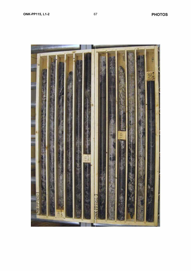
67ONK-PP115, L1-2 PHOTOS
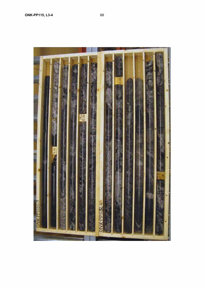
68ONK-PP115, L3-4
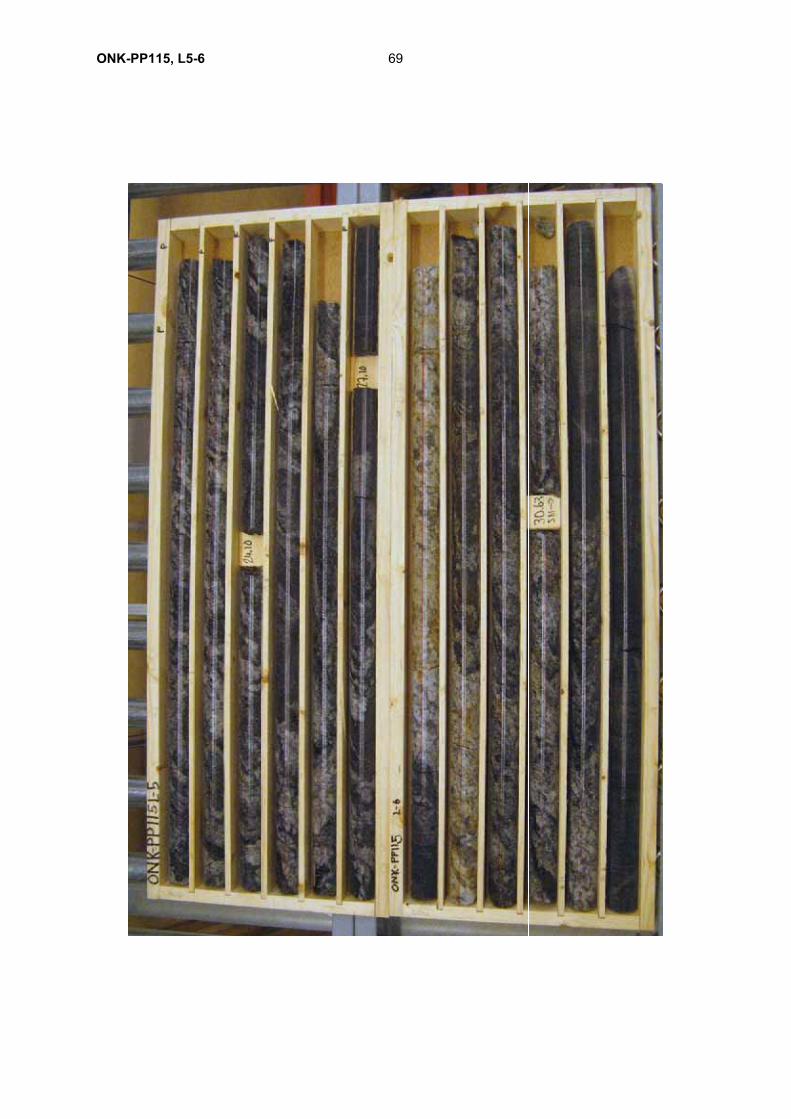
69ONK-PP115, L5-6
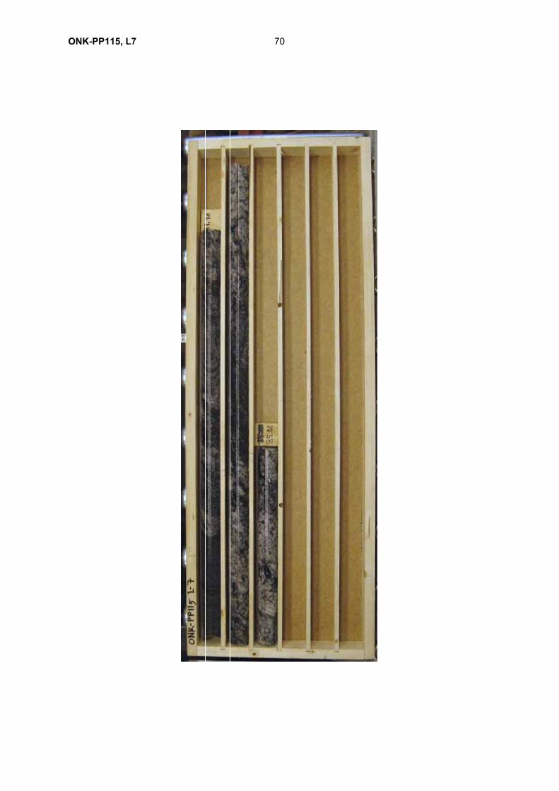
70ONK-PP115, L7
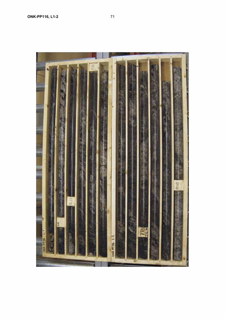
71ONK-PP116, L1-2
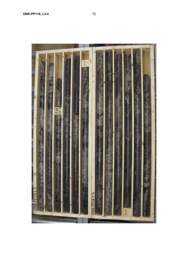
72ONK-PP116, L3-4
73ONK-PP116, L5-6
74ONK-PP116, L7
75ONK-PP117, L1-2
76ONK-PP117, L3-4
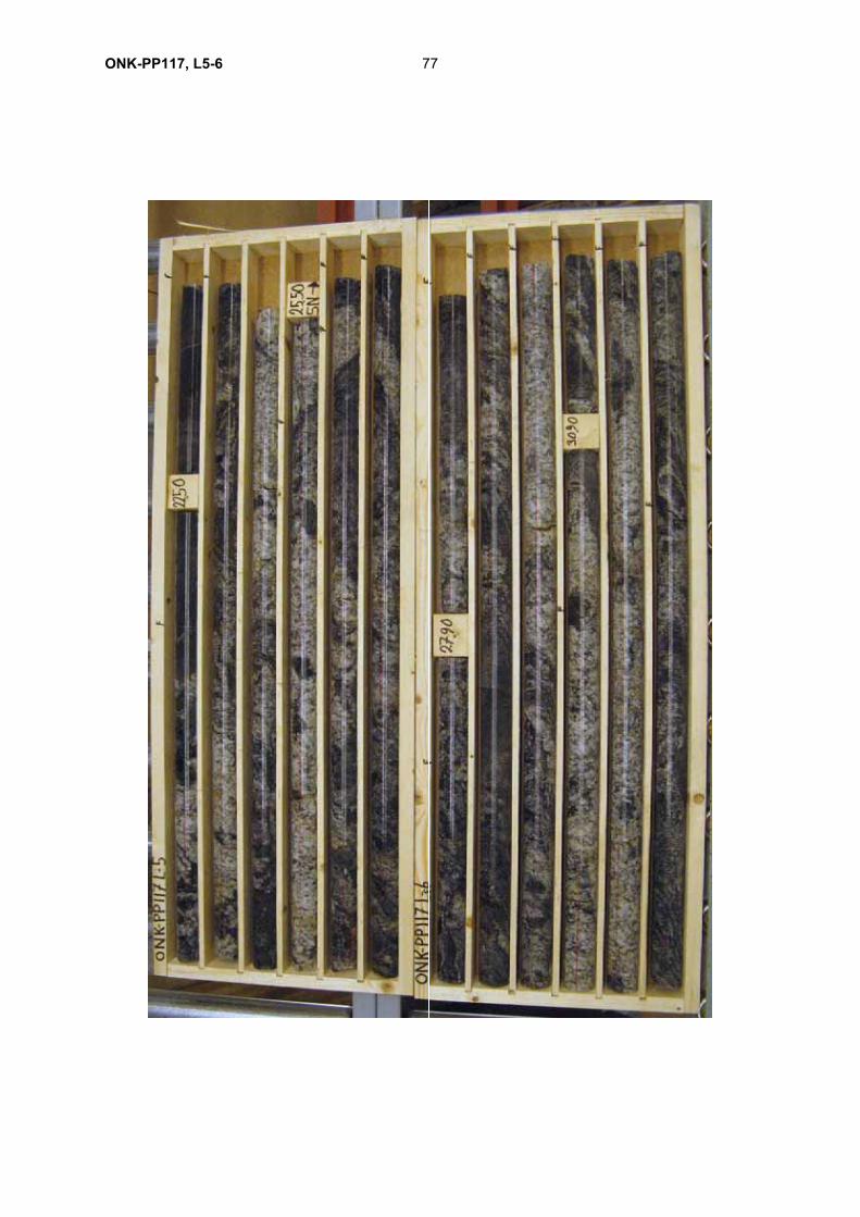
77ONK-PP117, L5-6
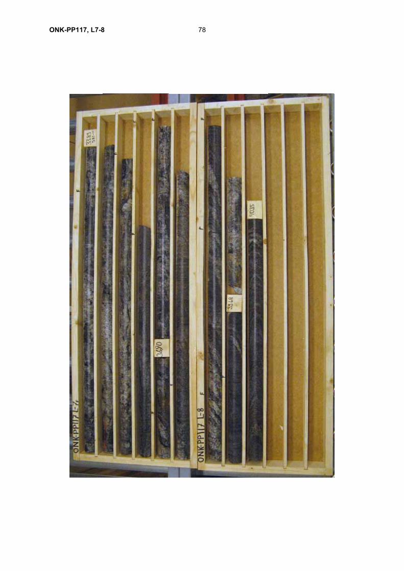
78ONK-PP117, L7-8
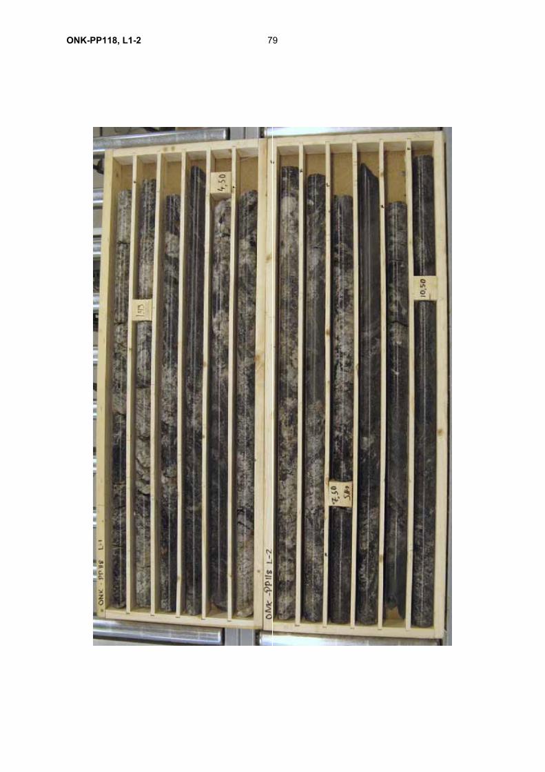
79ONK-PP118, L1-2
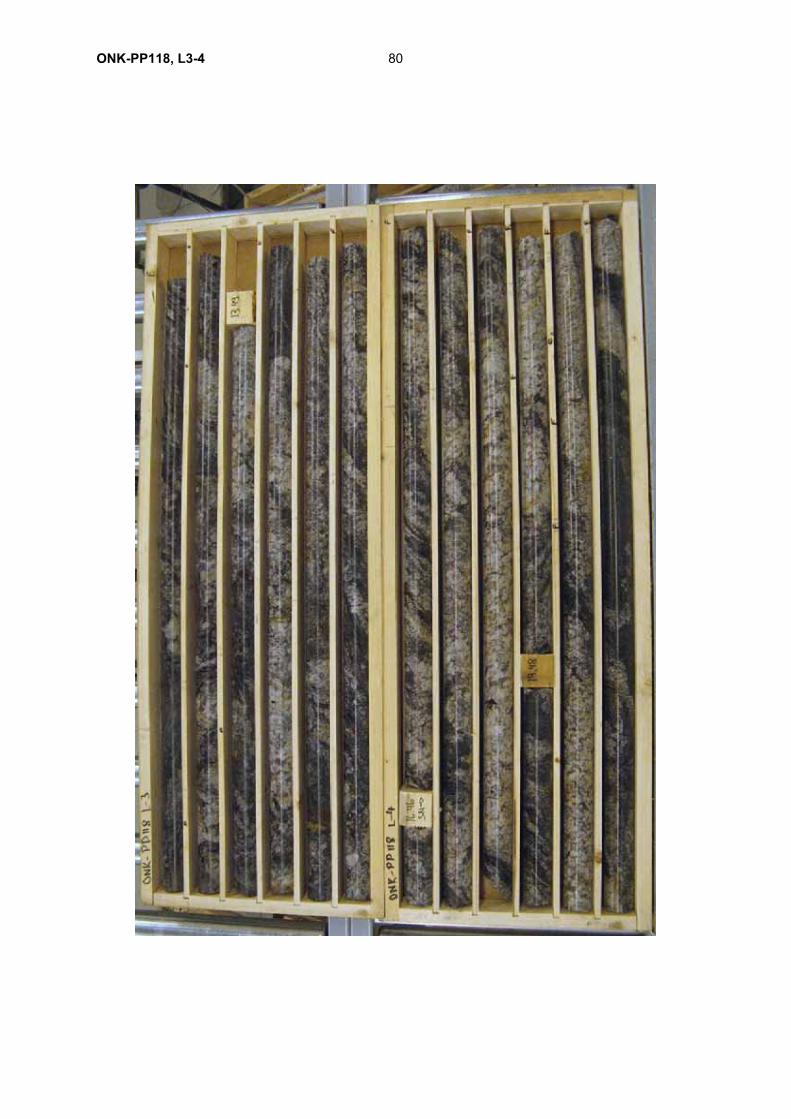
80ONK-PP118, L3-4
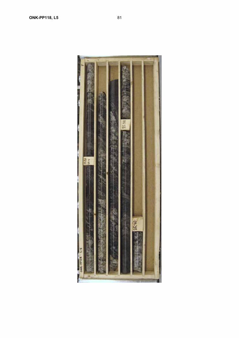
81ONK-PP118, L5
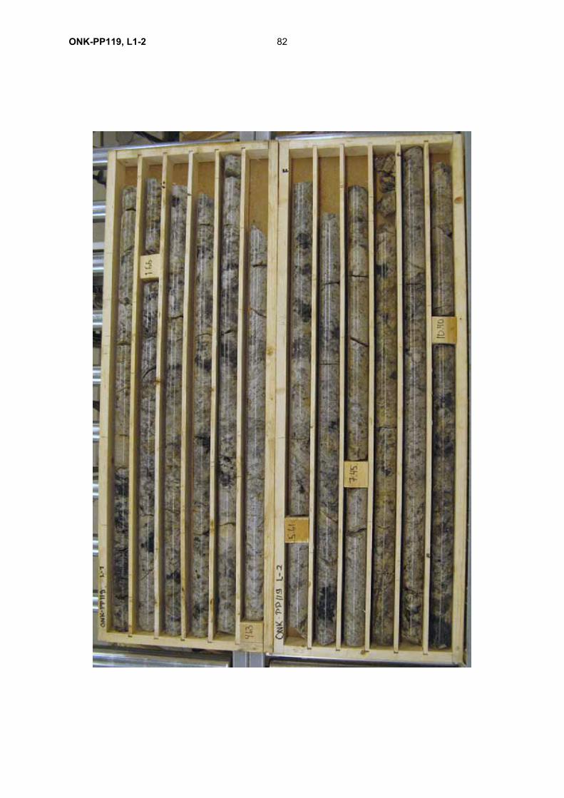
82ONK-PP119, L1-2
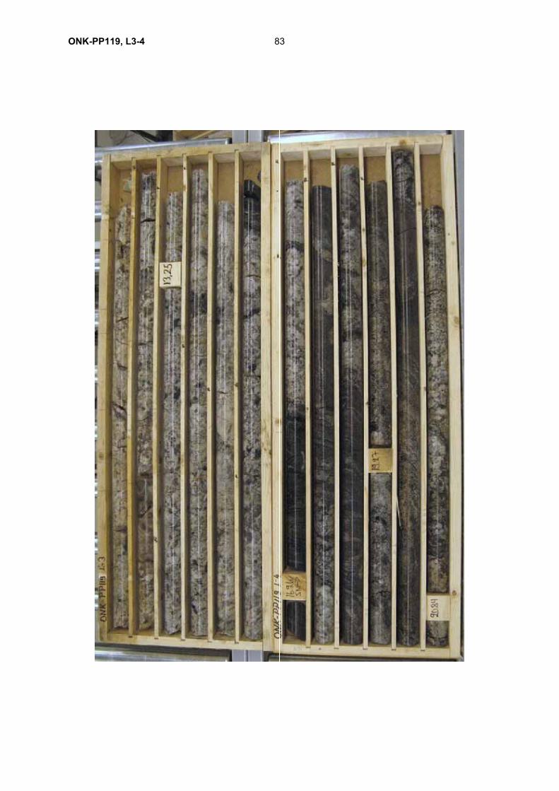
83ONK-PP119, L3-4
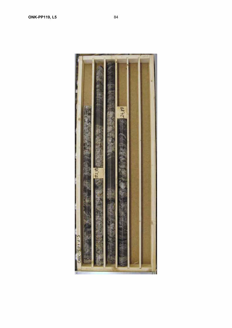
84ONK-PP119, L5
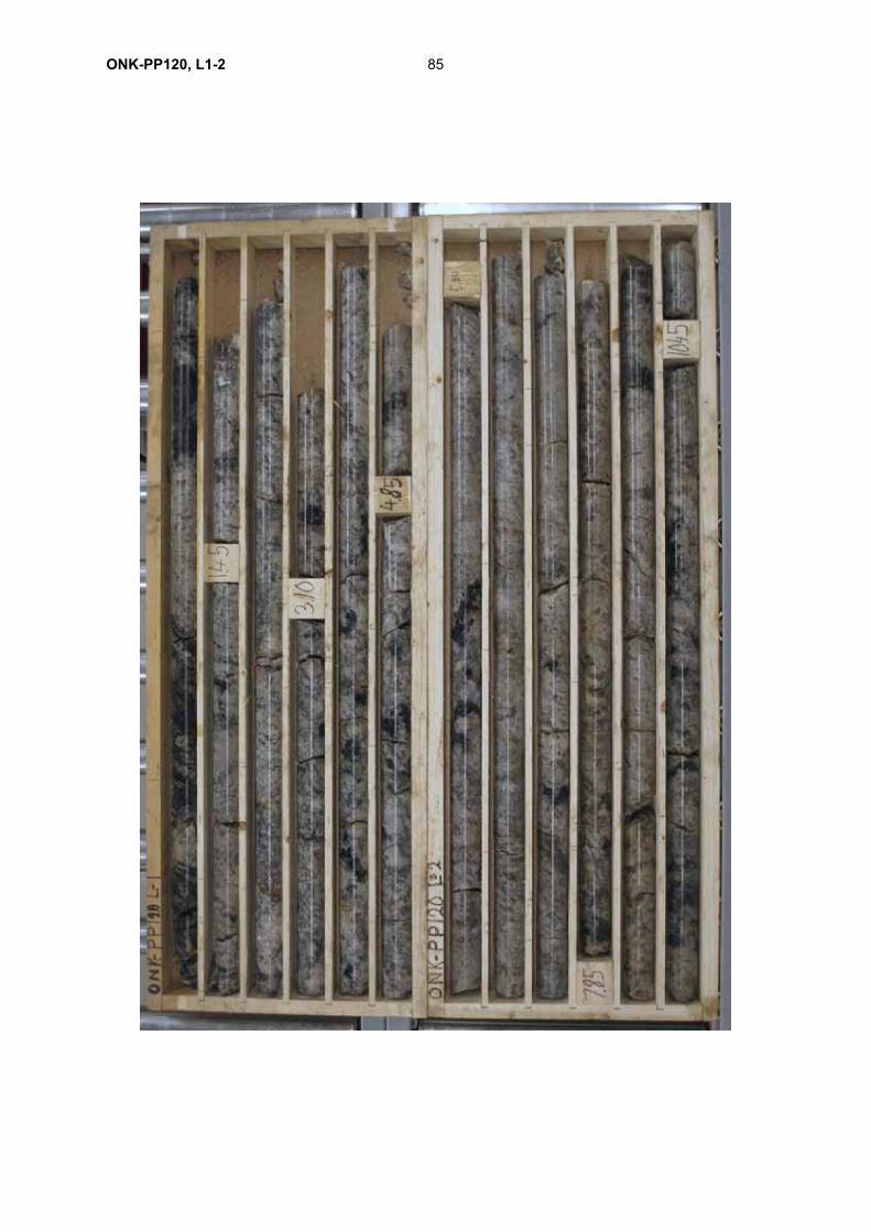
85ONK-PP120, L1-2
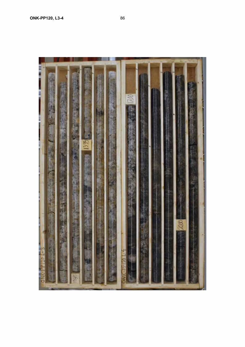
ONK-PP120, L3-4 86
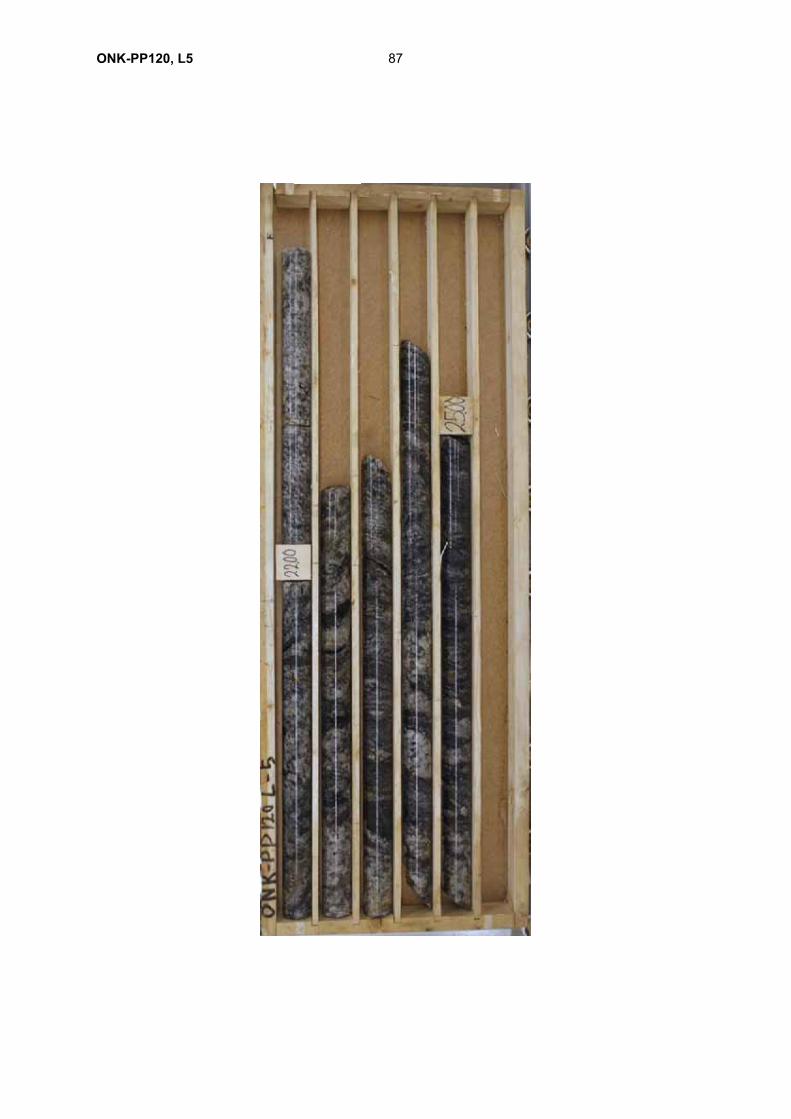
ONK-PP120, L5 87