Core Carbon Storage and Monitoring Research (CCSMR) … Library/Events/2016/fy16 cs rd/Thur... ·...
30
Core Carbon Storage and Monitoring Research (CCSMR) Field Testing of Emerging Technologies Task 4: CMC Containment and Monitoring Institute (CaMI) Project Number ESD14-095 Thomas M. (Tom) Daley Energy Geosciences Division Lawrence Berkeley National Laboratory U.S. Department of Energy National Energy Technology Laboratory Mastering the Subsurface Through Technology, Innovation and Collaboration: Carbon Storage and Oil and Natural Gas Technologies Review Meeting August 16-18, 2016
Transcript of Core Carbon Storage and Monitoring Research (CCSMR) … Library/Events/2016/fy16 cs rd/Thur... ·...

Core Carbon Storage and Monitoring Research
(CCSMR)
Field Testing of Emerging Technologies
Task 4:
CMC Containment and Monitoring
Institute (CaMI)Project Number ESD14-095
Thomas M. (Tom) Daley
Energy Geosciences Division
Lawrence Berkeley National LaboratoryU.S. Department of Energy
National Energy Technology Laboratory
Mastering the Subsurface Through Technology, Innovation and Collaboration:
Carbon Storage and Oil and Natural Gas Technologies Review Meeting
August 16-18, 2016

Coauthors/Collaborators
B.M. Freifeld*1, 1M. Wilt, 1P. Cook, D. Lawton3,
*LBNL Co-PI, 1 Lawrence Berkeley National Laboratory, 3CaMI, Univ of
Calgary,
Acknowledgement:
Mark Piercy - Schlumberger
Mark Woitt – RPS Engineering
3
Benefit to the Program
• Program goals being addressed:
– Develop and validate technologies to ensure
99 percent storage permanence.
– Develop technologies to improve reservoir storage
efficiency while ensuring containment effectiveness
• Project benefits:
– Deployment and testing of new monitoring
technologies and methodologies.
– Broader learnings from leveraged international
research opportunities
– Rapid transfer of knowledge to domestic programs

Monitoring Technology:
Supporting the SubTER ProgramWellbore Integrity
and Drilling
Technologies
Subsurface Stress
& Induced
Seismicity
Permeability
Manipulation &
Fluid Control
New Subsurface
Signals
Remediation tools and technologies
Fit-for-purpose drilling and completion tools
(e.g. anticipative drilling, centralizers,
monitoring)
HT/HP well constr. & completion
technologies
State of Stress (measurement and
manipulation)
Induced seismicity (measurement and
manipulation)
Relate Stress and IS to Permeability
Applied Risk Analysis to Assess Impact of
Subsurface Manipulation
Manipulating Physicochemical
Fluid-Rock Interactions
Manipulating Flow Paths to
Enhance/Restrict Fluid Flow
Characterizing Fracture Dynamics
and Fluid Flow
Novel Stimulation Technologies
New Sensing Approaches
Integration
of Multi-Scale, Multi-Type Data
Adaptive Control Processes
Diagnostic Signatures and Critical Thresholds
New diagnostics for wellbore integrity
Autonomous completions for well integrity modeling
Improved well
construction materials
and techniques
Energy Field Observatories
Fit For Purpose Simulation Capabilities
Relate Stress and IS to Permeability

5
Project Overview: Goals and Objectives
• The Core Carbon Storage and Monitoring Research
Program (CCSMR) aims to advance emergent
monitoring and field operations technologies that can be
used in commercial carbon storage projects. This effort
aligns with program goals:
– Improve estimates of storage capacity and sweep
efficiency
– Develop new monitoring tools and technologies to
achieve 99% storage confirmation
• Success criteria is if we are able to advance the
technology readiness level (TRL) of targeted
technologies from a level of TRL 3 – 5 up to 6 – 7
through leveraged field testing opportunities.

Advanced Monitoring Technology:
Seismic
• Issue: CO2 storage requires long term repeated monitoring– Active source seismic is an important monitoring tool, and we would
like to have data collected repeatedly for monitoring (i.e. semi-permanent), but…
– Marine seismic is expensive, with high fixed cost (few ‘small’ tests)
– Land seismic has unique difficulties (surface variability and access)
– Permanent seismic sensors are expensive for the large numbers (spatial sampling) needed
– Permanent seismic sources are not standard or generally available
• R&D Approach– DAS (distributed acoustic sensing) on fiber optic cables: a
promising technology to improve long term repeatable monitoring with permanent sensor installation and large spatial sampling
– Permanent, remote-controlled source: provide continuous monitoring and ‘trigger’ for full 3D seismic acquisition

Advanced Monitoring Technology:
CaMI Applications - EM
• Previous CO2 injection/storage pilots have focused on verifying storage integrity (“safe storage”)
• Monitoring and characterizing potential unwanted migration (‘leakage’) has different needs than monitoring storage
• Example: Intermediate depth, secondary accumulation of CO2in gas phase – detection limit, mass quantification
• Issue: – Quantification of CO2 is improved with muti-physics
measurements (e.g. Electromagnetic (EM) and Seismic)
• Opportunity:– Advance electrical/EM monitoring - access to fiberglass well and
installed electrodes (borehole and surface)
• R&D approach: – Apply electrical and seismic monitoring methods and use joint-
inversion to improve CO2 saturation estimates
– Initial Focus: High resolution EM and Seismic Crosswell Tomography 7
Technical Status
8
• Initial development of high frequency EM
crosswell and surface-borehole
instrumentation completed
• Full scale test expected to begin next
week at LBNL
• Baseline surveys at CaMI planned for Oct
2016

9
From Lawton, 2016

10
From Lawton, 2016

11
From Lawton, 2016

12
From Lawton, 2016

13

LBNL/DOE at CaMI
• Applying Higher TRL Tools to Novel Experiment
– Borehole instrument deployment • fiber optic cables
• Integrated DTS – Heat Pulse cable
• U-tube fluid sampling
• Pressure-Temperature Gauge
– Cross-well seismic surveys (LBNL)
• Advancing Lower TRL Tools
– Cross-well electromagnetic surveys
– Surface-borehole electrical/EM surveys*
– Surface-borehole electrical resistivity surveys
– Surface helical fiber cable for DAS surface seismic
– Borehole helical cable for crosswell DAS 14
*New technology focused on CaMI, utilizing available fiberglass casing

Crosswell Seismic
Planned Survey Parameters:
• Sensor: Hydrophone array –20 sensors at 5 m spacing
• Source: piezoelectric
• Source sweep: 300-2500 Hz
• Spatial sampling: 0.5 m
• Issue: seismic alone has uncertainty in CO2 saturation
• Should reduce uncertainty with conductivity (EM crosslwell)
15
Example from Cranfield, Ajo-
Franklin, et al, 2012

High Frequency Crosswell
EM• Moving prototype system to field operation
ready
• Frequencies from 10 Hz to 20 kHz
• well spacing's from 20m to over 500m, and depths to 2km.
• Only one Fiberglass well available for CaMI Phase 1, so frequency is reduced (~200 Hz)
• Multi-level Sensor tool
• Obtain 2D resistivity map at depth
16
20 m
Example High
Frequency EM
Tomography
(Wilt, et al, 1995)ReceiverTransmitter
Waveform generator
Power amp
Current monitor Isolated cable Voltmeter
ref
ref
Rcv1
Rcv2
Rcv1
Rcv2Tx
Logging interval
Depth encoder cable
Logging computer

Crosswell EM Tools
17
Sensors (1 -5 levels)• Size 2-level (5 m spacing)
– Diameter 2.5” ( 7 cm)
– Length ~6 ft (2 m)
– Weight ~ 30 lbs (12 kg)
• Coil Make up– 1” mu-metal core 1m long 8
– 20,000 turns of wire on core
– Tuning capacitors on internal circuit
• Frequency– 1- 10000 Hz; Flat 10-1000Hz
• Sensitivity – 0.1 V/nTesla
– Noise estimated at 10-6 nT
Transmitter Source
• Size– Diameter 3.5” ( 8 cm)
– Length ~12 ft (4 m)
– Weight ~ 120 lbs (50 kg)
• Coil Make up– 2.5” Ferrite core 8 ft long
– 1000 turns of wire on core
– Tuning capacitors on internal circuit
• Frequency– 1- 4000 Hz
• 1-500 Hz untuned,
• Tuning 1, 1.5 2 and 4 khz. Selectable by software
• Dipole Moment– Maximum moment 1500 A-m2
High Frequency (<4 kHz) Source
Multi-level Sensor Coils

EM Surface to Borehole
18
• Crosswell EM limited when second monitoring well changed from fiberglass to steel casing: decided to add surface-borehole EM
• Preliminary numerical modeling (borehole-to-surface) indicated:– surface to borehole EM will provide good sensitivity to a CO2 target of
modest size at CAMI assuming CO2 saturation of 20-30%.
– optimal frequency of operation should be in the range of 500-2000Hz
• Preliminary measurement plans calls for a distribution of tangential transmitters of 500 Hz with borehole receivers covering a depth interval of 150-350m, with data recovery up to 2.5 kHz.
-200 -100 0 100 200
10-12
10-11
X axis(m)
Ey(V
/m)
Before injection
1 month
4 month
7 month
9 month
12 month
Borehole to Surface EM
Model (Evan Um, Mike Wilt)
Electric field amplitude (V/m)
Conclusion:
• Time-lapse changes due to
CO2 injection observable
• Maximum change at
intermediate time

LBNL Geochemical Fluid Sampling:
U-Tube Behind Casing
19
From Lawton, 2016
Paul Cook and Barry Freifeld
LBNLU-Tube Fluid Sampler
On Casing

Borehole Sensor Deployment
20
Fiber from HWC
(Helical Wound
Cable) OBS Well #2
Cables for
Geophones and
ElectrodesPhotos: Paul Cook
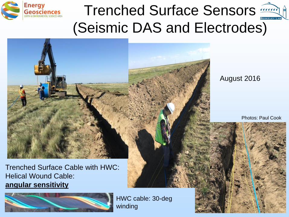
Trenched Surface Sensors
(Seismic DAS and Electrodes)
21
August 2016
Trenched Surface Cable with HWC:
Helical Wound Cable:
angular sensitivity
HWC cable: 30-deg
winding
Photos: Paul Cook

Surface Orbital Vibrator
Controlled AC Motor w/Eccentric Mass
Max Frequency 80 Hz, Force (@80Hz) 10 T-fPhase stability is not maintained. Operate 2.5 hr/d
Force is adjustable
F=mω2r

Accomplishments to Date
• Collaboration with CaMI on monitoring program
• Preliminary EM Modeling
• Development of crosswell EM instrumentation
(raise TRL level)
• Deployment of helical (and straight fiber) cable
in observation wells – first time for helical in well!
• Deployment of U-Tube geochemical sampling
system in observation wells
• Planning/design of crosswell EM and Seismic
surveys23

Synergy Opportunities
– Deployment of fiber optic cables in the subsurface allows multiple measurements (Temperature, Acoustics, Chemistry)
– Permanent sensor deployments with semi-permanent sources allows ‘continuous’ monitoring
24
ADM Intelligent Monitoring System
Thursday, 4:35 PM : B. FreifeldDeep Controlled Source Electro-Magnetic Sensing: A
Cost Effective, Long-Term Tool for Sequestration
Monitoring - Multi Phase Technologies LLC - Douglas
LaBrecque
Distributed Fiber Optic Arrays: Integrated
Temperature and Seismic Sensing for Detection of
CO2 Flow, Leakage and Subsurface Distribution -
Electric Power Research Institute Inc. - Robert Trautz

Summary
– Key Findings• CaMI fills an important need in storage R&D: intermediate
depth, gas phase detection/monitoirng
• LBNL/DOE is adding to a comprehensive monitoring program by applying high TRL tools and advancing lower TRL tools
• Crosswell EM and seismic; U-Tube sampling; heat pulse monitoring; surface and borehole helical DAS;
– Lessons Learned• Plans need to be flexible while project is developing (e.g.
change from 2 fiberglass casing to 1 +1 steel
– Future Plans• Acquire baseline data ~ Oct 2016
• Begin injection
• Monitor co2 plume25

Acknowledgements
• Funding for LBNL was provided through the Carbon Storage Program, U.S. DOE, Assistant Secretary for Fossil Energy, Office of Clean Coal and Carbon Management, through the NETL, for the project “Core Carbon Storage and Monitoring Research” (CCSMR).
• Carbon Management Canada (CMC) Containment and Monitoring Institute (CaMI) Field Research Station (FRS)

Appendix
– These slides will not be discussed during the
presentation, but are mandatory
27

28
Organization Chart
• CMC CaMI Project Management: Don Lawton
• CMC CaMI monitoring lead: Don Lawton
• LBNL – co-PIs: Tom Daley and Barry Freifeld
– Field Support, Installation and Instrumentation: Paul Cook
– EM R&D: Mike Wilt
• Carbon Management Canada (CMC) organized the Containment and Monitoring Institure (CaMI) which is led by Don Lawton. Mark Piercy of Schlumberger provides in-field logistical support and management at the CaMI Field Research Station (FRS).

29
Gantt Chart
TASK 4. Carbon Management Canada FRS Collaboration
Milestone 4-1 (E)Title: Integrated behind casing monitoring well design and installation planPlanned Completion (Reporting) date: Q2 3/31/16 (4/30/2016)Verification Method: Quarterly Progress report
Milestones 4-2 (F)Title: Description of design and laboratory testing of borehole electro-magnetic (EM) source and multi-level borehole EM senor array for CO2 monitoring. Planned Completion (Reporting) date: Q3 6/30/16 (7/31/2016) Note: delayed due to funding gapVerification Method: Quarterly Progress report and supplement

Bibliography
• No Journal Publications, specific to CaMI, as of now
30