Cordless Drill & Driver Model No. EY74A2 - Homberger S.p.A. · 6 3.2. Trial Operation (after...
16
© Panasonic Corporation 2015. All rights reserved. Unauthorized copying and distribution is a violation of law. ORDER NO. PTD1507X58CE Cordless Drill & Driver Model No. EY74A2 Europe Oceania TABLE OF CONTENTS PAGE PAGE 1 Warning -------------------------------------------------------------- 2 2 Specifications ----------------------------------------------------- 2 3 Troubleshooting Guide ----------------------------------------- 3 4 Disassembly and Assembly Instructions ---------------- 7 5 Wiring Connection Diagram ---------------------------------13 6 Schematic Diagram ---------------------------------------------13 7 Exploded View and Replacement Parts List -----------14
Transcript of Cordless Drill & Driver Model No. EY74A2 - Homberger S.p.A. · 6 3.2. Trial Operation (after...

© Panasonic Corporation 2015. All rights reserved.
Unauthorized copying and distribution is a violation
of law.
ORDER NO. PTD1507X58CE
Cordless Drill & Driver
Model No. EY74A2Europe
Oceania
TABLE OF CONTENTSPAGE PAGE
1 Warning -------------------------------------------------------------- 2
2 Specifications ----------------------------------------------------- 2
3 Troubleshooting Guide ----------------------------------------- 3
4 Disassembly and Assembly Instructions ---------------- 7
5 Wiring Connection Diagram ---------------------------------13
6 Schematic Diagram ---------------------------------------------13
7 Exploded View and Replacement Parts List -----------14

2
1 WarningCaution:
• Pb free solder has a higher melting point that standard solder; Typically the melting point is 50 - 70 °F (30 - 40 °C) higher.
Please use a soldering iron with temperature control and adjust it to 750 ± 20 °F (400 ± 10 °C). In case of using high temperature
soldering iron, please be careful not to heat too long.
• Pb free solder will tend to splash when heated too high (about 1100°F / 600 °C).
2 Specifications
3
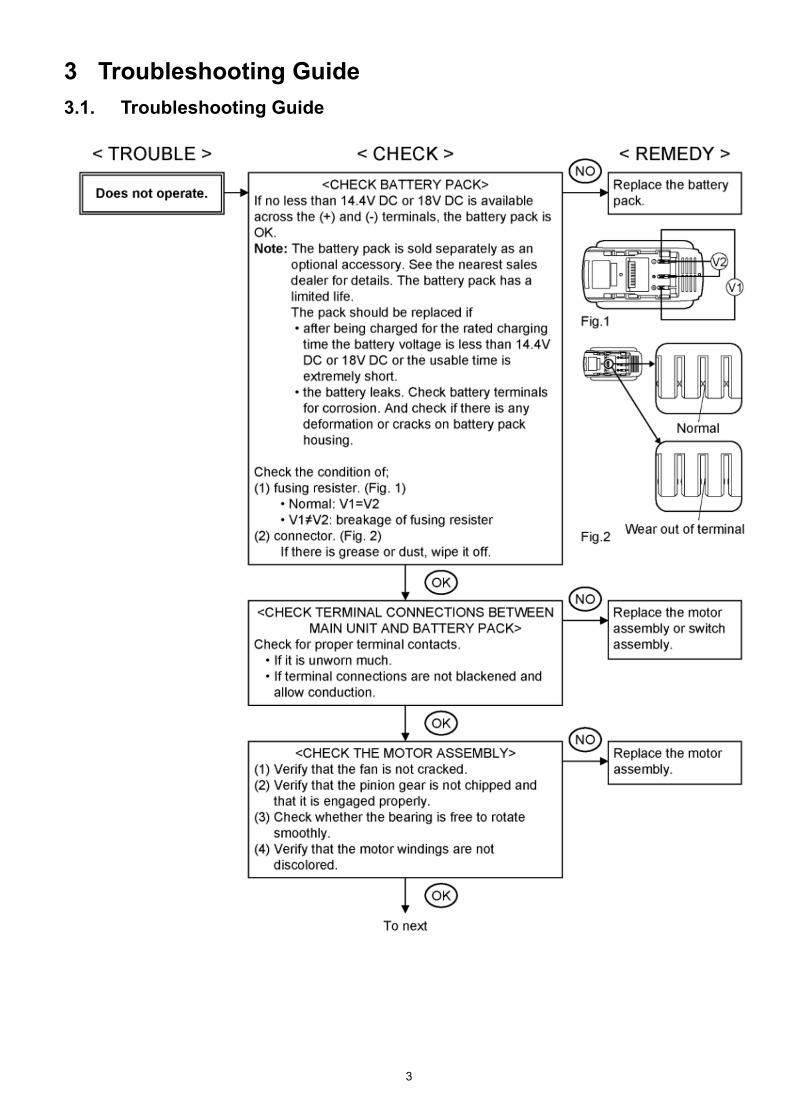
3 Troubleshooting Guide
3.1. Troubleshooting Guide

4

5

6
3.2. Trial Operation (after checking Troubleshooting Guide).
3.2.1. Assembly• Confirm if there is no gap between housing A, B and C by pinching lead wires.
• There is no dust or deformation on battery terminals.
3.2.2. Operation• Check whether the tool operates properly in both the forward and reveres directions.
• Press the light button on the operation panel to confirm that the LED lights up.
• Check whether the tool speed increases continuously as the trigger is gradually engaged.
• Rotate the clutch handle and check whether the clutch switches properly.
• Check if the rotation speed is normal rated value.
High: 1580/min (rpm) at 18V, 1350/min (rpm) at 14.4V
Low: 470/min (rpm) at 18V, 400/min (rpm) at 14.4V
• Pull the trigger all the way back and check whether the tool stops rotating immediately when it is released.
• Set the clutch handle to the [ ] mark and check whether the tool rotates without any clutch operation.
• Operate (rotate) the keyless chuck and check whether the chuck's three jaws move smoothly.
3.2.3. Integrity• With the switch activated, shake the tool back and forth and up and down and verify that its sound does not change excessively.
• Check for the presence of any dirt or foreign matter from the repair process on the outside of the tool.
7
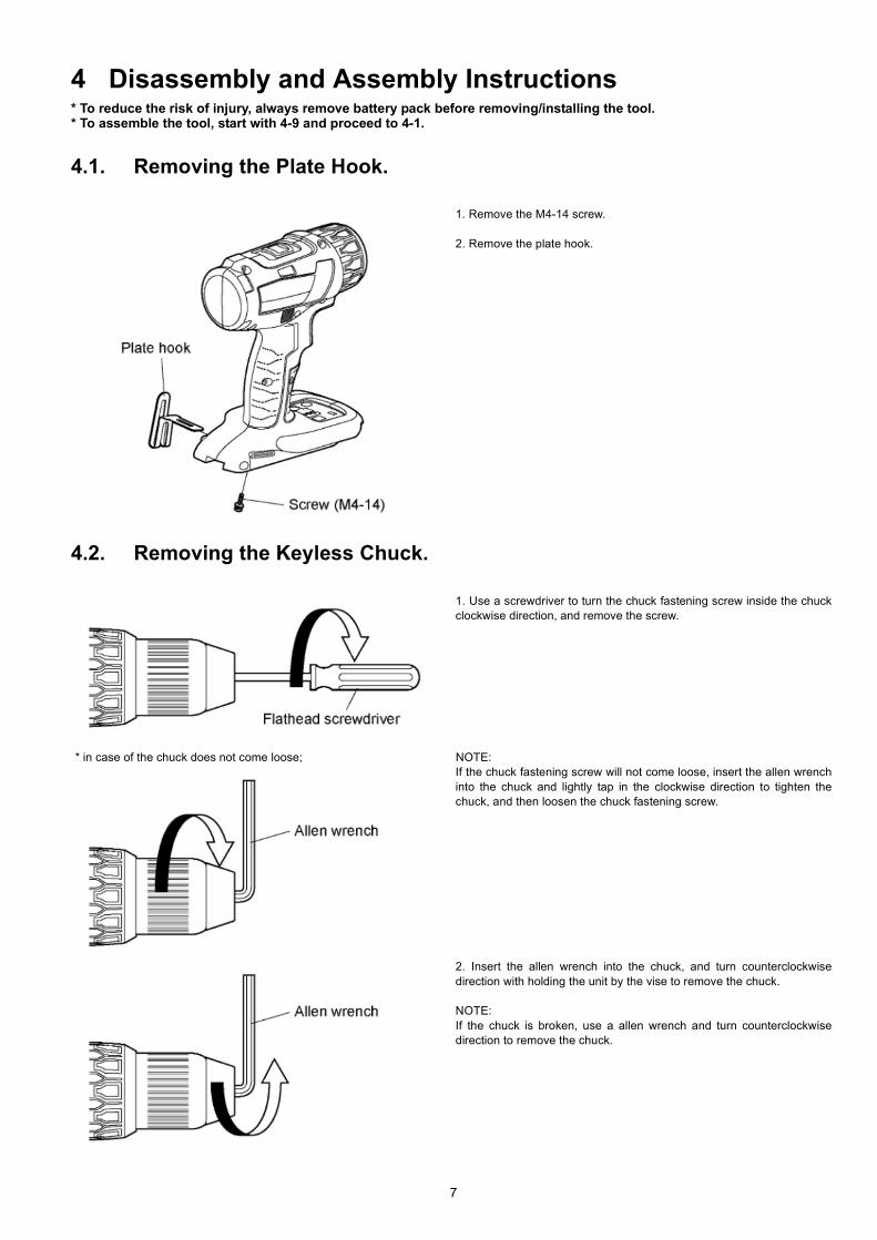
4 Disassembly and Assembly Instructions* To reduce the risk of injury, always remove battery pack before removing/installing the tool.* To assemble the tool, start with 4-9 and proceed to 4-1.
4.1. Removing the Plate Hook.
4.2. Removing the Keyless Chuck.
1. Remove the M4-14 screw.
2. Remove the plate hook.
1. Use a screwdriver to turn the chuck fastening screw inside the chuck
clockwise direction, and remove the screw.
* in case of the chuck does not come loose; NOTE:
If the chuck fastening screw will not come loose, insert the allen wrench
into the chuck and lightly tap in the clockwise direction to tighten the
chuck, and then loosen the chuck fastening screw.
2. Insert the allen wrench into the chuck, and turn counterclockwise
direction with holding the unit by the vise to remove the chuck.
NOTE:
If the chuck is broken, use a allen wrench and turn counterclockwise
direction to remove the chuck.

8
4.3. Removing the Housing.
4.4. Removing the Interior Components.
1. Remove nine screws.
2. Remove housing B.
3. Remove the F/R selector handle.
4. Remove the operation panel.
5. Remove the square nut.
1. Remove the heat resistant tape and remove the interior components
from the housing A.
* Precautions when securing LED assembly in place using the resistant
tape.
Attach the heat resistant tape at the location shown in the figure below.
2. Remove the clutch handle, H/L change handle and click spring from
the gear block assembly.

9
4.5. Removing the Switch Assembly, LED Assembly and Battery Terminal.
4.6. Removing the Gear Case Assembly from the Module Assembly.
1. Remove the 2-pin connector.
2. Remove the 6-pin connector.
3. Pull the faston terminal directly
out from the switch assembly.
* Exercise care not to bend the ter-
minal fitting.
4. Remove the lead wires from the
battery terminal.
Connecting and disconnecting the connector
* Precautions when attaching the connectors
Holding the motor assembly, remove the entire motor mounting plate,
including the gear box assembly from the motor assembly.

10
4.7. Removing the Gear Case Assembly.
1. Rotate the motor mounting plate to the
left and remove it from the gear case.
2. Remove the thrust plate, planet gear
B, ring gear B, carrier B, planet gear A,
carrier A, and the ring gear A (in that
order).
3. Remove 4 screws.
4. Remove the gear case, stopper, thrust
plate, planet gear, ring gear, carrier, steel
balls, pin, cushion plate, lock plate, lock
ring, thrust plate, wave washer and
thrust plate (in that order).
5. Insert the jaws of snap ring into two
holes on the C-ring. Open the jaws and
lift up on the ring to remove it.
* The C-ring cannot be reused after
being repaired or otherwise adjusted.
6. Remove the driving shaft, thrust plate,
steel balls, thrust plate, adjust screw,
clutch spring and thrust plate from the
clutch case.
* Assembly precautions1. Exercise care when attaching the lock ring, ring gear, stopper, and ring
gear A to align them in the proper orientation (as shown in the above figure).
2. When installing the gear case to the clutch case, be sure to align the pro-
truding ribs on the clutch case with the recessed ribs on the gear case.
3. When installing the motor mounting plate to the gear case, align and
engage the two protruded sections on motor mounting plate with the two
notches on the gear case, then turn the motor mounting plate clockwise until
a clicking sound is produced to ensure secure mounting.
4. When installing the adjusting screw, make sure that the narrow protrusion
is on the right and flush with the clutch case surface.
5. Precautions when applying the grease (ALVANIA).

11
4.8. Assembly of the Gear Case Assembly and the Clutch Handle.
4.9. Assembly of the H/L Change Handle.
Align the gear case assembly's adjusting screw as shown in the figure.
Position so that the [1] mark on the clutch handle is Aligned with the center of click spring A.
12
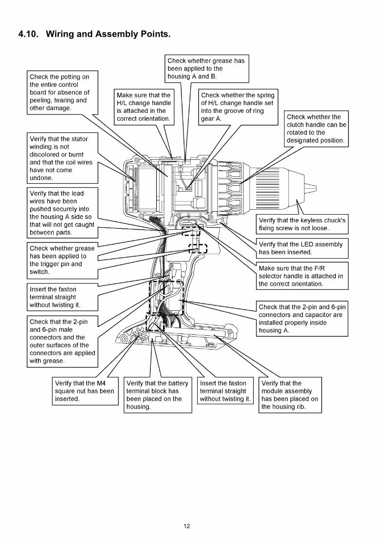
4.10. Wiring and Assembly Points.

13
5 Wiring Connection Diagram
6 Schematic Diagram

Model No. : EY74A2 Exploded View

Model No. : EY74A2 Parts List
Change SafetyRef. No.
Part No. Part Name & Description Q'ty Remarks
1 WEY6450L6806 CHUCK FASTENING SCREW 1
2 WEY74A2K7917 CHUCK 1
3 WEY7441K9038 TAPPING SCREW 8 (K3-20)
4 WEY74A2K3079 HOUSING AB SET 1 (For EUROPE)
4 WEY74A2K3070 HOUSING AB SET 1 (For OCEANIA)
5 WEY75A7H3247 F/R SELECTOR HANDLE 1
6 WEY74A2K3958 OPERATION PANEL 1
7 WEY7443W0957 HEAT RESISTANT TAPE 1
8 WEY74A2H3237 H/L CHANGE HANDLE 1
9 WEY74A2K3227 CLUTCH HANDLE 1
10 WEY74A1L0178 CLICK SPRING A 1
11 WEY75A7K2008 SWITCH ASSEMBLY 1
12 WEY75A7K2157 BATTERY TERMINAL ASSEMBLY 1
13 WEY74A2H4147 GEAR BLOCK ASSEMBLY 1
14 WEY74A2S1157 DRIVING SHAFT 1
15 WEY74A2L1917 STEEL BALL 15 (2.5 DIA)
16 WEY74A2L0847 THRUST PLATE 2 (14.9 DIA)
17 WEY74A2F0637 ADJUST SCREW 1
18 WEY74A2S0167 CLUTCH SPRING 1
19 WEY74A2L0577 THRUST PLATE 1
20 WEY74A2F3297 CLUTCH CASE ASSEMBLY 1
21 WEY74A2L6768 C-RING 1
22 WEY74A2L0857 THRUST PLATE 1
23 WEY74A2S6097 WAVE WASHER 1
24 WEY74A2L0867 THRUST PLATE 1
25 WEY74A2S0647 LOCK RING 1
26 WEY74A2S0207 LOCK PLATE 1
27 WEY74A2S0317 CUSHION PLATE 1
28 WEY74A2S0507 PIN 6
29 WEY74A2S1927 STEEL BALL 12 (5 DIA)
30 WEY74A2L1647 CARRIER 1
31 WEY74A2L1477 RING GEAR 1
32 WEY74A2S1357 PLANET GEAR 6
33 WEY74A2K0847 THRUST PLATE 1
34 WEY74A2S0397 STOPPER 1
35 WEY74A2F1767 GEAR CASE 1
36 WEY74A2K9037 TAPPING SCREW 4 (3*12)
37 WEY74A2L1417 CARRIER A 1
38 WEY74A2L1467 RING GEAR A 1
39 WEY74A2L1368 PLANET GEAR A 3
40 WEY74A2L1457 CARRIER B 1
41 WEY74A2L1487 RING GEAR B 1
42 WEY74A2L1397 PLANET GEAR B 3
43 WEY74A2K0857 THRUST PLATE 1
44 WEY74A2F0027 MOTOR MOUNTING PLATE 1
45 WEY75A7L2337 LED ASSEMBLY 1
46 WEY74A2L1008 MOTOR ASSEMBLY 1
47 WEY7441L6487 NUT 1 (M4)
48 WEY7543K3187 PLATE HOOK 1
49 WEY7441K6217 SCREW 1 (4*14)
50 WEY9L40R2788 BATTERY PACK COVER 1
- WEY74A1K7018 TOOL CASE 1
- WEY74A2K8109 OPERATING INSTRUCTIONS 1
- WEY7543X5517 GREASE (SUMITEC) 1
- WEY001T8907 GREASE (ALVANIA) 1