Copyright R. Janow - Fall 2015 1 Electricity and Magnetism Lecture 07 - Physics 121 Current,...
28
1 Copyright R. Janow - Fall 2015 Electricity and Magnetism Lecture 07 - Physics 121 Current, Resistance, DC Circuits: Y&F Chapter 25 Sect. 1-5 Kirchhoff’s Laws: Y&F Chapter 26 Sect. 1 • Currents and Charge • Electric Current i • Current Density J • Drift Speed, Charge Carrier Collisions • Resistance, Resistivity, Conductivity • Ohm’s Law • Power in Electric Circuits • Examples • Circuit Element Definitions • Kirchhoff’s Rules • EMF’s - “Pumping” Charges, Ideal and real EMFs • Work, Energy, and EMF • Simple Single Loop and Multi-Loop Circuits using Kirchhoff Rules • Equivalent Series and Parallel Resistance formulas using Kirchhoff Rules.
-
Upload
charla-conley -
Category
Documents
-
view
214 -
download
0
Transcript of Copyright R. Janow - Fall 2015 1 Electricity and Magnetism Lecture 07 - Physics 121 Current,...

1Copyright R. Janow - Fall 2015
Electricity and MagnetismLecture 07 - Physics 121 Current, Resistance, DC Circuits: Y&F Chapter 25 Sect. 1-5Kirchhoff’s Laws: Y&F Chapter 26 Sect. 1
• Currents and Charge• Electric Current i• Current Density J• Drift Speed, Charge Carrier Collisions• Resistance, Resistivity, Conductivity• Ohm’s Law• Power in Electric Circuits• Examples• Circuit Element Definitions• Kirchhoff’s Rules• EMF’s - “Pumping” Charges, Ideal and real EMFs• Work, Energy, and EMF• Simple Single Loop and Multi-Loop Circuits using
Kirchhoff Rules• Equivalent Series and Parallel Resistance formulas
using Kirchhoff Rules.
Copyright R. Janow - Fall 2015
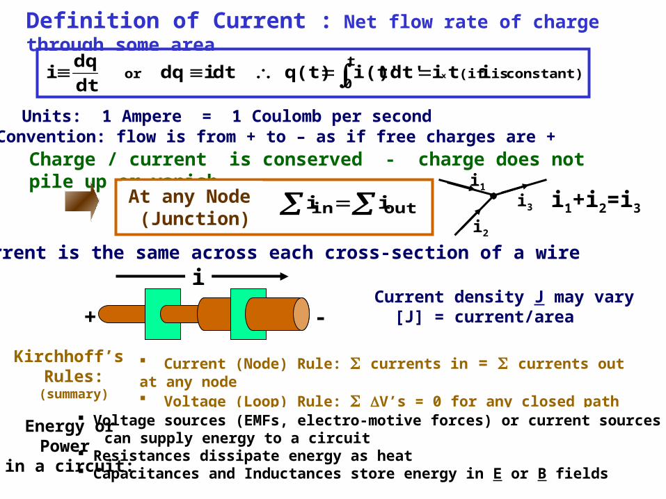
Definition of Current : Net flow rate of charge through some area
Current is the same across each cross-section of a wire
+ -
iCurrent density J may vary [J] = current/area
constant) is (ift
0or it i )dt'i(t'q(t) dt idq
dt
dqi x
Convention: flow is from + to – as if free charges are +Units: 1 Ampere = 1 Coulomb per second
Charge / current is conserved - charge does not pile up or vanish
At any Node (Junction)
outin i ii1
i2
i3 i1+i2=i3
Kirchhoff’s Rules:
(summary)
Current (Node) Rule: currents in = currents out at any node Voltage (Loop) Rule: V’s = 0 for any closed path Voltage sources (EMFs, electro-motive forces) or current sources can supply energy to a circuit Resistances dissipate energy as heat Capacitances and Inductances store energy in E or B fields
Energy orPower
in a circuit:

Copyright R. Janow - Fall 2015
Junction Rule Example – Current Conservation
7-1: What is the value of the current marked i?
A. 1 A.B. 2 A.C. 5 A.D. 7 A.E. Cannot determine from information given.
5 A
2 A 2 A
3 A1 A
6 A
i
outin i i
3 A
8 A
1 A
= 7 A

Copyright R. Janow - Fall 2015
Current density J: Current / Unit Area (Vector)
What makes current flow?Microscopic level /1 E J EJ
conductivity
Same current crosses larger or smallerSurfaces, current density J varies+ -
iA
A’
J’ = i / A’(small)
J = i / A(large)
High current densityin this region
Small current densityin this regioni
AdJi area
dAn̂Jdi
units: Amperes/m2 For uniform density: i/A J A J i or
For non-uniform density:
Drift speed: Do electrons in a current keep accelerating?
Yes, for isolated charge in vacuum. No, in a conducting solid, liquid, gas
resistivity
Copyright R. Janow - Fall 2015
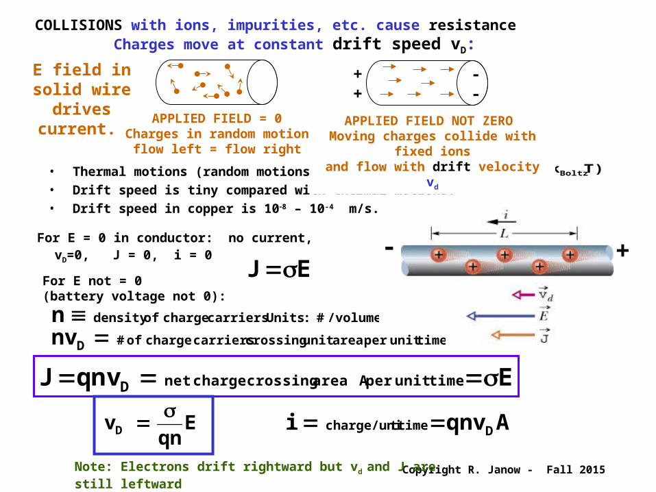
COLLISIONS with ions, impurities, etc. cause resistance Charges move at constant drift speed vD:
• Thermal motions (random motions) have speed • Drift speed is tiny compared with thermal motions.• Drift speed in copper is 108 – 10-4 m/s.
)Tk( m/s10v Boltz2
36th
E field in solid wire
drives current.
APPLIED FIELD = 0Charges in random motion
flow left = flow right
++
--
APPLIED FIELD NOT ZERO Moving charges collide with fixed
ionsand flow with drift velocity vd
+-
Note: Electrons drift rightward but vd and J are still leftward |q| = e = 1.6 x 10⁻¹⁹ C.
For E = 0 in conductor: no current, vD=0, J = 0, i = 0
For E not = 0 (battery voltage not 0):
E J
/volume# :Units carriers charge of density n time unit per area unit crossing carriers charge of# D nv
E vqn J time unit per A area crossing charge netD
A qnv i Dtime tcharge/uni Eqn
v D
Copyright R. Janow - Fall 2015
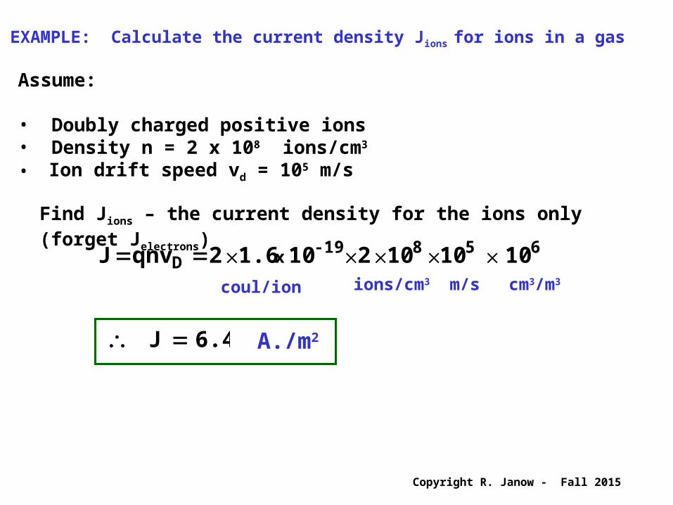
EXAMPLE: Calculate the current density Jions for ions in a gas
Assume:
• Doubly charged positive ions• Density n = 2 x 10⁸ ions/cm3
• Ion drift speed vd = 105 m/s
Find Jions – the current density for the ions only (forget Jelectrons) 6
58-19
xD 10 1010 2 10 1.6 2 qnv J coul/ion ions/cm3 m/s cm3/m3
6.4 J A./m2

Copyright R. Janow - Fall 2015
Increasing the Current
7-2: When you increase the current in a wire, what changes and what is constant?
A. The density of charge carriers stays the same, and the drift speed increases.
B. The drift speed stays the same, and the number of charge carriers increases.
C. The charge carried by each charge carrier increases.D. The current density decreases.E. None of the above
E J EJ
Dqnv J
Copyright R. Janow - Fall 2015
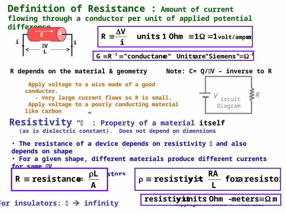
Definition of Resistance : Amount of current flowing through a conductor per unit of applied potential difference.
evolt/amper 1 1Ohm 1 :units i
VR
R depends on the material & geometry Note: C= Q/V – inverse to R
i iV
E
L
A
Apply voltage to a wire made of a good conductor. - Very large current flows so R is small. Apply voltage to a poorly conducting material like carbon - Tiny current flows so R is very large.
RCircuit
Diagram
V
Resistivity “” : Property of a material itself (as is dielectric constant). Does not depend on dimensions
• The resistance of a device depends on resistivity and also depends on shape• For a given shape, different materials produce different currents for same V• Assume cylindrical resistors
resistor a for L
RA yresistivit
A
L resistance R
m. meters-Ohm :units yresistivit For insulators: infinity
-11 Siemens"" are Units e"conductanc" RG
Copyright R. Janow - Fall 2015
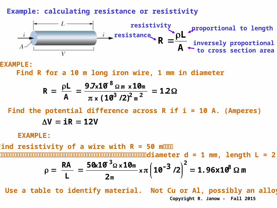
Example: calculating resistance or resistivity
A
LR
resistanceproportional to length
inversely proportional to cross section area
resistivity
EXAMPLE: Find R for a 10 m long iron wire, 1 mm in diameter
. )/(10
.
A
L R
2m
3-x
m xm.x21
2
1010792
8
Find the potential difference across R if i = 10 A. (Amperes)
V iR V 12
EXAMPLE:
Find resistivity of a wire with R = 50 mdiameter d = 1 mm, length L = 2 m
m. .96x10 /3-10
L
RA 8-
2 x
m
m x x
12
2
101050 3
Use a table to identify material. Not Cu or Al, possibly an alloy
Copyright R. Janow - Fall 2015
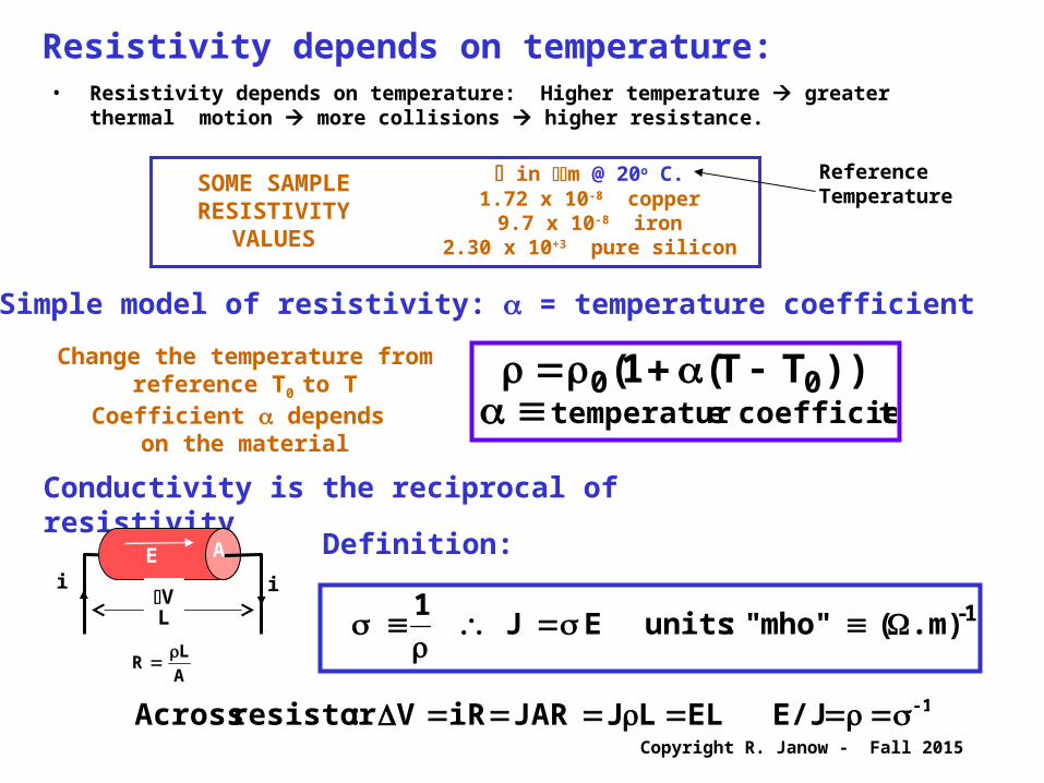
Resistivity depends on temperature:• Resistivity depends on temperature: Higher temperature greater
thermal motion more collisions higher resistance.
Conductivity is the reciprocal of resistivity
-1 E/J EL LJJARiRV :resistor Across
1- .m)( mho"" :units E J
1
i iV
E
L
A Definition:
A
L R
SOME SAMPLERESISTIVITY
VALUES
in m @ 20o C.1.72 x 10-8 copper
9.7 x 10⁻⁸ iron2.30 x 10+3 pure silicon
Reference Temperature
Change the temperature from reference T0 to TCoefficient depends
on the materialtcoefficien etemperatur
))TT((
00 1
Simple model of resistivity: = temperature coefficient

Copyright R. Janow - Fall 2015
Resistivity Tables
Copyright R. Janow - Fall 2015
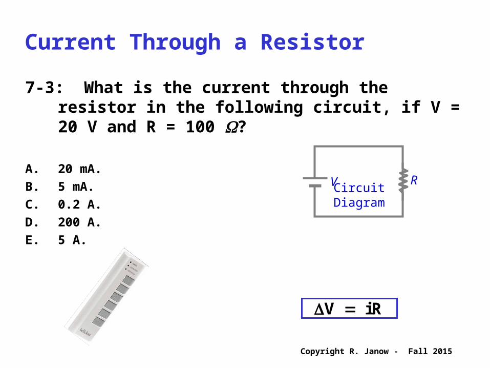
Current Through a Resistor
7-3: What is the current through the resistor in the following circuit, if V = 20 V and R = 100 ?
A. 20 mA.B. 5 mA.C. 0.2 A.D. 200 A.E. 5 A.
RV CircuitDiagram
R i V
Copyright R. Janow - Fall 2015
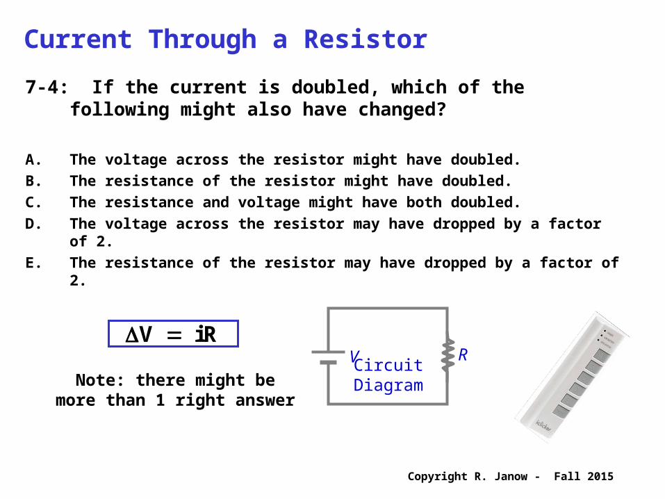
Current Through a Resistor
7-4: If the current is doubled, which of the following might also have changed?
A. The voltage across the resistor might have doubled.B. The resistance of the resistor might have doubled.C. The resistance and voltage might have both doubled.D. The voltage across the resistor may have dropped by a factor of
2.E. The resistance of the resistor may have dropped by a factor of 2.
RV CircuitDiagram
R i V
Note: there might bemore than 1 right answer
Copyright R. Janow - Fall 2015
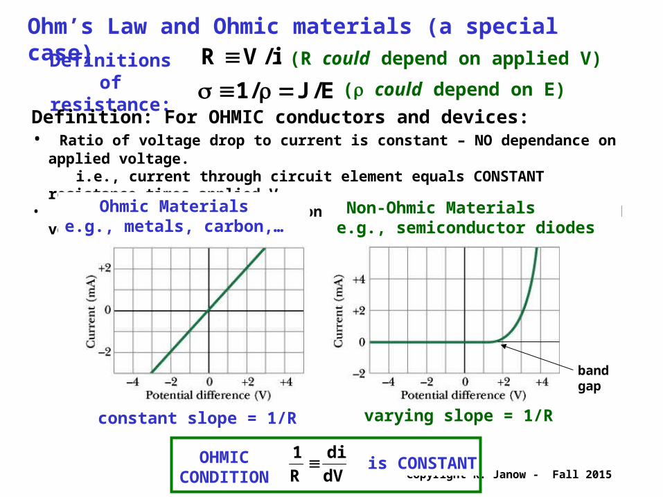
Ohm’s Law and Ohmic materials (a special case) Definitions of
resistance:i/VR (R could depend on applied V)
E/J/ 1 ( could depend on E)
Definition: For OHMIC conductors and devices:• Ratio of voltage drop to current is constant – NO dependance on applied voltage. i.e., current through circuit element equals CONSTANT resistance times applied V • Resistivity does not depend on magnitude or direction of applied voltage
Ohmic Materials e.g., metals, carbon,…
Non-Ohmic Materialse.g., semiconductor diodes
constant slope = 1/R varying slope = 1/R
band gap
OHMICCONDITION dV
di
R
1 is CONSTANT

Copyright R. Janow - Fall 2015
Resistive Loads in Circuits Dissipate Power
dt Vidq VdU
i
V
+i
-
LOAD
1
2
• Apply voltage drop V across basic circuit element (load)• Current flows through load which dissipates energy • An EMF (e.g., a battery) does work, holding potential V and current i constant by expending potential energy
/R VRi P iR V
Vidt
dq
dq
dU
dt
dU P dissipated Power
only resistors22
load anyfor[Watts]
As charge dq flows from 1 to 2 it loses P.E. = dU
- potential is PE / unit charge- charge = current x time
element absorbs power P=-Vi
1
2iV
+
-
1
2iV
-
+
element supplies power P= +Vi
1
2iV
+
-
1
2iV
-
+
Voltage rise:
+
-V
Active sign convention: Pabsorbed = dot product of Vrise with i
Note: Some EE circuits texts use passive convention: model voltage drops Vdrop as positive.

Copyright R. Janow - Fall 2015
EXAMPLE:
EXAMPLE:
EXAMPLE:

Copyright R. Janow - Fall 2015
Basic circuit elements have two terminals
Basic Circuit Elements and Symbols
1 2
Ideal basic circuit elements:
Generic symbol:
Active: voltage sources (EMF’s), current sourcesL
C Cor
R
Passive: resistance, capacitance, inductance
is
Ideal independent voltage source:• zero internal resistance• constant vs for any load
Ideal independent current source: • constant is regardless of load
vs
+
-E
+-vs
DCDC
batteryAC
Dependent voltage or current sources: depend on a control voltage or current generated elsewhere within a circuit

Copyright R. Janow - Fall 2015
Circuit analysis with resistances and EMFs
ANALYSIS METHOD: Kirchhoff’S LAWS or RULES
Current (Junction) Rule:
outin i i Charge conservation
Loop (Voltage) Rule: loop) (closed 0 V Energy conservation
i
V
slope= 1/R
RESISTANCE:
POWER:
OHM’s LAW:
yresistivit A
LR
i
VR
(resistor)2 RiP iV
dt
dU
dt
dWP
R is independent of V or i
CIRCUIT ELEMENTS ARE CONNECTED TOGETHER AT NODES
i
i1
i2
CIRCUITS CONSIST OF JUNCTIONS (ESSENTIAL NODES) ... and … ESSENTIAL BRANCHES (elements connected in series,one current/branch) i
Copyright R. Janow - Fall 2015
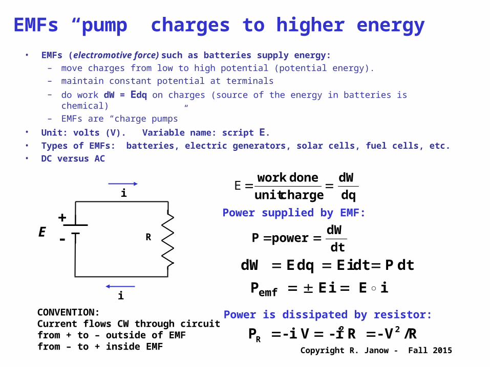
EMFs “pump” charges to higher energy• EMFs (electromotive force) such as batteries supply energy:
– move charges from low to high potential (potential energy).– maintain constant potential at terminals
– do work dW = Edq on charges (source of the energy in batteries is chemical) – EMFs are “charge pumps”
• Unit: volts (V). Variable name: script E.• Types of EMFs: batteries, electric generators, solar cells, fuel cells, etc.• DC versus AC
+- RE
i
i
CONVENTION:Current flows CW through circuitfrom + to – outside of EMFfrom – to + inside EMF
dq
dW
chargeunit
done work E
dt P dt i dq dW E E
i i Pemf
E E
dt
dW power P
R/V- R i- V i - P 22R
Power is dissipated by resistor:
Power supplied by EMF:

Copyright R. Janow - Fall 2015
• Zero internal battery resistance• Open switch: EMF = E no current, zero power• Closed switch: EMF E is also applied across load circuit• Current & power not zero
Ideal EMFdevice
R
MultipleEMFs
Assume EB > EA (ideal EMF’s) Which way does current i flow?• Apply kirchhoff Laws to find current• Answer: From EB to EA • EB does work, loses energy• EA is charged up• R converts PE to heat• Load (motor, other) produces motion and/or heat
Real EMFdevice
• Open switch: EMF still = E• r = internal EMF resistance in series, usually small ~ 1 • Closed switch:
• V = E – ir across load, Pckt= iV• Power dissipated in EMF Pemf = i(E-V) = i2r

Copyright R. Janow - Fall 2015
The Kirchhoff Loop Rule Generates Circuit Equations
• The sum of voltage changes = zero around all closed loops in a multi-loop circuit) • Traversing one closed loop generates one equation. Multiple loops may be needed.• A branch is a series combination of circuit elements between essential nodes.• Assume either current direction in each branch. Minus signs may appear in the result. • Traverse each branch of a loop with or against assumed current direction.• Across resistances, write voltage drop V = - iR if following assumed current direction. Otherwise, write voltage change = +iR. • When crossing EMFs from – to +, write V = +E. Otherwise write V= -E• Dot product i.E determines whether power is actually supplied or dissipated
Follow circuit from a to b to a, same direction as i
Potential around the circuit
EXAMPLE: Single loop (circuit with battery (internal resistance r)
0 iRirERr
Ei
EE
P = iE – i2r
Power in External Ckt
circuitdissipation
batterydrain
batterydissipation
P = iV = i(E – ir)
Copyright R. Janow - Fall 2015
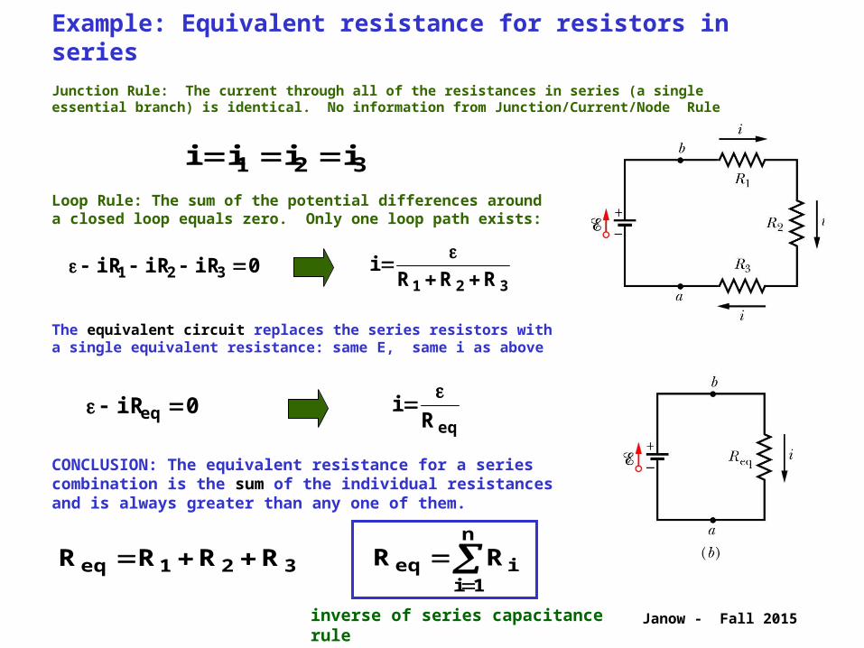
The equivalent circuit replaces the series resistors with a single equivalent resistance: same E, same i as above
Loop Rule: The sum of the potential differences around a closed loop equals zero. Only one loop path exists:
Example: Equivalent resistance for resistors in series
Junction Rule: The current through all of the resistances in series (a single essential branch) is identical. No information from Junction/Current/Node Rule
iiii 321
0321 iRiRiR
eqRi
iR eq 0
321 RRRi
321 RRRReq RR n
iieq
1
CONCLUSION: The equivalent resistance for a series combination is the sum of the individual resistances and is always greater than any one of them.
inverse of series capacitance rule

Copyright R. Janow - Fall 2015
Example: Equivalent resistance for resistors in parallel
Loop Rule: The potential differences across each of the 4 parallel branches are the same. Four unknown currents. Apply loop rule to 3 paths.
33
22
11 R
i ,R
i ,R
iEEE
321321
111
RRR i i i i E
321
1111
RRRReq
RR
n
i ieq
1
11
011 RiE 022 RiE 033 RiE
Junction Rule: The sum of the currents flowing in equals the sum of the currents flowing out. Combine equations for all the upper junctions at “a” (same at “b”).
eqRi
iR eq 0
The equivalent circuit replaces the series resistors with a single equivalent resistance: same E, same i as above.
CONCLUSION: The reciprocal of the equivalent resistance for a parallel combination is the sum of the individual reciprocal resistances and is always smaller than any one of them.
inverse of parallel capacitance rule
i not in these
equations
RR
RRR eq
21
21

Copyright R. Janow - Fall 2015
7-7: Four identical resistors are connected as shown in the figure. Find the equivalent resistance between points a and c.
A. 4 R.B. 3 R.C. 2.5 R.D. 0.4 R.E.Cannot determine from information given.
Resistors in series and parallel
R
R R
R
c
a
RR
n
i ieq
1
11 RR
n
iieq
1

Copyright R. Janow - Fall 2015
7-8: Four identical capacitors are connected as shown in figure. Find the equivalent capacitance between points a and c.
A. 4 C.B. 3 C.C. 2.5 C.D. 0.4 C.E. Cannot determine from information given.
Capacitors in series and parallel
C
C C
C
c
a
CC
n
i ieq
1
11 CC
n
iieq
1

Copyright R. Janow - Fall 2015
EXAMPLE:
EXAMPLE:
+-
R1= 10
R2= 7
R3= 8 E = 7 V
i
+-
E = 9 VR1 R2
i1 i2
i
i
Find i, V1, V2, V3, P1, P2, P3
Find currents and voltage drops
RR
RRR eq
21
21
Copyright R. Janow - Fall 2015
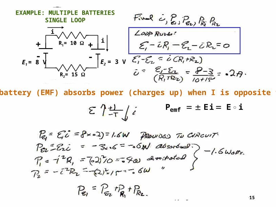
+-
+-
R1= 10
R2= 15
E1 = 8 V E2 = 3 V
i
i
EXAMPLE: MULTIPLE BATTERIESSINGLE LOOP
A battery (EMF) absorbs power (charges up) when I is opposite to E
i i Pemf
E E

Copyright R. Janow - Fall 2015
EXAMPLE: Find the average current density J in a copper wire whose diameter is 1 mm carrying current of i = 1 ma.
2amps/m
m3-
x
amps-3
1273 )10 x (.5
10
A
i J
2
Suppose diameter is 2 mm instead. Find J’:
2amps/m 318
4
J
A'
i J' Current i is unchanged
Calculate the drift velocity for the 1 mm wire as above? 28
x3
melectrons/ conduction#CuwheredCu 10 8.49 n ven J
s/mx...
1273
en
J v
xxxCud
82819
10379104981061
About 3 m/year !!
So why do electrical signals on wires seem to travel at the speed of light (300,000 km/s)?
Calculating n for copper: One conduction electron per atom
10 8.49
10 8.96 63.5
10 6.023 x 1 n
3melectrons/
28x
3
/m3
cm6
x 3
gm/cmxgm/mole
atoms/mole23
x atom/electronCu