Copyright by Karen Denise Kirk 2012
47
Copyright by Karen Denise Kirk 2012
Transcript of Copyright by Karen Denise Kirk 2012

Copyright
by
Karen Denise Kirk
2012

The Report Committee for Karen Denise Kirk
Certifies that this is the approved version of the following report:
Design, Fabrication, and Testing of a MEMS Z-Axis Directional
Piezoelectric Microphone
APPROVED BY
SUPERVISING COMMITTEE:
Neal A. Hall
Dean P. Neikirk
Supervisor:

Design, Fabrication, and Testing of a MEMS Z-Axis Directional
Piezoelectric Microphone
by
Karen Denise Kirk, B.S.
Report
Presented to the Faculty of the Graduate School of
The University of Texas at Austin
in Partial Fulfillment
of the Requirements
for the Degree of
Master of Science in Engineering
The University of Texas at Austin
May 2012

iv
Acknowledgements
I would like to express my gratitude to all those who have supported me during
the completion of my masters research at The University of Texas at Austin. First and
foremost, I would like to thank Dr. Neal Hall for his guidance, mentorship, and continual
encouragement during the project. I am indebted to both Dr. Hall for his financial
support and to the National Science Foundation for funding this research through an
awarded Graduate Research Fellowship, and I also would like to thank Dr. Amanda
Zappler for providing her expertise in hearing aid devices. I also acknowledge Caesar
Garcia and Guclu Onaran in their previous work on this project before I took ownership
of it. I would like to thank my colleagues, Michael Kuntzman, Nishshanka Hewa-
Kasakarage, Donghwan Kim, Dr. Sang-Soo Je, and Dr. Sang Yoon for their support
throughout the project. Finally, I would like to thank my family and friends for their
understanding and support.

v
Abstract
Design, Fabrication, and Testing of a MEMS Z-Axis Directional
Piezoelectric Microphone
Karen Denise Kirk, M.S.E.
The University of Texas at Austin, 2012
Supervisor: Neal A. Hall
Directional microphones, which suppress noise coming from unwanted directions
while preserving sound signals arriving from a desired direction, are essential to hearing
aid technology. The device presented in this paper abandons the principles of standard
pressure sensor microphones, dual port microphones, and multi-chip array systems and
instead employs a new method of operation. The proposed device uses a lightweight
silicon micromachined structure that becomes “entrained” in the oscillatory motion of air
vibrations, and thus maintains the vector component of the air velocity. The mechanical
structures are made as compliant as possible so that the motion of the diaphragm directly
replicates the motion of the sound wave as it travels through air. The microphone
discussed in this paper achieves the bi-directionality seen in a ribbon microphone but is
built using standard semiconductor fabrication techniques and utilizes piezoelectric
readout of a circular diaphragm suspended on compliant silicon springs. Finite element
analysis and lumped element modeling have been performed to aid in structural design
and device verification. The proposed microphone was successfully fabricated in a

vi
cleanroom facility at The University of Texas at Austin. Testing procedures verified that
the resonant frequency of the microphone, as expected, was much lower than in
traditional microphones. This report discusses the theory, modeling, fabrication and
testing of the microphone.

vii
Table of Contents
Table of Contents .................................................................................................. vii
List of Tables ......................................................................................................... ix
List of Figures ..........................................................................................................x
Chapter 1: Introduction ............................................................................................1
Chapter 2: Theory of Operation ...............................................................................3
2.1 Motivation ..............................................................................................3
2.2 Current Competing Technology ............................................................3
2.3 Proposed Microphone Overview ...........................................................4
2.4 Background of Ribbon Microphones .....................................................6
2.5 Why Piezoelectric Readout? ..................................................................7
Chapter 3: Modeling ................................................................................................9
3.1 Lumped Element Modeling ...................................................................9
3.2 Finite Element Analysis .......................................................................12
Chapter 4: Fabrication............................................................................................15
4.1 Fabrication Summary ...........................................................................15
4.2 Unique Electrode Split of Proposed Microphone ................................18
Chapter 5: Testing Results .....................................................................................22
5.1 Testing with a Transimpedance Amplifier ..........................................22
5.2 Test 1 for Sound Sensing, Microphone Behavior ................................23
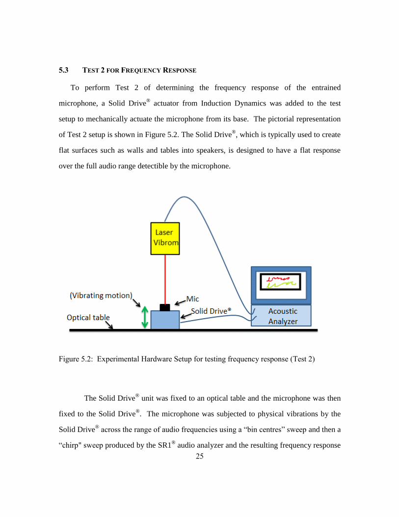
5.3 Test 2 for Frequency Response ............................................................25
5.4 Test 3 for Piezoelectric Readout ..........................................................27
5.5 Discussion of Test Results ...................................................................27
Chapter 6: Discussion and Conclusion ..................................................................30
6.1 Current Achievements .........................................................................30
6.2 Design Improvements in Process .........................................................31
6.3 Goals for the Final Design ...................................................................33

viii
6.4 Summary of Future Challenges ...........................................................33
References ..............................................................................................................35
Vita .......................................................................................................................37

ix
List of Tables
Table 2.1: Comparison of General Piezoelectric Properties ....................................8
Table 3.1: Lumped Element Terms Summary .......................................................11
Table 3.2: Simulated Resonant Frequencies for the Entrained Microphone .........14

x
List of Figures
Figure 2.1: Photorealistic images of the piezoelectric microphone device .............5
Figure 2.2: Packaging elements of microphone .......................................................5
Figure 3.1: Lumped Element Circuit Model for the Entrained Microphone .........10
Figure 3.2: Combined Mechanical Equivalent Circuit ..........................................10
Figure 3.3: Simulation of piezoelectric sensing elements .....................................12
Figure 4.1: Cross-sectional schematic of the entrained microphone ....................16
Figure 4.2: Summarized Microphone Fabrication Flow ........................................17
Figure 4.3: Sketches of a top-side view and piezoelectric “split” of the entrained
microphone .......................................................................................19
Figure 4.4: SEM of an entrained microphone spring structure .............................20
Figure 4.5: General layer stack for piezoelectric entrained microphone (top) and
dimensioned close-up view (bottom) ................................................21
Figure 5.1: Demonstration of the acoustic frequency response of the complete
microphone system presented in Figure 2.2(a). ................................23
Figure 5.1: Experimental Hardware Setup for testing sound detection capability 24
Figure 5.2: Experimental Hardware Setup for testing frequency response ..........25
Figure 5.3: Vibration frequency response of the entrained microphone ..............26
Figure 5.4: Laboratory setup for testing the entrained microphone .......................29
Figure 6.1: FEA of the next generation of piezoelectric entrained microphones,
featuring four springs and a 1.5 kHz resonance. ...............................31
Figure 6.2: Electric potential in the piezoelectric material at the end of a microphone
spring (red is highest down to a dark green). ....................................32

1
Chapter 1: Introduction
Directional microphones, which suppress noise coming from unwanted directions
while preserving sound signals arriving from a desired direction, are essential to hearing
aid technology. Directionality is one of the primary means by which signal-to-noise ratio
may be improved, which in turn improves speech intelligibility [1]. Current directional
microphones either require two “ports” (i.e. sound inlet/outlets) or they consist of two or
more omnidirectional microphones placed in an array. Both of these options are outside
of the current capabilities of MEMS fabrication techniques. Cost and space limitations on
today’s smaller-than-ever electronics fuel the motivation to design a single-chip
inherently directional MEMS microphone.
There are a number of other potential applications for directional sound sensing in
smart phones, tablets, and computers. For example, one could place the directional
MEMS microphone in a smart phone, and with the proper signal processing the phone
could serve as a “conference call” device, capable of picking up the sound of a person
speaking anywhere in the room. Perhaps the greatest benefit to incorporating directional
microphones in consumer electronics is the same as in hearing aids: improved signal-to-
noise ratio, especially when trying to communicate in loud environments.
Directional microphone technology is not a new idea. Ribbon microphones, which
were first developed in the 1920’s, are inherently bi-directional (producing a “figure 8”
pattern) due to a thin film ribbon that is placed between two poles of a magnet to generate
voltage[2]. However the requirements of having the long ribbon, a moving coil, and a
substantial magnetic force have thus far required that these devices be large, fragile, and
costly[3]. The microphone discussed in this paper achieves the bi-directionality of a
ribbon microphone but is built using standard semiconductor fabrication techniques.

2
Further, it forgoes the traditional ribbon microphone structures and utilizes piezoelectric
readout of a circular diaphragm suspended on compliant silicon springs. This paper
discusses the theory, modeling, fabrication and testing of the microphone.

3
Chapter 2: Theory of Operation
2.1 MOTIVATION
The inspiration behind the design of this novel microphone draws from the fact
that a sound wave, in addition to having a scalar pressure component, contains oscillatory
vibrations of the air in the direction of sound wave propagation. For typical speech
sounds, the amplitudes of these oscillatory vibrations are large enough to be felt by
touching the throat while vocalizing. Traditional microphones are essentially pressure
sensors that measure the sound pressure of incoming sound signals, and in such devices
all the information about the direction of sound propagation is lost. Further, pressure
microphones are not impedance matched, and therefore (i) reflect the majority of the
available sound power for measurement and (ii) have diaphragms which move much less
than the actual air vibrations. Capturing the directionality in sound sensing is a very
important capability, especially in hearing aid technology. Hearing aid directional
technology (using multi-chip and multi-port setups as described in Section 2.2 below) has
effectively improved the signal-to-noise ratio (SNR) immensely over previous designs, so
the standards that a single-chip microphone must achieve have been established.
2.2 CURRENT COMPETING TECHNOLOGY
Presently, directional microphones in hearing aid systems either require two
separate “ports” (i.e. sound inlet or outlets) or they consist of two or more
omnidirectional microphones placed in an array along the earpiece [1]. The former
option is outside of the current capabilities of MEMS fabrication techniques, and the
latter option suffers increased power consumption and sound distortion resulting from the
necessary complex, non-ideal configuration of the additional microphones. The latter

4
approach is also limited by the extent to which the phase response of elements across the
array can be matched, and stay matched across a wide range of operating temperatures.
Cost and size demands by today’s smaller-than-ever electronics fuel the motivation to
design a single-chip inherently directional MEMS microphone.
2.3 PROPOSED MICROPHONE OVERVIEW
The device presented in this paper abandons the principles of standard pressure
sensor microphones, dual port microphones, and multi-chip array systems and instead
employs a new method of operation. The proposed device uses a lightweight silicon
micromachined structure that becomes “entrained” in the oscillatory motion of air
vibrations. The mechanical components are made as compliant as possible so that the
motion of the diaphragm directly replicates the motion of the sound wave as it travels
through air. Figures 2.1(a) and (b) show photorealistic images of the entrained
microphone chip (created in SolidWorks). Figure 2.1(a) shows the full die image with
square outer dimensions of 2 mm by 2 mm, and Figure 2.1(b) is a close-up version
showing the topography of the electrodes (light gray) and piezoelectric material (white)
on circumferential winding springs. The microphone diaphragm is suspended in air by
these thin, highly compliant weaving spring structures that serve to lower both the device
stiffness and resonant frequency. The significance of the unusually low resonance
frequency is discussed in Section 5.1. The proposed microphone housing structure
includes a top and bottom opening to allow sound and air to surround and travel past the
diaphragm. Figures 2.2(a) and (b) show a concept sketch of the packaging elements and a
side view schematic including the air flow, respectively. The final microphone setup will
be fully integrated with a custom designed printed circuit board (PCB) inside the capsule.

5
Figure 2.1: Photorealistic images of the piezoelectric microphone device
(a) Concept sketch of microphone
package (case and PCB)
(b) Cross view of package with acoustic
particle displacement indicated
Figure 2.2: Packaging elements of microphone
The proposed method of directly imitating air vibration velocity contrasts the
functionality of traditional microphones that simply reflect sound pressure. Two notable
(a) Isometric view of microphone
die
(b) Close up view of spring structures

6
benefits of a velocity sensing design are that 1) the amplitude of the entrained diaphragm
motion is much larger than that of a traditional pressure microphone (by more than ten
times), allowing for greater acoustic sensitivity and thus higher fidelity, and 2) the
oscillatory mechanical vibrations are only enacted in the direction of sound propagation,
so the diaphragm only responds in the direction normal to the incoming sound wave.
Thus, the structure is inherently directional and has the capability of focusing on an event
of interest while filtering out unwanted noise from other directions. This phenomenon
allows for highly desired audio capabilities such as noise cancellation and sound source
localization [1].
2.4 BACKGROUND OF RIBBON MICROPHONES
While the proposed microphone utilizes piezoelectric sensing in a novel method
of operation, when tested, it in fact exhibits very similar behavior in operating principle
to many large-scale ribbon microphones [4-6], without requiring any of the traditional
ribbon microphone structures. Traditional ribbon microphones consist of a long,
corrugated metallic ribbon that produces a voltage when actuated in the direction
perpendicular to its length. Ribbon microphones, which were first developed in the
1920’s, are inherently bi-directional (producing a “figure 8” pattern) due to a thin film
ribbon that is placed between two poles of a magnet to generate voltage [2],[7]. Ribbon
microphones are often preferred in many live music and recording applications because
of the high quality and frequency response shape. While the low-stress configuration of
the ribbon microphone diaphragm allows for smooth and natural transfer of sound,
shortcomings of the traditional structures include low sensitivity and requirements for
very complex and fragile features [8]. Furthermore, the requirements of having the long

7
ribbon, a moving coil, and a substantial magnetic force have thus far required that these
devices be large, fragile, and costly. In 2009, a research team presented a miniature
(MEMS) version of the ribbon microphone which uses a symmetric conductor voice coil
deposited on polymer material [9]. The microphone required a large external magnetic
field to function and the sensitivity was highly dependent on the producible magnetic flux
density. The microphone discussed in this paper achieves the bi-directionality of a ribbon
microphone but is built using standard semiconductor fabrication techniques and simple
piezoelectric sensing structures.
2.5 WHY PIEZOELECTRIC READOUT?
One benefit of piezoelectric sensing is that it is appropriate for a relatively large
range of displacement magnitudes. The dynamic range of the microphone sensing
elements may be defined as the sound pressure level region that is both above the
thermal-mechanical limit and below the distortion limit [14]. There is a separate dynamic
range that corresponds to the capabilities of the vibrating mechanical structures, which
may be defined as the range of displacements between the low level noise limit and high
level distortion limit. Selection of transduction principle should be made such that the
overlap between these two dynamic ranges is maximized. In the case of the proposed
microphone, the mechanical structures are designed to show displacements on the order
of hundreds of nanometers, which are much larger than other high-stiffness MEMS
microphone designs. Thus, a transduction method that can accommodate a relatively high
thermal-mechanical displacement and a large distortion displacement is ideal. If MEMS
microphones that use optical and capacitive transduction techniques are subjected to such
high signal amplitudes, distortion or “clipping” often results. Piezoelectric material,

8
however, can much better withstand the high dynamic range and is appropriate for the
motion in question.
Piezoelectric sensitivity varies depending on the type of material and the method
of deposition. Table 2.1 shows a comparison of the most common piezoelectric materials
(adapted from [15]). Lead-zirconate-titanate (PZT) material has a very large d33
coefficient and dielectric constant, which corresponds to a larger output capacitance [15]
and thus was the chosen material for the proposed device.
Table 2.1: Comparison of General Piezoelectric Properties
Type of
Piezoelectric
d33 coeff.
(pC/N)
Young’s
Mod.
(GPa)
Poisson’s Ratio
(kg/m3)
Dielectric constant
PZT 290 96 7.7 1300
AlN 3.4 330 3.26 10.5
ZnO 12 210 5.6 12.7
PVDF (Hylar)* -16.5 1.1 0.29 7.72
* Data from reference [16]
Piezoelectric sensors are particularly convenient in small electronics because no
external power is required for the sensors to function, which adds to the simplicity of the
device. These sensors also have an advantage of being thermally stable over a wide
range of temperatures [17, 18]. Further, piezoelectric sensing is the most rugged type of
MEMS transduction technique and is more likely to survive harsh environmental
conditions of hearing aid “hits” and cell phone “drops.”

9
Chapter 3: Modeling
To design the dimensions and geometry of the entrained microphone and for
design verification and validation, a set of modeling techniques was developed. These
techniques include lumped element modeling, frequency response analysis, and Finite
Element Analysis (FEA) modal and harmonic tests.
3.1 LUMPED ELEMENT MODELING
A lumped element model (LEM) may be used to approximate the physical,
electrical and acoustical components of the microphone system as a combination of
standard electrical components. Each domain (acoustic, electric, and mechanical in the
case of the entrained microphone) can then be equated to an electrical equivalent,
allowing for a single equivalent circuit to be derived which represents the entire system
[4]. Lumped modeling is helpful in calculating desired impedance values such as the
input impedance looking into the device. In acoustical models, LEM is valid when the
wavelengths of the impendent signals are significantly longer than any relative dimension
of the device. This requirement is easily met by the proposed MEMS microphone device
in the full audio frequency range. A diagram of the resulting lumped circuit model is
shown in Figure 3.1, and the equivalent combined mechanical system is shown in Figure
3.2. The lumped element diagram in Figure 3.1 is divided into three major domains: the
capsule (acoustical), the diaphragm (mechanical) and the PZT sensing elements
(piezoelectric).

10
Figure 3.1: Lumped Element Circuit Model for the Entrained Microphone
Figure 3.2: Combined Mechanical Equivalent Circuit for the Entrained Microphone
Once an acoustic signal approaches the microphone capsule, the sound wave first
encounters the top sound inlet, represented by the viscous resistance of air through the
top port (Raptop) and an acoustical mass of air (Maptop). The air flow that escapes from
the front to the backside of the device is represented by a leakage resistor (RL). Inside the
casing, the sound wave actuates the diaphragm into motion and can be represented by
mechanical elements of the diaphragm’s mass (Md), compliance provided by the spring

11
structures (Cm), and mechanical resistance of the sensing structure due to material losses
and structural damping (Rm). The air cavity compliances above and below the diaphragm
are neglected in this model. The diaphragm resistance usually may be neglected as a
small term in comparison to the mass and capacitance, and to the other resistances in the
network. The velocity of the diaphragm generates a voltage in the piezoelectric thin film
sensing material due to the resulting strain in the diaphragm “springs.” This phenomenon
is represented by a blocked electrical capacitance (Ceb), a dielectric loss resistance (Re),
and a transformer ratio (φ). In the design phase, the blocked electrical capacitance and
transformer ratio can be modeled and computed using material properties of the film and
the geometry of the spring and sensing structure. They may also be determined
experimentally. The LEM presented in Figure 3.1 may also be used for a noise floor
analysis by including a voltage noise generator in series with the model’s resistors. Table
3.1 below summarizes the lumped element terms used in the analysis of the piezoelectric
microphone.
Table 3.1: Lumped Element Terms Summary
Term Description
ΔP Pressure drive
Raptop & Maptop Resistance and mass through top sound inlet
Rapbott & Mapbott Resistance and mass through bottom inlet
RL Leakage resistance
Ad Diaphragm area
Rm & Md Resistance (structural loss) and mass of diaphragm
Cm Compliance of diaphragm structure
Ceb Blocked electrical capacitance
Re Dielectric loss resistance
V Voltage readout from piezoelectric sensing elements

12
3.2 FINITE ELEMENT ANALYSIS
Finite element analysis (FEA) models were created for the entrained microphone
using the program Analysis System (ANSYS). FEA provides a method of determining
how a structure reacts to certain loading conditions by taking into account the structure’s
geometries and material properties. One of the greatest advantages of FEA is the rapid
analysis of complex structures that contain elements in multiple domains (e.g. electrical,
thermal, mechanical, or piezoelectric). For the proposed microphone device, FEA
modeling was used to determine important characteristics such as device resonant
frequency, areas of maximum displacement and stress, and voltage readout amplitude. A
microphone model was constructed that includes elements of electrical, piezoelectric, and
mechanical elements. A screenshot of a model showing electric potential is shown in
Figure 3.3. Near the bottom of the image, the piezoelectric sensing element layer in blue
can be seen on top of the diaphragm structures.
Figure 3.3: Simulation of piezoelectric sensing elements

13
A modal analysis of the microphone was performed to simulate the resonant
frequencies of the first four modes of the mechanical structure. The model was also used
to determine the regions of maximum stress along the winding spring structures.
Piezoelectric elements produce the highest voltage signal in regions of greatest stress, so
the orientation and extension of the PZT sensing elements for the proposed microphone
were planned using the stress simulation results. Table 3.2 shows a list of the first four
device resonant frequencies, a description of the motion type and an image depiction of
the direction of motion indicated by color spectrum. The primary resonant frequency
value in Table 3.2 is lower than that of most MEMS microphones, and the significance
for this is discussed further in Chapter 5. The color red indicates a region which reaches
the maximum displacement amplitude and blue indicates a region of minimum
displacement, with a progressive spectral color change in between.

14
Table 3.2: Simulated Resonant Frequencies for the Entrained Microphone
Set Frequency
(Hz)
Motion Description Image Depiction
1 4130.9
Full z-direction
displacement perpendicular
to plane of the diaphragm
2a 6618.1
Structural rotation about the
x-axis (parallel to
diaphragm plane)
2b 6618.1
Structural rotation about the
y-axis (parallel to
diaphragm plane)
3a 11651
Displacement along x-
direction, in-plane with
diaphragm
3b 11651
Displacement along y-
direction, in-plane with
diaphragm
4 18794 Pure rotation around the
vertical out-of-plane z-axis

15
Chapter 4: Fabrication
4.1 FABRICATION SUMMARY
The microphone fabrication was performed in the Microelectronics Research
Center cleanroom facility at The University of Texas at Austin, Pickle Research Campus.
The fabrication process utilized common semiconductor integrated circuit fabrication
techniques and a sol-gel lead zirconate titanate (PZT) deposition process. Figure 4.1(b)
shows the cross-sectional schematic of the entrained microphone as denoted in Figure
4.1(a) with the important features labeled. Described here is a summarized version of the
fabrication flow used to build the entrained microphone. A silicon-on-insulator (SOI)
wafer was chosen for processing so that the buried silicon dioxide could serve as an etch
stop for the final Bosch process. First, plasma-enhanced chemical vapor deposition
(PECVD) was performed on both sides of the four inch SOI wafer using an Oxford
Instruments Plasma Lab 80+ system to deposit silicon dioxide layers (1.2 µm of on top of
the epitaxial layer and 3 µm on the backside) to serve as etch masks. PECVD, which is a
low temperature process, was performed on the wafer instead of traditional furnace
oxidation of silicon to reduce the internal thermal stress between the silicon and silicon
dioxide layers. Thermal stress is a common concern in MEMS fabricated thin films
because the difference in thermal coefficients of expansion causes structures to deform or
break, and the problem became significant on the wafers which were oxidized. Next, a
100 nm layer of titanium was deposited on the top of the wafer and oxidized into TiO2 at
680°C in a furnace to serve as a diffusion barrier against the lead components in the PZT
sensor material.

16
(a) Die top view with cross-
section
(b) Labeled cross-sectional view of microphone
Figure 4.1: Cross-sectional schematic of the piezoelectric entrained microphone
A photoresist layer was then patterned on the wafer using standard lithography
techniques with an EVG620 mask aligner for the bottom electrodes and 80 nm of
platinum followed by 100 nm of titanium were sputtered on the wafer using a Cooke
Ebeam/Sputter Deposition System. The titanium was sputtered in a DC sputter head and
the platinum was deposited with an RF sputter head. The electrode pattern was then
realized via a lift-off process. The titanium layer serves as a necessary adhesion layer for
the platinum, which is known to produce quality readout of PZT. 1.2 µm of 52/48 PZT
was then deposited on the wafer via a repeating sol-gel and annealing process, and the top
electrodes were patterned and lift off was performed in the same manner and thicknesses
as the bottom electrode. The PZT layer was then wet-etched using a 100:10:1 ratio of DI
Water:HCl:HF and the platinum top electrodes served as the mask during the PZT wet
etch.
A photoresist mask was patterned on top of the wafer to cover the diaphragm and
spring structures and reactive ion etching (RIE) was performed on the top of the wafer to

17
etch through the TiO2 and the PECVD SiO2 layer. A deep reactive ion etch (DRIE)
process was used to etch through the top epitaxial silicon, which is 10 µm thick, and
finally the buried SiO2 layer was etched with RIE. This etch completed the “cut-outs” for
the diaphragm and spring structures that are supported by the carrier silicon (handle
layer). The top-side photoresist was then removed and a thick back-side photoresist
pattern was created as a mask for the Bosch process. The backside SiO2 was etched with
RIE and the carrier silicon was etched through using DRIE to realize the microphone
device. A fabrication flow summary is presented in Figure 4.2 below.
Figure 4.2: Summarized Microphone Fabrication Flow

18
4.2 UNIQUE ELECTRODE SPLIT OF PROPOSED MICROPHONE
Abandoning the standard magnetic “ribbon and coil” structures in favor of
piezoelectric readout proves advantageous in the proposed microphone design for several
reasons. Piezoelectric readout in MEMS is very common, especially in accelerometers
and microphones [10-13]. In this device, the desired component to measure is diaphragm
velocity, which is discussed further in Chapter 5, rather than diaphragm displacement.
Using piezoelectric material, it is possible to directly read a short circuit current as
opposed to an open circuit voltage. Short circuit current is directly proportional to
diaphragm velocity, whereas open circuit voltage is directly proportional to diaphragm
displacement.
Electrode isolation is achieved by splitting the electrode traces immediately
beyond the spring region and keeping all top and bottom electrodes separated via a
custom-designed PCB. Figure 4.3(a) shows a top-view sketch, with silicon regions in
light gray, back side etch opening regions in dark gray, and piezoelectric regions in light
and darker tan. A sketch of the piezoelectric electrode “split” is shown in Figure 4.3(b)
and the region is indicated from the arrow in Figure 4.3(a). Figure 4.3(c) shows a
microscope image of a real device electrode split. The bright yellow color is the
electrode region, the orange color is the top titanium oxide surface, and the dark regions
are the etched regions for the springs. Note that for the electrode that splits to the left in
Figure 4.3(c), piezoelectric thickness gives it an additional topography, which may be
seen by the dark outline.

19
(a) Top-view sketch, with
silicon regions in light gray,
back side etch opening in
dark gray, and piezoelectric
regions in light and darker
tan
(b) Sketch of the piezoelectric electrode “split”
- close-up of the encircled region in (a)
(c) Micrograph of an electrode split and spring etch
Figure 4.3: Sketches of a top-side view and piezoelectric “split” of the entrained
microphone
Scanning electron microscope (SEM) images were taken that demonstrate the
regions of the etched springs, deposited electrodes and material layers of the entrained
microphone. An image of the microphone magnified 500 times may be seen in Figure

20
4.4. Shape deformations are seen in the springs due to tension from the weight of the
diaphragm and from the pressures caused by the microscope’s vacuum system. The
electrode region may be seen as the light gray material on the outer-third length of the
spring and extending off towards the bottom of the image. The piezoelectric material is
not clearly visible in this image.
Figure 4.4: SEM of an entrained microphone spring structure

21
The final layer stack with corresponding layer thicknesses is shown in Figure 4.5.
For the top and bottom electrodes, the titanium layer is deposited before the platinum
layer to improve platinum adhesion (80 nm titanium and 100 nm platinum).
Figure 4.5: General layer stack for piezoelectric entrained microphone (top) and
dimensioned close-up view (bottom)

22
Chapter 5: Testing Results
5.1 TESTING WITH A TRANSIMPEDANCE AMPLIFIER
In most common piezoelectric based microphones and accelerometers, the
amplifier configuration consists of a charge amplifier which produces a buffered output
voltage proportional to the mechanical structure’s displacement. However, for the
readout of the entrained microphone piezoelectric electrodes, a current-to-voltage
transimpedance amplifier (TIA) is used that has near-zero input impedance. The
structure’s pressure drive (ΔP) has a j*ω dependence. Above the structural resonance of
the mechanical system, the mechanical impedance is dominated by the mass of the
structure and thus also has a j*ω dependence. The velocity of the device is found by
taking the ratio of the pressure drive to the mechanical impedance, which implies that the
two j*ω terms cancel and the microphone’s velocity above resonance is inherently flat
with changes in frequency. Since the velocity can be directly measured by reading out
current from the TIA, the resulting measured acoustic frequency response will be flat
above resonance. A simulated frequency response for a device with a 150Hz resonance
is shown in Figure 5.1.
This phenomenon explains the motivation for designing the microphone with an
unusually low mechanical resonant frequency. In the current proposed proof of concept
entrained microphone, the resonant frequency is around 4 kHz, and the next generation of
microphone designs will feature even lower resonant frequencies and more compliant
spring structures (as described further in the Discussion and Conclusion section).

23
Figure 5.1: Demonstration of the acoustic frequency response of the complete
microphone system presented in Figure 2.2(a).
5.2 TEST 1 FOR SOUND SENSING, MICROPHONE BEHAVIOR
Three tests were performed to evaluate the behavior of the entrained microphone.
First, the structural vibrations of the diaphragm and springs were measured to determine
whether the mechanical displacement of the diaphragm was sufficient to detect acoustic
signals. Second, the resonant frequency and frequency response of the device were
determined using mechanical actuation techniques. Third, properties of the piezoelectric
film were evaluated using electrical admittance spectroscopy.
Figure 5.1 shows a schematic diagram of the experimental setup used for
characterization of the piezoelectric entrained microphone (Test 1). The microphone was

24
packaged and mounted securely onto a fixed surface that was secured to an optical table.
A small speaker was set up facing the microphone to provide acoustical actuation in order
to verify that the magnitude of the diaphragm vibrations was sufficient to detect the
sound signals coming from the speaker. A 100 mV, 5000 Hz sinusoidal signal was
applied to the speaker and the amplitude of the diaphragm vibrations was recorded using
a Portable Digital Vibrometer (PDV-100) made by Polytec Incorporated. This is shown
as the “Laser Vibrom” image, with a red laser beam directed downward onto the
vibrating microphone diaphragm. The vibrometer is calibrated to produce a voltage
output that is proportional to the detected velocity perpendicular to the laser beam. The
laser vibrometer signal was connected to a SR1® Stanford Research Systems acoustic
analyzer, which has a computer user interface. It was verified that the microphone
diaphragm vibrations due to a 100 mV signal were of a magnitude detectible by the
vibrometer system.
Figure 5.1: Experimental Hardware Setup for testing sound detection capability (Test 1)
25
5.3 TEST 2 FOR FREQUENCY RESPONSE
To perform Test 2 of determining the frequency response of the entrained
microphone, a Solid Drive® actuator from Induction Dynamics was added to the test
setup to mechanically actuate the microphone from its base. The pictorial representation
of Test 2 setup is shown in Figure 5.2. The Solid Drive®, which is typically used to create
flat surfaces such as walls and tables into speakers, is designed to have a flat response
over the full audio range detectible by the microphone.
Figure 5.2: Experimental Hardware Setup for testing frequency response (Test 2)
The Solid Drive® unit was fixed to an optical table and the microphone was then
fixed to the Solid Drive®. The microphone was subjected to physical vibrations by the
Solid Drive® across the range of audio frequencies using a “bin centres” sweep and then a
“chirp" sweep produced by the SR1® audio analyzer and the resulting frequency response

26
was measured with the laser vibrometer. The vibrometer information was read back into
the SR1® audio analyzer in the form of a Fast-Fourier Transform (FFT) analysis. Bin
centres analysis is a powerful tool that produces a high resolution frequency response in
the time needed for a single FFT buffer, where the signals are specifically constructed of
frequency components at certain FFT bin centre frequencies. The actual frequency
response with a resonance peak at 4.71 kHz was produced using these techniques and is
shown in Figure 5.3.
Figure 5.3: Vibration frequency response of the entrained microphone (Test 2)

27
5.4 TEST 3 FOR PIEZOELECTRIC READOUT
Electrical admittance spectroscopy measurements were used to evaluate the PZT
quality of the entrained microphone device. Admittance spectroscopy techniques can be
used as a powerful way to determine resonant frequency, quality (Q), device capacitance,
coupling strength, and the piezoelectric material properties. After the piezoelectric
material is poled, the response shows a slope of 20 dB/decade in the region where the
admittance is dominated by the electrical capacitance. At the device resonance, a “spike”
is produced which can be used to determine PZT characteristics. A detailed paper
describing the successful use of this testing method on piezoelectric cantilever beams is
being submitted at the time of this report’s release, but the method’s theory will not be
discussed in depth here. The entrained microphone device demonstrated the 20
dB/decade slope, indicating successful poling, but the signal produced by the electrodes
was too small to gather information from the data “spike,” as discussed in the next
section.
5.5 DISCUSSION OF TEST RESULTS
Three tests were performed to evaluate the behavior of the entrained microphone
proposed in this report. First, the structural vibration magnitudes were measured to
determine whether the mechanical displacement of the diaphragm was sufficient to detect
an acoustic signal. A 100 mV signal was used to verify that the resonating structures
were in fact sensitive enough to detect a low but audible acoustic signal. Second, the
resonant frequency of the device was determined using mechanical actuation techniques
and a laser vibrometer (as described in Section 5.3). This measurement verified that the
resonant frequency of the microphone, as expected, was lower than in traditional
microphones, serving as a proof-of-concept device that validates the fabrication

28
techniques. Third, the piezoelectric readout signal was evaluated using admittance
spectroscopy as mentioned in Section 5.4. While the admittance measurements upheld
the expected 20 dB per decade slope, in this phase of design, the amount of signal
produced by the microphone electrodes was too small to be resolved above the noise
floors of both the device and the TIA.
After further investigation it was determined that the piezoelectric signal was
unresolvable due to area scaling effects for the entrained microphone spring structures.
Electrical admittance measurements of piezoelectric readout have been successful on
similarly fabricated, larger-scale piezoelectric beams, so the PZT quality itself has been
verified previously. It is likely that the PZT undercut during the wet etching process is
another significant factor as to why the piezoelectric signal could not be detected, but this
problem may be resolved by increasing the electrode areas. As discussed in Chapter 6 to
follow, our next intermediate design step is to significantly increase the area of the
electrodes on a set of entrained microphone devices to evaluate the quality and behavior
of the piezoelectric sensing elements on top of microphone springs.
Figure 5.4(a), (b), (c) and (d) are photos of the laboratory setup used to measure the
microphone device.

29
(a) Acoustic test setup where a small speaker is
directed at the piezoelectric microphone.
The speaker actuates the fixed microphone
to measure behavior (Test 1)
(b) Microphone attached to the Solid Drive
®
actuator with vibration readout detected
by the PDV100 vibrometer (Test 2)
(c) For Test 3, the microphone was placed on a
custom PCB inside a TIA (metal box
structure) and the readout was performed
on a SR1® Audio Analyzer
(d) Close-up view of the device on PCB
(center) in the open TIA box
Figure 5.4: Laboratory setup for testing the entrained microphone

30
Chapter 6: Discussion and Conclusion
6.1 CURRENT ACHIEVEMENTS
The microphone presented in this report has been designed to be an inherently Z-
directional MEMS microphone, which is an achievement that is advantageous in
applications such as noise cancellation and sound source localization. A finite element
model of the piezoelectric entrained microphone has been proposed which can be used
for design purposes. The microphone is designed to have a low resonance frequency and
the sensing bandwidth is set above the resonance frequency. This was achieved by
suspending the diaphragm on long winding spring structures and making the sensing
structures highly compliant.
The entrained microphone consists of a circular diaphragm that is 1 mm in
diameter and 10 µm thick, winding silicon “spring” structures that host piezoelectric
sensing electrodes, and a handle structure made out of carrier silicon via a Bosch process.
The microphone has been constructed in a cleanroom facility at The University of Texas
at Austin using standard semiconductor microfabrication techniques out of a silicon-on-
insulator (SOI) wafer. The overall capsule size is 2 mm x 2 mm x 1 mm, making the
proposed microphone device consistent in size with the smallest microphones
commercially available today. This microphone served as a solid proof-of-concept study
of the fabrication process. The fabrication procedures and learning established during
this current microphone generation will again be used to build the next generation of
microphones.

31
6.2 DESIGN IMPROVEMENTS IN PROCESS
It is important to verify the functionality and quality of the PZT electrode material
on the entrained microphone structures, so an intermediate design step is planned that
includes the fabrication of a larger-than-MEMS set of entrained microphones. Mask files
containing designs with electrodes over ten times larger than the current design have been
ordered and fabrication is in progress (at the time of this report’s release). Finite element
analysis has been performed on the newly designed structures. The new set contains
single-winding springs (roughly 300 um wide) and much larger piezoelectric electrode
areas. Figure 6.1 below shows one of the designs which has four circumferential springs,
vibrating in its primary resonance at a resonant frequency of 1.5 kHz. It is expected that
these devices will show a significantly larger signal readout that will be resolvable by the
current TIA test configuration.
Figure 6.1: FEA of the next generation of piezoelectric entrained microphones, featuring
four springs and a 1.5 kHz resonance.

32
Figure 6.2 below shows a close-up view of the electric potential in the
piezoelectric material at the end of a microphone spring. The electrode (shown with a red
surface) has a decreasing potential (as seen by the yellow and lime green regions) going
from top electrode to bottom electrode. The spring itself is a light blue. This model is
used to verify that the signal readout of the next generation of microphones is large
enough to be read out over the noise floor of the system.
Figure 6.2: Electric potential in the piezoelectric material at the end of a microphone
spring (red is highest down to a dark green).
The undercut tolerance for piezoelectric (PZT) wet etching has been increased
ten-fold for this next generation and the electrode sensing area has been scaled up to be
equivalent to previously-tested PZT beam structures. The diameter of the diaphragm has
been increased from 1 mm to 3 mm. These precautions are taken to ensure ample PZT
readout in this intermediate design step, and the resonance is pushed to roughly 1.5 kHz.
Testing these structures will allow us to verify the PZT as it relates to the entrained
microphone, including determination of the sensitivity, polarity, and noise floor.

33
6.3 GOALS FOR THE FINAL DESIGN
The final generation of designs will be identical in principle to the microphone
presented in this report but will be fitted with a thinner diaphragm dimension (1 – 3 µm).
This new design will have an even lower resonant frequency (expected 800 Hz) and
higher compliance, which will in turn produce a higher quality microphone with a wider
acoustic bandwidth. A microphone sporting a 3 µm thick diaphragm has been
constructed (without the piezoelectric sensing elements) that has a modeled resonant
frequency of 1630 Hz, thus verifying that the desired low resonant frequency may be
achieved using the existing geometric configuration.
6.4 SUMMARY OF FUTURE CHALLENGES
There are several expected challenges of refining the final microphone design
from a system dynamics standpoint. A desired task is frequency response shaping via the
use of feedback control. The multiple modes appearing in the audio bandwidth will
negatively affect the flatness of the open loop frequency response. Said differently,
multiple 4th
quadrant lightly damped poles are part of this system and will make it
difficult to achieve a flat response. Feedback control can be used for movement of the
poles. In theory, the poles can be positioned outward to higher frequencies without
moving the fundamental or shifting any poles to the right half plane (which would create
instabilities).
The approach to modeling and simulation will involve the combined use of a
lumped parameter system-level state space model and finite element models (FEM).
Design of single input, single output (SISO) and multi-input, multi-output (MIMO)
control systems will require an abstract system level model that takes advantage of design

34
parameters found using FEM. The control design process will be iterative. Once pole
placement design completed, one must “post-compute” the forces required of the
actuators and return to a physical FEM to see if actuators can be designed to meet this
requirement. If the result is not feasible, then the feedback design must be adjusted
accordingly. Quantifying how to perform this feedback control and understanding the
limitations to the approach is a more advanced problem in controls and will be
investigated in a future study.

35
References
[1] H. Dillon, “MultiMicrophone and Other Directional Hearing Aids,” in Hearing
aids. Thieme, 2001, p. 28,188-198.
[2] J. Whitaker, “Ribbon Microphones,” in The Electronics Handbook. CRC Press,
2005, p. 279-80.
[3] B. Gibson, “Ribbon Mics,” in The Ultimate Live Sound Operator’s Handbook.
Hal Leonard Corporation, 2007, p. 141.
[4] L. L. Beranek, Acoustics, Amer. Inst. of Physics, 1954.
[5] L. L. Beranek, Acoustic Measurements, J. Wiley, 1949.
[6] M. Gayford, Microphone engineering handbook, Focal Press, 1995.
[7] H. F. Olson, “Mass Controlled Electrodynamic Microphones: The Ribbon
Microphone.” The J. of the Acoust. Soc. of Amer., 1931. 3(1A): p. 9.
[8] J. Eargle, The Microphone Book, 2nd ed., Elsevier, Oxford, UK, 2004, p. 4.
[9] Ming-Li Ke, et al., "Design and simulation of miniature ribbon microphones," J.
Micro/Nanolith. MEMS MOEMS 8, 021160, June 2009.
[10] S. B. Horowitz, et al., “A MEMS acoustic energy harvester,” J. of Micromech.
and Microeng., 2006. 16(9): p. S174-S181.
[11] P. H. Handel, et al., “Quantum 1/f effect in resonant biochemical piezoelectric
and MEMS sensors,” IEEE Trans. Ultrason. Ferroelectr. Freq. Control, 2005.
52(9): p. 1461-7.
[12] F. Liu, et al., “Acoustic energy harvesting using an electromechanical Helmholtz
resonator,” J. of the Acoust. Soc. of Amer., 2008. 123(4): p. 1983-90.
[13] Mina, I.G., et al., “High frequency piezoelectric MEMS ultrasound transducers,”
IEEE Trans. Ultrason. Ferroelectr. Freq. Control, 2007. 54(12): p. 2422-30.
[14] N. A. Hall, et al., “Simulation of Thin-Film Damping and Thermal Mechanical
Noise Spectra for Advanced Micromachined Microphone Structures,” J.
Microelectromech. Syst., 2008. 17(3): p. 688-697.
[15] S. Horowitz, et al., “Development of a micromachined piezoelectric microphone
for aeroacoustics applications,” The J. of the Acoust. Soc. of Amer., 2007. 122(6):
p. 3428-3436.
[16] Parker Hannifin Corp. (2012, Apr. 19). The TexLoc Library – PVDF Properties.
[Online]. Available: http://www.texloc.com/cl_pvdf_properties.html

36
[17] K. Prume, et al., “Piezoelectric thin films: evaluation of electrical and
electromechanical characteristics for MEMS devices,” IEEE Trans. Ultrason.
Ferroelectr. Freq. Control, 2007. 54(1): p. 8‐14.
[18] Measurement Specialties, I., Piezo Film Sensors, Technical Manual, 1999.

37
Vita
Karen Denise Kirk received the B.S. degree in mechanical engineering from
Auburn University, Auburn, AL, in 2009, and the M.Sc. degree in mechanical
engineering with a specialization in acoustics from The University of Texas at Austin in
2012. She performed research in aeroacoustics as an Undergraduate Research Assistant at
Auburn University by request of the National Aeronautics and Space Administration
(NASA). She previously worked as a Missile Defense Systems Summer Intern at The
Boeing Company, Huntsville, AL, and is currently employed in the mechanical
engineering department at The University of Texas at Austin as a National Science
Foundation Graduate Research Fellow.
Permanent email: [email protected]
This report was typed by Karen Kirk.