
Copyright by Cagdas Eritici 2016
41
Copyright by Cagdas Eritici 2016
Transcript of Copyright by Cagdas Eritici 2016

Copyright
by
Cagdas Eritici
2016
The Report Committee for Cagdas Eritici
Certifies that this is the approved version of the following report:
Compressive Forces Causing Rod Buckling in Sucker Rod Pumps and
Using Sinker Bars to Prevent Buckling
APPROVED BY
SUPERVISING COMMITTEE:
Kamy Sepehrnoori
Paul Bommer
Co-Supervisor:
Supervisor:
Compressive Forces Causing Rod Buckling in Sucker Rod Pumps and
Using Sinker Bars to Prevent Buckling
by
Cagdas Eritici, B.S.
Report
Presented to the Faculty of the Graduate School of
The University of Texas at Austin
in Partial Fulfillment
of the Requirements
for the Degree of
Master of Science in Engineering
The University of Texas at Austin
May 2016

Dedication
To my parents, brother and devoted fiancée for their endless love and support

v
Acknowledgements
I would like to express my deepest gratitude to my supervisor, Dr. Paul Bommer,
for providing the opportunity of studying on this project, since this study could not be
done without his support and guidance. I also want to express my appreciation to Dr.
Kamy Sepehrnoori for his valuable comments and advice as the second reader of this
report.
I also thank The Department of Petroleum and Geosystems Engineering at The
University of Texas at Austin for its outstanding quality of education and welcoming
atmosphere to the students coming from all over the World. And, I would like to express
my gratitude to Turkish Petroleum Corporation for providing financial support.
Special thanks go to my colleagues, Javid Shiriyev, Elif Ozdingis, Mehmet Zeki
Erincik, Emre Ozen, and Hayrettin Aygol, for being such good friends during my
graduate study at The University of Texas at Austin. Their presences have always
supported me.
I would also thank my brothers, Baris Eritici, Mustafa Cetin and Emre Sefer Alan
for being such wonderful friends. And, my last but the most special thanks go to my
parents and my dear fiancée, Elif Aydin, for always being with me even if there are
thousands of kilometers between us. They have always given moral support to me and
inspired me to overcome all difficulties of life.

vi
Abstract
Compressive Forces Causing Rod Buckling in Sucker Rod Pumps and
Using Sinker Bars to Prevent Buckling
Cagdas Eritici, M.S.E.
The University of Texas at Austin, 2016
Supervisors: Paul Bommer
Kamy Sepehrnoori
Sucker rod pumps has been the most commonly used pumps in the petroleum
industry. Therefore, many studies associated with sucker rods focuses on maximizing the
rod life. Rod buckling is a leading problem which causes concentrated wear on tubing
wall, immediate failure in rod strings, and shortens fatigue life of the string. This study
fundamentally consists of a review of the literature on compressive forces causing rod
buckling in sucker rod pumps and using sinker bars to prevent buckling.
The study initially addresses defining rod buckling, and then continues with the
studies on analyzing the static forces acting near pump in the literature. Subsequently, the
critical loads causing rod buckling, and the various approximations to estimate these
critical loads are discussed. Then, the comparisons of the measured and calculated critical
loads in the literature are presented. Next, the two of the most commonly experienced

vii
buckling types in the sucker pumps, sinusoidal buckling and helical buckling, are
discussed. An example study on developing a model to estimate compressive forces
acting on the pump plunger is reviewed to illustrate the importance of the parameters,
such as surface roughness of pump, valve diameter, and pump geometry. Lastly, using
sinker bar which is the most practiced method in the industry to prevent rod buckling is
extensively discussed and demonstrated.

viii
Table of Contents
List of Tables ......................................................................................................... ix
List of Figures ..........................................................................................................x
Chapter 1 Introduction .............................................................................................1
Chapter 2 Rod Buckling...........................................................................................4
2.1 Defining Rod Buckling .............................................................................4
2.2 Analysis of Sucker Rod Loads ..................................................................6
2.3 Critical Buckling Loads ............................................................................8
2.4 Buckling Types .......................................................................................12
2.4.1 Sinusoidal Buckling ....................................................................12
2.4.2 Helical Buckling .........................................................................13
2.5 Hydraulics of Sucker Rod Pump.............................................................13
2.6 Compressive Forces Acting on the Bottom of the Sucker Rod ..............16
2.7 Preventing Buckling................................................................................20
Chapter 3 Using Sinker Bar to Prevent Buckling ..................................................21
Chapter 4 Conclusions ...........................................................................................26
Glossary .................................................................................................................27
References ..............................................................................................................30

ix
List of Tables
Table 2.1: Comparison of calculated and measured buckling forces, and Euler
loads. .................................................................................................11
Table 3.1: Critical buckling conditions of sucker rods and sinker bars .............22
x
List of Figures
Figure 1: Sucker Rod Terminology ....................................................................2
Figure 2: Schematic of conventional pumping unit with major components of the
sucker-rod-lift system .........................................................................3
Figure 3: Load cycle of stroke and illustration of neutral point .........................5
Figure 4: Configurations of fixed end and hinged end. (A) and (B) respectively
illustrate fixed end and hinged end configurations ...........................10
Figure 5: The position change of neutral point with using sinker bar section .23

1
Chapter 1: Introduction
Texas, the second largest state in the United States of America, is also well-
known for its energy resources. The hundreds of oil wells can be seen while driving
across Texas. These wells are mostly produced by a common type of pump which is
called the beam lift pump or the horse head pump because of its shape looking like a
horse head.
The beam lift pump consists of three main mechanical parts, surface pump, rod
string (sucker rods), and subsurface pump (pump plunger and barrel). The surface pump
is the visible part of the beam lift, located at the surface, which drives the rods up and
down through an oil well by converting the electric power into motion energy. Rod string
is composed of hundreds of 25-feet steel or fiber-reinforced plastic (FRP) rods, and
transmits the motion of the surface pump to the pump plunger. The total length of rod
string can be thousands of feet. In Figure 1, a short sucker rod and its parts are illustrated.
This transmitted strokes cause the pump plunger firstly to move the fluid into the pump
barrel and then to push it up from the pump barrel. Figure 2 represents the schematic of a
conventional beam lift pump and its major parts.
The life of rods and pumps plays an important role for the profitability of an oil
well because oil-producing companies have a natural desire to profit more by using rods
and pumps for a longer period of time. However, the continuous up-down motion of these
mechanical parts weakens their endurances in time due to the rapidly changing forces on
rods and pumps. These forces, mostly depending on the frequency of the motion and the
materials which are used to manufacture, determine the life of these beam lift pumps.
Therefore, selecting the most suitable material and estimating the optimum pumping

2
speed for each unique well by considering that the faster the pump moves, the easier the
pumping system tends to fail are necessary to maximize the life of rods and pumps.
Figure 1: Sucker Rod Terminology (The Beam Lift Handbook by Paul M. Bommer
and A. L. Podio, 2015)
The analysis of the compressive force acting on pumps, which has been widely
covered in the petroleum industry, is one of the most substantial issues in sucker rod
pumps which directly affect the rod and pump life, and failures in pumping systems. This
study focuses on the compressive forces associated with rod buckling and the methods to
prevent buckling.
The study begins with defining rod buckling, and proceeds to a review of the
analysis of the static loads acting near the pump. Then, the study addresses the critical
loads causing rod buckling, and the approaches in the literature to calculate these loads.
Comparing the measured critical load data and the calculated critical load values by
different approaches, the reliability of these methods is investigated. Next, sinusoidal
buckling and helical buckling are discussed as helical buckling is assumed as the most
common form of rod buckling in the literature. Later on, the effects of the parameters,
such as viscosity, valve design, and surface roughness are discussed in the perspective of

3
the models developed to predict the dynamic forces acting on pump. Analyzing the
compressive forces acting on the bottom of the sucker rod, the most commonly used
methods to prevent rod buckling are presented. Finally, the method of using heavy sinker
bar to prevent rod buckling is explained in detail, and the studies in the literature are
discussed.
Figure 2: Schematic of conventional pumping unit with major components of the
sucker-rod-lift system (Courtesy of Harbison-Fisher).

4
Chapter 2: Rod Buckling
Rod buckling, a leading cause of pumping failures, is a universal concern of all
oil-producing companies and operators. It has been experienced that rod buckling could
easily engender lost revenue during downtime and expensive operating costs. The most
of the companies and the operators aim to reduce failures in rod pumping systems in
order to diminish the effects of costly failures. Therefore, rod buckling has been
extensively studied in the literature.
As sucker rods are manufactured to handle thousands of tensile stress, a small
compressive load can easily bend the sucker rod string. This bending motion is called as
rod buckling. In this chapter, the previous researches on defining rod buckling, static
loads on pump plungers, critical buckling loads, buckling types, hydraulics of sucker rod
pumps, compressive forces acting on the bottom of the sucker rod pumps, and the
methods to prevent rod buckling are extensively investigated.
2.1 DEFINING ROD BUCKLING
In order to define buckling, determining the all aspects of buckling is needed. The
motion of rod alone does not cause buckling. Therefore, the consideration of buckling
should include both the pump’s dynamic and rod inertia. The dominant contributing
forces which can buckle rods are the loads caused by the motion of the pump, fluid
properties, and pump clearance. Most of the work in the literature proves that hydrostatic
has no impact on true compressive force acting on the rods (Lubinski et al. 1962). In
other words, there is equilibrium between the load which tends to straighten the rod, and
the load which acts to compress the rod. As a result, the equilibrium abolishes the
hydrostatic effects in the rod buckling (Mendenhall and Ott, 1995).
5
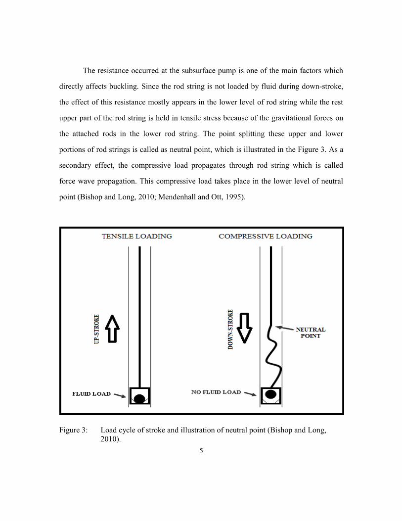
The resistance occurred at the subsurface pump is one of the main factors which
directly affects buckling. Since the rod string is not loaded by fluid during down-stroke,
the effect of this resistance mostly appears in the lower level of rod string while the rest
upper part of the rod string is held in tensile stress because of the gravitational forces on
the attached rods in the lower rod string. The point splitting these upper and lower
portions of rod strings is called as neutral point, which is illustrated in the Figure 3. As a
secondary effect, the compressive load propagates through rod string which is called
force wave propagation. This compressive load takes place in the lower level of neutral
point (Bishop and Long, 2010; Mendenhall and Ott, 1995).
Figure 3: Load cycle of stroke and illustration of neutral point (Bishop and Long,
2010).

6
To conclude, it is necessary to estimate the compressive force in order to achieve
a useful rod buckling analysis. Defining and analyzing rod buckling require better
understanding of neutral point because the principle of preventing buckling is related to
the methods to keep the neutral point at the lowest level of rod string.
2.2 ANALYSIS OF SUCKER ROD LOADS
Prior to estimating the compressive force, it is essential to analyze the forces
acting on rod string. Since the working principle of the sucker rod pumps is based on
reciprocating in the well, load on the sucker rods are fluctuating. Let us consider that
pump plunger begins moving up from the lowest level which it can reach in the pump
barrel. As pump moves up, travelling valve tends to close, and fluid begins being lifted
by pump plunger. Summation of fluid weight, buoyed rod weight and dynamic loads
gives the total load during the upstroke. Therefore, the maximum (peak) load occurs
during upstroke which is shown in the Textbook of Bommer and Podio as given in
Equation (2.1).
𝑊𝑚𝑎𝑥 = 𝑊𝑟𝑓 + 𝐹𝑜 + 𝑊𝐷𝑢𝑝…………………………………………..……………..…(2.1)
where Wmax is the maximum rod load during the upstroke, Wrf is the buoyed weight of
rod, Fo is the weight of fluid, and WDup is the dynamic load during the upstroke.
When the pump plunger begins moving down in the barrel, standing valve closes,
and increase in pressure occurs in the barrel. At some point of early time of downstroke,
pressure in the barrel reaches a critical value which opens the travelling valve, and fluid
load is transferred to the standing valve. Since fluid weight is hold by the standing valve,
and the direction of the dynamic load changes due to the downward motion of the rod
string, the minimum load supported by the sucker rods is shown as in Equation (2.2).

7
𝑊𝑚𝑖𝑛 = 𝑊𝑟𝑓 − 𝑊𝐷𝑑𝑜𝑤𝑛…………………………………………..…………….…..…(2.2)
where Wmin is the minimum rod load during the downstroke, and WDdown is the dynamic
loads during the downstroke.
Wrf can be calculated based on Archimedes’ Principle. According to Archimedes,
the buoyed weight of the rods is equal to the weight of the rods in air minus the weight of
the fluid displaced by the rod string. The displaced fluid weight and the buoyed rod
weight can be computed in Equation (2.3) and Equation (2.4), respectively.
𝑊𝐹𝐷 = 𝑊𝑟𝜌𝑓
𝜌𝑟= 𝑊𝑟
62.4𝛾𝑓
𝜌𝑟……………………………...……………..……………..…(2.3)
𝑊𝑟𝑓 = 𝑊𝑟 − 𝑊𝐹𝐷 = 𝑊𝑟 (1 −62.4𝛾𝑓
𝜌𝑟) ……………………………..………………..…(2.4)
where WFD is the weight of the fluid displaced by the rods, Wr is the weight of the rod in
air, ρf is the density of fluid, ρr is the density of rod, γf is the specific gravity of fluid
referenced to fresh water.
The weight of the fluid, which is lifted by the travelling valve during upstroke and
the standing valve during downstroke, can be estimated by multiplying the static pressure
of the produced fluid on the pump plunger by the cross-sectional area of the plunger.
Equation (2.5) gives the fluid load acting over the plunger.
𝐹𝑜 =62.4
144
𝑔𝑐
𝑔𝛾𝑓𝐿𝑛𝐴𝑝 = 0.34𝛾𝑓𝐿𝑛𝐷𝑝
2……………..…………………..……………..…(2.5)
where g is acceleration due to gravity, gc is gravitational conversion constant, Ln is net
fluid lift from the working fluid level, Ap is plunger area, and Dp is plunger diameter.
Since determining the dynamic forces acting on sucker rod pump will be
discussed in detail in the following sections, Equations (2.1) and (2.2) can be considered

8
as general expressions for the maximum and minimum loads. Dynamic forces basically
consist of the frictional and viscous forces inside the tubing string, such as the
mechanical pump friction, the friction between the rods and fluid, the fluid and tubing,
the tubing and rods, and the friction due to the fluid flowing through valves (Bommer and
Podio 2015).
2.3 CRITICAL BUCKLING LOADS
One of the questions whose answer is so valuable for the industry is how
compressive load causing rod buckling can be determined. According to Mendenhall and
Ott (1995), measuring, modeling, or empirically determining are the only ways to
determine the magnitude of the compressive load which depends on the specific rod
string installation. Although the most accurate way of determining the load is considered
as measuring the loads as a function of time and position at the pump by downhole load
cell device (DHLC), it is not feasible enough to perform routine analysis because it is
both expensive and time consuming. However, modeling, which is the most popular
alternative, needs to be calibrated by DHLC measurements. Therefore, well-calibrated
software can be utilized effectively for routine field works. The third method, empirically
determining, is less expensive and time consuming than the other two methods, but it is
not recommended because the complex dynamics of rod string is disregarded.
Leonhard Euler was the first mathematician investigating buckling and critical
load required to buckle an ideal, elastic slender column. In his investigation, it is assumed
that an ideal slender column is perfectly straight and compressed by load acting through
the centroid of the cross section. According to Euler’s study, this compression can be
described by one of three forms of equilibrium; stable, neutral, and unstable.

9
In stable equilibrium, the force not exceeding critical load is applied, and the
perfect straight shape of column does not alter. Under these conditions a small lateral
force will bend the column which will return to its straight form if the lateral force is
removed. If the applied force reaches to the critical force, a lateral force will produce a
deflection, and will not disappear when the lateral force is removed. This equilibrium
shapes neutral buckling. Equal to or greater loads than the critical load cause instability in
column which is called unstable buckling (Long and Bennett, 1996).
Euler solved the differential equation for the rod deflection curve with the free-
fixed boundary conditions assuming that the one end of the column is fixed while the
other one is free to move radially. The best condition describing the physical shape of the
bottom rod is free-fixed condition. The general expression for the critical load defined by
Euler is represented in Equation (2.6):
𝐹𝐶𝑅 = (𝜋2𝐸 𝐼)/(4𝐿2) ,……..…………….….……………………………………..…( 2.6)
where E is modulus of elasticity, I is moment of inertia, L is the length of column. The
moment of inertia for a circle can be expressed as a function of the diameter of circle in
Equation (2.7):
𝐼 = (𝜋𝐷4)/64 ,………………………………………………………………..………(2.7)
According to Long and Bennett, it is possible to develop Equation (2.6) based on
the end configuration of the column. Figure 4 illustrates these configurations whose
critical loads are as follows:
𝐹𝐶𝑅(𝑓𝑖𝑥𝑒𝑑) = (4 𝜋2𝐸 𝐼)/(𝐿2),……………..………………………………….………..(2.8)

10
𝐹𝐶𝑅(ℎ𝑖𝑛𝑔𝑒𝑑) = (𝜋2𝐸 𝐼)/(𝐿2),………………....…………...…………………………...(2.9)
where FCR(fixed) is the critical load for the fixed end configuration, FCR(hinged) is the critical
load for the hinged end configuration.
Figure 4: Configurations of fixed end and hinged end. (A) and (B) respectively
illustrate fixed end and hinged end configurations (Long et al., 1996).
The Equations above also reveal that the critical load of a fixed-end configuration
is four times greater than the critical load of a hinged-end configuration which can be
11
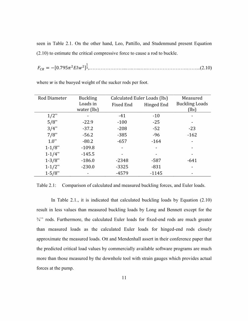
seen in Table 2.1. On the other hand, Leo, Pattillo, and Studenmund present Equation
(2.10) to estimate the critical compressive force to cause a rod to buckle.
𝐹𝐶𝑅 = −[0.795𝜋2𝐸𝐼𝑤2]1
3,…………………..….…...….…………………….……...(2.10)
where w is the buoyed weight of the sucker rods per foot.
Rod Diameter Buckling Loads in
water (lbf)
Calculated Euler Loads (lbf) Measured Buckling Loads
(lbf) Fixed End Hinged End
1/2'' - -41 -10 -
5/8'' -22.9 -100 -25 -
3/4'' -37.2 -208 -52 -23
7/8'' -56.2 -385 -96 -162
1.0'' -80.2 -657 -164 -
1-1/8'' -109.8 - - -
1-1/4'' -145.5 - - -
1-3/8'' -186.0 -2348 -587 -641
1-1/2'' -230.0 -3325 -831 -
1-5/8'' - -4579 -1145 -
Table 2.1: Comparison of calculated and measured buckling forces, and Euler loads.
In Table 2.1., it is indicated that calculated buckling loads by Equation (2.10)
result in less values than measured buckling loads by Long and Bennett except for the
¾’’ rods. Furthermore, the calculated Euler loads for fixed-end rods are much greater
than measured loads as the calculated Euler loads for hinged-end rods closely
approximate the measured loads. Ott and Mendenhall assert in their conference paper that
the predicted critical load values by commercially available software programs are much
more than those measured by the downhole tool with strain gauges which provides actual
forces at the pump.

12
2.4 BUCKLING TYPES
2.4.1 Sinusoidal Buckling
Euler’s critical load equation describes sinusoidal buckling which takes form of
sine wave. Also, Equation (2.11) is an expression for any other sinusoidal shape assumed
by the rod.
𝐹𝐶𝑆 = [(2𝑛 − 1)𝜋/(2 𝐿)] 2𝐸 𝐼 ,……………………………..……………………….(2.11)
where FCS is the critical load for sinusoidal buckling, and n is the number of full sine
waves in rod section.
Euler’s equation for the rod with free-fixed conditions is applicable to a finite
length rod; however, Equation (2.12) developed by Dawson and Paslay applies to an
infinite rod in an inclined borehole by assuming same boundary conditions (Mendenhall
and Ott, 1995).
𝐹𝐶𝑆 = 𝐸 𝐼 (𝑛′ π/L)2 + {𝑤 sin(𝑎) /𝑟}{𝐿/(𝑛′ π)}2 ,………..………………………..(2.12)
In Equation (2.12), a is the borehole inclination from vertical, and n’ represents the
number of half sine waves in the buckled rod section, and can be expressed as follows:
𝑛′ = 𝐿/𝑙𝑤,……………………………………………………………………………(2.13)
𝑙𝑤 = 𝜋 (𝐸 𝐼 / 𝑘)1/4,………………………………………………………………….(2.14)
𝑘 = 𝑤 sin(𝑎) /𝑟,…………………………………………………………………….(2.15)
where lw is the length of half-wave for rod string, k is elastic foundation constant, and r is
radial clearance between rod diameter and tubing wall.
13
2.4.2 Helical Buckling
The force required for transition of sinusoidal buckling to helical buckling is
negligible, so it is commonly assumed that rods buckle helically (Mendenhall and Ott,
1995). The minimum load buckling the rod into a helix is given as
𝐹𝐶𝐻 = (8 𝐸 𝐼 𝑤 𝑠𝑖𝑛(𝑎)/𝑟) 1/2,……………..………………………………………..(2.16)
Dawson and Paslay discuss the two experimental solutions to critical helical
buckling force presented by Dellinger et al. in 1983, and Lubinski and Woods in 1953.
Dellinger’s equation, Equation (2.17), gives results close to Equation (2.16) in the range
of fairly high stability as its results increase to 50% higher than Equation (2.16) in the
range of lower stability.
𝐹𝐶𝐻 = 2.93 (𝐸 𝐼)0.479 𝑤0.522 (𝑠𝑖𝑛(𝑎)/𝑟)0.436,……………………………..……….(2.17)
The experiential equation of Lubinski and Woods, Equation (2.18), also verifies
the theoretical solution (Mendenhall and Ott, 1995).
𝐹𝐶𝐻 = 2.85(𝐸 𝐼)0.504 𝑤0.496 (𝑠𝑖𝑛(𝑎)/𝑟)0.511,………………………..……………. (2.18)
The difference between these two equations is most probably caused by the fact
that Woods and Lubinski used the data directly while Dellinger et al., reconstructed the
experimental data to fit the equation (Dawson and Paslay, 1984).
2.5 HYDRAULICS OF SUCKER ROD PUMP
The hydraulics of the sucker rod pumps generally trigger major problems in
pumping system, such as partial pump fillage, gas interference, fluid pound, and
compressive loads on the valve rod. However, these effects are integrated into pump
14
friction constants in rod string design software because of lack of sufficient models.
These frictions can be examined in three categories; resistance against the downward
motion of the pump plunger due to resisting fluid flow through the inside of the plunger,
mechanical frictions caused by metal to metal sliding, and fluid resistance between the
plunger and the barrel (Cutler and Mansure, 1999). Therefore, Cutler and Mansure
discussed dynamic and geometric details to estimate the frictional losses in the model
which was developed by Sandia National Laboratories, and their effects on the
calculations.
The first investigated issue in their study is pressure drop across valves which has
critical effect on pump filling, gas leakage, and compression loading of the valve rod. By
testing various sizes of balls and seats in the valves with open and closed cages, they
conclude that using a smaller ball and larger seat ID decreases the pressure losses in both
closed and open cage designs, and that using the high efficient valves adequately
improves the performance of the valves compared to the less efficient valves. As pressure
drop across entire pump is investigated, the pressure loss in the travelling valve is,
unsurprisingly, found more than in the standing valve because the area allowing fluid
flow in the travelling valve is comparatively smaller than in the standing valve.
According to Cutler and Mansure; however, losing more pressure in the pump exit than
in the travelling valve was not an expected situation, and can be seen as an opportunity to
improve the pump design.
As most parameters in downhole are full of uncertainties, the uncertainty of fluid
viscosity in downhole and the effect of viscosity have always been extensive study area
to researchers. Cutler and Mansure notice that at low to medium flow rates changing the
viscosity from 0.1 cP to 100 cP has very little effect on pressure losses calculated in the

15
model. While this effect becomes greater at high flow rate, it still stays in a small range
of change. Although it was stated that only a few experiments investigating the effect of
the viscosity had been conducted in that study, replacing the water at 1 cP with Weeks
Island Crude at 15 cP only increased the pressure loss by 6%.
Other issues investigated by Cutler and Mansure are effects of surface roughness,
valve design, and ball chatter. First of all, according to the results of their model, surface
roughness has little effect if the absolute roughness does not exceed 1000 microinches.
For the roughness values greater than that limit, pressure loss increases significantly.
Secondly, in 1984 Allen and Svinos asserted that enlarging the I.D. of the valve
seat, using open cages rather than closed cages, and increasing I.D. of the pump plunger
reduced the resisting forces during downstroke. As the results obtained from the model
by Cutler and Mansure are consistent with this study, it also emphasizes the connection
between reducing the changes in flow area and the decrease in the resisting forces.
Therefore, for an accurate prediction of pressure drop along with pump, the fine details of
the components in the pump should be included in models, and the significant effects of
these details in pressure drop should be considered when designing new pump
components.
Thirdly, the effect of ball chatter was tested by Cutler and Mansure for various
combinations, such as cases with the ball and seat, with just the seat, and without the ball
or the seat. The results show that pressure drop rises up rapidly at low flow rates and
decreases after reaching a critical flow rate. This flow rate can be defined as a critical
level at which the ball stops chattering. It can be concluded that the size of the check
valves should be determined to prevent the valve from partially opening. The partially
opened valve is one of the factors increasing the pressure losses significantly.

16
To sum up, developing a model for analyzing flow in sucker rod pumps provides
better understanding of hydraulics of pumps. The effects of the variable parameters, such
as viscosity, valve design, and surface roughness can be analyzed to more accurately
predict pressure drops and to reveal the reasons causing the rod buckling.
2.6 COMPRESSIVE FORCES ACTING ON THE BOTTOM OF THE SUCKER ROD
In the previous sections, sucker rod loads were analyzed, and the maximum and
minimum loads were expressed in Equation (2.1) and Equation (2.2), respectively. To
analyze the tendency of the sucker rod to buckle, more detailed expression is required for
the dynamic force acting near the bottom of the rod string. This section will discuss the
dynamic forces caused by fluid friction (drag) and mechanical friction in the annulus
between the pump plunger and barrel. During upstroke, these forces cannot result in
buckling because the forces are tensional, but same forces result in compressive effect on
the bottom of sucker rod during downstroke since these dynamic forces act opposite to
the sucker rod motion.
Some of the load analyses in the literature ignore the friction force in the
travelling valve due to the pressure differences in the pump plunger (Lea et al., 1995).
However, tests and model calculations show that pressure difference is required to move
the fluid through travelling valve (Cutler and Mansure, 1999). Therefore, this force
during downstroke is equal to the cross-sectional area of the plunger times the pressure
difference between the ends of the pump plunger as shown in Equation (2.19).
𝐹𝑇𝑉 = (𝑃𝑏 − 𝑃𝑎)𝐴𝑝 = −𝜋𝐷𝑝2∆𝑃/4,………………………………..……………….(2.19)
where Pb is the pressure below the pump plunger, Pa is the pressure above the pump
plunger, and ΔP is the pressure difference across the plunger.
17
To include the viscous fluid drag between the sides of the plunger and the barrel,
Lea and Nickens use the following formula:
𝐹𝑑 = −𝜋𝑅𝑖𝐿𝑝𝜕𝑃
𝜕𝑧𝐶𝑅 − 2.088 × 10⁻⁵ 2𝜋𝑅𝑖𝐿𝑝𝜇
𝐶𝑅𝑉𝑝,…………...………………..……....(2.20)
where Ri is the radius of the wall corresponding to inner wall of the plunger/barrel gap, Lp
is plunger length, ∂P/∂z is the pressure gradient of fluid, CR is radial clearance, µ is fluid
viscosity, and Vp is plunger velocity.
After the force due to the pressure difference through travelling valve is added to
Equation (2.20), the compressive buckling force, Fc, is as follows:
𝐹𝑐 = −𝜋𝐷𝑝2∆𝑃/4 − 𝜋𝑅𝑖
(𝐷𝑏−𝐷𝑝)
2∆𝑃 − 1.312 × 10⁻⁴ 𝐷𝑝𝐿𝑝𝜇
(𝐷𝑏−𝐷𝑝)𝑉𝑝,……………..……(2.21)
where Db is the diameter of pump barrel.
πRi(Db-Dp)/2 can be replaced by π(Db2-Dp2)/8 because the πRi(Db-Dp)/2 product
approximates the one half the area of the annulus in the parallel plate. Then, Equation
(2.21) reduces to Equation (2.22).
𝐹𝑐 = −𝜋(𝐷𝑏
2+𝐷𝑝2)
8∆𝑃 − 1.312 × 10⁻⁴ 𝐷𝑝𝐿𝑝𝜇
(𝐷𝑏−𝐷𝑝)𝑉𝑝,………………….………...……….(2.22)
Equation (2.22) has two terms which are directly proportional to the pressure
difference and the fluid velocity. Cutler and Mansure prefer using the pump discharge
rate rather than ∆P and Vp, so these terms are rearranged in the form of a function of the
rate. After testing pressure drop across the travelling valve and plunger with changing
flow rates, an empirical equation is created as follows:
∆𝑃 ≈ 𝐾 𝑄2, ………………………………...……………………………………….(2.23)

18
where the coefficient, K, is in psi/(bbl/day)2, pressure drop, ΔP, is in psi, and pump
discharge rate, Q, is in bbl/day.
To determine the maximum buckling rod, the peak velocity should be taken into
account in the calculation. However, if sinusoidal motion is assumed, the peak velocity
can be related to the average velocity as in Equation (2.24).
𝑉𝑎𝑣𝑒𝑟𝑎𝑔𝑒 =𝑉𝑝𝑒𝑎𝑘
2𝜋(∫ sin[𝜃]𝑑𝜃
𝜋
0+ ∫ 0𝑑𝜃
2𝜋
𝜋) =
𝑉𝑝𝑒𝑎𝑘
𝜋,…………………….………….(2.24)
where Vaverage is average velocity, Vpeak is peak velocity, and θ is the coordinate of
sinusoidal motion of surface pump.
Now, the peak plunger velocity can be rewritten as Vaverage is equal to Q/Ap.
𝑉𝑝|𝑝𝑒𝑎𝑘
= 𝜋𝑄
𝐴𝑝=
𝑄
26.7 𝐷𝑝2
𝑓𝑡 𝑖𝑛2𝑑𝑎𝑦
sec 𝑏𝑏𝑙,……………………………………………………(2.25)
where the peak plunger velocity is ft/sec, the pump discharge rate is in bbl/day, and the
plunger diameter is in inches. The substitution of Equation (2.23) and (2.25) into
Equation (2.22) gives the final form of the buckling force due to pressure and plunger
velocity effects.
𝐹𝑐 ≈ −𝜋(𝐷𝑏
2+𝐷𝑝2)
8𝐾𝑄2 − 1.312 × 10⁻⁴ 𝐷𝑝𝐿𝑝𝜇
(𝐷𝑏−𝐷𝑝)
𝑄
26.7 𝐷𝑝2,…………………...….……....(2.26)
A slightly modified form of this equation is provided in the Beam Lift Handbook
by including -Fm for the mechanical (Coulomb) friction between plunger and barrel in
addition to Equation (2.27).
𝐹𝑐 = −𝜋(𝐷𝑏
2+𝐷𝑝2)
8∆𝑃 − 4.906 × 10⁻⁶ 𝐿𝑝𝜇𝑄
(𝐷𝑏−𝐷𝑝)𝐷𝑝− 𝐹𝑚,…….……………...………....(2.27)

19
Contrary to the experimental approach of Cutler and Mansure to the pressure drop
through travelling valve, Bommer and Podio present Equation (2.28) to estimate the
pressure loss by using Bernoulli’s equation to account for changes in elevation, flow
velocity, and irreversible frictional losses.
∆𝑃 = 2𝑣2 𝐿𝑝
𝐷𝑇𝑉/12𝑓
𝜌𝑓
𝑔𝑐(144)+
1
2𝑣2𝑒𝑣
𝜌𝑓
𝑔𝑐(144)+ 0.433𝛾𝑓𝐿𝑝,.…...…………………..….(2.28)
where v is maximum fluid velocity through plunger, Lp is the overall plunger length, DTV
is the travelling valve seat diameter, f is the Fanning friction factor, ρf is the fluid density,
gc is the mass to force conversion, γf is the liquid specific gravity, and ev is the entrance
and exit friction factor which is represented by Equation (2.29).
𝑒𝑣 = 0.45(1 − 𝛽) + (1
𝛽− 1)
2
,.…………………………………………………..….(2.29)
where β is the ratio of travelling valve diameter to barrel diameter that can be calculated
by using Equation (2.30).
𝛽 =𝐷𝑇𝑉
𝐷𝑏⁄ ,.…………………….………………………………………………..….(2.30)
Cutler and Mansure (1999) also developed a model to predict the pressure drop
due to flow through the pump. The five steps of this well-explained model in the
Appendix of their paper are dividing the pump into logical nodes at each change in
geometry, determining Reynolds number at each node for each flow rate, determining the
Friction Factor at each node for each flow rate by solving iteratively, finding the
irreversible fluid friction losses between each node by considering sudden or gradual
contraction and enlargement in the pump, and finally determining the total pressure loss
between each set of nodes.
20
2.7 PREVENTING BUCKLING
The determination of the compressive force is necessary to compare with the
critical buckling force. If the maximum value of compressive force exceeds the critical
buckling load, whether the shape of buckling is sinusoidal or helical should be defined.
Based on the buckling shape, the possibility of fatigue can be evaluated by estimating the
stresses on the rod string, and it can be concluded whether or not the compressive loads
are acceptable. In such situation that the compressive loads are unacceptable, surface
pumping parameters should be initially investigated because some minor changes in
surface pumping parameters, such as slowing pumping speed or reducing stroke length
can reduce the rod buckling effect. Also, these changes can usually provide a better
solution in a financial point of view and can be more cost effective than changing down-
hole parameters. However, changing the surface pumping parameters is only practical if
it can be accomplished without significant reductions in oil and gas productions (Bishop
and Long, 2010).
If these changes do not resolve the rod buckling problem, other alternatives, using
a larger clearance, shorter barrel, larger TV, redesigning the rod string, or adding sinker
bars should be taken into account to try to avoid possible buckling (Lea et al., 1995,
Bommer and Podio 2015).

21
Chapter 3: Using Sinker Bar to Prevent Buckling
This chapter focuses on using sinker bar to prevent buckling and its effects on
compressive force at the top of the pump plunger. The purpose of this common method is
to replace the lower part of rod string with heavy weight sinker bars to increase the
rigidity of rod string (Bishop and Long, 2010). In Equation (2.7), the moment of inertia
for a circle is proportional to its diameter. Therefore, larger diameter of same material
tends to have higher moment of inertia. In other words, increasing the diameter and
weight of rods drastically heightens the critical buckling load as the relation can be seen
in Equations (2.6) and (2.7). Furthermore, sinker bars can reduce the length of the rods
affected by compressive force since their weight drives the dynamic neutral point closer
to the pump plunger. Because, in general, it is difficult to model short sections of heavy
weight sinker bar, a well-calibrated software program should be utilized for modeling the
dynamics of the rod string to insure whether there have been inappreciable changes in the
system, or not (Mendenhall and Ott, 1995).
Sinker bars can be considered as sucker rods with larger diameter which help
keep the rod string straight and in tension by providing concentrated weight above the
pump. Table 3.1 shows the difference between the weights of sinker bars and sucker rods.
It can be seen that the weights of sinker bars are quite greater than those of sucker rods
which are indeed proportional to their cross-sectional areas. Since this extra weight due to
replacing the sucker rod with sinker bars can overcome the compressive load acting at the
bottom of the string, sinker bars are commonly used to prevent buckling in the sucker rod
pumps.
The general idea of using sinker bars is to move the neutral point downward to the
closest possible point to pump plunger. As it is discussed in Section 2.1, the neutral point
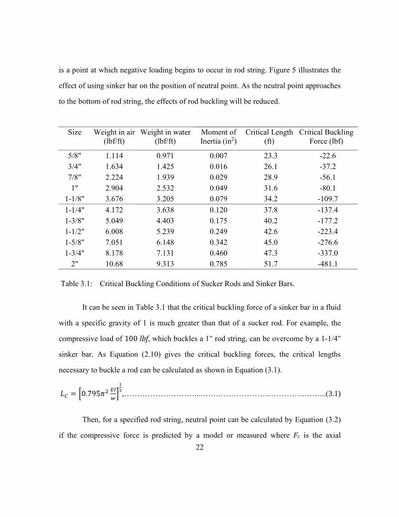
22
is a point at which negative loading begins to occur in rod string. Figure 5 illustrates the
effect of using sinker bar on the position of neutral point. As the neutral point approaches
to the bottom of rod string, the effects of rod buckling will be reduced.
Table 3.1: Critical Buckling Conditions of Sucker Rods and Sinker Bars.
It can be seen in Table 3.1 that the critical buckling force of a sinker bar in a fluid
with a specific gravity of 1 is much greater than that of a sucker rod. For example, the
compressive load of 100 lbf, which buckles a 1" rod string, can be overcome by a 1-1/4"
sinker bar. As Equation (2.10) gives the critical buckling forces, the critical lengths
necessary to buckle a rod can be calculated as shown in Equation (3.1).
𝐿𝐶 = [0.795𝜋2 𝐸𝐼
𝑤]
1
3,………………………...…….………………...………….……...(3.1)
Then, for a specified rod string, neutral point can be calculated by Equation (3.2)
if the compressive force is predicted by a model or measured where Fc is the axial
Size Weight in air
(lbf/ft)
Weight in water
(lbf/ft)
Moment of
Inertia (in2)
Critical Length
(ft)
Critical Buckling
Force (lbf)
5/8" 1.114 0.971 0.007 23.3 -22.6
3/4" 1.634 1.425 0.016 26.1 -37.2
7/8" 2.224 1.939 0.029 28.9 -56.1
1" 2.904 2.532 0.049 31.6 -80.1
1-1/8" 3.676 3.205 0.079 34.2 -109.7
1-1/4" 4.172 3.638 0.120 37.8 -137.4
1-3/8" 5.049 4.403 0.175 40.2 -177.2
1-1/2" 6.008 5.239 0.249 42.6 -223.4
1-5/8" 7.051 6.148 0.342 45.0 -276.6
1-3/4" 8.178 7.131 0.460 47.3 -337.0
2" 10.68 9.313 0.785 51.7 -481.1

23
compressive force. Comparing the critical length of this specified rod and the neutral
point leads to discover if the rod will be buckled under the compressive force. Applying
to the same example given above, the neutral point of the 1" rod string is calculated as
39.5 feet above the bottom of rod string with the assumption of a compressive force of
100 lbf. The critical length of 1" sucker rod is estimated as 31.6 feet in Table 3.1, and it is
less than the neutral point; therefore, the lower steel rods are predicted to buckle.
𝐿𝑁𝑃 =|𝐹𝐶𝑅|
𝑤𝑅(1−0.127𝛾𝑓),……………..……………………………….………….………...(3.2)
Figure 5: The position change of neutral point with using sinker bar section (Bishop
and Long, 2010).

24
If using sinker bar is considered as the method to prevent buckling in this
situation, the length of an alternative sinker bars can be estimated by Equation (3.3). This
equation is based on the difference between the compressive force and the critical force
necessary to buckle the rod above the sinker bar. On the other hand, Lea et al. (1995)
provide a similar equation to calculate the length of the sinker bar. Because it is based on
only compressive force, Equation (3.4) provided by Lea and others overestimates the
necessary length of the sinker bar.
𝐿𝑆𝐵 =|𝐹𝑐−𝐹𝐶𝑅|
𝑤𝑆𝐵(1−0.127𝛾𝑓),…………………………..…………………………….………...(3.3)
𝐿𝑆𝐵 =|𝐹𝑐|
𝑤𝑆𝐵(1−0.127𝛾𝑓),…………………………..…………………………….………...(3.4)
If we go back to the previous example, the length of 1-1/4" sinker bars which 1"
sucker rods is replaced with is estimated as 5.5 feet by Equation (3.3) while Equation
(3.4) gives a value of 27.2 feet for the length of the sinker bars. The reason of these
different results is that the length calculated by Equation (3.3) targets to lower the
compressive force acting at the bottom of 1" rod taper to its critical buckling force, -80.1
lbf.; however, Equation (3.4) completely cancels out this compressive load.
In theory, these two values do not seem making a difference, but the effects of
using longer sinker bars due to the additional viscous force in annulus between sinker
bars and tubing is open to further investigations and experiments. This additional viscous
force increases the rod load during up-stroke, and decreases it during down-stroke,
therefore; the length of the sinker bars directly has an impact on the rod life. It may even
cause buckling in sinker bars because of increasing compression. On the other hand, the
effects of sinker bar diameter on tubing failures are studied by Bishop and Long (2010).

25
In their paper, it is stated that utilizing the largest diameter sinker bar for the available
internal diameter of the tubing resulted in reduced tubing wall loss. Therefore,
minimizing the length of sinker bar is as significant as maximizing the rod diameter
which increases the contact area between tubing and rod, and reduces the concentrated
wear on tubing wall. However, it must be also investigated if decreased flow area in
annulus increases the drag forces, so compressive forces acting on the bottom of the rod
string.

26
Chapter 4: Conclusions
As low oil price has been a great concern in the petroleum industry for the last
two years, rod buckling can easily result in the excessive well expenses by causing tubing
wear, fatigue failures, and decreased rod life. There are many studies in the literature
which investigate the compressive forces causing rod buckling and solutions to prevent
rod buckling.
In this report, it is concluded that using sinker bars to increase the rigidity of rod
string is the most practiced method in the industry. It has been shown that sinker bars
reduced the effect of buckling if changing surface parameters, such as pumping velocity
and stroke length was not practical which would be less expensive and time consuming.
However, determining the true compressive forces has a key role to adjust the length of
sinker bar. Several commercial software have been developed by the industry to estimate
the compressive force; however, they should be calibrated with field data and downhole
measurements to be able to represent each specified oil well.
On the other hand, there are issues about using sinker bars because viscous force
between tubing and sinker bar can cause additional compressive force that can be a topic
for further research. These viscous loads need an extensive study since it has been
asserted in the literature that using the largest available sinker bar diameters reduced
tubing wear and failures significantly.
27
Glossary
a: borehole inclination from vertical [degrees]
Ap: plunger area [inches2]
CR: radial clearance [inches]
D: diameter of column [inches]
Db: barrel diameter [inches]
Dp: plunger diameter [inches]
DTV: travelling valve seat diameter [inches]
ev: entrance and exit friction factor [-]
E: modulus of elasticity [30.5x10⁶ psi for steel]
f: Fanning friction factor [-]
Fc: total buckling force [lbf]
FCH: critical load for helical buckling [lbf]
FCR: critical load [lbf]
FCR(fixed): critical load for the fixed end configuration [lbf]
FCR(hinged): critical load for the hinged end configuration [lbf]
FCS: critical load for sinusoidal buckling [lbf]
Fd: drag force [lbf]
Fo: fluid weight [lbf]
FTV: frictional force due to fluid flowing through travelling valve [lbf]
g: acceleration due to gravity [ft/sec2]
gc: gravitational conversion constant, [32.174 lbm.ft/(lbf.sec2)]
I: moment of inertia [inches4]
28
k: elastic foundation constant [psi]
K: empirical pressure coefficient [psi/(bbl/day)2]
lw: length of half-wave for rod string [inches]
L: length of column [inches]
Lc: critical length [ft]
Ln: net fluid lift from the working fluid level [ft]
LNP: neutral point [ft]
Lp: plunger length [ft]
LSB: total length of sinker bars [ft]
n: number of full sine waves in rod section [-]
n’: number of half sine waves in rod section [-]
Pa: pressure above the pump plunger [psi]
Pb: pressure below the pump plunger [psi]
r: radial clearance between rod diameter and tubing wall [inches]
Ri: radius of the wall corresponding to inner wall of the plunger/barrel gap [inches]
Q: pump discharge rate [bbl/day]
v: maximum fluid velocity through plunger [ft/sec]
Vaverage: average velocity [ft/sec]
Vp: plunger velocity [ft/sec]
Vpeak: peak velocity [ft/sec]
w: buoyed weight per ft. of the sucker rods [lbf/ft]
wSB: air weight per ft. of the sinker bars [lbf/ft]
wR: air weight per ft. of the sucker rods [lbf/ft]
WDdown: dynamic loads during the downstroke [lbf]

29
WDup: dynamic load during the upstroke [lbf]
WFD: weight of the fluid displaced by the rods [lbf]
Wmax: maximum rod load during the upstroke [lbf]
Wmin: minimum rod load during the downstroke [lbf]
Wr: rod weight in air [lbf]
Wrf: buoyed rod weight [lbf]
β: ratio of TV diameter to barrel diameter [-]
ΔP: pressure difference across the plunger [psi]
γf: specific gravity of the fluid referenced to fresh water [-]
µ: fluid viscosity [cP]
∂P/∂z: pressure gradient of fluid [psi/ft]
ρf: density of the fluid [lbm/ft3]
ρr: density of the rod [lbm/ft3]
θ: coordinate of sinusoidal motion of surface pump [degree]

30
References
A. Lubinski and H. B. Woods, “Factors Affecting the Angle of Inclined and Doglegging
in Rotary Bore Holes,” API Drilling and Production Practice, 1953, pp 222-250.
A. Lubinski, W. S. Althouse and J. L. Logan, “Helical Buckling of Tubing Sealed in
Packers,” Journal of Petroleum Technology, June 1962.
D. Bishop and S. W. Long, “Minimize Rod Buckling to Reduce Tubing Failure,”
Southwestern Petroleum Short Course Association, 2010.
G. L. Mendenhall and R. E. Ott, “Solving Rod Buckling,” Southwestern Petroleum Short
Course Association, April 1995.
J. F. Lea and H. V. Nickens, “Beam Lift Issues, Appendix,” Southwestern Petroleum
Short Course Association, 1998.
J. F. Lea, P. D. Pattillo, and W. R. Studenmund, “Interpretation of Calculated Forces on
Sucker Rods,” SPE Production and Facilities, February 1995.
L. F. Allen and J. G. Svinos, “Rod Pumping Optimization Program Reduces Equipment
Failures and Operating Costs,” SPE-13247, September 1984.
P. M. Bommer and A. L. Podio, The Beam Lift Handbook 1st Edition, Revised, The
University of Texas at Austin Petroleum Extension, 2015.

31
R. Dawson and P. R. Paslay, “Drillpipe Buckling in Inclined Holes,” Journal of
Petroleum Technology, October 1984.
R. P. Cutler and A. J. Mansure, “Fluid Dynamics in Sucker Rod Pumps,” Sandia National
Laboratories Report SAND99-0093C, May 1999.
S. W. Long and D. W. Bennett, “Euler Loads and Measured Sucker Rod/Sinkerbar
Buckling,” SPE 35214, March 1996.
T. B. Dellinger, W. Gravley, and J. E. Walraven, “Preventing Buckling in Drill Strength,”
U.S. Patent No 4384483 A, May 1983.


![Media ppt cagdas[1]](https://static.fdocuments.us/doc/165x107/554ecb87b4c905de468b5138/media-ppt-cagdas1.jpg)

