Copyright by Alan Renison Kreisa 2008
127
Copyright by Alan Renison Kreisa 2008
Transcript of Copyright by Alan Renison Kreisa 2008

Copyright
by
Alan Renison Kreisa
2008

Constructibility of Prestressed Concrete Panels for Use at Skewed
Expansion Joints
by
Alan Rension Kreisa, B.S.
Thesis
Presented to the Faculty of the Graduate School of
The University of Texas at Austin
in Partial Fulfillment
of the Requirements
for the Degree of
Master of Science in Engineering
The University of Texas at Austin
May 2008

Constructibility of Prestressed Concrete Panels for Use at Skewed
Expansion Joints
Approved by Supervising Committee:
James O. Jirsa, Supervisor
Oguzhan Bayrak

iv
Acknowledgements
I would like to thank the Texas Department of Transportation for funding this
research project which allowed me to attend graduate school. My education from The
University of Texas at Austin will no doubt benefit me throughout my career.
I would like to thank Andrew Valentine, Blake Stasney, Dennis Fillip, and Greg
Harris for their assistance during this research project. I would also like to thank my
classmates that have assisted during the concrete batching and casting processes.
Finally, I would like to thank Dr. Bayrak, Dr. Jirsa, and Dr. Wood for their
guidance over the course of this research project.
May 2, 2008

v
Abstract
Constructibility of Prestressed Concrete Panels for Use at Skewed
Expansion Joints
Alan Renison Kreisa, M.S.E.
The University of Texas at Austin, 2008
Supervisor: James O. Jirsa
The Texas Department of Transportation (TxDOT) has typically used a thickened,
cast-in-place slab in lieu of any special supports or diaphragms at concrete bridge deck
expansion joints for many years. A new detail to replace the thickened cast-in-place slab
was developed was developed under TxDOT research project 0-44118. The standard
prestressed panels typically used at interior portions of the bridge are continued to the
expansion joints in zero degree skew bridge decks. The new detail improved
construction speed, safety, and economy.
The primary goals of the research project reported here were to evaluate the
feasibility of producing trapezoidal-shaped prestressed concrete panels as well as address
construction related issues so that use of the new panel detail can be extended to include
skewed expansion joints. A total of eight trapezoidal panels were fabricated using two

vi
different prestressing layouts and various geometries. In two panels, a flared prestressing
strand pattern was used while in the other six panels, an arrangement with the
prestressing strands parallel to the skewed end of the panel was used. A 45 degree skew
angle was used in four of the panels and a 30 degree skew angle was used in the other
four panels. A short edge length of 45 in. or 60 in. was used for the trapezoidal panels
and all panels were 4 in. thick and 9 ft. 6 in. wide.
The results of the research project demonstrate that producing trapezoidal
prestressed panels can be economical while accommodating a wide range of geometries.
The research project showed that trapezoidal prestressed panels provide a feasible
alternative to stay-in-place formwork at skewed expansion joints.

vii
Table of Contents
CHAPTER 1 INTRODUCTION ...............................................................................1 1.1 Introduction ...............................................................................................1 1.2 Background ...............................................................................................1 1.3 Objectives and Scope ................................................................................6
CHAPTER 2 LITERATURE REVIEW .....................................................................7 2.1 Introduction ...............................................................................................7 2.2 Recent Tests of Expansion Joint Behavior ...............................................7
2.2.1 TxDOT Project 0-4418 .................................................................7 2.2.1.1 Ryan (2003) ......................................................................8 2.2.1.2 Griffith (2003) .................................................................12 2.2.1.3 Coselli (2004)..................................................................13
2.2.2 TxDOT Project 0-5367 ...............................................................15 2.2.2.1 Agnew (2007) .................................................................15
2.3 Skewed Prestressed Panels and Slabs .....................................................18 2.3.1 Abendroth, Pratanata, and Singh (1991) .....................................18
2.3.1.1 Experimental Testing of Trapezoidal Panels ..................18 2.3.1.2 Results from Panel Questionnaires .................................23
2.3.2 Rajagopalan (2006) .....................................................................27 2.4 Research Significance .............................................................................30
CHAPTER 3 DESIGN OF TEST SPECIMENS .......................................................31 3.1 Introduction .............................................................................................31 3.2 Preliminary Design .................................................................................31
3.2.1 Panel Geometry ...........................................................................32 3.2.2 Reinforcement Alternatives ........................................................35 3.2.3 Construction Issues .....................................................................37
3.2.3.1 Contractor Requests ........................................................37 3.2.3.2 Fabricator Capabilities ....................................................40 3.2.3.3 TxDOT Requirements .....................................................40

viii
3.2.4 Selected Designs .........................................................................43 3.3 Flared Prestressing Pattern ......................................................................46
3.3.1 Strand Layout ..............................................................................47 3.3.2 Additional Mild Reinforcement ..................................................48 3.3.3 Release Strength ..........................................................................50
3.4 Parallel Prestressing Pattern ....................................................................50 3.4.1 Panel and Strand Geometry ........................................................50 3.4.3 Additional Mild Reinforcement ..................................................51 3.4.4 Commercial Fabrication ..............................................................52
3.5 Design Summary .....................................................................................55 3.6 Concrete Mix Design ..............................................................................56
CHAPTER 4 PREFABRICATION ACTIVITIES .....................................................57 4.1 Introduction .............................................................................................57 4.2 Prestressing Frame ..................................................................................57
4.2.1 Base Reaction Frame ..................................................................59 4.2.2 Bulkheads ....................................................................................61 4.2.3 Anchoring ...................................................................................64
4.2.3.1 Flared Prestressing Pattern ..............................................64 4.2.3.2 Parallel Prestressing Pattern ............................................67
4.2.4 Modifications ..............................................................................68 4.3 Instrumentation .......................................................................................70 4.4 Prestressing Strand Tests ........................................................................71 4.5 Strand Stressing ......................................................................................72 4.6 Concrete Batching ...................................................................................74 4.8 Early Concrete Strength ..........................................................................74 4.9 Release ....................................................................................................75 4.10 Summary ...............................................................................................76
CHAPTER 5 CONSTRUCTION OF PRESTRESSED PANELS ...............................77 5.1 Introduction .............................................................................................77 5.2 45 Degree Skew Panels ...........................................................................77
ix
5.2.1 Stressing and Relaxation .............................................................77 5.2.2 Formwork and Rebar ..................................................................84 5.2.3 Casting ........................................................................................87 5.2.4 Release ........................................................................................90 5.2.5 Assessment of Panel Construction ..............................................91
5.3 30 Degree Skew Panels ...........................................................................93 5.3.1 Formwork and Rebar ..................................................................93 5.3.2 Casting ........................................................................................97 5.3.3 Assessment of Panel Construction ..............................................99
CHAPTER 6 BRIDGE DECK CONSTRUCTION .................................................100 6.1 Introduction ...........................................................................................100 6.2 Bridge Deck Specimens ........................................................................100 6.3 Bedding Strip Compression ..................................................................103
6.3.1 Specimen P45P1 .......................................................................103 6.3.2 Specimen P45P2 .......................................................................103 6.3.3 Specimen P45P3 .......................................................................105 6.3.4 Specimens P30P1 and P30P2....................................................106
6.4 Assessment of Construction of Bridge Deck Specimens ......................106
CHAPTER 7 SUMMARY, CONCLUSIONS, AND RECOMMENDATIONS ...........108 7.1 Summary ...............................................................................................108 7.2 Conclusions ...........................................................................................109 7.3 Recommendations .................................................................................111
REFERENCES .......................................................................................................113
VITA ....................................................................................................................114

x
List of Tables
Table 2.1: Selected survey results from design agencies (Abendroth 1991). .................. 24 Table 2.2: Selected survey results from manufacturing agencies (Abendroth 1991). ..... 26 Table 3.1: Bridge skew angles in Texas .......................................................................... 44 Table 3.2: Bearing pressure using TxDOT minimum 34" bearing length ....................... 46 Table 3.3: Minimum short edge bearing lengths for 40 psi and 60 psi bedding strips .... 46 Table 3.4: Summary of panel designs .............................................................................. 56 Table 3.5: Concrete mix design properties ...................................................................... 56 Table 5.1: Summary of concrete release and 28-day strengths ....................................... 91 Table 6.1: Summary of bridge deck test specimens ...................................................... 101

xi
List of Figures
Figure 1.1: Typical bridge construction prior to placing bridge deck (Agnew 2007) ....... 2 Figure 1.2: Typical bridge construction during placement of prestressed panels (Agnew 2007) ................................................................................................................................... 2 Figure 1.3: Panels and reinforcing steel prior to casting topping slab (Agnew 2007) ....... 3 Figure 1.4: Cross-section of IBTS detail (Agnew 2007) ................................................... 4 Figure 1.5: Temporary formwork erected for IBTS detail ................................................ 5 Figure 1.6: Complex geometry and hazardous work environment at an unfinished skewed expansion joint (Agnew 2007) ............................................................................... 5 Figure 2.1: TxDOT IBTS detail, plan view ....................................................................... 9 Figure 2.2: TxDOT IBTS detail, cross-sections from Figure 2.1 .................................... 10 Figure 2.3: Simple cross-section view of UTSE detail (Ryan 2003) ............................... 10 Figure 2.4: Plan view of zero degree skew bridge deck specimen (Ryan 2003) ............. 11 Figure 2.5: Plan view of 45 degree skew bridge deck (Griffith 2003) ............................ 13 Figure 2.6: Cross-section of prestressed concrete panel end detail (Coselli 2004) ......... 14 Figure 2.7: Plan view of zero degree skew bridge deck (Coselli 2004) .......................... 15 Figure 2.8: Plan view of positive moment fatigue test (Agnew 2007) ............................ 16 Figure 2.9: Elevation view of positive moment fatigue test (Agnew 2007) .................... 16 Figure 2.10: Plan view of negative moment fatigue test (Agnew 2007) ......................... 17 Figure 2.11: Elevation view of negative moment fatigue test (Agnew 2007) ................. 17 Figure 2.12: Plan view of 15 degree skew test (Abendroth 1991) ................................... 19 Figure 2.13: Plan view of 30 degree skew test (Abendroth 1991) ................................... 20 Figure 2.14: Plan view of 45 degree skew test (Abendroth 1991) ................................... 20 Figure 2.15: Cross-section of composite specimens (Abendroth 1991) .......................... 21 Figure 2.16: Trapezoidal prestressed concrete panels: (a) Plan view (b) Section A-A (c) Section B-B (Abendroth, et al. 1991) ............................................................................... 22 Figure 2.17: Principle stress trajectories for various skews (Rajagopalan 2006) ............ 28 Figure 2.18: (a) Deflection profile in a skewed deck (b) 'S' shaped deflection profile near the support line for large skew angles (Rajagopalan 2006) .............................................. 28 Figure 2.19: Fan-shaped post-tensioning cable layout (Rajagopalan 2006) ..................... 29 Figure 3.1: Option 1 - Single trapezoidal panels ............................................................. 32 Figure 3.2: Option 2 - Combination of two trapezoidal panels ....................................... 33 Figure 3.3: Option 3 – Combination of quadrilateral and trapezoidal panels .................. 34 Figure 3.4: Strands oriented perpendicular to the girders ................................................ 35 Figure 3.5: Strands oriented parallel to the skewed end .................................................. 36 Figure 3.6: Strands flared throughout panel .................................................................... 36 Figure 3.7: (a) Current construction techniques (b) Construction issue with end panels (c) Possible solution using two field-sawn panels .................................................................. 39 Figure 3.8: Prestressed concrete panel bearing details .................................................... 41 Figure 3.9: Prestressed concrete panel standard details ................................................... 42 Figure 3.10: Selected design alternatives ......................................................................... 43 Figure 3.11: Number of pretensioned I-girder bridges with given skew angles (Van Landuyt 2006) ................................................................................................................... 44 Figure 3.12: Number of all bridge types with given skew angle (Van Landuyt 2006) ... 45

xii
Figure 3.13: Strand spacing for flared strand pattern ...................................................... 48 Figure 3.14: Hairpin layout for flared strand pattern ....................................................... 49 Figure 3.15: Parallel strand panel designs ....................................................................... 51 Figure 3.16: Additional deformed bars in parallel strand panels ..................................... 52 Figure 3.17: 30 Degree skew panel general view ............................................................ 53 Figure 3.18: 30 Degree skew panel arrangement in prestressing bed .............................. 53 Figure 3.19: 30 Degree skew panel dimensions .............................................................. 54 Figure 3.20: 30 Degree skew panel prestressing ............................................................. 54 Figure 3.21: 30 Degree skew panel ordinary reinforcing layout and detail ..................... 55 Figure 4.1: Prestressing bed schematic ............................................................................ 58 Figure 4.2: Base reaction frame ....................................................................................... 59 Figure 4.3: Completed base reaction frame ..................................................................... 60 Figure 4.4: Elevation of base frame with channel decking .............................................. 60 Figure 4.5: Plan view of base frame with channel decking ............................................. 61 Figure 4.6: Overlapping dead side anchorages ............................................................... 62 Figure 4.7: Cross-section of dead side bulkhead ............................................................. 63 Figure 4.8: Prestressing bed prepared for flared panel fabrication .................................. 63 Figure 4.9: Typical chuck and barrel anchoring assemblies ............................................ 64 Figure 4.10: Spherically dished washers with diagram showing rotational capacity ...... 65 Figure 4.11: Sketch of skewed anchor assemblies ........................................................... 66 Figure 4.12: Completed dead side anchors for flared strands .......................................... 66 Figure 4.13: Portion of completed live side anchors for flared strands ........................... 67 Figure 4.14: Typical bearing for parallel strands ............................................................. 68 Figure 4.15: Plan view of typical bearing for parallel strands ......................................... 68 Figure 4.16: Typical base plate with holes to bolt to strong floor ................................... 69 Figure 4.17: Stiffener plate .............................................................................................. 69 Figure 4.18: Strain gage attached to the strands .............................................................. 70 Figure 4.19: Strain gages attached to hairpins ................................................................. 71 Figure 4.20: Calibrated strain data using apparent modulus of 29,500 ksi ...................... 72 Figure 4.21: Hydraulic jack apparatus ............................................................................. 73 Figure 4.22: Cylinder test results from trial batches ........................................................ 75 Figure 4.23: Typical strand release order (not all strands shown for clarity) .................. 76 Figure 5.1: Stressing strands for panel P45F60-1 ............................................................ 78 Figure 5.2: Strains recorded from strain gages for panel P45F60-1 ................................ 79 Figure 5.3: Strains recorded from strain gages for panel P45F60-2 ................................ 80 Figure 5.4: Strains recorded from strain gages for panel P45P60-1 ................................ 80 Figure 5.5: Strains recorded from strain gages for panel P45P45-1 ................................ 81 Figure 5.6: Dead side anchorage after stressing strands for P45F60-1 ............................ 82 Figure 5.7: Live side anchorage after stressing strands for P45F60-1 ............................. 83 Figure 5.8: Live side anchorage after stressing strands for P45P60-1 (similar to dead side) ................................................................................................................................... 83 Figure 5.9: Completed formwork and rebar cage for P45F60-1 ...................................... 84 Figure 5.10: Completed formwork and rebar cage for P45P60-1 .................................... 85 Figure 5.11: Additional flexural reinforcement for P45P60-1 ......................................... 86 Figure 5.12: Completed formwork and rebar cage for P45P45-1 .................................... 86

xiii
Figure 5.13: Additional flexural reinforcement for P45P45-1 ......................................... 87 Figure 5.14: Placing concrete using one-yard bucket ...................................................... 88 Figure 5.15: Leveling concrete with screed board ........................................................... 88 Figure 5.16: Form vibrator mounted on prestressing frame ............................................ 89 Figure 5.17: Completed panel prior to roughening the surface ....................................... 89 Figure 5.18: Finish created from broom .......................................................................... 90 Figure 5.19: Cutting tensioned strands with acetylene torch ........................................... 91 Figure 5.20: Bottom half of wooden forms for 30 degree skew panels ........................... 94 Figure 5.21: De-bonded strands for 30 degree skew panel .............................................. 94 Figure 5.22: Finished rebar cage for 30 degree skew panel prior to formwork completion........................................................................................................................................... 95 Figure 5.23: Flexural reinforcement in 30 degree skew panels ....................................... 95 Figure 5.24: Clamp attached to strands to brace formwork. ............................................ 96 Figure 5.25: Two 30 degree skew panels ready for casting ............................................. 96 Figure 5.26: Placing concrete in casting bed ................................................................... 97 Figure 5.27: Leveling concrete with shovels and vibrating screed .................................. 98 Figure 5.28: Casting complete ......................................................................................... 98 Figure 5.29: Broom finish ................................................................................................ 99 Figure 6.1: Schematic of construction of bridge deck test specimens (Boswell 2008) . 102 Figure 6.2: Construction of specimen P45P3 ................................................................ 102 Figure 6.3: Bedding strip compression beneath obtuse corner of specimen P45P2 ...... 104 Figure 6.4: Differential compression in bedding strip at joint between trapezoidal and rectangular panels in specimen P45P2 ............................................................................ 104 Figure 6.5: Bedding strip compression beneath obtuse corner specimen P45P3 .......... 105 Figure 6.6: Differential compression in bedding strip at joint between trapezoidal and rectangular panels in specimen P45P3 ............................................................................ 106

1
CHAPTER 1
Introduction
1.1 INTRODUCTION
The bridge construction industry in the state of Texas has become increasingly
efficient due to the speed and economy of utilizing precast concrete. One of the key
elements is a precast concrete panel used as stay-in-place formwork for concrete bridge
decks. The panels are easier and faster to install than conventional formwork thus
increasing construction speed. However, the current Texas Department of Transportation
(TxDOT) standard does not permit the use of panels at expansion joints because of the
unsupported free end. Moreover, the standard panels are rectangular and therefore cannot
be used with skewed expansion joints. TxDOT has typically used a thickened, cast-in-
place slab in lieu of any special supports or diaphragms at such ends for many years.
1.2 BACKGROUND
Developed by TxDOT in 1963, precast panels were seldom used in Texas until
changes to the bridge specification in 1983 made them a more viable alternative. This
forming method is used to build approximately 85% of all bridges in Texas largely in part
due to the increased speed of construction, cost savings, and increased safety. With half
of the deck precast, only one mat of deck reinforcing must be tied and the volume of the
cast-in-place concrete deck is roughly halved. A typical construction sequence is
illustrated in Figures 1.1 and 1.2. The concrete girders are placed on the supports in the
longitudinal direction with typical spacing between 6 ft. and 10 ft. (Figure 1.1). Next, the
rectangular, 4 in. thick panels are placed on the girder flanges spanning between adjacent
girders (Figure 1.2).

2
Figure 1.1: Typical bridge construction prior to placing bridge deck (Agnew 2007)
Figure 1.2: Typical bridge construction during placement of prestressed panels (Agnew 2007)

3
To allow the bridge structure to expand and contract with thermal fluctuation,
small transverse breaks in the superstructure continuity, called expansion joints, are
placed along the bridge. In the vicinity of these expansion joints, typically over a
support, a full depth cast-in-place slab is used instead of precast panels. To achieve this,
traditional formwork is erected to accommodate the expansion joint hardware and the
skew angle of the joint. The panels themselves serve as formwork for the remainder of
the interior of the bridge where ironworkers can then place a mat of reinforcing steel for
the 4 in. thick concrete cast-in-place topping slab. The concrete topping slab combines
with the panels to form an 8 in. thick composite bridge deck. Figure 1.3 shows the mat of
reinforcing steel placed above the precast panels prior to casting the topping slab on a
TxDOT bridge construction site.
Figure 1.3: Panels and reinforcing steel prior to casting topping slab (Agnew 2007)

4
At the expansion joint locations where conventional formwork is used, TxDOT
currently uses the I-Beam Thickened Slab (IBTS) detail. The 10 in. thick, 4 ft. wide slab
provides additional stiffness to the unsupported end of the deck, eliminating the need for
diaphragms or additional supports. A cross-section drawing of the IBTS detail is shown
in Figure 1.4.
SEJ
PC PanelCIP IBTS Section
#5's @ 6 in. o.c. #4's @ 9 in. o.c.
Figure 1.4: Cross-section of IBTS detail (Agnew 2007)
The conventional formwork for the IBTS detail must be installed prior to placing
the topping slab and removed after curing (Figure 1.5). This formwork can become
particularly difficult to construct in locations where the concrete girders are skewed with
respect to the supports. Additionally, safety wires and temporary bridges must be erected
to prevent workers and from falling through the portions of the deck where panels are not
present. Figure 1.6 shows a TxDOT bridge construction site with a skewed expansion
joint where formwork is complicated and an unsafe work environment exists until the
formwork is completed. These processes can become unsafe, costly and time consuming,
especially if the bridges are at high elevations or above water or traffic.

5
Figure 1.5: Temporary formwork erected for IBTS detail
Figure 1.6: Complex geometry and hazardous work environment at an unfinished skewed expansion joint (Agnew 2007)
Panels
GirdersPier Cap
Expansion Joint Hardware Location
Safety Wire

6
The concerns regarding the IBTS detail influenced TxDOT to sponsor two
research projects at the Ferguson Structural Engineering Laboratory at the University of
Texas at Austin. In the first research project (0-4418) the performance of the IBTS detail
was compared with a proposed Uniform Thickness Slab End (UTSE) detail for both 0
and 45 degree expansion joints. Additionally, the behavior and constructability of precast
panels used at a non-skew expansion joints was investigated. The precast panel
alternative presents many advantages for the contractor, including time and safety of the
workforce. Results from these tests are discussed in Chapter 2. Based on
recommendations from project 0-4418, a second research project (0-5367), a portion of
which is the subject of this thesis, was awarded to further study the performance of
precast panels at expansion joints.
1.3 OBJECTIVES AND SCOPE
The goals are to develop and evaluate a precast concrete panel detail for use at
expansion joints for both skew and non-skew bridges. In the first phase of this project, 4
full-scale test specimens were constructed to asses the fatigue behavior of the panel detail
under service and design loads at zero degree skew expansion joints. Results from these
tests were reported by Agnew (2007). In the second phase of the project, trapezoidal-
shaped panels with 30 and 45 degree skews were designed, constructed, and tested both
statically and in fatigue. The practicality and constructibility of trapezoidal-shaped
prestressed concrete panels for construction of bridge decks at skewed expansion joints is
the focus of this thesis. The ability to produce trapezoidal panels economically was
assessed and issues related to panel installation were examined. The panels produced
during the study were used for full-scale composite bridge deck test specimens. The
structural behavior of the trapezoidal panels is reported in Boswell (2008).

7
CHAPTER 2
Literature Review
2.1 INTRODUCTION
Since the focus of the study is the practicality and constructibility of trapezoidal-
shaped panels for construction of bridge decks at expansion joints, research studies
related to slab end details and skewed slabs have been reviewed and are presented in this
chapter. Other subjects related to precast concrete panels, including prestressing strand
development length, strand extensions, shear transfer, composite behavior, arching
action, fatigue, and failure mechanisms, can also be found in these research studies, but
will not be discussed.
2.2 RECENT TESTS OF EXPANSION JOINT BEHAVIOR
In recent years, TxDOT has sponsored research projects to investigate the
performance of their current detail at expansion joints. Additionally, research has been
undertaken to create new details with the goal of making bridge construction more
economical. In the following discussions, research studies from various end detail tests
are presented.
2.2.1 TxDOT Project 0-4418
In this research project, the behavior of TxDOT's IBTS detail was investigated.
Project 0-4118 was initiated because of concerns regarding increased truck traffic on
highways in Texas as a result of the North American Free Trade Agreement as well as
TxDOT's recent 25% increase in bridge deck design loads with the implementation of

8
AASHTO LRFD Specification. The behavior of two alternative end details developed to
potentially reduce bridge construction costs was studied.
2.2.1.1 Ryan (2003)
To investigate the ultimate capacity of the current TxDOT IBTS detail for slab
ends of bridge decks, Ryan constructed and tested a full-scale bridge deck with a zero
degree skew. The IBTS detail was used at one end and a Uniform Thickness Slab End
(UTSE) detail was used at the other end as shown in Figure 2.4. The UTSE detail offered
an alternative that would improve construction economy. The test specimen was a 32 ft.
by 18 ft. composite bridge deck consisting of three spans with variable spacing and the
two different end details. The entire bridge deck was cast-in-place.
The standard drawings for the IBTS detail are shown in Figures 2.1 and 2.2. The
IBTS detail has an increased thickness of 10 in. to account for lack of end diaphragms to
maintain stiffness. The thickened slab extends 4 ft. from the expansion joint and then
transitions back to 8 in. where panels are typically used. Since the focus was on the slab
behavior at expansion joints, however, panels were not used in the interior portions of
this test specimen.

9
Figure 2.1: TxDOT IBTS detail, plan view

10
Figure 2.2: TxDOT IBTS detail, cross-sections from Figure 2.1
The UTSE detail, shown in Figure 2.3, was designed to simplify the end detail
and reduce costs by decreasing the thickness of the slab to 8 in. To account for the loss
of stiffness and to provide sufficient flexural capacity, a larger reinforcing ratio was used.
Instead of placing #5's at 6 in. on center, as the IBTS detail specifies, #5's were set at 3-
7/8 in. on center.
SEJ#5's @ 3 78 in. o.c. #4's @ 9 in. o.c.
Figure 2.3: Simple cross-section view of UTSE detail (Ryan 2003)
The full-scale bridge deck specimen contained four different test areas. Both
positive and negative moment behavior of the IBTS and UTSE details was studied. The
test specimen along with load locations denoted by black rectangles can be seen in Figure

11
2.4. For the positive moment test of each detail, the max girder spacing used by TxDOT
of 10 ft. was used. For the negative moment tests, load points were centered over Beam 3
with 8 ft. girder spacing to either side.
Figure 2.4: Plan view of zero degree skew bridge deck specimen (Ryan 2003)
The test areas were loaded with the AASHTO LRFD Bridge Design Specification
HS-20 and HS-25 Design Tandem trucks. Afterwards, the test regions were loaded with
typical design overloads of 20%, 75%, and 200%, and finally, loaded to failure. During
both negative moment tests, the end details remained un-cracked up to a 200% overload.
On the other hand, the positive moment tests began cracking at the design load level.
However, a significant reduction in stiffness was not observed until approximately 2
times HS-25 truck load. The specimen failed in punching shear at the end load location
in all four tests, but withstood loads significantly higher than design. The reserve

12
strength recorded in each of the four test regions ranged from 4.9 to 6.1 times the HS-25
truck load.
2.2.1.2 Griffith (2003)
A second full-scale bridge deck was built to test the behavior of the TxDOT IBTS
end detail with a 45 degree skew. Similarly, the test specimen contained the proposed
UTSE detail at one end of the test specimen. Cross-sections of the IBTS and UTSE
details are shown in Figures 2.2 and 2.3, respectively. The test specimen was a 21 ft. 6
in. by 33 ft. 7 in. skewed bridge deck built compositely with steel girders, containing
three bays and two different end details (Figure 2.5). Once more, panels were not used in
the interior portions of the bridge deck and the entire slab was cast-in-place.
The test specimen was loaded in a similar fashion, as well, using the 10 ft. bay for
a positive moment test with the loads centered between Beams 1 and 2, and the two 8 ft.
bays for a negative moment test with the loads centered above Beam 3. The test regions
were loaded with the AASHTO LRFD HS-20 and HS-25 Design Tandem trucks as well
as overloads and ultimately to failure.
At service load levels, the negative moment region performed well without
developing any cracks. The UTSE detail and the IBTS detail in the positive moment
region, on the other hand, began cracking at the HS-20 and HS-25 load levels,
respectively. Substantial change in stiffness was not observed until at least 1.6 times HS-
25 load levels for any test region. All four test regions showed large reserve strength
failing around 4 to 6 times HS-25 truck loads. Three of the four test areas failed in
punching shear, with the exception being the IBTS positive moment test, which failed in
one-way shear.

13
Figure 2.5: Plan view of 45 degree skew bridge deck (Griffith 2003)
2.2.1.3 Coselli (2004)
A third, full-scale bridge deck was constructed in order to study the behavior and
constructability of prestressed concrete panels used at zero degree skew expansion joints.
A cross-section of the panel end detail is shown in Figure 2.6. The test specimen was a
32 ft. by 18 ft. composite bridge deck consisting of one 10 ft. bay and two 8 ft. bays. The
specimen, shown in Figure 2.7, contained a total of six test areas.
Aside from using the precast panel for the end detail, additional variables were
introduced in these tests. The influence of the expansion joint armor was investigated by
using two different types on the north side of the specimen, armor joint and sealed

14
expansion joint, and no joint armor on the south side. Some changes in the anchorage
details of the expansion joint hardware were needed so that the joint armor would be
anchored only in the 4 in. cast-in-place topping slab. On the side without an armor joint,
the top layer of transverse reinforcing was spaced at the TxDOT standard 6 in. on center
for one negative moment test and 3-7/8 in. on center for the other negative moment test.
Figure 2.6: Cross-section of prestressed concrete panel end detail (Coselli 2004)
To prevent the influence of one test region on another, each test area was first
loaded to service level loads with the AASHTO Bridge Specification HS-20 Design
Tandem to observe cracking patterns. The loads were placed at mid-span of the 10 ft.
bay to maximize positive moment and centered over the interior girders to maximize
negative moment. Afterwards, four of the six test areas (1, 3, 4, and 6) were loaded until
failure.
The results from all tests showed excellent performance under service level loads.
No cracks were observed in any test until at least twice the design load. The tests on
regions that included an expansion joint rail failed at loads 20-25% higher while
experiencing less deflection. The only noticeable difference between the tests without an
expansion joint rail was that cracks were more evenly distributed when the top transverse

15
reinforcing was spaced closer together. All test areas that were taken to ultimate load
failed in punching shear with load levels ranging from 5.4 to 7 times HS-20.
Figure 2.7: Plan view of zero degree skew bridge deck (Coselli 2004)
2.2.2 TxDOT Project 0-5367
Based on the results of the tests by Coselli (2003), project 0-5367 was initiated to
further investigate the behavior of prestressed concrete panels used at expansion joints.
2.2.2.1 Agnew (2007)
In the first phase of the research project, Agnew (2007) tested four full-scale
composite bridge deck specimens to determine the fatigue behavior of panels used at
expansion joints of zero degree skew bridges. Rather than constructing one large bridge

16
deck comprising multiple test regions, individual test specimens were built for each test.
The two positive moment tests were 8 ft. by 11 ft. single bay bridges built with a single
precast panel. Using finite element modeling, it was determined that the HL-93 Design
Truck produced a larger stress at the slab end than the HL-93 Design Tandem.
Therefore, a single load point representing a wheel load from the HL-93 Design Truck
was placed at the end of the composite slab. An elevation and plan view of the positive
moment test setup is shown in Figures 2.8 and 2.9.
Figure 2.8: Plan view of positive moment fatigue test (Agnew 2007)
Figure 2.9: Elevation view of positive moment fatigue test (Agnew 2007)
17
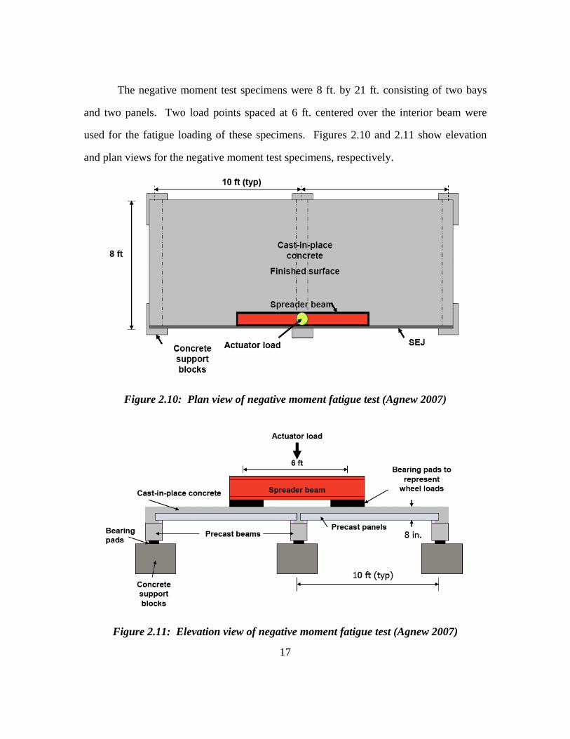
The negative moment test specimens were 8 ft. by 21 ft. consisting of two bays
and two panels. Two load points spaced at 6 ft. centered over the interior beam were
used for the fatigue loading of these specimens. Figures 2.10 and 2.11 show elevation
and plan views for the negative moment test specimens, respectively.
Figure 2.10: Plan view of negative moment fatigue test (Agnew 2007)
Figure 2.11: Elevation view of negative moment fatigue test (Agnew 2007)

18
Each specimen was first subjected to service or design level fatigue loads
followed by a static overload test after 2 million cycles. The fatigue load testing was then
continued up to 5 million cycles before finally conducting a static test to failure.
All four test specimens behaved excellently under the fatigue loading. During
each test, the stiffness of the composite slab did not change during the first 2 million load
cycles. After the static overload test, the stiffness decreased, but did not change
appreciably throughout the remainder of the fatigue loading. No delamination was
observed at the interface of the panel and the cast-in-place topping slab in any of the test
specimens. When testing to failure, all four test specimens failed in punching shear at
load levels exceeding 3.5 times design wheel loads.
2.3 SKEWED PRESTRESSED PANELS AND SLABS
In the following sections, topics involving skewed concrete bridge construction
and behavior are discussed.
2.3.1 Abendroth, Pratanata, and Singh (1991)
Under research project HR-310 for the Iowa Department of Transportation,
Abendroth, Pratanat, and Singh (1991) conducted a comprehensive research project to
investigate the performance of precast concrete panels used as part of composite bridge
deck slabs. The research project included surveys of design and fabrication agencies,
field inspections, analytical models, and full scale testing. The focus of the discussion
herein will be on the experimental testing of skewed panels and the results from the
survey.
2.3.1.1 Experimental Testing of Trapezoidal Panels
The experimental portion of research project HR-310 involved five full-scale
composite slab specimens. Three of the five specimens included skew angles of 15, 30,

19
and 40 degrees each (Figures 2.12-2.15). Each composite slab was comprised of a 2-1/2
in. prestressed concrete panel and 5-1/2 in. of cast-in-place concrete topping. The
support beams were spaced 8 ft. on center creating a 6 ft. 6 in. clear span. These
dimensions were the largest allowable spacing permitted by Iowa DOT at the time of
research. In addition to the two longitudinal support beams, the panels were supported by
a third beam running along the skewed end of the panel. The panels were supported on
3/4 in. thick by 1 in. wide fiber-board on all bearing surfaces.
Figure 2.12: Plan view of 15 degree skew test (Abendroth 1991)

20
Figure 2.13: Plan view of 30 degree skew test (Abendroth 1991)
Figure 2.14: Plan view of 45 degree skew test (Abendroth 1991)

21
Figure 2.15: Cross-section of composite specimens (Abendroth 1991)
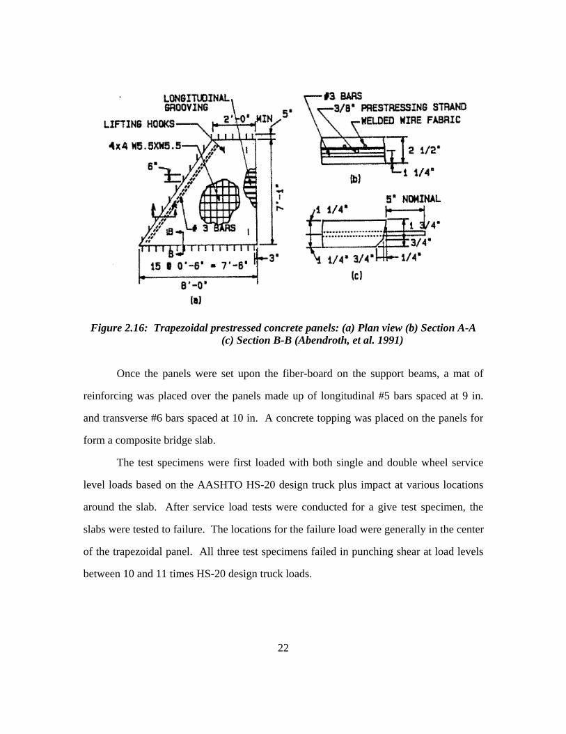
The precast concrete panels were 2-1/2 in. thick and 7 ft. 1 in. wide. The
trapezoidal panels were all 8 ft. long on the long edge whereas the short edges were 6 ft.
1-1/4 in., 3 ft. 10-7/8 in., and 2 ft. 0-5/8 in. for the 15, 30, and 40 degree skews,
respectively. The panels were prestressed using 3/8 in., 270 ksi low-relaxation
prestressing strands positioned at the mid-depth of the panel 6 in. on center. In addition
to the prestressing strands, the skewed panels had two #3 bars placed along the skewed
end and a welded wire mesh placed directly above the strands. Plan and cross-section
views of the trapezoidal panel designs are shown in Figure 2.16. The strands were
oriented transverse to the main support beams tensioned to 17.2 kips each prior to
concrete placement. To prevent the panel from cracking during the strand de-tensioning,
two, three, and four of the shortest strands passing through the acute angle of the
trapezoidal panel were sleeved on the 15, 30, and 40 degree skew panels, respectively.
The fabrication of the panels was done at a precast plant in Iowa Falls, IA.
22
Figure 2.16: Trapezoidal prestressed concrete panels: (a) Plan view (b) Section A-A (c) Section B-B (Abendroth, et al. 1991)
Once the panels were set upon the fiber-board on the support beams, a mat of
reinforcing was placed over the panels made up of longitudinal #5 bars spaced at 9 in.
and transverse #6 bars spaced at 10 in. A concrete topping was placed on the panels for
form a composite bridge slab.
The test specimens were first loaded with both single and double wheel service
level loads based on the AASHTO HS-20 design truck plus impact at various locations
around the slab. After service load tests were conducted for a give test specimen, the
slabs were tested to failure. The locations for the failure load were generally in the center
of the trapezoidal panel. All three test specimens failed in punching shear at load levels
between 10 and 11 times HS-20 design truck loads.

23
2.3.1.2 Results from Panel Questionnaires
As part of the research project, surveys containing 82 multiple choice questions
were distributed to design agencies and precast concrete plants across the United States
and Canada. The purpose of the survey was to get an understanding of how other
governing bodies permit usage of precast concrete panels during bridge construction as
well as capabilities and opinions of manufactures that have made such panels.
The questionnaires sent to 121 departments of transportation and tollway
authorities contained questions pertaining to general bridge and panel geometry, bearing
details, design criteria and specifications, economy, and experience with panel usage.
Only 29 of the 69 agencies that returned the surveys said that they have used panels in
bridge construction. The design agencies expressed concerns regarding performance,
serviceability, economy, and lack of composite bridge deck specifications by AASHTO.
Only 16 of the 29 agencies that have used panels for bridge construction were still
permitting their use at the time of the survey (1991).
Selected survey results from the questionnaires returned by design agencies
relating to skewed bridge decks and panels are as shown in Table 2.1. The numbers in
parenthesis correspond to the number of agencies reporting that answer. Considerable
variability is evident from the survey results regarding the usage of skewed prestressed
panels. Maximum skew angles and minimum short side length were reported as large as
50 degrees and as short as 1 ft., respectively. A majority of the agencies that permit the
use of skewed panels reported that no additional reinforcing is required and no
prestressing strands are de-bonded. To achieve the desired skew angle, most agencies
allow the panels to be either sawn or cast. Overall, both positive and negative feedback
was given with respect to panel usage. Many design agencies had yet to conduct an
economic analysis or evaluation of performance.

24
Table 2.1: Selected survey results from design agencies (Abendroth 1991)
1. Maximum bridge skew for panels adjacent to abutments or pier diaphragms:
(14) Not Specified (2) 15 Degree (3) 30 Degree (0) 45 Degree (4) Other [0,18,20,50 Degree]
2. For non-rectangular shaped panels that occur at abutment and pier diaphragms in
skewed bridges, what is the minimum length of a panel side?
(8) Panels not permitted at these locations (5) Not specified (0) 0 ft. (triangular shaped panel) (5) 1 ft. (trapezoidal shaped panel) (2) 2 ft. (trapezoidal shaped panel) (9) Other [Unspecified, one-half the length of the opposite side, 1.5 ft, 2.25 ft, 3 @ 3ft, 2 @ 3.25 ft]
3. Panel construction at skewed abutment or pier locations:
(8) Panels are not used at these locations (4) Panels sawn to match the skew only (2) Panels cast to match the skew only (12) Panels sawn or cast to match the skew (4) Other [Panels not used when skew > 15 deg., C.I.P. full depth, C.I.P. slab if skew > 30 deg., May also cast closure in place without panel]
4. For non-rectangular panels, what type of additional reinforcement, other than the conventional rectangular panel reinforcement, is provided in the panel?
(8) Non-rectangular panels are not permitted (15) None (2) R/C bars only (0) Wire Strands (1) WWF only (0) Any of the above (1) Other [Unspecified]
5. For a non-rectangular shaped panel, are some strands unbonded near the panel ends?
(6) Only rectangular shaped panels are permitted (0) Always (0) Sometimes (21) Never

25
The surveys sent to 192 different manufacturers addressed topics relating to
experiences, general bridge and panel geometry, design criteria and specifications,
economy, inspections, and opinions. Of the 72 producers who returned the
questionnaires, only 27 claimed they had made precast concrete panels for bridges.
Many of the fabricators who said they did not make panels gave reasons such as local
preference for cast-in-place bridge decks, difficult quality control, not economical, and
competition within the market.
Selected survey results from the questionnaires returned by manufacturing
agencies relating to skewed bridge decks and panels are as shown in Table 2.2. The
numbers in parenthesis correspond to the number of agencies reporting that answer.
Again, great variability is seen regarding the manufacturing of precast panels. The
minimum panel edge length received a wide variety or answers ranging from as little as 0
ft to a maximum of 4 ft. Two, three, and four manufacturers reported maximum skew
angles of 15, 30, and 45 degrees, respectively, whereas 10 claimed there was no
maximum as long at the short side is 1 ft. wide. Eleven of the 20 producers who
construct skewed panels reported using additional mild reinforcing bars along the skewed
end. Casting the panels to match the desired skew angle was the most common method
of construction, but several other manufactures reported sawing the panels to achieve the
skew angle. When asked their opinion about skewed precast panels, some agencies
claimed that the panels were difficult to de-tension and set properly. Additionally, many
producers felt that precast panels would require better standardization and details to
become an economic alternative. Nonetheless, when rating the overall panel usage, 19 of
the 24 respondents reported a rating between Good and Excellent.

26
Table 2.2: Selected survey results from manufacturing agencies (Abendroth 1991)
1. For non-rectangular shaped panels that occur at abutment and pier diaphragms
in skewed bridges, what is the minimum length of a panel side?
(6) Only rectangular panels are cast [Mostly saw cut in the field] (4) 0 ft. (triangular shaped panel) (3) 1 ft. (trapezoidal shaped panel) (7) 2 ft. (trapezoidal shaped panel) (9) Other (trapezoidal shaped panel cast) [1 ft, 2.83 ft, 3 @ 3 ft, 4 ft]
2. Panel construction at skewed abutment or pier locations: (3) Panels are not used at these locations (3) Panels sawn to match the skew only (12) Panels cast to match the skew only (7) Panels can either be sawn or cast to match the skew (4) Other [N.A.]
3. For non-rectangular panels, what type of additional reinforcement, other than the conventional rectangular panel reinforcement, is provided in the panel?
(6) Only rectangular panels without additional reinforcement are cast (5) None (2) Prestressing strands only (1) WWF only (11) Reinforcing bars only [Extra No. 4 bars, 8 No. 5 bars along future cutted skew location] (1) Other [Varies with job]
4. Maximum skew angle for casting non-rectangular panels to match the bridge skew for those panels adjacent to abutment or pier diaphragms:
(6) Only rectangular panels are cast (2) 15 Degree (3) 30 Degree (4) 45 Degree (10) No maximum [Minimum edge length of 1 ft, No pointed corners] (1) Other [As long as the ratio of the long to short panel end is 2 or less]
5. For a non-rectangular shaped panel, are some strands unbonded near the panel ends?
(6) Only rectangular shaped panels are cast (0) Always (5) Sometimes (14) Never

27
2.3.2 Rajagopalan (2006)
In his book Bridge Superstructure, Rajagopalan presents a chapter on the design
of skew slab bridge decks. Although the post-tensioned slab bridge decks discussed are
much larger than precast panels and typically parallelogram-shaped, the concepts
presented are relevant.
For rectangular slab bridge decks, the principle moments act in the longitudinal
and transverse directions with respect to the supports. Loads placed on the slab are
transferred to the support directly through flexure. A small amount of torsion exists due
to the unsupported edges, but the effect is negligible. For skewed slabs, however, the
slab primarily bends along a line between the two obtuse angled corners. The width of
this bending strip is a function of the skew angle and ratio of slab width to length. Loads
placed to either side of this strip are not transferred directly to the supports; rather they
are transferred to the strip in a cantilevered manner. This cantilevered transfer of forces
can cause very large twisting moments on the strip with high skew angles. Diagrams
showing the stress trajectories for various skew angles are shown in Figure 2.17.
The deflections and reactions resulting from torsion within the slab are not
uniform or symmetrical. As the skew increases, the maximum deflection on the free end
of the slab gets closer to the obtuse angled corner. A majority of the load is transferred to
the obtuse angled corner and in the case of large skews, the acute angled corners can
actually experience uplift. Diagrams showing deflection profiles in different regions of a
skewed slab bridge deck are given in Figure 2.18.

28
Figure 2.17: Principle stress trajectories for various skews (Rajagopalan 2006)
Figure 2.18: (a) Deflection profile in a skewed deck (b) 'S' shaped deflection profile near the support line for large skew angles (Rajagopalan 2006)

29
Because the principle moments are parallel to the strip between obtuse-angled
corners, conventional post-tensioning oriented parallel to the free edges is not the most
effective. Instead, differential post-tensioning would better counteract the higher
moments around the obtuse-angled corner and lower moments around the acute-angled
corner. This could be achieved by using a fan-shaped strand layout where strands are
spaced closely together near the obtuse-angled corner and further apart around the acute-
angled corner. A plan view of a fan-shaped strand pattern is shown in Figure 2.19.
Figure 2.19: Fan-shaped post-tensioning cable layout (Rajagopalan 2006)
30
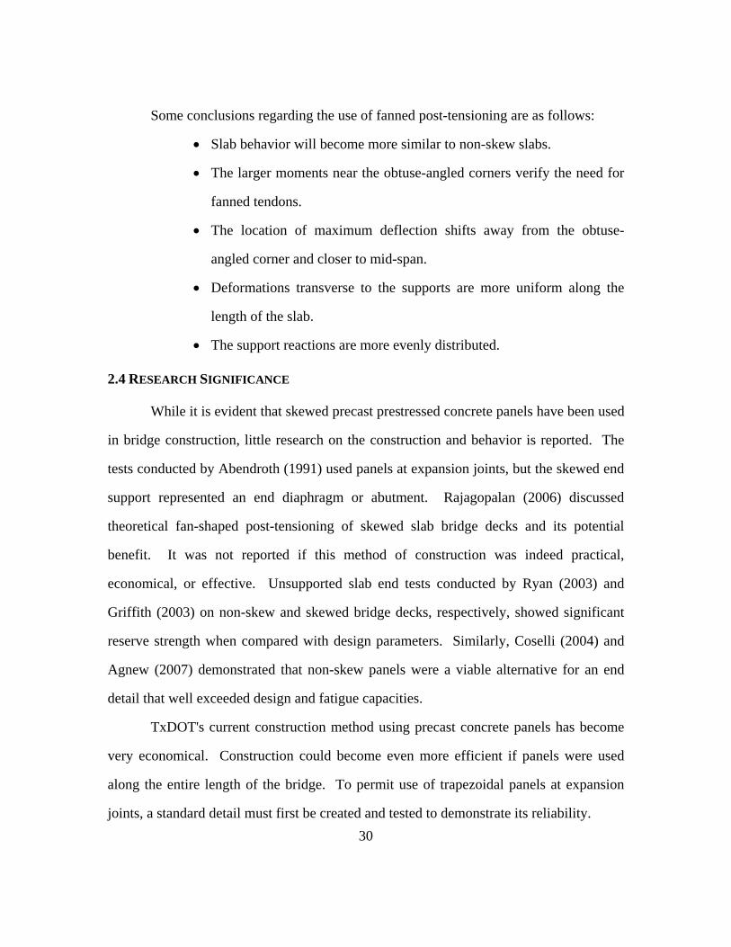
Some conclusions regarding the use of fanned post-tensioning are as follows:
• Slab behavior will become more similar to non-skew slabs.
• The larger moments near the obtuse-angled corners verify the need for
fanned tendons.
• The location of maximum deflection shifts away from the obtuse-
angled corner and closer to mid-span.
• Deformations transverse to the supports are more uniform along the
length of the slab.
• The support reactions are more evenly distributed.
2.4 RESEARCH SIGNIFICANCE
While it is evident that skewed precast prestressed concrete panels have been used
in bridge construction, little research on the construction and behavior is reported. The
tests conducted by Abendroth (1991) used panels at expansion joints, but the skewed end
support represented an end diaphragm or abutment. Rajagopalan (2006) discussed
theoretical fan-shaped post-tensioning of skewed slab bridge decks and its potential
benefit. It was not reported if this method of construction was indeed practical,
economical, or effective. Unsupported slab end tests conducted by Ryan (2003) and
Griffith (2003) on non-skew and skewed bridge decks, respectively, showed significant
reserve strength when compared with design parameters. Similarly, Coselli (2004) and
Agnew (2007) demonstrated that non-skew panels were a viable alternative for an end
detail that well exceeded design and fatigue capacities.
TxDOT's current construction method using precast concrete panels has become
very economical. Construction could become even more efficient if panels were used
along the entire length of the bridge. To permit use of trapezoidal panels at expansion
joints, a standard detail must first be created and tested to demonstrate its reliability.
31
CHAPTER 3
Design of Test Specimens
3.1 INTRODUCTION
The objective of the experimental program was to evaluate the constructibility
and practicality of producing skewed prestressed panels for use at expansion joints. In
the investigation of a new product, many variables may need to be tested or held
constant. The areas of primary concern included the skew angle, panel dimensions, and
prestressing strand arrangement. Additional variables included prestressing force,
concrete release strength, and supplementary deformed reinforcing bars for bursting or
flexural reinforcement.
3.2 PRELIMINARY DESIGN
In September 2006, the research team held a joint meeting with representatives
from TxDOT's bridge division, local precast concrete panel fabricators, and bridge
construction contractors. The objective was to determine if contractors had an interest in
skewed panels, if the fabricators could produce such panels, and if the requirements of
TxDOT's bridge division could be satisfied. At the joint meeting, the discussion was
open for any ideas from TxDOT, fabricators, or contractors. The main topics discussed
were the panel geometries and methods of reinforcement. Several basic concepts came
from this meeting and set the initial outline from which planning could proceed. A
follow-up meeting held in November 2006 with the TxDOT representatives to establish
the test parameters.
32
3.2.1 Panel Geometry
The most feasible panel geometries presented were:
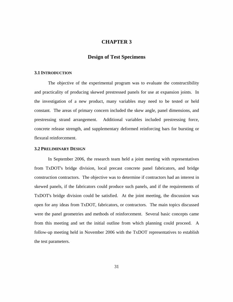
• Option 1 - One large trapezoidal panel (Figure 3.1). Using a single panel to make
the skew angle transition would require the fewest custom panels and minimize
construction awkwardness. However, panels with large angles and widths cannot
be produced on current prestressing beds and would require construction of new,
wider ones. Also, depending on the orientation of the prestressing, some of the
strands may have embedment lengths shorter than required to transfer forces into
the panel. Areas with such strands might not provide the necessary strength.
Figure 3.1: Option 1 - Single trapezoidal panels
Conventional Panels
Trapezoidal Panels

33
• Option 2 - System of two, smaller trapezoidal panels (Figure 3.2). By breaking
up the skew angle transition into two panels, each panel would be small enough to
fabricate on current prestressing beds. As well, smaller angles on each panel may
result in fewer strands lacking the proper embedment length. The downside to
this method is that twice as many custom panels are required and construction
crews have to manage the placement of more awkwardly shaped panels.
Figure 3.2: Option 2 - Combination of two trapezoidal panels
Conventional Panels
Trapezoidal Panels
34
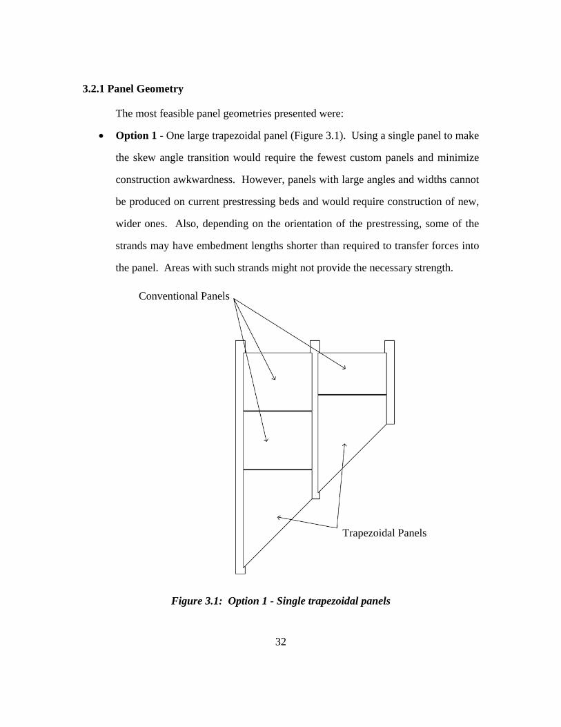
• Option 3 – Quadrilateral panel with parallel sides at expansion joint followed by
trapezoidal panel (Figure 3.3). By making the edge panel a parallelogram, current
prestressing beds could be used with skewed formwork. However, the second,
trapezoidal shaped panel would still require a new casting bed for large skew
angles and beam spacing, just like that in Option 1. The main benefit of this
method would be to ensure a fully prestressed panel at the expansion joint.
Furthermore, regions in the trapezoidal panels containing strands without
sufficient embedment would be away from the expansion joint.
Figure 3.3: Option 3 – Combination of quadrilateral and trapezoidal panels
Conventional Panels
Trapezoidal Panels
Quadrilateral Panels

35
3.2.2 Reinforcement Alternatives
As mentioned in the panel options, the trapezoidal shaped panels have several
different reinforcement alternatives. Considering typical casting bed layouts, prestressing
strands could be oriented either perpendicular to the girders, parallel to the girders, or
parallel with the skewed expansion joint. In each case, supplemental reinforcement
would need to be placed at locations without effective prestressing. Figures 3.4 and 3.5
show different prestressing arrangements with the supplementary deformed
reinforcement that would be needed. Another alternative that would not require any
additional deformed bars is shown in Figure 3.6. By flaring the strands throughout the
panel, strands are parallel to both the skewed and non-skewed ends. In each figure,
strands that do not meet the embedment length requirement were omitted to show
partially prestressed locations. Furthermore, typical temperature and shrinkage
reinforcement required for panels is not shown.
Figure 3.4: Strands oriented perpendicular to the girders

36
Figure 3.5: Strands oriented parallel to the skewed end
Figure 3.6: Strands flared throughout panel
In addition to prestressed panels, a conventionally reinforced panel and a post-
tensioned panel using dywidag bars were discussed. The conventionally reinforced panel
option was eliminated due to crack control requirements under the weight of the cast-in-
place topping slab. Cracking would most likely occur and TxDOT engineers did not find

37
that acceptable. The post-tensioned panel was rejected, as well, because of complications
with anchorage and bar sizes.
3.2.3 Construction Issues
In general, contractor and fabricator representatives expressed support for the
possibility of using skewed panels. However, they indicated that there were limitations
on their capabilities that would restrict using some of the proposed alternatives.
Additionally, TxDOT, as the owner of the structures, has established standards for the
panels currently being used.
3.2.3.1 Contractor Requests
The contractors were in unanimous agreement that using skewed panels at
expansion joints would benefit the construction process. The panels would eliminate the
additional time used to form and shore the current IBTS detail, as well as the time
required to remove such forms. In certain circumstances, such as over water, removal of
formwork from the underside of the bridge can become costly and time consuming.
Additionally, eliminating the temporary hole in the unfinished bridge deck before the
formwork is in place at expansion joints could reduce insurance costs and create a safer
work environment. The contractors also claimed they would willingly pay a premium, if
necessary, for the specialty panels. The primary requests were to use a single panel and
limit the panel weight to 6,000 pounds. Using a single panel between each girder would
reduce the handling and setting of awkward panels. By limiting the weight of the panels,
the contractors would not have to upgrade the cranes or other equipment currently used to
place panels. The contractors also rejected the idea to saw cut standard panels to custom
angles because saw blades wear down quickly while cutting through prestressing strands.

38
Another area of concern associated with using panels at expansion joints was the
permitted spacing between panels. Using the current IBTS detail, formwork can easily
be constructed to match the location of the end panel (Figure 3.7a). With a precast panel,
however, geometric control in setting panels becomes more important because the panel
dimensions on site are fixed. A strip of compressible foam, known as backer rod, is
typically used to fill any gaps between panels up to 3/4 in., but a gap in this situation
could become too large if the geometry control is not accurate (Figure 3.7b). One
proposed alternative is to saw-cut two conventional rectangular panels on site for a
custom fit (Figure 3.7c). Because the cut would be oriented parallel to the strands, the
saw blade would last longer.

39
Figure 3.7: (a) Current construction techniques (b) Construction issue with end panels (c) Possible solution using two field-sawn panels
Conventional 8' Panel
Conventional 8' Panel
Conventional 8' Panel
Easily Adjusted Length
Formwork
Potential Panel Mis-fit
Trapezoidal End Panel
Saw-cut Rectangular Panels
Trapezoidal End Panel

40
3.2.3.2 Fabricator Capabilities
The fabricator representatives indicated that producing skewed panels would not
be difficult. They could easily produce custom wooden formwork for a given panel
geometry as well as de-bond any strands necessary. De-bonding would be required if
strands do not meet the minimum embedment length needed to transfer the prestressing
force. The main problem they face is that the long lines used at the prestressing plants to
produce the panels are permanently set to an 8 ft. width due to shipping restrictions.
Anything wider than 8 ft. would necessitate special truck permits and cost extra money.
However, many fabricators agreed that if the contractors were willing to pay the premium
for the skewed panels, they would construct a new, wider casting bed to accommodate a
wider panel dimension. Moreover, the fabricators claimed they could handle the shipping
restrictions. These capabilities are dependent on the skewed panels having strands
parallel to one another. For the flared prestressing strand alternative, no fabricator input
was given. It was assumed that specialty casting beds would need to be constructed that
would preclude mass production similar to current long-line methods.
3.2.3.3 TxDOT Requirements
The TxDOT bridge division representatives suggested that the panels utilize the
current precast concrete panel standards as much as possible. This included concrete
strength, the prestressing strand size, additional mild steel reinforcement, concrete release
strength, panel thickness, and all bedding strip requirements (Figures 3.8 and 3.9). The
other main variables were panel width, skew angle, and the short edge bearing length.
Regardless of fabrication technique, the requirements needed to be flexible enough to
accommodate variable skew angles and beam spacing. Current construction practice
utilizes bedding strips with 40 or 60 psi strength, therefore, the TxDOT representatives
wanted to keep bearing pressures within this range so that special materials need not be

41
specified. Additionally, TxDOT expressed their concern for crack control at service load
and preferred to see the prestressing strands parallel to the skewed end of the panels.
Figure 3.8: Prestressed concrete panel bearing details

42
Figure 3.9: Prestressed concrete panel standard details

43
3.2.4 Selected Designs
Considering all of the options and opinions presented at the meetings, two types
of skewed panels were selected to investigate. Because of the contractor requests, both
types would be single trapezoidal panels that encompass the entire skew angle. The first
alternative selected was the flared prestressing pattern. The second alternative has the
prestressing parallel to the skewed edge with additional reinforcement perpendicular to
the girders.
The current TxDOT maximum girder spacing is 10 ft. on center with a 9 ft. clear
span between top flanges. With the minimum overhang of a precast panel over a flange
equal to 3 in., the maximum panel width becomes 9 ft. 6 in. A new line of girders, TX-
sections, that will soon be utilized in bridge designs permits girder spacing to extend up
to 11 ft. on center. However, the new girders have wider top flanges creating an 8 ft.
clear span between flanges. Therefore, a worst case condition of a 9 ft. 6 in. panel width
was selected. Sketches of the two panel design options are shown in Figure 3.10.
Figure 3.10: Selected design alternatives
Flared Prestressing Prestressing Parallel to Skewed End

44
In order to select a skew angle for design, bridge survey data from all bridges in
Texas provided by TxDOT was reviewed. As seen in Table 3.1, targeting a 45 degree
skew angle would encompass 97.9% of all bridges and 96.2% of prestressed I-girder
bridges. This clearly covers a majority of bridge designs, therefore a 45 degree skew
angle was chosen for the test program. Histograms showing the number of bridges with
given skew angles are shown in Figures 3.11 and 3.12.
Table 3.1: Bridge skew angles in Texas
Pretensioned
I-Girders All Bridge Types
Total Bridges 8004 33201 Skew # % # %
0° 3877 48.4% 21376 64.4% ≤ 15° 5095 66.7% 24058 73.6% ≤ 30° 6310 85.0% 28003 87.1% ≤ 45° 7055 96.2% 31164 97.9%
Pretensioned I Grider Bridges
0
50
100
150
200
250
300
350
400
450
500
01 05 09 13 17 21 25 29 33 37 41 45 49 53 57 61 65 69 73 77Skew Angle
Num
ber o
f Brid
ges
Figure 3.11: Number of pretensioned I-girder bridges with given skew angles (Van Landuyt 2006)
Pretensioned I-Girder Bridges

45
All Bridge Types
0
500
1000
1500
2000
2500
01 05 09 13 17 21 25 29 33 37 41 45 49 53 57 61 65 69 73 77Skew Angle
Num
ber o
f Brid
ges
Figure 3.12: Number of all bridge types with given skew angle (Van Landuyt 2006)
Lastly, the short edge bearing length was determined based on bearing pressure
calculations. For these calculations, the weight of the panel was conservatively assumed
to have equal distribution to each girder. Furthermore, the bearing pressures were taken
as equal along the length of each girder. Both 40 psi and 60 psi foam bedding strips are
used in bridge construction, but 40 psi foam was selected as the more critical case. When
using the TxDOT specified minimum width for rectangular panels of 34 in., bearing
pressures for panels with large skew angles exceed 40 psi as shown in Table 3.2. Using
the data shown in Table 3.3 the minimum bearing length of 55.8 in. for a 45 degree skew
panel was rounded up to 60 in. for simplicity.

46
Table 3.2: Bearing pressures using TxDOT minimum 34 in. bearing length
Bearing Pressures Using 34" Short Edge Length Angle
(degrees) Short Edge Length (in)
Panel Weight (lbs)
Total Load (lbs)
Pressure (psi)
45 34 3602 7204 53 40 34 3239 6478 48 35 34 2926 5851 43 30 34 2648 5297 39 25 34 2398 4796 35 20 34 2167 4334 32 15 34 1950 3901 29 10 34 1744 3487 26 5 34 1543 3086 23
Table 3.3: Minimum short edge bearing lengths for 40 psi and 60 psi bedding strips
Required Short Edge Lengths Angle
(degrees) Foam
Strength (psi) Panel
Weight (lbs) Total
Load (lbs)Short Edge Length (in)
45 40 4466 8932 55.8 40 40 3747 7495 46.8 35 40 3127 6254 39.1 30 40 2578 5157 32.2 45 60 3367 6734 28.1 40 60 2825 5650 23.5 35 60 2357 4715 19.6 30 60 1944 3888 16.2
3.3 FLARED PRESTRESSING PATTERN
The first two specimens were designed using the flared prestressing pattern so that
the entire panel was fully prestressed. The basic arrangement of the strands for this
alternative is shown in Figure 3.6. The following sections describe the final design.

47
3.3.1 Strand Layout
As noted previously, the width of the panel was set to 9 ft. 6 in. with a 45 degree
skewed end and 60 in. short edge length. This set the basic geometry from which to
design the prestressing strand locations. The goal for this design was to produce a
uniform peak stress along the length of the panel when loaded with fresh concrete during
deck placement. Casting the topping slab for the deck was seen as a critical loading
condition for the panel since it carries the entire load. Keeping the panel uncracked
during this phase is essential to satisfactory long term performance. Once the topping
slab is cured, the panel and slab act compositely.
In the flared pattern, the embedment length of each individual strand varies. This
leads to slight differences in seating loss, elastic shortening, creep and shrinkage, and
strand relaxation. Analysis using the strip method with trapezoidal-shaped sections was
done to determine the exact spacing between strands. Because the strips analyzed were
trapezoidal, the effective prestressed area varied along the length of the strip. This led to
a non-uniform prestressed force from one edge of the panel to the other. The strand
spacing on the short edge of the panel was set to 3 in. on center to reduce local stresses
and provide more space for the chuck and barrel anchoring assemblies. The selected
strand spacing is shown in Figure 3.13.
Using ACI 318-05, the maximum allowable tensile stress in prestressing steel due
to the jacking force is 0.94 times the yield stress. The yield stress for prestressing strands
is approximately 0.85 times the ultimate strength. Using 270 ksi prestressing steel, the
maximum allowable stress becomes 215.7 ksi, which equals a jacking force of 18.3 kips
on a 3/8 in. strand with cross sectional area of 0.085 in2. Because seating losses are much
more critical for shorter strands, a target jacking force of 18 kips was selected instead of
the 16.1 kips specified on the precast panel standard drawings. A seating loss of 1/4 in.

48
was assumed, which could reduce the strand stress by as much as 20% for short strands.
Creep and shrinkage coefficients of 2.9 and 0.0008 were selected and modified for a 60
day time frame to 1.56 and 0.000417, respectively.
Figure 3.13: Strand spacing for flared strand pattern
3.3.2 Additional Mild Reinforcement
In the flared prestressing pattern, no two strands within the panel were parallel to
each other. It was believed that this varying vector of compressive load would result in a
splitting action between strands. No additional bursting steel is required for the current

49
panels, but it is typical in other prestressing applications to prevent rupture and control
cracking. To account for these conditions, #3 bars bent 180 degrees (hairpins) were
placed between strands. A single hairpin bar could span the gap between several strands,
so an equal number of bars to strands were not necessary. The hairpins arrangement,
shown in Figure 3.14, was chosen so that they crossed the strands as close to orthogonal
as possible.
Figure 3.14: Hairpin layout for flared strand pattern
The first test specimen had 12 hairpins on the short edge and 8 on the long edge.
Because the strands were spaced much further apart on the long edge, fewer hairpins
were necessary. The second test specimen did not contain any hairpins in order
determine whether they were necessary. To fulfill the longitudinal panel reinforcement
requirements, #3 deformed bars spaced at 6 in. on center were used in each test specimen.
Hairpin (typ)
3/8" 7-Wire Strand (typ)

50
3.3.3 Release Strength
The TxDOT standard for concrete release strength in precast panels is 4,000 psi.
Because of the high local compressive force at the obtuse and acute angles in the skewed
panel, the first test specimen had a target release compressive strength of 5000 psi. The
target compressive strength at release for the second specimen was 4,000 psi in order to
match the current TxDOT standard for precast panels.
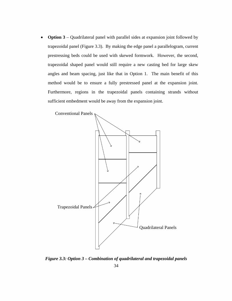
3.4 PARALLEL PRESTRESSING PATTERN
The second set of test specimens was designed with a prestressing arrangement in
which the strands are parallel to one another as well as the skewed end. To account for
partially prestressed or non-prestressed portions of the panel due to lack of strand
embedment, supplemental deformed reinforcement was placed in this region.
3.4.1 Panel and Strand Geometry
Similar to the flared prestressing panels, the width of these panels was set to 9 ft.
6 in. to capture the largest beam spacing possible. Likewise, a skew angle of 45 degrees
was chosen to include a majority of bridges in Texas. The first test specimen with the
parallel strand arrangement had a short edge length of 60 in. to maintain continuity with
the flared strand panels. Because this strand arrangement facilitates fabrication of
smaller panels, the short edge length was reduced to 45 in. in a second specimen for
comparison.
The motivation behind the strand layout was to match the current precast panel
standard and casting lines at fabrication plants. Therefore, the strand spacing for the
parallel pattern was set at 6 in. on center. A triangular region of the panel contains
strands that do not meet the required embedment length to transfer the prestressing force.
Using ACI 318-08 equation 12-4, 3/8 in. strands tensioned to 16.1 kips require

51
approximately 24 in. of embedment to transfer the force. Fabricators typically use a de-
bonding agent or simply wrap the strand when no force transfer is desired. For these test
specimens, any strand that would have an embedment length less than 48 in. was omitted
(24 in. from each face of the panel). As a result, the first test specimen with a 60 in. short
edge length required 14 strands spaced at 6 in. The second test specimen only required
12 strands since the short edge length was 15 in. shorter. The strand layouts for both
designs are shown in Figure 3.15.
Figure 3.15: Parallel strand panel designs
3.4.3 Additional Mild Reinforcement
The strand spacing in these test specimens matched that of the TxDOT standard
panels, so no additional bursting steel was used. However, these test specimens
contained an entire corner region where no prestressing was present. To account for this,
52
additional transverse mild steel reinforcing was used. To achieve a higher bending
strength, the bars were placed beneath the prestressing strands. However, due to cover
restrictions, the size of the bar was limited. The final design consisted of placing #4 bars
with a 4 in. center to center spacing parallel to the non-skewed end. The number of bars
used was selected to cover the entire non-prestressed region. The first specimen with the
60 in. short edge contained 14 transverse bars and the second specimen with a 45 in. short
edge used 11 transverse bars. To fulfill the longitudinal reinforcement requirements, #3
deformed bars spaced at 6 in. were used in each test specimen. The ordinary reinforcing
layouts for both designs are shown in Figure 3.16.
Figure 3.16: Additional deformed bars in parallel strand panels
3.4.4 Commercial Fabrication
In addition to the four test specimens fabricated by the researchers, another set of
test specimens was fabricated by a precast plant. The design matched the 45 degree skew
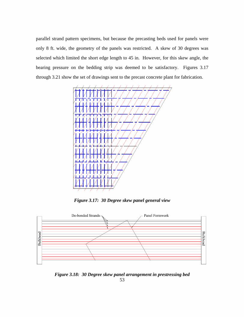
53
parallel strand pattern specimens, but because the precasting beds used for panels were
only 8 ft. wide, the geometry of the panels was restricted. A skew of 30 degrees was
selected which limited the short edge length to 45 in. However, for this skew angle, the
bearing pressure on the bedding strip was deemed to be satisfactory. Figures 3.17
through 3.21 show the set of drawings sent to the precast concrete plant for fabrication.
Figure 3.17: 30 Degree skew panel general view
Figure 3.18: 30 Degree skew panel arrangement in prestressing bed

54
Figure 3.19: 30 Degree skew panel dimensions
Figure 3.20: 30 Degree skew panel prestressing

55
Figure 3.21: 30 Degree skew panel ordinary reinforcing layout and detail
3.5 Design Summary
A total of eight prestressed panels were produced using five different designs. All
45 degree skew panels were fabricated within Ferguson Laboratory. The 30 degree skew
panels were commercially fabricated. Table 3.4 provides a summary of all panels
produced. The nomenclature used to identify the panels is as follows: 1) Prestressed
panel (P), 2) 30 degree (30) or 45 degree (45) skew, 3) Flared (F) or Parallel (P) strands,
4) 45 in. (45) or 60 in. (60) short edge bearing length. The number following the dash

56
indicates the specimen number using that panel design. For example, the second panel
with a 45 degree skew using the flared prestressing pattern and a 60 in. short edge length
is designated P45F60-2.
Table 3.4: Summary of panel designs
Panel Name
Skew Angle
(Degrees)
Short Edge Length (Inches)
Strand Pattern
Supplementary Reinforcement
Release Strength
(psi)
P45F60-1 45 60 Array Hairpins 5000 P45F60-2 45 60 Array None 4000 P45P60-1 45 60 Parallel Flexural 4000 P45P45-1 45 45 Parallel Flexural 4000 P30P45-1 30 45 Parallel Flexural 4000 P30P45-2 30 45 Parallel Flexural 4000 P30P45-3 30 45 Parallel Flexural 4000 P30P45-4 30 45 Parallel Flexural 4000
3.6 CONCRETE MIX DESIGN
The TxDOT required 28-day strength for precast panels is 5,000 psi. The mix
design for the test specimens was obtained from a local panel fabricator in order to
emulate typical practice. Because precast concrete plants rely on quick product turnover,
Type III cement is used to achieve high early strengths. As a result, the 28-day strength
of the mix design used was 7,500 psi. The concrete cubic-yard batch weights are shown
in Table 3.5. The weights for the aggregates are based on saturated surface dry (SSD)
conditions.
Table 3.5: Concrete mix design properties
Cement (lbs/yd3)
SSD Fine Aggregate (lbs/yd3)
SSD Coarse Aggregate (lbs/yd3)
Water (lbs/yd3)
Super Plasticizer (oz./100lb Cement)
Retarder (oz./100lb Cement)
658 1276 1776 250 6 4

57
CHAPTER 4
Prefabrication Activities
4.1 INTRODUCTION
Before fabrication of trapezoidal prestressed panels could begin, production
methods had to be developed. First, the construction of a self-reacting prestressing frame
and the strand anchorage system is described. Next, the strand stressing operation and
methods used to monitor stress levels, including instrumentation and calibration, are
discussed. The concrete batching process and the techniques used to monitor early
strength gain are also explained. Lastly, the procedure for releasing the strands once the
concrete is cured sufficiently is discussed.
4.2 PRESTRESSING FRAME
With no fabricator in Texas currently equipped to produce a skewed prestressed
panel, a self-reacting prestressing frame was designed and constructed for production of
the panels at Ferguson Laboratory. The frame needed to contain a large open casting bed
and to resist significant eccentric loads produced by the tensioned strands. Because the
strands in the arrayed prestressing pattern are skewed relative to each other (Figure 4.1),
the forces are multi-directional. With the help of RISA-3D modeling, the prestressing
frame was designed using relatively small wide-flange and channel sections. These
shapes were selected because they were relatively easy to handle, modify, and transport
with the facilities available in Ferguson Laboratory.
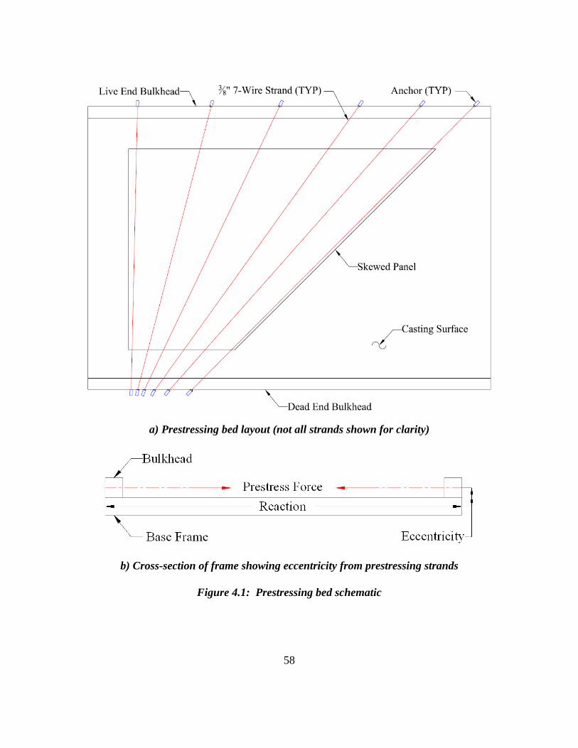
58
a) Prestressing bed layout (not all strands shown for clarity)
b) Cross-section of frame showing eccentricity from prestressing strands
Figure 4.1: Prestressing bed schematic

59
4.2.1 Base Reaction Frame
The main structural frame for the prestressing bed consisted of W8x24 steel
shapes. An ‘X’ pattern was chosen because it most efficiently resisted the large racking
forces imposed by the skewed strands. A flat surface was essential to the placement of
other frame elements so full penetration welds were used at all connections instead of
bolted gusset plates. The arrangement of the elements in the base reaction frame is
shown in Figure 4.2 and the completed frame is shown in Figure 4.3.
Figure 4.2: Base reaction frame

60
Figure 4.3: Completed base reaction frame
Covering the frame with thin steel plates to produce a casting surface was not a
practical alternative for handling and economic reasons. Instead, a series of wide
channels, C12x20.7 were selected because of their large width and small height (2.5 in.).
These C12x20.7 shapes helped minimized the eccentricity of the load from the strands
with respect to the frame. The channels were spaced at 19 in. to help provide a flat
surface with minimal gaps. Figures 4.4 and 4.5 show elevation and plan views of the
channel floor beams, respectively. A plywood decking was placed over the channels for
a casting surface. The channels were attached at all intersections with the base reaction
frame using fillet welds to help brace the base frame.
Figure 4.4: Elevation of base frame with channel floor beams

61
Figure 4.5: Plan view of base frame with channel floor beams
4.2.2 Bulkheads
Typical prestressing beds are built with bulkheads at either end denoted live end
or dead end. The live end indicates at which end the tensioning will take place. The
strand ends on the dead end are permanently anchored throughout the process. For ease
of accessibility, the short edge of the trapezoidal panels was selected to always face the
dead end bulkhead. Because the strands in the flared prestressing pattern pass through
the bulkhead at variable angles, holes could not easily be drilled through a thick plate as
is typically done in prestressing frames. Instead, back-to-back C8x18.75 sections were
used with a 1 in. spacing between enabling strands to pass through freely. The shallow 8
in. section helped to reduce congestion of the anchors on the short edge of the panel by
minimizing the distance between the face of the panel and the anchor location. Because
the skewed strands converge onto one another as they extend from the short edge, this
distance becomes critical. An illustration of this problem is shown in Figure 4.6.

62
Figure 4.6: Overlapping dead end anchorages
In order to transfer the prestressing force to the structural steel base frame, the
back-to-back C8x18.75 channels were bolted to the top flanges of the W8x24 wide-
flange members of the base frame using high strength threaded rods as shown in Figure
4.7. Four 1-1/8 in. rods were used at every intersection with a decking channel on the
dead side because of the grouping of strands over a short distance. Only two rods were
used on the live end where the strands were spaced further apart. In the areas where
strands also pass through the bulkhead, the bolts had to be precisely placed in order to
avoid intersecting the strands.
To help transfer the shear force into the reaction frame, an additional 6 in. by 4 in.
by 1/2 in. thick angle was placed on the inside of the bulkhead. This angle was bolted
down to the decking channels using 6 bolts at every intersection. This was a stronger
alternative than welding the bottom edge to the channels. The 4 in. leg of the angle was
cut to 1-1/2 in. using a track torch so as not to obstruct the gap between the back-to-back
channels. The completed casting bed with bulkheads is shown in Figure 4.8.

63
Figure 4.7: Cross-section of dead end bulkhead
Figure 4.8: Prestressing bed prepared for flared panel fabrication
Dead End
Live End

64
4.2.3 Anchoring
Standard multi-use chuck and barrel assemblies were used for anchoring the
strands on both the dead and live ends. These assemblies consist of a set of wedges to
grip the strand set inside a tapered steel cylinder with a spring loaded cap as shown in
Figure 4.9. Due to the uniqueness of the flared prestressing pattern, a special bearing
system for the chuck and barrels had to be designed. A similar, simplified design was
used with the parallel prestressing pattern.
Figure 4.9: Typical chuck and barrel anchoring assemblies
4.2.3.1 Flared Prestressing Pattern
Devising a way to anchor twenty prestressing strands at different angles was
challenging since it would have been nearly impossible to produce and set bearing plates
with the precision required. Additionally, the anchoring region on the dead end was very
congested because the distance between the non-parallel strands reduces as the distance
from the panel increases. The solution was to use very thin spherically dished washers
(Figure 4.10) in conjunction with angled shims and simple bearing plates. Because the

65
washers had a rotational capacity of +/-2.5 degrees with the 3/8 in. strand, the angled
shims were cut to the nearest 5 degree increment of the desired angle. With this system,
the barrels aligned themselves during the stressing operation. The bearing assemblies
were constructed by welding half of the spherical washer onto one side of a 3/8 in. thick
bearing plate containing a 9/16 in. hole. The angled shim plates were then welded to the
other side of the bearing plate. A sketch of a typical bearing assembly is shown in Figure
4.11. The entire bearing assembly was welded onto the bulkheads to resist the high shear
forces associated with stressing. To further reduce congestion, a set of narrow chuck and
barrel assemblies was used on the dead end while ordinary assemblies were used on the
live end. Photos of the completed dead and live end anchorages are shown in Figures
4.12 and 4.13, respectively.
Figure 4.10: Spherically dished washers with diagram showing rotational capacity
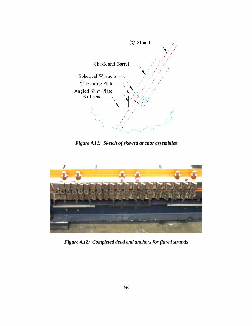
66
Figure 4.11: Sketch of skewed anchor assemblies
Figure 4.12: Completed dead end anchors for flared strands

67
Figure 4.13: Portion of completed live end anchors for flared strands
4.2.3.2 Parallel Prestressing Pattern
All of the strands in the parallel prestressing arrangement were the same angle
with respect to the bulkhead, making bearings less complicated. Bearing seats were cut
out of 2 in. thick plate to match the required angle. Holes were drilled through the blocks
to permit the strand to pass through. The bearing blocks were then welded directly to the
bulkheads to resist the shear forces from stressing. Photos of the typical bearings are
shown in Figures 4.14 and 4.15. No dished washers or shim plates were necessary
because the angle created by the bearing block was accurate enough. Instead, the chuck
and barrel assemblies were seated directly against the bearing blocks.

68
Figure 4.14: Typical bearing for parallel strands
Figure 4.15: Plan view of typical bearing for parallel strands
4.2.4 Modifications
During the first stressing operation the prestressing frame began to deform. Due
to the large diagonal, eccentric forces from the strands, opposing corners in line with the
longest strand lifted off the ground. To prevent this problem from recurring, large steel
plates were welded to the bottom of the frame so that the entire bed could be bolted to the
floor (Figure 4.16). No further uplift or undesirable deformations were encountered.

69
Figure 4.16: Typical base plate with holes to bolt to strong floor
Secondly, the top bulkhead channel on the dead end deflected inward towards the
panel. The threaded rods as well as the bearing plates bent along with the channel. To
avert this problem, another large steel plate was cut to fit directly against the top
bulkhead channel and welded into place along with vertical stiffeners at either end
(Figure 4.17). After completion, deflection in the top bulkhead channel reduced
dramatically and no further problems were encountered.
Figure 4.17: Stiffener plate
Base Plate W8x24
Stiffener Plate

70
4.3 INSTRUMENTATION
In order to monitor the stress levels in the prestressing strands both during the
stressing operation and testing, strain gages were attached near the mid-span of each
strand as illustrated in Figure 4.18. Additionally, strain gages were attached to deformed
bars (Figure 4.19) used in some of the panels.
Figure 4.18: Strain gages attached to the strands
The strain gages applied to a single wire on the strand were 5 millimeters long
with 5 meter, pre-attached lead wires. The prestressing strand was smoothed using high
grade sand paper to minimize the amount of material removal. The area was then cleaned
with a conditioner and neutralizer. The gage itself was bonded to the strand using
cyanoacrylate adhesive. An acrylic coating was used to waterproof the strain gage. For
protection against damage during stressing and concrete placement and to further
waterproof the strand, a neoprene rubber pad was placed over the gage and held in place
with foil tape.

71
Figure 3.19: Strain gages attached to hairpins
4.4 PRESTRESSING STRAND TESTS
Strain gages applied to the individual wires on the prestressing strands were not
perfectly aligned with the direction of force due to the helical arrangement of the wires.
Therefore the strain gage data had to be calibrated to obtain an accurate force value. To
facilitate this process, a set of tests was done beforehand using a tensile testing machine.
The ends of three 6 ft. long strands were grouted into an 18 in. long, 1 in. diameter pipe,
which was gripped in the testing machine. Using the strain gage output together with the
load readings, an apparent modulus of elasticity of 29,500 ksi was calculated. The
correlation between the calibrated load calculation and the actual load is shown in Figure
4.2.
Strain Gages

72
0
4
8
12
16
20
0 4 8 12 16 20
Predicted Load (kips)
Mea
sure
d L
oad
(kip
s)
Figure 4.20: Calibrated strain data using apparent modulus of 29,500 ksi
4.5 STRAND STRESSING
To apply the necessary force for prestressing the strands, a 45 kip hydraulic jack
with two hand pumps was used. A picture of the apparatus is shown in Figure 4.21. The
jack bears against the live end anchorage while pulling the strand. To lock the strand in
place, the wedges inside the barrel are forced down the tapered interior walls using a
second pump on the jack. Once seated, the pressure in the pump is relieved and the jack
removed. Because the strands were stressed individually and the frame has some
inherent flexibility, the strands were stressed in two phases. All strands were stressed
sequentially to 50% of full force to remove any slip in the frame and then all strands were

73
stressed to 100%. The strands were tensioned in consecutive order starting and finishing
with the strand closest to the non-skewed end. This allowed the operators to always be
away from fully stressed strands. For additional safety, a set of six #8 reinforcing bars
was clamped orthogonal to the strands to prevent a broken strand from whipping, should
a failure occur.
Figure 4.21: Hydraulic jack apparatus
Throughout the stressing operation, a data acquisition system was used to monitor
the strains in the strands so that the required jacking force could be applied. The first set
of strands to be stressed was governed mostly using strain gage data rather than pressure
readings from the hydraulic system. However, due to the inherent gage variability and
possible damage to gages, a target pressure was chosen during the first stressing
operation that corresponded well with the data. The jacking force in the strands for the
remainder of the panels was then monitored by pressure readings.
End Bearing Against Barrel
45 kip Hydraulic Jack Hand Pumps

74
4.6 CONCRETE BATCHING
The concrete mix-design was selected to match that of a local producer of precast
panels. Because the precast plants produce the panels as fast as possible, they utilize
Type III cement to achieve a high early strength. Local ready-mix concrete producers do
not currently offer concrete with Type III cement, so the concrete for the panels was
mixed at Ferguson Laboratory.
To ensure a good mixture, three cubic yards of concrete were made, whereas the
largest panels only required 1.15 cubic yards. The mixing truck arrived from the ready-
mix plant with the coarse and fine aggregate already loaded. On arrival at the laboratory,
approximately 80 gallons of water was added to the truck. Next, 21 sacks of Type III
cement were loaded into the truck while the barrel rotated at about 75% of mixing speed
to get the cement down to the bottom of the barrel. The remaining 10 gallons of water
was added to flush any cement remaining in the hopper down into the truck. The speed
of the barrel was then increased to full mixing speed for 200 rotations. The retarding and
super-plasticizing admixtures were then added and the batch was mixed again at full
speed for another 100 turns.
4.8 EARLY CONCRETE STRENGTH
The time taken for the concrete to reach the desired release strength was
monitored. To get an accurate estimate of the early strength gain, two trial batches were
made and 4x8 in. cylinders were tested in accordance with ASTM C39 standards at early
hours to determine the compressive strength. The results showed that the concrete
reached 4,000 psi in roughly 13 hours and 5,000 psi in approximately 18 hours (Figure
4.23). However, the amount of retarder, ambient temperature, water content of the
aggregate, as well as other factors contribute to the early strength gain, so cylinders were
made for each panel and tested before releasing strands to ensure proper strength.

75
Figure 4.22: Cylinder test results from trial batches
4.9 RELEASE
The strands were cut using an acetylene torch after the concrete had gained
sufficient compressive strength. To help prevent cracking in the middle of the panel, the
strands were released individually on alternate edges. Figure 4.24 displays a schematic
of the strand cutting order. Due to accessibility, the strands were cut on the live end for
the panels with flared strands, and the dead end for panels with parallel strands. To cut
the strands the red flame (low heat) was gently passed over roughly 12 in. of the exposed
length if possible, making the release process less violent. Using this method, the force
from the strand was gradually transferred to the panel to reduce the possibility of
cracking at release.

76
Figure 4.23: Typical strand release order (not all strands shown for clarity)
4.10 SUMMARY
The prestressing frame, bulkheads, and anchorages developed for this research
project facilitated the production of trapezoidal panels with skewed prestressing strands.
The strain gages applied to the prestressing strands allowed the stress in the strands to be
monitored during the stressing operation, concrete curing, and future load testing.
Finally, the concrete batching process and strand release methods ensured replication of
typical concrete strengths and release stresses found at precast plants. With all of the
necessary apparatus and procedures established, prestressed panels could be produced.

77
CHAPTER 5
Construction of Prestressed Panels
5.1 INTRODUCTION
Four 45 degree skew panels were fabricated using the custom prestressing bed
described in Chapter 4. Four 30 degree skew panels were produced by a precast concrete
plant. The fabrication processes undertaken to construct the 45 degree skew panels are
described. The techniques used by the precast concrete plant are provided along with
comments made by the workers in the plant. Refer to Table 3.4 for a summary of panel
designs and designations.
5.2 45 DEGREE SKEW PANELS
The prestressing bed was configured to produce panels with a flared strand
pattern. Once they were constructed, small modifications in the bearing plates needed to
tension the tendons were made before panels with parallel strands could be produced.
For each panel, the strands were stressed, formwork was built, concrete was placed, and
the strands were cut when the concrete reached the desired strength.
5.2.1 Stressing and Relaxation
Once the stressing bed was attached to the rigid test floor in the laboratory, the
stressing operations were very successful. Typical seating losses were between 1/8 in.
and 3/16 in., lower than the assumed 1/4 in. This resulted in higher net forces than
anticipated, but close to the value specified by TxDOT.

78
Figure 5.1: Stressing strands for panel P45F60-1
The strands were numbered in consecutive order for each panel beginning with
the strand furthest from the skewed end. Of the 16 strain gages used in P45F60-1, forces
between 16 and 18 kips (Figure 5.2) were typically recorded. Only the even numbered
strands in P45F60-2 were gauged and slightly smaller forces ranging between 14 and 16
kips (Figure 5.3) were reported. The strain gages in P45P60-1 were quite variable, but
forces in the range of 15 to 18 kips (Figure 5.4) were reported by the gages that can be
considered accurate. During the stressing of P45P45-1, it became noticeably more
difficult to stress the strands than the previous three panels. The same target pressure was
used, but the resulting forces recorded were much higher than before. Almost all of the
force readings given by the strain gages were between 19 and 21 kips (Figure 5.5).
Because the strain data is so consistent, it is assumed that there was a problem with the
pressure gage. Moreover, the normal strain loss due to sequential stressing was not
nearly as evident with P45P45-1. The first several strands to be stressed up to 50%
typically lost 25-50% of their force as the remaining strands were stressed. This loss

79
happened because slight flexure and slip of the bulkhead took place as more force was
introduced into the prestressing frame. In P45P45-1, the maximum loss was 25%.
Due to the length of time required to stress the strands, tie the rebar cage, and
batch the concrete, the concrete was placed the day after tensioning the strands. The
length of time between tensioning the strands and placing the concrete allowed more
relaxation in the strands and loss of prestress force. The strands in P45F60-1 lost an
average of 0.20 kips over a 20 hour period. The strands in P45F60-2 lost an average of
0.12 kips during a 16 hour period. The strands in P45P60-1 lost an average of 0.49 kips
during 23 hours. The data acquisition system was inadvertently turned off between the
stressing and casting of P45P45-1, so no relaxation data is available.
Figure 5.2: Strains recorded from strain gages for P45F60-1

80
Figure 5.3: Strains recorded from strain gages for P45F60-2
Figure 5.4: Strains recorded from strain gages for P45P60-1

81
Figure 5.5: Strains recorded from strain gages for P45P45-1
The appearance of the anchorages after stressing is shown in Figures 5.6-5.8. The
congestion at the dead end of P45F60-1 with flared strands is evident in Figure 5.6.
Although the live end anchors shown in Figure 5.7 have sufficient space, the angles are
different for each strand. Both the dead and live ends of the panels with the parallel
strands look the same with constant spacing of similar bearing blocks. The live end of
P45P60-1 is shown in Figure 5.8.

82
Figure 5.6: Congested dead end anchorage after stressing strands for P45F60-1

83
Figure 5.7: Live end anchorage after stressing strands for P45F60-1
Figure 5.8: Live end anchorage after stressing strands for P45P60-1 (similar to dead end)

84
5.2.2 Formwork and Rebar
After the strands were stressed, the formwork for the panels was completed and
the deformed reinforcing bars were placed and tied. For all panels, nineteen #3 bars were
placed with 6 in. center-to-center spacing above the strands parallel with the short and
long edges of the panel. This arrangement is one of the longitudinal panel reinforcement
options primarily for temperature and shrinkage crack control. Additionally, lifting
hoops were tied into the cage of all panels to facilitate transportation.
The flared strand pattern panels did not require any additional flexural
reinforcement because they were fully prestressed. However, to control cracking due to
bursting stresses, an additional twenty hairpins were placed in Panel 1 – twelve on the
short edge and eight on the long edge. Because there was no visible cracking after the
release of P45F60-1, no hairpin bars were placed in P45F60-2. Figure 5.9 the
reinforcement in place prior to casting P45F60-1.
Figure 5.9: Completed formwork and rebar cage for P45F60-1
Hairpins
Lifting Hoops
3/8" Strands#3's @ 6" o.c.

85
For P45P60-1 and P45P45-1, no hairpin bars were placed, but both contained
additional flexural reinforcement in the regions without prestressing strands. In P45P60-
1, fourteen #4's spaced at 4 in. on center were placed beneath the strands parallel to the
non-skewed end. In Figure 5.10, the completed reinforcing cage for P45P60-1 is shown
and a close up of the additional flexural reinforcement is shown in Figure 5.11. Eleven
#4's were placed with 4 in. center-to-center spacing in P45P45-1 because the short edge
was 15 in. shorter than P45P60-1. The completed reinforcement cage and close-up of the
additional deformed bars for P45P45-1 are shown in Figures 5.12 and 5.13, respectively.
Figure 5.10: Completed formwork and rebar cage for P45P60-1
Lifting HoopsNon-
Prestressed Region
3/8" Strands

86
Figure 5.11: Additional flexural reinforcement for P45P60-1
Figure 5.12: Completed formwork and rebar cage for P45P45-1
Non-Prestressed
Region
19 #3's @ 6" o.c.
14 #4's @ 4" o.c.
3/8" Strands
Lifting Hoops

87
Figure 5.13: Additional flexural reinforcement for P45P45-1
5.2.3 Casting
From the time the ready-mix concrete truck arrived with the coarse and fine
aggregates, the batching process took approximately 30 minutes. Once the concrete
mixing was completed, a slump test was conducted. Twenty 4x8 in. cylinders were cast
to monitor the concrete compressive strength. Concrete was transported to the casting
bed using a one-yard bucket carried by the overhead crane. The concrete was placed and
spread evenly with hoes and trowels. Screed boards were used to create a level surface
even with the tops of the forms. Due to the shallow depth of the concrete, ordinary
stinger vibrators were not used. Instead, compressed air form vibrators mounted on the
reaction frame were used to vibrate the concrete. The panels were not trowel finished
because a rough surface is specified on precast panels. When the concrete began to set, a
19 #3's @ 3" o.c.
11 #4's @ 4" o.c.

88
broom was dragged across the surface to produce a TxDOT ‘standard broom finish.’
Figures 5.14 through 5.19 contain pictures taken during various stages of production.
Figure 5.14: Placing concrete using one-yard bucket
Figure 5.15: Leveling concrete with screed board

89
Figure 5.16: Form vibrator mounted on prestressing frame
Figure 5.17: Completed panel prior to roughening the surface
Vibrator

90
Figure 5.18: Finish created from broom
5.2.4 Release
The prestressing strands were cut as soon as the desired concrete strength was
achieved as determined by cylinder testing. An image of the strands being torched is
shown in Figure 5.20. The curing time required varied by panel due to slight differences
in the concrete batch as well as ambient air temperature. Panel 1 was released after
nineteen hours when the concrete strength reached 5,000 psi. Panel 2 was released after
only nine hours when the concrete strength reached 4,000 psi. Panels 3 and 4 were
released at nineteen and twenty hours, respectively, once the compressive strength
reached 4,000 psi. The latter two panels took much longer to reach 4,000 psi because
they were both cast in the winter when the ambient air temperature was below 40 degrees
Fahrenheit. In all four panels, no cracking was evident after the strands were cut. The
release strength and time as well as 28-day compressive strengths are summarized in
Table 5.1.

91
Table 5.1 Summary of concrete release and 28-day strengths
Panel Strength at Release (psi)
Time (hours)
28-Day Strength (psi)
P45F60-1 5120 19 8830 P45F60-2 4430 9 10200 P45P60-1 4100 19 8800 P45P45-1 4120 26 8530
Figure 5.19: Cutting tensioned strands with acetylene torch
5.2.5 Assessment of Panel Construction
Two panels with flared prestressing strands and two panels with parallel
prestressing strands were fabricated at Ferguson Laboratory. The hands-on experience
provided valuable insight as to which pattern of prestressing is a more viable alternative.
The angled shim plates and spherical washers performed very well for aligning
the flared prestressing strands, but the bearing assemblies took a long time to produce.
Although the bulkhead and anchorage method used may not be the most efficient way to

92
capture variable angles and strand spacing, any alternate solutions would still be more
complex than current prestressing methods. Angled blocks were produced for the
parallel strand pattern bearings in order to conform to the geometry of the constructed
prestressing frame, however, typical solid plate bulkheads with drilled holes often used
by precast plants could have been used with a different prestressing bed. The standard
strand spacing from the parallel strand pattern allows the same bulkhead to be used for all
panel geometries and eliminates potential error and fabrication time associated with
setting individual bearing assemblies.
The congestion of the dead end anchorage for the flared strand pattern, as seen in
Figure 5.6, is an area of concern. The convergence of strands extending beyond the short
edge could govern panel geometry. Conversely, the parallel strand pattern has no
anchorage related problems and could accommodate any panel geometry.
The skewed prestressing pattern would prevent the trapezoidal panels from being
mass produced on a long-line casting bed. Deviators could be used to create the flared
arrangement down the length of the casting bed, but the geometry and prestressing strand
forces would be difficult to control. The parallel prestressing pattern, however, can easily
utilize the efficiency of long-line production since strand spacing remains constant.
Since current casting beds are typically 8 ft. wide, larger casting beds would need to be
constructed to produce panels with large skew angles and widths. Both prestressing
strand arrangements require custom formwork regardless of casting location.
No cracking was observed in any panel upon strand release after concrete
compressive strengths reached 4,000 psi. Therefore, so bursting reinforcement is
required for either prestressing pattern. No mild reinforcing in addition to the
longitudinal reinforcing is required for the flared strand pattern, whereas parallel strand

93
pattern requires transverse bars tied beneath the prestressing strands. The additional
transverse bars were easy to place and required minimal extra time.
5.3 30 DEGREE SKEW PANELS
All of the 30 degree skew panels were produced by a precast concrete fabricator.
The first two were cast in early November 2007, and the second two were cast on January
3, 2008. Visiting the plant during the fabrication of the second set permitted firsthand
observation of the entire process.
5.3.1 Formwork and Rebar
The formwork for the panels was constructed using lumber and plywood in two
phases. The bottom half of the forms were placed prior to tensioning the strands (Figure
5.20). These were made from a split 2x4 with 1/2 in. plywood strip spacers between
strands (Figure 5.21). After the strands were tensioned, the strands with short
embedment lengths were de-bonded by wrapping them in a plastic tube and sealing it
with duct tape (Figure 5.22). Next, the additional flexural reinforcement was placed
beneath the strands and tied into place. Rather than cutting each longitudinal #3 bar prior
to installation, the iron workers tied over-length bars into place and then cut them to
length with large bolt cutters. All reinforcing for both panels was completed in
approximately 25 minutes. Once all of the reinforcement was tied, the top half of the
wooden formwork was nailed into place. To keep the formwork from moving, small
clamps were placed on the strands to brace the wood (Figure 5.24). The 30 degree skew
panels were then ready for casting. Pictures taken during the placement of the formwork
and reinforcing bars are shown in Figures 5.20 through 5.25.
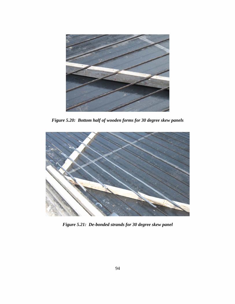
94
Figure 5.20: Bottom half of wooden forms for 30 degree skew panels
Figure 5.21: De-bonded strands for 30 degree skew panel

95
Figure 5.22: Finished rebar cage for 30 degree skew panel prior to formwork completion
Figure 5.23: Flexural reinforcement in 30 degree skew panels

96
Figure 5.24: Clamp attached to strands to brace formwork
Figure 5.25: Two 30 degree skew panels ready for casting

97
5.3.2 Casting
Casting panels in the long lines common in prestressed concrete plants is a very
quick process. A truck carrying several yards of fresh concrete from the on-site batch
plant drove directly up to the casting location. The concrete was placed from the truck
into the casting bed. The laborers then spread the concrete around the panel with shovels
and dragged a vibrating screed across the top to create a level surface. The entire process
took less than 4 minutes for both panels. Approximately 10 minutes later, a broom was
used to create a roughened surface on the panels.
Typically during the casting process at this precast plant, the lines are flooded in
locations where panels are completed to cure the panels. It is possible that flooding may
tend to reduce the surface roughness of a "standard broom finish." The length of time
exposed may also affect the curing process depending on ambient air temperatures.
Figure 5.26: Placing concrete in casting bed

98
Figure 5.27: Leveling concrete with shovels and vibrating screed
Figure 5.28: Casting complete

99
Figure 5.29: Broom finish
5.3.3 Assessment of Panel Construction
Four 30 degree skew panels were produced by a precast concrete plant. The
fabrication processes were observed for two of the panels cast on the same day. The
wooden formwork had already been constructed upon arrival, so the time required for
fabrication is unknown. De-bonding the necessary strands and placing the additional
longitudinal and transverse reinforcement took a matter of minutes. Placing and finishing
the concrete was no different than standard rectangular panels and therefore required no
additional time. Overall, the procedures for producing the trapezoidal panels went
smoothly and quickly. The labor foreman gave the impression that the extra work
required for trapezoidal panels, including custom formwork, de-bonding strands, and
placing additional reinforcement beneath the strands, was not a problem and could be
accomplished on a routine basis.

100
CHAPTER 6
Bridge Deck Construction
6.1 INTRODUCTION
With fabrication of the panels completed, the next phase of the project involved
full-scale testing. Three panels fabricated at Ferguson Laboratory were tested along with
two panels produced by the precast plant. The processes involving the precast panels
used to construct the test specimen are described in this chapter.
6.2 BRIDGE DECK SPECIMENS
Five bridge deck specimens were built and tested. Panel P45F60-2 was not used
in constructing a bridge deck specimen because it was a redundant design and primarily
fabricated to test cracking occurrence at release. The second set of 30 degree skew
panels, P30P45-3 and P30-45-4, will be used for bridge deck test specimens in the future.
All bridge deck specimens were loaded with a single wheel load at the center of
the skewed end. Additionally, the panels containing the parallel strand pattern were
loaded a second time with a single wheel load at the center of the non-skewed end to test
the strength of the partially prestressed panel end. Because the non-skewed end of the
flared strand panel was fully prestressed, a second test was non necessary. To more
accurately simulate field conditions for the non-skewed end tests, an additional 4 ft. by 9
ft. 6 in. rectangular panel was placed adjacent to the skewed panel with the topping slab
placed over both panels. All rectangular panels were cast at a precast plant and delivered
to Ferguson Laboratory. A summary of the bridge deck test specimens is provided in
Table 6.1. The nomenclature used to identify the test specimens is as follows: 1) Positive

101
moment (P), 2) 45 degree (45) or 30 degree (30) skew, 3) Prestressed panels detail (P),
and 4) the specimen number (1-3).
Table 6.1: Summary of bridge deck test specimens
Specimen No. Panel Skew Angle
Adjacent Rectangular Panel
P45P1 P45F60-1 45° No P45P2 P45P60-1 45° Yes P45P3 P45P45-1 45° Yes P30P1 P30P45-1 30° Yes P30P2 P30P45-2 30° Yes
To simulate bridge girders, each panel was supported on 12 in. by 12 in. concrete
beams with a foam bedding strip between the concrete beams and the prestressed panel.
The bedding strip for specimen P45P1 was conventional foam purchased from a
hardware store. The remainder of the specimens used the same 40 psi foam bedding strip
as TxDOT bridge construction. Because bearing conditions were critical, the maximum
bedding strip width allowed by TxDOT of 2 in. was selected. To ensure good concrete
flow beneath the overhanging edge of the panel, the bedding strips were cut 2 in. tall. In
the specimens containing an adjacent rectangular panel, the panels were set with a 3/4 in.
gap between them. Backer rod was then used to seal this gap. A schematic of the
construction process for the bridge deck specimens is shown in Figure 6.1. More detailed
descriptions of the test setups are given in Boswell (2008). In Figure 6.2, a photo of the
construction of specimen P45P3 is shown.

102
Figure 6.1: Schematic of construction of bridge deck test specimens (Boswell 2008)
Figure 6.2: Construction of specimen P45P3
Rectangular Panel
Trapezoidal Panel
Support Beam
Bedding Strip

103
6.3 BEDDING STRIP COMPRESSION
6.3.1 Specimen P45P1
The conventional foam used for specimen P45P1 bedding strip had insufficient
strength. Upon placement of the panel, the bedding strip supporting the short edge of the
panel compressed more than 1.5 in. As a result, temporary supports were placed beneath
the test setup near the short edge of the panel until the concrete topping slab had cured.
The bedding strip on the long edge did not compress appreciably and did not require a
temporary support.
6.3.2 Specimen P45P2
The test setups for specimens P45P2 and P45P3 both consisted of the trapezoidal
panel with a rectangular panel adjacent to the non-skewed end. P45P2 used a trapezoidal
panel with a 60 in. short edge length, which should have had a bearing pressure of 37 psi
under an evenly distributed load. After placement of the topping slab for specimen
P45P2, a large amount of compression in the bedding strip beneath the short edge of the
trapezoidal panel was discovered. Directly under the obtuse-angled corner, the deflection
was 3/4 in. as shown in Figure 6.3. This compression decreased linearly to the non-
skewed end where the compression was approximately 3/8 in. However, beneath the
rectangular panel next to the non-skewed end, the compression was roughly 1/16 in. This
differential settlement, shown in Figure 6.4, indicates a much larger bearing pressure
beneath the short edge of the trapezoidal panel. No noticeable compression was
measured beneath the long edge of the trapezoidal panel.

104
Figure 6.3: Bedding strip compression beneath obtuse corner of specimen P45P2
Figure 6.4: Differential compression in bedding strip at joint between trapezoidal and rectangular panels in specimen P45P2
3/4"
5/16"
1/16"

105
6.3.3 Specimen P45P3
A trapezoidal panel with a 45 in. short edge length was used in specimen P45P3,
which should result in a higher bearing pressure, almost 50 psi, with an evenly distributed
load. However, the bedding strip only compressed approximately 3/8 in. uniformly
across the length of the short edge after the topping slab was cast. The compression of
the bedding strip beneath the obtuse angled corner of specimen P45P3 is shown in Figure
6.5. Similar to construction of the specimen P45P2, there was a differential compression
of 1/4 in. between the non-skewed end of the trapezoidal panel and the adjacent
rectangular panel (Figure 6.4). Compression of the bedding strip supporting the
rectangular panel as well as the long edge of the trapezoidal panel was about at 1/16 in.
on average.
Figure 6.5: Bedding strip compression beneath obtuse corner specimen P45P3
3/8"

106
Figure 6.6: Differential compression in bedding strip at joint between trapezoidal and rectangular panels in specimen P45P3
6.3.4 Specimens P30P1 and P30P2
The 30 degree skew panels were delivered to Ferguson Laboratory on a flatbed
truck. They were transported to their respective test setups with the overhead crane.
Both panels had 45 in. short edge lengths which should produce less than 40 psi bearing
pressure with and evenly distributed load. During construction of the cast-in-place
topping slabs of either P30P1 or P30P2, there was no appreciable compression of the
bedding strip at any location.
6.4 Assessment of Construction of Bridge Deck Specimens
The precast panels were placed on concrete beams with a foam bedding strip
between the concrete beams and the prestressed panels. Formwork was erected along
1/4"

107
with expansion joint armor prior to placing the reinforcing mat and casting the topping
slab. Several observations were made throughout the construction procedures.
Placing both the rectangular and trapezoidal panels required roughly the same
amount of time. Small areas exist where conventional formwork may still be required
along the end of the slab, namely over the girders and between the expansion joint armor
and prestressed panel. Because the expansion joint armor is supported by the girders,
removing the formwork does not affect the armor bearing.
During the construction of all three 45 degree skew bridge deck specimens,
significant compression of the bedding strip was observed beneath the short edge of the
trapezoidal panel. It was also noticed that when the bedding strip compressed, the slab
thickness increased, adding to the weight and bearing pressure on the foam bedding strip.
Upon further investigation, it was discovered that the conventional foam used in
specimen P45P1 had a compressive strength of 25 psi. Due to the magnitude of
compression beneath the short edge of the panel in specimen P45P1, the bearing
pressures substantially exceed 25 psi.
Simple bearing tests conducted on samples of 40 psi bedding strip foam verified
the compressive strength. However, a linear relationship was found between load and
compression which resulted in roughly 1/2 in. compression at a bearing pressure of 40
psi. Once the 40 psi pressure was exceeded, significant compression occurred without
much additional load. Therefore, the bearing pressures beneath the short edge of the
trapezoidal panels in specimens P45P2 may not have exceeded 40 psi. However, the 3/4
in. compression observed beneath the obtuse-angled corner in specimen P45P2 most
likely surpassed 40 psi.
When bedding strip compression was discussed with TxDOT bridge engineers, it
was deemed tolerable as long as the minimum bedding strip requirements were still met.

108
CHAPTER 7
Summary, Conclusions, and Recommendations
7.1 SUMMARY
Prestressed concrete panels have been used by the bridge construction industry in
the state of Texas for many years to increase speed and improve safety and economy.
The panels serve as stay-in-place formwork and become a part of a composite deck after
a topping slab is cast. At expansion joint locations, however, TxDOT currently uses the
IBTS detail rather than prestressed panels. This cast-in-place detail requires temporary
formwork and slows construction processes. Prestressed panels are used at the expansion
joints of 0 degree skew bridge decks in a new detail developed under TxDOT research
project 0-4418. With new detail, a more economical alternative to the current IBTS
detail is provided.
The primary goals of this research project were to evaluate the feasibility of
producing trapezoidal-shaped prestressed concrete panels as well as address construction
related issues so that use of the new panel detail can be extended to include skewed
expansion joints. One research objective was to devise a fabrication method that could
accommodate a wide range of skew angles but maintain the economy of mass production.
Another research objective involved construction of full-scale test specimens with
trapezoidal panels so that any construction related problems could be observed.
A total of eight trapezoidal panels were fabricated using two primary prestressing
layouts. Four were produced in Ferguson Laboratory and four were produced at a precast
plant. A flared prestressing pattern with a 45 degree skew angle and a 60 in. short edge
length were used in panel P45F60-1. Additional hairpin bursting reinforcement was also

109
included in P45F60-1 and the strands were released when the concrete reached a 5,000
psi compressive strength. The same geometry and prestressing pattern from P45F60-1
was used in panel P45F60-2, but the additional bursting reinforcement was removed and
the compressive strength of concrete at release was reduced to 4,000 psi. The same
geometry with a 45 degree skew angle and 60 in. short edge length was continued in
panel P45P60-1, but a parallel strand pattern with the strands parallel to the skewed end
of the panel was used. Additionally, mild reinforcing bars were placed parallel to the
non-skewed end of the panel. The parallel prestressing pattern and 45 degree skew angle
were maintained in panel P45P45-1, but the short edge length was reduced to 45 in. Mild
reinforcing bars were also placed parallel to the non-skewed panel end. The parallel
prestressing strand pattern was used in panels P30P45-1, 2, 3 and 4 with a 30 degree
skew and 45 in. short edge length. Mild reinforcing bars placed parallel to the non-skew
end were also used. All panels were 4 in. thick and 9 ft. 6 in. wide.
Five of the eight panels were used for single bay, full-scale bridge deck test
specimens. In four of the bridge deck test specimens, an additional rectangular panel
produced at a precast plant was placed adjacent to the non-skewed end of the panel. Each
panel was set onto bedding strips glued to concrete beams before a mat of deck
reinforcing steel was tied and topping slab placed.
7.2 CONCLUSIONS
Based on the experiences and observations during production of the trapezoidal
panels, the construction of full-scale test specimens, and discussions with TxDOT Bridge
Division representatives, the following conclusions can be drawn regarding the
practicality and constructibility of trapezoidal prestressed panels.
• Flared Prestressing Pattern
o Custom formwork is required for each different panel geometry.

110
o The spacing of prestressing strands would be different for each
combination of skew angle and panel width. This would require
casting beds to be capable of shifting bearing locations to
accommodate variations in strand spacing. Moreover, since each
strand layout is unique to the panel geometry, standard drawings could
not be utilized.
o Non-parallel prestressing strands create awkward bearing conditions,
particularly on the short edge of the panel where strands converge on
one another after exiting the face of the panel.
o No cracking was observed in highly stressed regions after strand
release at the TxDOT specified release strength for panels of 4,000 psi
despite lack of bursting reinforcement.
o Trapezoidal panels using a flared prestressing pattern cannot be mass
produced on a long-line casting bed.
• Parallel Prestressing Pattern
o Custom formwork is required for each different panel geometry.
o Placing reinforcing bars beneath the prestressing strands is simple and
requires minimal time.
o Standard bulkheads could be used since strand spacing remains
constant for all panel geometries.
o Standard spacing of prestressing strands parallel to the skewed end
allows implementation to any panel geometry.
o Due to lack of required development length, some strands may require
de-bonding or omission, which creates a region with partially
prestressed concrete.

111
o No cracking was observed at interface of prestressed and non-
prestressed regions where strands were de-bonded or omitted.
o Trapezoidal panels using a parallel prestressing strand pattern can be
mass produced on a long-line casting bed. However, panels with large
widths and skew angles would require casting beds wider than the 8 ft.
standard to be built.
• Construction
o Setting trapezoidal panels on support beams and aligning the skewed
end is not difficult.
o Compression of the bedding strip under high bearing pressures is not a
concern to TxDOT engineers as long as minimum clearance
requirements are still met.
o The expansion joint armor is supported on the girders; therefore,
removal of conventional formwork does not affect the placement of
the armor.
o Minimal formwork would still be required at the ends of the girders
and between the expansion joint armor and precast panel.
o Panel fit-up errors require a standard solution. One potential solution
is custom cutting panels on site with a concrete saw.
7.3 RECOMMENDATIONS
The results of the research project demonstrate that producing trapezoidal
prestressed panels can be economical while accommodating a wide range of geometries.
Due to the complexity of the flared prestressing bearings, the variability of strand
spacing, and the inability to use a long-line casting bed, the parallel prestressing pattern is
the suggested design alternative. The parallel prestressing strand pattern allows current

112
fabrication techniques and procedures to be utilized thereby maintaining the efficiency of
the precast industry.
The research project also showed that trapezoidal prestressed panels can be used
as stay-in-place formwork at skewed expansion joints. The compression in the bedding
strip was deemed acceptable when using a 45 degree, 9 ft. 6 in. wide panel with a 45 in.
short edge length and 40 psi bedding strip. Further research is needed to determine
minimum bearing lengths for smaller panels and/or stronger bedding strip. Other
construction issues, such as panel fit-up and formwork over the girders, should be
discussed with bridge construction contractors to determine capabilities and solutions.

113
References
ACI Committee 318. "Building Code Requirements for Reinforced Concrete." ACI Standard 318-08. American Concrete Institute, Detroit, Michigan, 2008.
Abendroth, R., Pratanata, H., and Singh, B., (1991) "Composite Precast Prestressed Concrete Bridge Slabs," Iowa Department of Transportation Report HR-310, Iowa State University, August, 194 pp.
Agnew, L. (2007), "Evaluation of the Fatigue Behavior of Bridge Decks with Precast Panels at Expansion Joints," Master's Thesis, The University of Texas at Austin, May, 152 pp.
American Association of State Highway and Transportation Officials (2004), AASHTO LRFD Bridge Design Specifications, 3rd Edition.
Coselli, C. (2004) "Behavior of Bridge Decks with Precast Panels at Expansion Joint," Master's Thesis, The University of Texas at Austin, May, 286 pp.
Griffith, E. (2003), "Behavior of Bridge Slab Ends at Expansion Joints," Master's Thesis, The University of Texas at Austin, December, 284 pp.
Merrill, Brian D. 2002. Texas' Use of Precast Concrete Stay-In-Place Forms for Bridge Decks. 2002 Concrete Bridge Conference.
Rajagopalan, N. Bridge Superstructure. Oxford, U.K.: Alpha Science International Ltd., 2006.
Ryan, J. (2003), "Behavior of Bridge Slab Ends at Expansion Joints," Master's Thesis, The University of Texas at Austin, August, 253 pp.
Texas Department of Transportation, "Standard Detail Drawings" Retrieved Septmeber 28, 2006 from http://www.dot.state.tx.us/insdtdot/orgchart/cmd/cserve/standard/bridge-e.htm
Van Landuyt, Dean, "Survey of Skew Angles of TxDOT Bridges," Results presented at research project meeting, Austin, Texas, September 2006.

114
Vita
Alan Renison Kreisa, the son of Barry Kreisa and Beverly Kee, was born in
Richmond, Virginia on February 27, 1982. He graduated from Douglas Southall
Freeman High School in June, 2000 and enrolled at The University of Virginia where he
received a Bachelor of Science in Civil Engineering in May 2004. From July 2004 to
June 2006, he worked in the Bridge Design group for URS Corporation in Hunt Valley,
Maryland. He wed Emily Jane Snyder of Asheville, North Carolina in June 2006, and in
August 2006, he enrolled in graduate school at The University of Texas at Austin. Upon
graduation he and his wife will be moving to Denver, CO where he will begin working
for Summit Engineering, Inc.
Permanent address: 1787 S. Logan St.
Denver, CO 80210
This thesis was typed by the author.