Copyright 2008 Koren ECE666/Koren Part.5c.1 Israel Koren Spring 2008 UNIVERSITY OF MASSACHUSETTS...
38
Copyright 2008 Koren ECE666/Koren Part.5c.1 Israel Koren Spring 2008 UNIVERSITY OF MASSACHUSETTS Dept. of Electrical & Computer Engineering Digital Computer Arithmetic ECE 666 Part 5c Fast Addition - III
-
Upload
frances-branscomb -
Category
Documents
-
view
217 -
download
0
Transcript of Copyright 2008 Koren ECE666/Koren Part.5c.1 Israel Koren Spring 2008 UNIVERSITY OF MASSACHUSETTS...

Copyright 2008 Koren ECE666/Koren Part.5c.1
Israel Koren
Spring 2008
UNIVERSITY OF MASSACHUSETTS Dept. of Electrical & Computer
Engineering
Digital Computer Arithmetic ECE 666
Part 5c Fast Addition - III

Copyright 2008 Koren ECE666/Koren Part.5c.2
Hybrid Adders Combination of two or more addition methods Common approach: one method for carry -
another for sum Two hybrid adders combining variation of a
carry-select for sum and modified Manchester for carry Both divide operands into equal groups - 8 bits each First - uses carry-select for sum for each group of 8 bits
separately Second - uses a variant of conditional-sum
Group carry-in signal that selects one out of two sets of sum bits not generated in ripple-carry
Instead, carries into 8-bit groups generated by a carry-look-ahead tree
64-bit adder - carries are c8,c16,c24,c32,c40,c48,c56

Copyright 2008 Koren ECE666/Koren Part.5c.3
Blocking Factor in Carry Tree Structure of carry-look-ahead tree for
generating carries similar to those seen before
Differences - variations in blocking factor at each level and exact implementation of fundamental carry operator
Restricting to a fixed blocking factor - natural choices include 2, 4 or 8 2 - largest number of levels in tree, vs. 8 - complex modules for fundamental carry operator
with high delay
Factor of 4 - a reasonable compromise A Manchester carry propagate/generate
module (MCC) with a blocking factor of 4

Copyright 2008 Koren ECE666/Koren Part.5c.4
64-bit Hybrid Adder

Copyright 2008 Koren ECE666/Koren Part.5c.5
Manchester Carry Module

Copyright 2008 Koren ECE666/Koren Part.5c.6
MCC - General Case MCC accepts 4 pairs of inputs: (Pi1:i0,Gi1:i0),(Pj1:j0,Gj1:j0),(Pk1:k0,Gk1:k0),(Pl1:l0,Gl1:l0) where i1 i0, j1 j0, k1 k0, l1 l0 Produces 3 pairs of outputs: (Pj1:i0,Gj1:i0),(Pk1:i0,Gk1:i0),(Pl1:i0,Gl1:i0) where i1 j0-1, j1 k0-1, k1 l0-1 Allows overlap among input subgroups

Copyright 2008 Koren ECE666/Koren Part.5c.7
Carry Tree
First level - 14 MCCs calculating (P3:0,G3:0),(P7:4,G7:4),…,(P55:52,G55:52) only outputs P3:0 and G3:0 are utilized
Second level: each MCC generates 2 pairs (P3:0, G3:0),(P1:0, G1:0)
Providing (P7:0,G7:0),(P15:0,G15:0), (P23:16,G23:16),(P31:16,G31:16), (P39:32,G39:32),(P47:32,G47:32), (P55:48,G55:48)
Generates c8 & c16 - G7:0 & G15:0
c0 is incorporated into (P3:0, G3:0)

Copyright 2008 Koren ECE666/Koren Part.5c.8
Third level - Two MCCs Sufficient One for dashed box generating c24, c32 and c40
Second MCC for 2 remaining outputs with inputs 55:48, 47:32, 31:16 and 15:0 generating c48 and c56
MCC in dashed box must implement 2 dotted lines from 23:16 - required for generating 23:0
Above implementation of adder not unique does not necessarily minimize overall execution time
Alternate implementations: variable size of carry-select groups and of MCCs at different levels of tree

Copyright 2008 Koren ECE666/Koren Part.5c.9
A Schematic Diagram of a 32-bit Hybrid Adder

Copyright 2008 Koren ECE666/Koren Part.5c.10
Grouping of Bits in a 64-bit Adder
64 bits divided into two sets of 32 bits, each set further divided into 4 groups of 8 bits
For every group of 8 bits - 2 sets of conditional sum outputs generated separately
Two most significant groups combined into group of size 16
Further combined with next group of 8 to form group of 24 bits and so on principle of conditional-sum addition However, the way input carries for basic 8-bit groups
are generated is different
MCC generates Pm, Gm and Km and cout ,cout for assumed incoming carries of 0 and 1
Conditional carry-out signals control multiplexers
0 1

Copyright 2008 Koren ECE666/Koren Part.5c.11
Dual and Regular Multiplexer
Two sets of dual multiplexers (of size 8 and 16)
Single regular multiplexer of size 24

Copyright 2008 Koren ECE666/Koren Part.5c.12
High-Order Half of 64-bit Adder
Similar structure but incoming carry c32 calculated by separate carry-look-ahead circuit
Inputs are conditional carry-out signals generated by 4 MCCs
Allows operation of high-order half to overlap operation of low-order half
Summary: combines variants of 3 different techniques for fast addition: Manchester carry generation, carry-select, conditional-sum
Other designs of hybrid adders exist - e.g., groups with unequal number of bits
“Optimality” of hybrid adders depends on technology and delay parameters

Copyright 2008 Koren ECE666/Koren Part.5c.13
Carry-Save Adders (CSAs) 3 or more operands added simultaneously (e.g., in
multiplication) using 2-operand adders Time-consuming carry-propagation must be
repeated several times: k operands - k-1 propagations
Techniques for lowering this penalty exist - most commonly used - carry-save addition
Carry propagates only in last step - other steps generate partial sum and sequence of carries
Basic CSA accepts 3 n-bit operands; generates 2 n-bit results: n-bit partial sum, n-bit carry
Second CSA accepts the 2 sequences and another input operand, generates new partial sum and carry
CSA reduces number of operands to be added from 3 to 2 without carry propagation

Copyright 2008 Koren ECE666/Koren Part.5c.14
Implementing Carry Save Adders
Simplest implementation - full adder (FA) with 3 inputs x,y,z
x+y+z=2c+s (s,c - sum and carry outputs)
Outputs - weighted binary representation of number of 1's in inputs
FA called a (3,2) counter n-bit CSA: n (3,2) counters
in parallel with no carry links

Copyright 2008 Koren ECE666/Koren Part.5c.15
Carry-Save Adder for four 4-bit Operands
Upper 2 levels - 4-bit CSAs 3rd level - 4-bit carry-propagating adder (CPA) Ripple-carry adder - can be replaced by a carry-
look-ahead adder or any other fast CPA Partial sum bits and carry bits interconnected to
guarantee that only bits having same weight are added by any (3,2) counter

Copyright 2008 Koren ECE666/Koren Part.5c.16
Adding k Operands
(k-2) CSAs + one CPA If CSAs arranged in cascade
- time to add k operands is (k-2)TCSA + TCPA
TCPA ; TCSA - operation time of CPA ; CSA G ; FA delay of a single gate ; full adder TCSA = FA 2 G
Sum of k operands of size n bits each can be as large as k(2 -1)
Final addition result may reach a length of n+log 2 k bits
n
Copyright 2008 Koren ECE666/Koren Part.5c.17
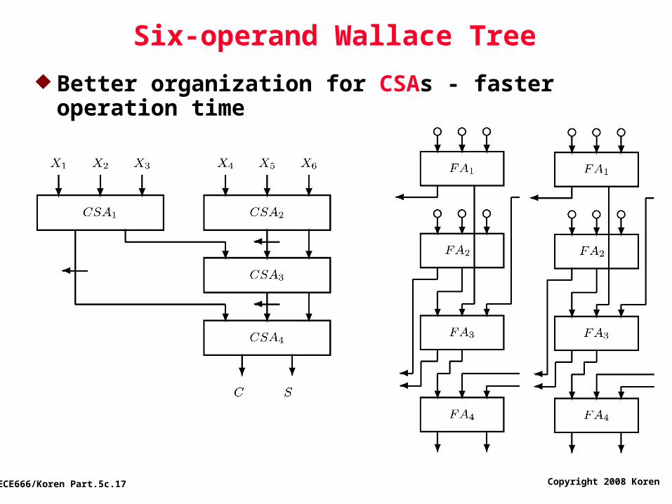
Six-operand Wallace Tree
Better organization for CSAs - faster operation time

Copyright 2008 Koren ECE666/Koren Part.5c.18
Number of Levels in Wallace Tree
Number of operands reduced by a factor of 2/3 at each level - (l - number of levels)
Consequently, l = Only an estimate of l - number of operands at
each level must be an integer Ni - number of operands at level i Ni+1 - at most 3/2 Ni ( x - largest integer
smaller than or equal to x ) Bottom level (0) has 2 - maximum at level 1 is
3 - maximum at level 2 is 9/2 =4 Resulting sequence: 2,3,4,6,9,13,19,28,… For 5 operands - still 3 levels

Copyright 2008 Koren ECE666/Koren Part.5c.19
Number of Levels in a CSA Tree for k operands
Example: k=12 - 5 levels - delay of 5TCSA instead of 10TCSA in a linear cascade of 10 CSAs

Copyright 2008 Koren ECE666/Koren Part.5c.20
Most Economical Implementation (Fewer CSAs)
Achieved when number of operands is element of 3,4,6,9,13,19,28,…
If given number of operands, k, not in sequence - use only enough CSAs to reduce k to closest (smaller than k) element
Example: k=27, use 8 CSAs (24 inputs) rather than 9, in top level - number of operands in next level is 82+3=19
Remaining part of tree will follow the series

Copyright 2008 Koren ECE666/Koren Part.5c.21
(7,3) and Other Counters
(7,3) counter: 3 outputs - represent number of 1's in 7 inputs
Another example: (15,4) counter
In general: (k,m) counter - k and m satisfy 2 -1 k or m log 2 (k+1)
(7,3) counter using (3,2) counters:
Requires 4 (3,2)’s in 3 levels - no speed-up
m

Copyright 2008 Koren ECE666/Koren Part.5c.22
(7,3) Counters
(7,3) can be implemented as a multilevel circuit - may have smaller delay
Number of interconnections affects silicon area - (7,3) preferrable to (3,2) (7,3) has 10 connections and removes 4 bits (3,2) has 5 connections and removes only 1 bit
Another implementation of (7,3) - ROM of size 2 x 3= 128 x 3 bits
Access time of ROM unlikely to be small enough
Speed-up may be achieved for ROM implementation of (k,m) counter with higher values of k
7

Copyright 2008 Koren ECE666/Koren Part.5c.23
Avoiding Second Level of Counters
Several (7,3) counters (in parallel) are used to add 7 operands - 3 results obtained
Second level of (3,2) counters needed to reduce the 3 to 2 results (sum and carry) added by a CPA
Similarly - when (15,4) or more complex counters are used - more than two results generated
In some cases - additional level of counters can be combined with first level - more convenient implementation
When combining a (7,3) counter with a (3,2) counter - combined counter called a (7;2) compressor

Copyright 2008 Koren ECE666/Koren Part.5c.24
(k;m) Compressor
Variant of a counter with k primary inputs, all of weight 2 , and m primary outputs of weights 2 ,2 ,...,2
Compressor has several incoming carries of weight 2 from previous compressors, and several outgoing carries of weights 2 and up
Trivial example of a (6;2) compressor: All outgoing carries have weight 2
Number of outgoing carries =
number of incoming carries = k-3 (in general)
i
i+1i
i+1
i+1
i
i+m-1

Copyright 2008 Koren ECE666/Koren Part.5c.25
Implementation of a (7;2) Compressor
7 primary inputs of weight 2 and 2 carry inputs from columns i-1 and i-2
2 primary outputs, S2 and S2 , and 2 outgoing carries C2 , C2 , to columns i+1 and i+2
Input carries do not participate in generation of output carries - avoids slow carry-propagation
Not a (9,4) counter - 2 outputs with same weight Above implementation does not offer any speedup Multilevel implementation may yield smaller delay as long
as outgoing carries remain independent of incoming carries
Bottom right (3,2) - additional (3,2), while remaining four - ordinary (7,3) counter
i
i
i+1
i+1 i+2

Copyright 2008 Koren ECE666/Koren Part.5c.26
Multiple-column counters
Generalized parallel counter: add l input columns and produce m-bit output - (kl-1,kl-
2,...,k0,m) ki - number of input bits in i-th column
with weight 2 (k,m) counter - a special case Number of outputs m must satisfy
If all l columns have same height k - (k0=k1= ... =kl-1=k) -
2 - 1 k(2 - 1)
i
m l

Copyright 2008 Koren ECE666/Koren Part.5c.27
Example - (5,5,4) Counter k=5,l =2,m=4 2 -1=k(2 -1) - all
16 combinations of output bits are useful
(5,5,4) counters can be used to reduce 5 operands (of any length) to 2 results that can then be added with one CPA
Length of operands determines number of (5,5,4) counters in parallel
Reasonable implementation - using ROMs For (5,5,4) - 2 x4 (=1024x4) ROM
m l
5+5

Copyright 2008 Koren ECE666/Koren Part.5c.28
Number of Results of General Counters
String of (k,k,…,k,m) counters may generate more than 2 intermediate results requiring additional reduction before CPA
Number of intermediate results: A set of (k,k,…,k,m) counters, with l
columns each, produces m-bit outputs at intervals of l bits
Any column has at most m/l output bits k operands can be reduced to s= m/l
operands If s=2 - a single CPA can generate final sum
Otherwise, reduction from s to 2 needed

Copyright 2008 Koren ECE666/Koren Part.5c.29
Example
Number of bits per column in a 2-column counter (k,k,m) is increased beyond 5 - m 5 and s= m/2 > 2
For k=7, 2 -1 7 x 3 = 21 m=5 (7,7,5) counters generate s=3 operands -
another set of (3,2) counters is needed to reduce number of operands to 2
m

Copyright 2008 Koren ECE666/Koren Part.5c.30
Reducing Hardware Complexity of CSA Tree Design a smaller carry-save tree - use it iteratively
n operands divided into n/j groups of j operands - design a tree for j+2 operands and a CPA
Feedback paths - must complete first pass through CSA tree before second set of j operands is applied
Execution slowed down - pipelining not possible

Copyright 2008 Koren ECE666/Koren Part.5c.31
Pipelining of Arithmetic Operations
Pipelining - well known technique for accelerating execution of successive identical operations
Circuit partitioned into several subcircuits that can operate independently on consecutive sets of operands
Executions of several successive operations overlap - results produced at higher rate
Algorithm divided into several steps - a suitable circuit designed for each step
Pipeline stages operate independently on different sets of operands
Storage elements - latches - added between adjacent stages - when a stage works on one set of operands, preceding stage can work on next set of operands

Copyright 2008 Koren ECE666/Koren Part.5c.32
Pipelining - Example
Addition of 2 operands X,Y performed in 3 steps
Latches between stages 1 and 2 store intermediate results of step 1
Used by stage 2 to execute step 2 of algorithm Stage 1 starts executing step 1 on next set of
operands X,Y

Copyright 2008 Koren ECE666/Koren Part.5c.33
Pipelining Timing Diagram
4 successive additions with operands X1 & Y1, X2 & Y2, X3 & Y3, X4 & Y4 producing results Z1, Z2, Z3, Z4

Copyright 2008 Koren ECE666/Koren Part.5c.34
Pipeline Ratei - execution time of stage i
l - time needed to store new data into latch Delays of different stages not identical - faster
stages wait for slowest before switching to next task
- time interval between two successive results being produced by pipeline:
k - number of stages
- pipeline period ; 1/ - pipeline rate or bandwidth
Clock period After latency of 3, new results produced at rate
1/

Copyright 2008 Koren ECE666/Koren Part.5c.35
Design Decisions Partitioning of given algorithm into steps to be
executed by separate stages Steps should have similar execution times - pipeline
rate determined by slowest step
Number of steps As this number increases, pipeline period decreases,
but number of latches (implementation cost) and latency go up
Latency - time elapsed until first result produced Especially important when only a single pass through
pipeline required
Tradeoff between latency and implementation cost on one hand and pipeline rate on the other hand
Extra delay due to latches, l , can be lowered by using special circuits like Earl latch

Copyright 2008 Koren ECE666/Koren Part.5c.36
Pipelining of Two-Operand Adders
Two-operand adders - usually not pipelined Pipelining justified with many successive additions Conditional-sum adder - easily pipelined
log2n stages corresponding to log2n steps - execution of up to log2n additions can be overlapped
Required number of latches may be excessive Combining several steps to one stage reduces
latches' overhead and latency Carry-look-ahead adder cannot be pipelined -
some carry signals must propagate backward Different designs can be pipelined - final carries
and carry-propagate signals (implemented as Pi=xiyi) used to calculate sum bits - no need for feedback connections

Copyright 2008 Koren ECE666/Koren Part.5c.37
Pipelining in Multiple-Operand Adders
Pipelining more beneficial in multiple-operand adders like carry-save adders
Modifying implementation of CSA trees to form a pipeline is straightforward - requires only addition of latches
Can be added at each level of tree if maximum bandwidth is desired
Or - two (or more) levels of tree can be combined to form a single stage, reducing overall number of latches and pipeline latency

Copyright 2008 Koren ECE666/Koren Part.5c.38
Partial Tree Reduced hardware complexity of
CSA tree - partial tree Two feedback connections prevent
pipelining Modification - intermediate
results of CSA tree connected to bottom level of tree
Smaller tree with j inputs, 2 separate CSAs, and a set of latches at the bottom
CSAs and latches form a pipeline stage
Top CSA tree for j operands can be pipelined too - overall time reduced