Copyright © 2007 Nissan Marine Co. Ltd....This operator’s manual contains information on the...
143
D l@IJ OWNER'S OPERATING MANUAL
Transcript of Copyright © 2007 Nissan Marine Co. Ltd....This operator’s manual contains information on the...
D
l@IJ OWNER'S OPERATING MANUAL

Copyright © 2007 Nissan Marine Co. Ltd. All rights reserved. No part of this manual may be reproduced or transmitted in any form or by any means without the express written permission of Nissan Marine Co., Ltd.


IMPORTANT
DANGER/WARNING/CAUTION/NOTE Before operating your outboard motor, be sure to thoroughly read and understand this Owner’s Manual and follow all of the mstructions shown. Of particular importance is information preceded by the words “DANGER,” “WARNING,” ” CAUTION,” and “NOTE.” Always pay special attention to such information to ensure safer and trouble-free operation at all times.
AAA DANGER Failure to observe it may result in severe personal injury or death to the operator and passengers.
AA WARNING Failure to observe this instruction could result in personal injury to the operator, passengers and bystanders.
A CAUTION This instruction sets out special procedures or precautions that must be followed to avoid damages to the outboard.
1 NOTE
This instruction provides special information to facilitate the use or maintenance of the outboard or to clarify important points.
2

NISSAN NSGOBaNS70B
PREFACE
Thank you very much for selecting a Nissan
Marine Outboard Motor.
This operator’s manual contains information
on the operating procedures, preventive main-
tenance and inspection procedures of the
Nissan Marine Outboard Motor Model
NS60B. NS70B.
Please read this manual thoroughly before
operating your Nissan outboard motor. You
should become familiar with correct operating
procedures so as to assure many years of safe
and pleasant boating.
0 1992 NISSAN MOTOR CO., LTD. Printed in Japan
1
CONTENTS
1. IMPORTANT NOTICE TO OWNERS
AND OPERATORS ................................... .6
2. SpE=lFlCAT]ONS ....................................... 11
3. NOMENCLATURE ...................................... .14
‘, . INSTALLATION ........................................ -22
1 Installing the Outboard ...................................... .22
2 Installing the Remote Control Device ......................... ..2 5
3 Installing the Co,-& and Leads ................................ -32
4 Installing the Meters. ...................................... ..3 3
SInstallingtheDragLinkAssembly .-.........-.................3 5
6 Installing the Bat@, ....................................... .‘,7
7 Removing the Battery ....................................... 38
8 Installing the steering handle and main switch box
(EF/EFO/EFq ........................................... .39
9 Installing the Propeller. .................................... ..4 0
5. ,=,,,=L AND ENGINE O,L ................................ 45
1NonAuto-mixingModels(EF). .............................. .46
2 Auto-mixing Models (EFO/EFTO/EPOIEPTO) .................. ‘47
6. PRECAUTIONS BEFORE BOATING ............. .-----51
7, RUNNING-IN ............................................ .53
, procedure for Running-~n ................................... .5x
2FuelMixingRatioduringRunning-In~....~~~~..--...~~~~~....--5 4
6. OPERATION ............................................ .55
1 Starting theEngine ........................................ ..5 5
3

2 Emergency Start Procedure ........ ....................... ...6 6
~Warm.“p................................................7 1
4 Warning Systems ........................................ -72
5 Forward/Reverse Running (EF/EFO/EFTO) .................... ‘74
6ShallowWaterRunning(EPTO/EFTO) ...........-............7 8
7 Stopping the Engine. ............ ........................ ...7 9
8 Fuel Spill Prevention ....................................... 82
9. TR,M ADJUSTMENT .................................. .83
10. MOORING AND TRAlLERlNG-.~~~..-~~~~..~~~~....~~~s 9
1 Mooring with the Motor Tilted up. ........................... .89
2MooringorDockingwithTwinOutboards~~.-~~~~..~~~~....~~~~9 5
3 Trail&g ............................................ ..g 5
4 Tilt Stopper Opemtion ........................ ............ .97
11. DISMOUNTING THE ENGINE FROM THE BOAT.....9 9
12. ADJUSTMENTS ...................................... ,101
I Remote Control Lever Movement (EPO/EPTO) ................. 101
2 Tern Tab Adjustment ..................................... ,101
3 Steering Movement Adjustment (EF/EFO) .................. ,102
4 Throttle Grip Movement Adjustment (EF/EFO/EflO) ........... ,103
13. INSPECTION AND MAlNTENANCE..~~..-~~~~~..~.~~10 4
1 Daily Inspection Checklist ...... ................. . ........ ..lO 4
2 periodic Inspection Checklist ................. .......... ... 105
3FlushingtheEnginewithFreshWater.~~....~~~..~.~~....~~~~~10 8
4 Replacing the Propeller ................................ ..llO
4

5 Replacing the Spark plugs ................................. .I1 1
6CheckingandReplacingtheGearOil~~~~ ~~-.~~~~~~.---~~~~~~~lI 4
7 Fuel Line and Filters ...................................... 116
8 Checking and Refilling Oil in the Power Trim &Tilt Unit ......... I18
14. W,NTER STORAGE.. ................................. ,20
1 Engine ............................................... ..,2 0
2Battery.. ............................................. ..~* .
3 Electric Sheer Motor. ................................. . ..121
15. pRE-SE*SON CHECK.. .......................... . ..122
16. IF THE ENGINE IS SUBMERGED IN WATER .... . ..I24
17. -,-ROUBLES,,OOTlNG ............................ . ..I25
,& ACCESSORIES LIST ............................. ..,I28
19. PROPELLER SELECTION TABLE ............... ..-I29
20. OPTIONAL ACCESSORIES ...................... ---I30
21. ASBESTOS PRECAUTIONS. ..................... . ..I32
22. WIRING DIAGRAMS .............................. --,134
5

1. IMPORTANT NOTICE TO OWNERS AND OPERATORS
RUNNING-IN YOUR OUTBOARD MOTOR
The most critical time in the life of your engine is the first 10 hours of operation. Correct operation during this running-in period is of great importance prolonging the life of the engine and ensuring optimum pelformance.
Before operating the outboard. carefully read the RUNNING-IN section of this Manual and be sure to follow the instructions provided
AA WARNING To avoid accidents or injuries resulting from improper use of your
outboard be sure to observe the ‘following important safety
precautions:
* Before using your outboard for the first time, thoroughly read this
Owner’s Manual and make sure that you are familiar with the
features, safety requirements, and maintenance procedures for the
outboard.
*Perform a daily inspection before each use of your outboard,
according to the Daily Inspection Checklist in the INSPECTION
AND MAINTENANCE section.
*Operate your boat at slow and medium speeds in the beginning
until you become fully accustomed to the operating and handling
characteristics with your new outboard motor. Do not operate the outboard at full throttle until you are thoroughly familiar with its
handling.
*Always check that you have the necessary emergency equipment
including the standard spare parts and tools and spare propeller if
necessary on board.
6

AA WARNING *Before boating, give your passengers full instructions about
emergency procedures including the basics of operating the
outboard, how to use the emergency equipment. and what actions
to be taken in the event of trouble.
* Never fail to ensure that both you and all of your passengers are
wearing life jackets when on board.
* Do not operate your outboard while under the influence of alcohol
or drugs, nor allow anyone else to do so.
*At the time of loading your boat, make sure that the weight of both
passengers and goods is evenly distributed between the bow and
stern as well as between the port and starboard sides.
* Follow the procedures shown in the Periodic Inspection section.
Consult with your dealer if necessary
* Do not make any modifications to your outboard or remove any
original equipment, as this may render it unsafe.
* Become familiar with and follow the navigation rules of the areas
where you will operate your boat.
* Before boating, always check the weather forecast to avoid being
caught in bad weather.
NOTE
We strongly recommend that you use only genuine replacement parts and accessories, since any damage caused by the use of parts or accessories other than genuine replacement parts and accessories will not be covered under the warranty.
7
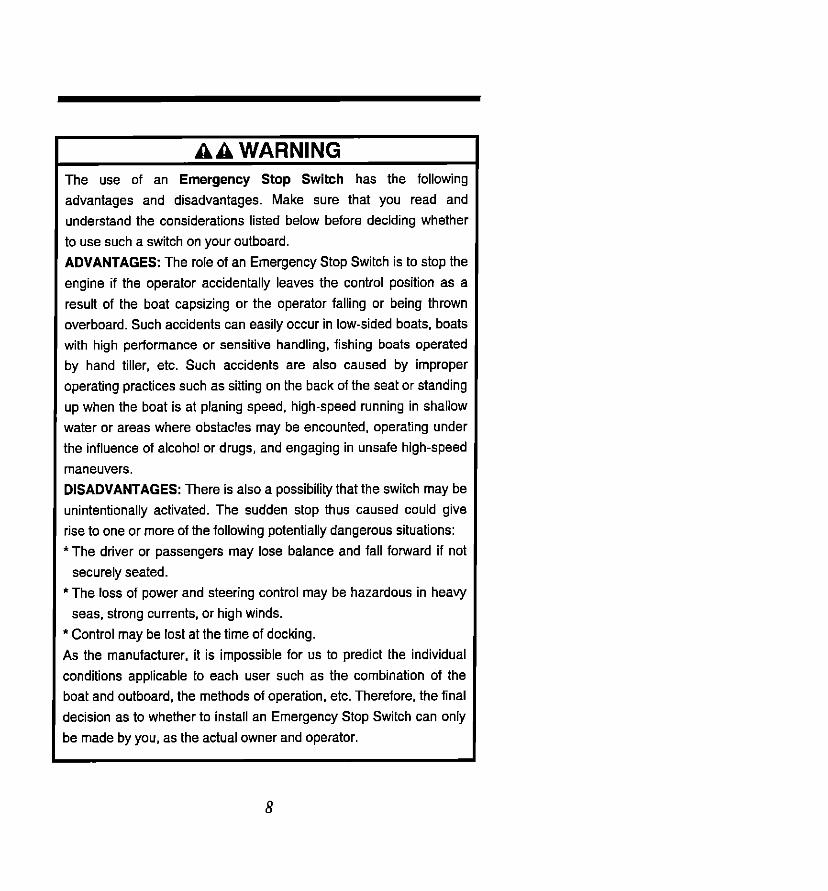
AA WARNING The use of an Emergency Stop Switch has the following
advantages and disadvantages. Make sure that you read and
understand the considerations listed below before deciding whether
to use such a switch on your outboard.
ADVANTAGES: The role of an Emergency Stop Switch is to stop the
engine if the operator accidentally leaves the control position as a
result of the boat capsizing or the operator falling or being thrown
overboard. Such accidents can easily occur in low-sided boats, boats
with high performance or sensitive handling, fishing boats operated
by hand tiller, etc. Such accidents are also caused by improper
operating practices such as sitling on the back of the seat or standing
up when the boat is at planing speed, high-speed running in shallow
water or areas where obstacles may be encounted, operating under
the influence of alcohol or drugs, and engaging in unsafe high-speed
maneuvers.
DISADVANTAGES: There is also a possibility that the switch may be
unintentionally activated. The sudden stop thus caused could give
rise to one or more of the following potentially dangerous situations:
li The driver or passengers may lose balance and fall forward if not
securely seated.
‘The loss of power and steering control may be hazardous in heavy
seas, strong currents, or high winds.
1 Control may be lost at the time of docking.
4s the manufacturer, it is impossible for us to predict the individual
zonditions applicable to each user such as the combination of the
Doat and outboard, the methods of operation, etc. Therefore, the final
decision as to whether to install an Emergency Stop Switch can only
,e made by you, as the actual owner and operator.
8

AA WARNING It is very difficult for a person standing or swimming in the water to
take evasive action should he/she see a power boat heading in
his/her direction, even at a slow speed. Therefore, it is strongly
recommended that when your boat is in the immediate vicinity of
people in the water, the engine be shifted to “NEUTRAL” and shut off.
SERIOUS INJURY IS LIKELY TO OCCUR IF CONTACT IS MADE
WITH A PERSON IN THE WATER BY A MOVING BOAT, GEAR
CASE, PROPELLER, OR ANY SOLID DEVICE AlTACHED TO A
BOAT OR OUTBOARD.
9

Symbols
1
2
Warning, fire risk
Warning, electrical hazard
3 I I \ Choke
4 4r
a Throttle
5 @I
Refer to Owner’s Manual
6 Fuel
7 Engine oil
6
9
Engine start
Engine stop
10 t-l) Clutch
10

uqdo :*
(99’2 x 16’2) LZL x PL @I() lull ‘EopJlS g alog
(Z’LS) 9E6 Q!b3
'iuaumelds!a UOIS!~
E sIapug&J ,o ‘ON
009’S-006% :BOLSN 009’5-006% :fl09SN udr
a6uetl paads WOJU IIW
(OL) 6P’ 15 :EOLSN (09) E 1’PP :809SN kd) MY ‘Wmo ‘WI
(WSZ) LS9 :1x (woz) OES :1 (U!) WW ‘lL,6!+, UOSUEll
(o-912) (SEW) (O’LZZ) ~e’zzz) I’N Wosd (LZ 11) W6001) (B’BBB)
o I, wddv ~6 ‘xaddv s,, ‘xo,ddv co, ‘xaddv 10, ‘xo,ddv 64 ‘W6!=M
(L’SS) SLP’ L ‘xoJddv (U!) UU ‘lL,fi!E# ,,ElCMO
(Z’PL) 09E ‘xolddv (u!) Wu ‘WP!M IleJeAO
(E’BZ) OZL ‘wolddv (~‘0s) oez’ L .xoJddv @I() UILU ‘qlhlal ,,emvJ
EOLSN BOLSN BOLSN EOLSN BOLSN 809SN 809SN 809SN 809SN 809SN =ueN F’PW
Old3 Od3 01zEl* 033 j3* adQ
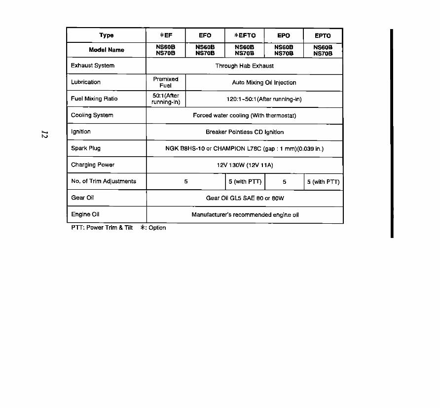
TYpe
Model Name
*EF
I harum
EFO *EFTO EPO EPTO I
NS608 NS6OB NS608 NS608 NSSOB .1”-.^1 NS708 NS7OB NS70B NS708
I Exhaust System Through Hab Exhaust
1 Lubrication Auto Mixing Oil Injection
Fuel Mixing Ratio
Cooling System
5O:l (After running-in)
12O:i -5O:l (After running-in)
Forced water cooling (With thermostat)
Breaker Pointless CD Ignition
Spark Plug
Charging Power
No. of Trim Adjustments
NGK BBHS-10 or CHAMPION L76C (gap : 1 mm)(0.039 in.)
1%‘130W(12V11A)
5 5 (with PlT) 5 5 (with PTT)
Gear Oil GL5 SAE 60 or BOW
Engine Oil Manufacturer’s recommended engine oil
Pm Power Trim &Tilt #? Option

Type
Model Name
Fuel Tank Capacity, Liters (U.S. gals)
Engine Oil Tank Capacity. Liters (U.S. gals)
Gear Reduction Ratio
Fuel
*EF EFO *EFTO EPO EPTO
NS608 NS600 NSBOB NS608 NS608 NS70B NS70B NS70B NS708 NS70B
Steel tank: 22.7 (6) Resin tank: 25 (6.6)
- Approx. 2.6 (0.69)
1223
Unleaded regular gasoline 69 Octane (research octane rating of 91)
*: Option

Model NSGOB EF (Optional with Shock Absorber) Model NS70B EF (Optional with Shock Absorber) 1 lx Handle 2 Motor Cover Upper
3 Hook Lever
4 Water Check PO,,
5 m st0pp ~~~~~
6 Anti-cavitation Plate
7 Trim Tab (Anode)
6 Propeller
6 Water Strainer
a 22 10 Stern Bracket
11 Thrust Rod
13 Anode
14 Throttle Grip
IS Shift Lever
16 Emergency Stop Switch
17 Main Switch
16 Switch Box
19 cord As+ c
20 sanery cotd
21 Filler Lid
22 Shock Absorber
23 lin sopper
.

Model NSGOB EF (Optional without Shock Absorber) Model NS70B EF (Optional without Shock Absorber)
-@ 1 Tilt Handle
2 Motor cover Ltpper 3 Hook Lever
4 Water Check PO,,
5 Tll, stopper Lever
B Anti-cavitation Plate
7 Trim Tab (Anode)
8 Propeller
0 Water Strainer
10 Stern Bracket
11 Thrusl Rod
12 aamp screw
14 Thronle Grip
15 Shift Lever
IS Emergency Stop Switch
17 Main Swilch
18 Switch Box
19 cord A&y c
20 Battery cord
21 Filler Lid

Model NS60B EFO (with Shock Absorber) Model NS70B EFO (with Shock Absorber)
* 1 Tilt Handle I
J-h+=G
2 t”lo,or cover Upper 3 Hook Lever
4 Waler Check Port
5 TM Stopper Lever
S Anticavitation Plate
7 Trim Tab (Anode)
8 Propeller
S Waler Strainer
@ 10 Stem Bracket
11 Thrus, Rod
13 Anode
14 Throllk Grip
15 Shill Lever
16 Emergency Slop Switch
17 Main Switch
IS Swilch Box
19 Cord Ass’y C
20 Battery cord
21 Filler Lid
22 Shock Absorber
23 Tin stopper

Model NS60B EFO (without Shock Absorber) Model NS70B EFO (without Shock Absorber)
1 Till Handle
2 hlo,or cover Upper
3 Hook Lever
4 Waler Check Poti
5 lx stopper Lever
6 Anti-cavitation Plate
7 Trim Tab (Anode)
8 Propeller
9 Waler Sminer
10 Slern Bracket
11 Thrust Rod
12 Clamp Screw
14 Thronle Grip
IS Shin Lever
15 Emergency Stop Switch
17 Main Switch
18 Switch Box
18 Cord Ass’y C
20 Battery cord
21 Fuller Lid

Model NSBOB EFTO (Optional) Model NS70B EFTO (Optional)
1 lx Handle 2 Motor cover Upper 3 HOOk Lever 4 water Check Port 5 Till Stopper Lever
B Anli-cailation Plate
7 Trim Tab (Anode)
8 Propeller
9 Water Slrainer
10 stern Bracke,
11 Thrust Rod
12 Power Trim & 5111 (PIT)
13 Anode
14 Throttle Grip
15 Shift Lever
16 Emergency Stop Swilch
17 Main Switch
18 Switch Box
IS Cord Ass’y C
20 Battery cord
21 Filler Lid
22 Power Trim & Kilt Switch A
23 Power Trim &TIN Switch S

/ 1 Tilt Handle
Model NS70B EP6 iwith Shock Absorbed
2 Motor cover Upper
3 Hook Lever
4 water Check Port
5 lx Stopper Lever
6 Anti-cavifalion Plate
7 Trim Tab (Anode)
8 Propeller
9 Water Strainer
10 SlW” Bmckel
11 Thrust Rod
12 aamp screw
13 Anode
14 FUPI Connecfor
15 Emergency Stop Switch
16 Saltery Cord
17 Filler Lid
IS Shock Absorber
19 Tilt Stopper

Model NSGOB EPO (without Shock Absorber) Model NS7OB EPO (without Shock Absorber)
1 Till Handle
2 Motor Cover Upper
3 Hook Lever
4 Water Check Port
5 lill stopper Lever
S Anli-cavitation Plate
7 Trim Tab (Anode)
s Propeller
S Water Strainer
10 Stem Bracket
11 Thrust Rod
12 amp screw
14 Fuel Connector
15 Emergency Stop Switch
1s sanery cord
17 Filler Lid

Model NSGOB EPTO Model NS70B EPTO

4. INSTALLATION
I AA WARNING Do not install the outboard on the boat above rated horsepower. Most boats are rated and certified in terms of their maximum horsepower limit, and this is shown on the boat’s certification plate. Do not equip your boat with an outboard that exceeds this limit. If in doubt, contact your dealer.
I AA WARNING I Do not operate the engine until it has been securely mounted on the boat in accordance with the instructions below.
I AA WARNING
I Consult your authorized dealer to receive the proper instructions or ask your dealer to mount the motor as necessary. I
1 lntalling the Outboard
@Single outboard installation Position the outboard motor at the exact center of the stem, and mount it using a cushioning pad or plate. (Fig. 1)
@Twin outboard installation Position the outboard motors 470 - 660 mm (18.5 - 26.0 in) apart. measured from the center line of each motor, at the exact center of the stem. (Fig. 2)
(Fig. 1)
470460 mm # (ls.S-26.0 in)
(Fig. 2)
22
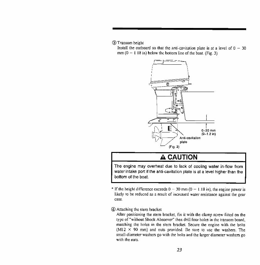
@I Transom height Install the outboard so that the anti-cavitation plate is at a level of 0 - 30 mm (0 - I IS in) below the bottom line of the boat. (Fig. 3)
water intake port if the anti-cavitation plate is at a level higher than the
* If the height difference exceeds 0 ~ 30 mm (0 - 1.18 in). the engine power is likely to be reduced as a result of increased water resistance against the gear case.
@Attaching the stem bracket After positioning the stem bracket, fix it with the clamp screw fitted on the type of “without Shock Absoever” then drill four holes in the transom board, matching the holes in the stem bracket. Secure the engine with the bolts (MI2 X 90 mm) and nuts provided. Be sure to use the washers. The small-diameter washers go with the bolts and the larger diameter washers go with the nuts.
23

The mounting holes may be drilled beforehand by referring to the dimensional drawing below.
I AA WARNING I
I We recommend that the bolt heads of the bolts face inward while the nuts are secured on the inside of the boat to prevent injury to the passengers.
Stem Bracket Dimensional Dradwing a) Manual tilting (Without Shock Absorber) types
24

b) Manual tilting (With Shock Absorber) types and types with power trim and tilt:
I A CAUTION I 1. Apply a sealing agent, such as silicon sealer, between the bolts and
the transom board holes when tightening the bolts. 2. Be sure to fix the motor securely with the bolts. Consult to the your
dealer.
After installing the outboard, make sure that its steering and tilt movement! are
not obstructed by any part of the boat. Also, the battery cables is fitted, make sure that it does not interfere with the movement of the outboard. From time to time, check the bolts (and clamp screws) for tighteness
2 Installing the Remote Control Device
I AA WARNING *To prevent accidental running of the engine, which could result in an
injury, DO NOT connect the battery until the installation of the remote control box and the motor is complete.
* Remove all the spark plug caps.
25

A CAUTION Be sure to follow the specific instructions for installing the remote control box.
The following explains the installation procedures for right-hand driving.
@Installing the remote control box
*Position the remote control box in a place where there will be no
interference with the handling of the controls, levers and switches.
Confirm that there are no obstacles in the passage of the remote control
cables. * Determining the remote control cable length:
Use distances “A” and “B” in the illustrations below as guidelines for the
length of the remote control cables, and add an additional 300 mm (one
foot). i.e.. Cable length=“A”+“B”+300 mm (one foot)
1 NOTE I
Do not sharply bend the remote control cable below a radius of 203 mm (8 in.) or less, as this will interefere with cable operation and get damage to the cable.
26

@Connecting the remote control cables to the remote control box
(a) Remove the back plate by loosening the two screws as shown.
r=iY
(b) Pass at least I I mm (0 433 in.) of the remote control cables through the
terminal eyes A. Securely lock the terminal eyes with lock nuts B.
Approx. lmlrn (0 63 In)
(c)Engage the outer groove of the shift cable on the remote control side
with the clamp groove of the housing. Insert a grommet, supplied with
the remote control box, into the clamp groove.
(d) Insert the shift arm pin into the terminal eye. and lock it with the E-ring.
Shl” arm
27

(e) Connect the throttle cable to the throttle am in the same way
cable was connected. (f) Reinstall the back plate.
as the shift
(g) Install the remote control box using the three screws. spacers, washers
and nuts.
Washer
I Nut
28

@ Connecting the remote control cables to the engine
(a) Detach the motor cover upper by turning the lever.
(b) Detach the bracket and set cord ass’y B and the remote control cables in
position.
After fixing the remote control cables to the bracket, rexcure the
bracket to the motor cover lower.
Grommet
Thronle cable
Battery Corde
29
Bat& Corde Gmmmet

(c) Detach the throttle and shift cable joints by removing the R-pins.
Thronle cable joint
R-pin
*Pass at least 15 mm (0.59 in.) of the remote control cables through the
terminal eyes. Securely lock the terminal eyes with lock nuts.
Cable joint
(d) Move the remote control lever to the “FORWARD” “NEUTRAL” and
“REVERSE” positions to confirm that the shift is working properly, then
set the lever to “NEUTRAL”
30

(e) Double-check that the remote control cables (i.e.. the throttle cable and
shift cable) have been connected correctly. Move the remote control
lever forward to the first point at which It engages (approx. 32 “). The cable which moves first when the lever is turned should be the shift
cable. Check that the shift lever is in “NEUTRAL” position and that the
free accelerator lever is fully closed when the remote control cables have been connected.
*The advancer am on the engine should be contact with the stopper of the
cylinder crank case ass’y so that the throttle valve of the carburetor is to be
fully closed condition.
Advancer arm
31

(f) Adjust the cable joints until the hole of each is aligned with the advancer arm pin. After adjustment, lock each cable joint with the nut and secure it with the R-pin
Nut
3 Connecting the Cords and Leads @Connect cord ass’y B to cord ass’y A~ @) Connect the pink and light-blue leads from cord ass’y A and B together
AAA DANGER Do not disconnect the electric couplers while the engine is running, as this will damage the CD unit and could result in a serious electric
shock.
32
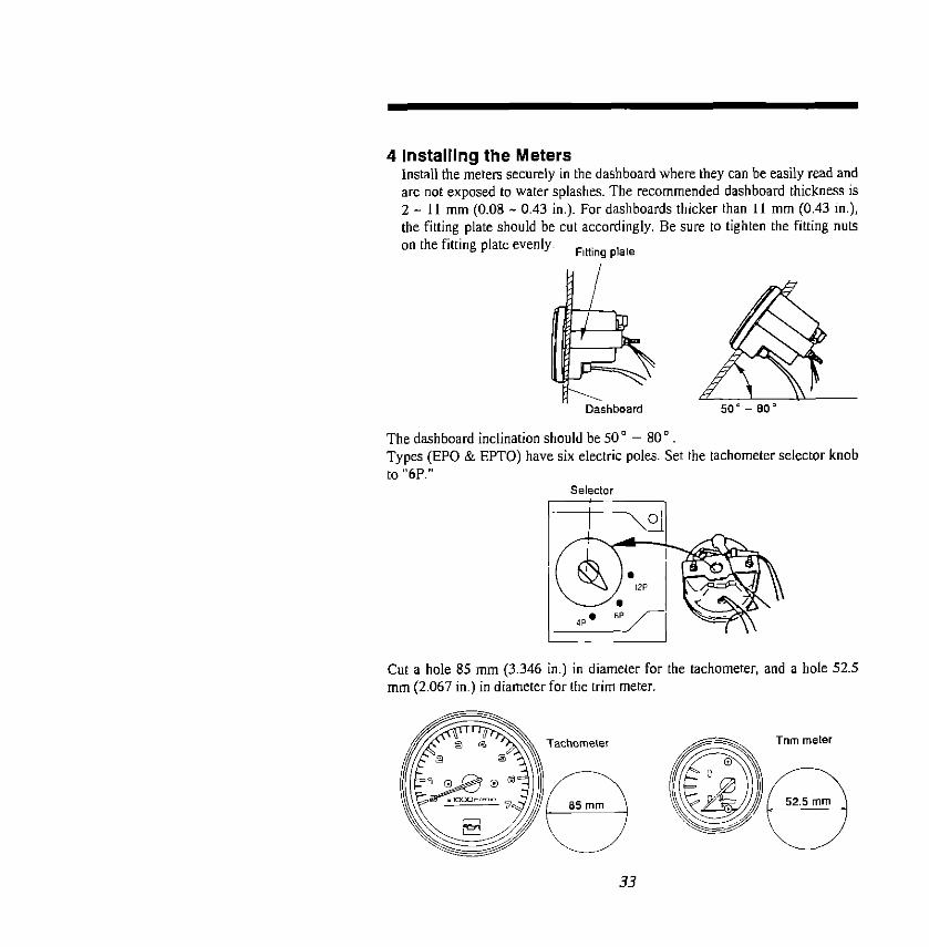
4 Installing the Meters Install the meters securely in the dashboard where they can be easily read and are not exposed to water splashes. The recommended dashboard thickness is 2 - 11 mm (0.08 - 0.43 in.). For dashboards thicker than 1 I mm (0.43 in.), the fitting plate should be cut accordingly. Be sure to tighten the fitting nuts on the fitting plate evenly~ Fining plate
Dashboard
The dashboard inclination should be SO” - 80” Tv~es (EPO & EPTO) have six electric poles. Set the tachometer selector knob
Cut a hole 85 mm (3.346 i ir I.) in diameter fc x the tachometer, and a hole 52.5 mm (2.067 in.) in diameter tar the turn meter

W Connection of Leads Tachometer: EPO EPTO Trim meter: EPTO Trim sender: EPTO
(optional)
Color Codes
B: black L: blue Lg: light green 0: orange P: pink R. red Sb: sky blue W: white Y: yellow
NOTE
The parts marked with % mark are to be wired when a Meter Lamp Switch (optional) is used.

5 Installing the Drag Link Assembly (Standard accessories for EPTO and EPO types)
AA WARNING Incorrect or unstable installation of the drag link assembly can result in an accident while driving the boat or breakage of the hull. Installation of the drag link assembly by your dealer is highly recommended.
I A CAUTION I Make sure that the steering cable and remote control cables are of the correct length measurement referring to the illustration. Kinks may be caused by sharp bends on excessively short cables, while the use of excessively long cables will result in unnecessary bends or loops. In both of these situations, extra stress is placed on the cables.
1 NOTE I
Depending on the steering cable manufacturer, spacers (optional) may be required.
@I Apply specified grease (marine type) to the inside of the bracket bolt and at other necessary locations as shown in the following diagram.
@Connect the drag link rod to the tip of the steering cable.
Tighten the rod using the self- locking nut, making sure that the rod can swing freely
3.5

@I Connect the other tip of the rod to the steering bracket with a bolt, using a collar and washer. The bolt head must face downward. Secure the bolt to the rod with a split pin.
spacer (Oplional)
Apply grease inside I
Torque to 2.4kg-m (17 Lbs-ft)
.45kg-m (iO.SLbs-ft) minimum and back off i/4 turn.
I AA WARNING I When the installation is completed, before starting the engine, check that the boat will turn to the left and right when the steering wheel is
turned left and right, respectively. Also, make sure that there is no obstruction to the steering movement through its full range in both directions and at all tilt angles.
I AA WARNING I Make doubly sure that the outboard motor and its related controls and meters are properly installed. Failure to do so may result in personal injury or damage.
b 36

6 Installing the Battery
I AA WARNING
I I
Remove all the spark plug caps from the spark plugs to prevent engine from starting. I
@Keep the battery in the designated battery space of the boat. Secure it tightly
and make sure it cannot be reached by water.
@Connect the red cord (positive (+)) to the positive (+) terminal of the battery.
@ Connect the negative (- ) cord connector of the black cord (negative) to the
negative (-) terminal to the battety
Required battety rating: 12V 70AH-I 2V lOOAH
AA WARNING Hydrogen gas is generated when a battery is charged. Therefore, keep the battery well ventilated during charging. Electric sparks, cigarette smoking and other sources of fire must be avoided in the charging area to prevent explosion of the battery. *The battery fluid (electrolyte) contains sulfuric acid. If any electrolyte is spilled on the skin, clothes, etc., wash with copious amounts of water and consult a doctor. Always use safety glasses and rubber gloves when handling the battery.
37

7 Removing the Battery
@ Disconnect the black cord connector from the negative (-) terminal. @ Disconnect the red cord connector from the positive (t) terminal.
AA WARNING I The above procedure for connecting and disconnecting the battery should be followed to minimize the possibility of creating sparks or an accidental short circuit.
I
NOTE
l.The battery cords should be of sufficient length to allow free movement of the engine.
2. Keep the battery cords neatly arranged, and protect them from damage (from steering, etc.)
3. The engine may not start if the cord connectors are loosely connected.
4. Be sure the battery is fully charged prior to installing the battery.
@Apply grease on the terminal of the battery before connecting the cords to the battery.
A CAUTION I
I The battery charging system and fuse will be damaged if the polarity (+ and -) is reversed. I
AA WARNING At the time of checking or servicing the battery, always disconnect the negative (black) cord first. (Also, take special care to avoid the possibility of a short circuit, which can be caused by a metal object touching the battery posts and the motor at the same time.
38

I A CAUTION I Do not add sulfuric acid (diluted or otherwise) battery may be damaged. Observe the procedures specified by the battery manufacturer.
A CAUTION
I Incorrect connection of the battery cord may result in damage being caused to the electrical system.
8 Installing the steering handle and main switch box (For EF/EFO/EFTO types)
I AA WARNING I Be sure that battery is not connected to the outboard to prevent accidental starting.
@I Position the throttle cable in the steering handle as shown in the illustration, and fix it with the nylon nut. Then. insert the plate Into the cable outer groove and secure it with screws.
39

@ Install 2 pieces of the bushing on the handle B and fix with 2 pieces of the bolt on the outboard.
@Apply grease on the sliding portions turning the handle to circulate all over. @Adjust the handle resistance by the friction bolts while moving up and down
the handle.
Handle B
Handle
Bolt
@Install the main switch box at a place where the driver is able to operate the switches easily. And confirm no obstacles at the cord passage before installing the main switch box. When the cord is excessively long. adjust tbe length by hauling the cord inside the upper motor cover.
9 Installing the Propeller
I AA WARNING 1 to disconnect plug cap from the spark plug to prevent
accidental starting. I
40

@Protection from galvanic corrosion
A CAUTION The use of a stainless steel propeller with an aluminum drive unit is likely to significantly accelerate the process of galvanic corrosion. Therefore, we recommend that you employ some type of corrosion protection for your boat and motor if you are using such a propeller, especially when boating in salt or brackish water. For more details on protection from galvanic corrosion, consult with your dealer.
0 Propellers
A CAUTION Use of an inappropriate propeller for your particular needs can cause serious damage to your outboard motor. Please read the information in the following subsection. check the Propeller selection table at the end of this manual, and consult your dealer for specific recommendations.
@Selecting the right propeller (a) The criterion for selecting the right propeller is that it should allow the
motor to operate at its recommended full-throttle rpm range when subjected to a normal load (see the chart below). The maximum engine speed (rpm) for this purpose is defined as the point where the boat is at
its maximum speed with the optimum trim for that speed.
In other words. propeller selection should not be based on the high rpm
resulting from an excessive tilt angle.
Generally speaking. there is a difference of 300 rpm behveen each
propeller pitch.
Recommended full-throttle RPM Range. (rpm)
RPM Range : 4.900 - 5,600
41

A CAUTION It is essential to change to a propeller of the correct pitch if the rpm at full-throttle operation is less than the range shown in the above chart. Failure to do so may result not only in reduced performance but also damage to the engine.
Washer Split Pin
\ \.
(b) If you experience reduced rpm due to any of the following situations after you have installed the propeller, change to a propeller with a lower pitch:
a. Operating in warmer or more humid weather b. Operating at a high altitude c. Operating when the bottom of the boat or the gear case is soiled d. Operating with an increased load such as a greater number of
passengers. towing a skier, etch
(c) If you are installing hvin outboard motors, it is recommended to try to use a higher pitch propeller. If your boat is used for water skiing or will be heavily loaded, use a lower pitch propeller.
42

I A CAUTION I The engine should not be operated at full throttle when the boat is fitted with a propeller for towing skiers or carrying a heavy load if no skier is being towed or the boat is lightly loaded.
(d) Installing the propeller
AA WARNING Before installing or removing the propeller, disconnect the spark plug caps, place the remote control lever in the “NEUTRAL” position, and remove the ignition key from the switch on electric starting. then place a block of wood between the anti-cavitation plate and propeller, to prevent accidental starting of the motor and protect your hands from the propeller blades while removing the propeller nut.
Follow the procedures described below to install a propeller on your outboard motor: @Apply a thick coating of specified grease to the propeller shaft splines. to
assist in preventing corrosmn. @ Powon the thrust holder on the shaft. @Turn the propeller until it is aligned with the propeller shaft splines. then
slide the propeller onto the shaft. @Fit the stopper and washer on the shaft. @Fit the propeller nut and tighten it with a torque wrench to 29.4 - 39.2 N.m
(3 - 4 kg-m/21.7 - 28.9 lb-ft). 0 Insert a cotter pin and bend it so that it remains in place
AA WARNING DO NOT disconnect the electrical harness while the engine is running. All models will continue to run and can be started with the
electrical harness disconnected.
43

Follow the above procedures in reverse to remove the propeller
AA WARNING If the engine rotation speed exceeds 5.700-6.100 rpm at full throttle, the Over Revolution Limiting System is activated automatically to limit the speed. Continuous running with this system activated may lead to engine trouble. Replace the propeller with the correct type immediately.
A CAUTION Severe damage can be caused to your outboard motor by the use of an unsuitable pitch of propeller, due to an excessively high engine speed when operating the motor at full throttle.
44

5. FUEL AND ENGINE OIL
AAA DANGER Since gasoline is highly flamable and toxic, observe the following precautions without fail when refueling: * Do not allow anyone other than an adult to refill the fuel tank. * Before refilling the fuel tank, stop the motor and remove the fuel tank
from the boat, to avoid the possibility of spilling gasoline on board. * Fuel expands when heated. Therefore, do not fill the fuel tank right
to the top, to avoid the risk of fuel overflowing. *Take full precautions not to spill any fuel. If any fuel is spilled, wipe it
up immediately. + Do not smoke near the fuel tank, and keep it away from naked
flames and sparks.
A CAUTION Be sure to use the specified gasoline and oil, or serious damage may be caused to your outboard motor.
The use of premium rated (super) unlead gasoline is recommended The minimum octane rating is 89 (research octane rating 91).
A CAUTION 1. Do not use gasoline containing alcohol, methanol (methyl) or
ethanol (ethyl). The use of such types of gasoline will void the warranty and repair costs will be at the owner’s expense.
2. Do not use white gasoline or “dirty” gasoline. 3. Do not use gasoline Pre-mixed with oil, such as that sold at gas
stations, since the octane rating and oil grade are unknown..
NOTE
We recommend the use of unleaded gasoline, for environment which will extend the life of the spark plugs.
45

Steel fuel tank Plastic fuel tank Fuel tank capacity ----- Approx. 227 liters (6 US. gal) Approx. 2.5 liters (6.6 U.S. gal) Engine oil ------~------ Use genuine Outboard Oil Engine Oil. If this oil is not available, use another NMh4A TC-W II certified outboard engine oil from another manufacturers Oil tank capacity: Approx. 2.6 liters ( 0.69 U.S. gal) (For EFOIEFTOIEPOIEPTO types)
I A CAUTION I Use only fresh gasoline. If gasoline is stored in the fuel tank for a prolonged period, gum and varnish may be produced which can damage the engine.
1 Non Auto-mixing Models (EF)
I AA WARNING I NEVER fill up portable fuel tanks on board to avoid fire or explosion resulting from spilled gasoline. If gasoline is ever spilled on board, wipe it up thoroughly. Fuel tanks must always be filled up on land.
@Fill the fuel tank with gasoline @Add engine oil to the fuel tank. The mixing ratio with gasoline is I:50 (one
pan oil to 50 parts gasoline). The mixing ratio during the running-in period is l:2S
@Mix well by stirring.
Mixing Ratio (non auto-mixing models)
“::“.,::I 46
2 Auto-mixing Models (EFO/ EFTO/ EPO/ EPTO)
AA WARNING I
Be sure to stop the engine before filling the oil tank. If the engine is not stopped, the turning flywheel may injure the operator or bystander. If any oil is spilled, wipe off any spilled oil afterward with a rag, or a fire could result from spilled oil.
aThe required amount of engine oil is automatically supplied from the oil tank, via the oil pump, according to the engine speed and load. Gasoline is fed through a separate feeding line.
AA WARNING 1
I Never feed gasoline into the oil tank. If gasoline is wrongly fed into the oil tank, drain all gasoline, and consult with your dealer.
I
47

Mixing Ratio (auto-mixing models, during running-in only)
Engine Oil : Gasoline
During running-in 1 50
After running-in Automatic. Fill up the engine oil tank regularly.
Oil tank cap
A CAUTION Be sure that no foreign matter or water enters the oil tank when filling it.
@ Oil pump air purge Visually check whether there is air in the oil through the vinyl pipe connecting the oil tank with the oil pumps If any air is present. purge it as follows: (a) Loosen the air vent screw on the oil pump to purge the air, and tighten it
when the oil. as seen through the vinyl pipe on the oil pump side, has been fully purged of air. (between oil tank and oil pump)
(b) Air m the fuel pipe between the oil pump and check valve is purged automatically when oil is fed. Operate the engine at idling speed until the air has been purged.
48

A CAUTION I Use mixture fuel until the air in the fuel pipe has been purged completely. Fuel mixing ratio
Gasoline 50 : Engine oil 1
I A CAUTION I
I Serious engine damage may be caused if any air remains in the oil injection system. I
T checkvalve
IN From oil filler
NOTE
Wipe off any spilled oil with a rag, and dispose of it by burning or another appropriate manner.
(b) When the oil level in the tank is
excessively low. air in the oil line is difficult to remove.
(c) Remove the air after filling up the Top oil
tank.
49

@I Low Engine Oil Level alarm
(a) EPO/EPTO
If the engine oil level in the oil tank falls below about 0.5 liters (0.131
U.S. gal), the pilot lamp in the hchometer will light up and the buzzer in
the remote control box will sound.
(b) EFOlEFTO
If the engine oil level in the oil tank falls below 0.5 liters (0.13 U.S. gal),
the alarm buzzer on the main switch box will sound.
Plloilamp in lachometer
@I Resetting the Low Engine Oil Level Alarm
Reduce the engine weed to trolline mm and steer toward secure area. Set the
remote controilevel.to “NEUTRAi”‘(the buzzer will stop).
Tom off the ignition switch, and fill up the oil tank with the recommended
engine oil.
After filling with oil, start the engine and carefully move the remote control
lever forward.
Confirm that the indicator lamp goes out and the buzzer (on applicable
models) does not sound.
A CAUTION l Running out of oil may result in severe engine damage. Be sure to
replenish the engine oil tank immediately if the alarm system activates.
* Check the oil level regularly. Refill the tank be fore the alarm level is reached. Return to the nearest port immediately at lowest possible speed and consult your dealer as soon as possible. Continuing to operate the engine can result in severe engine damage.
I
50
6. PRECAUTIONS BEFORE BOATING
I AA WARNING I Make sure that your boat and motor are in good condition and that you are fully prepared for emergencies before you begin boating. Each time before you set out. never fail to perform the inspection described in this manual.
AA WARNING 1 BEFORE starting the engine, always be sure that the boat is securely tied to a dock and there is sufficient space in front of and behind the boat.
* Check that you have sufficient fuel and oil for the intended journey. * Make a visual inspection of the propeller to check that it is not damaged * Check that the motor is securely mounted on the transom * Check that the tilt pin is securely installed in the correct position. * Check for any leaks in the fuel system connections and lines. * Check that the battery connections and all other electrical connections arc
* Check that the steering system moves easily; always be aware of any changes in the steering movement.
I AA WARNING I If you find that increased effort is needed for steering, or that binding, excessive free-play or unusual sounds occur while steering. contact
your dealer IMMEDIATELY. Avoid operating the boat before repairs are made, but if operation is necessary exercise extreme caution and travel at only a slow speed.
* Check that you have the necessaly emergency equipment on board, such as a floatation device for each passenger. fire extinguisher. signaling devices, anchor, paddles or oars. bilge pump. rope. first-aid kit, tool kit, emergency starter rope. flashlight, extra fuel and oil, etc.
51

* Check that the steering handle is securely in place. * Check that the shift and throttle linkages move smoothly and easily. * Check that all anchor nuts and bolts are properly tightened.
I A CAUTION I The air silencer cover must be in place when you operate the motor. Failure to attach the cover will unbalance the fuel calibration, possibly leading to power-head damage.
52
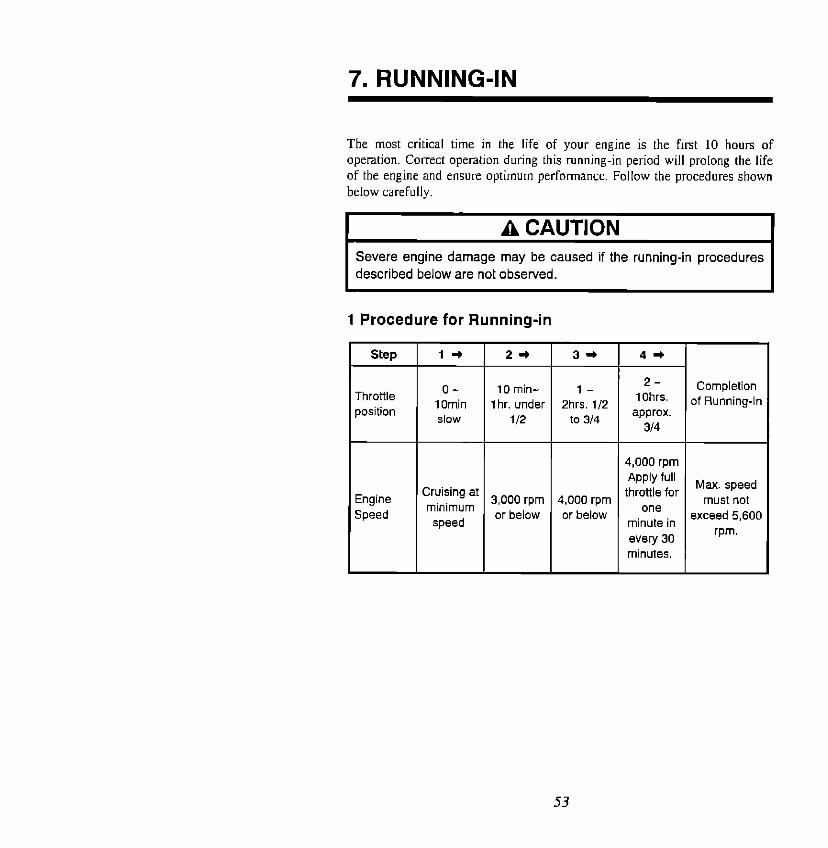
7. RUNNING-IN
The most critical time in the life of your engine is the first 10 hours of
operation. Correct operation during this running-in period will prolong the life of the engine and ensure optimum performance. Follow the procedures shown
below carefully.
A CAUTION Severe engine damage may be caused if the running-in procedures
described below are not observed.
1 Procedure for Running-in
Throttle position
O- 10 min- l- 2- Completion
1 Omin 1 hr. under 2hrs. l/2 IOhrs. of Running-In
slow i/2 to 3/4 2.ppPX.t.
314
Engine Speed
4,000 rpm Apply full
Cruising at throttle for Max. speed must not minimum 3,000 rpm 4.000 rpm
or below or below one
speed minute in exceed 5,600
every 30 rpm.
minutes.
53

2 Fuel Mixing Ratio during Running-h
EF
Type Dlwlng Rmllng-In After Running-In
Gasoline 25 : 1 Engine oil Gasoline 50 : 1 Engine a’
EFO/EFTO
EPOIEPTO
Fill fuel tank with
Gasoline 50 : 1 Engine oil gasoline and fill oil tank
with oil respectively.
A CAUTION Auto-Mixing Models Only 1. In addition to filling the oil tank. it is necessary to mix engine oil with
the gasoline (mixing ratio Gasoline 50 : 1 Engine oil) during the engine running-in period.
2. Replenish the fuel tank with pure gasoline only after the first 10 hours of running-in have been completed and the tank is completely emptied.
54

8. OPERATION
L AA WARNING I Always check that you have sufficient fuel to complete your trip before connecting the fuel tank to the outboard motor.
I A CAUTION Prior to starting the engine for the first time, or if you have not used the outboard for a long period (1 season or more), be sure to purge any air from the oil injection system. Refer to the FUEL AND ENGINE OIL section for information on the procedure to follow.
1 Starting the Engine 0 Preparations
(a) Loosen the air vent screw on the fuel tank cap. (b) Connect the fuel connecbx to the engine
55

@ Connect the fuel connector with engine side connector. Fix the fuel pipe with
the grommet.
I A CAUTION I
I Take into the consideration to have enough length of the fuel pipe at any range of the steering angle, and avoid to bend the pipe sharply. I
@Feed fuel to the carburetor by squeezing the primer bulb.
Engine side
Primer bulb
, Fuel tank side
56

@I Fit the lock in the emergency stop switch.
Emergency stop switch
\
Lock -
AA WARNING
I Be sure to connect the emergency stop langard to your body. The engine will shut down if the stop langard is disconnected. I
1 NOTE
The engine will not start unless this switch has been properly connected and locked beforehand.
switch works normally by starting and stopping the engine several
57

A CAUTION I Do not operate your outboard motor if you find that no water is discharged from the cooling water check port. Operating the motor in this condition can result in sever damage to the engine.
AA WARNING
I Before starting the engine, make sure that the boat is securely tied to a dock or that there is sufficient clear space in front of and behind the boat.
I AA WARNING Do not touch any electrical parts such as the ignition coils or the spark plug lead wires when starting the engine, to avoid the possibility of receiving a high-voltage electric shock.
EFIEFOIEFTO
@-A Confirm that the shift lever is in a position of “NEUTRAL” (N),
58

1 NOTE
Engine can be started only when the shift lever is at “NEUTRAL”(N) position. Neutral switch device prevents engine from accidentally starting if the lever is at another position.
AA.WARNlNG To protect operator against accidentally starting while the gear is in. these models have a neutral switch installed on the motor cover lower and the starter motor will not run in any other position than “NEUTRAL.” If you find any malfunction in these systems, consult your dealer immedately. Personal injury may be caused if the starter motor runs while the engine is in Forward or Reverse gear.
@-A Turn the throttle grip so that the indicator line meets the “START”
mark.
O-A Turn the main switch key one step clockwise and push the key to let the
choke work. (Do not push the key for warm engine.)
ON

@-A Turn the main switch key to “START position to start the engine,
ON TART
For the warm engine, turn the main switch key to “START’ position to start the engine without pushing the key.
) NOTE
When turning the main switch key to start the engine, a buzzer sound shortly, but this buzzer is not for any abnormality of the engine.
@-A When the engine has started, remove the hand from the key. The key will return to the original position automatically.
NOTE
If the starter motor fails to turn over, check that the battery terminal connections are tight and that the battery is fully charged.
A CAUTION I 1, Continuous operation of the starter motor for a long time consumes
the battery. Operate the starter motor for 3 seconds and take an interval for 5 seconds respectively.
2. Never operate the starter motor after the engine has started.
60

A CAUTION If the engine has started, check the flow of water from the cooling water check port. If no water flow is seen, stop the engine immediately to prevent damage on the engine by over-heating.
@-A When the engine has started. return the throttle grip to the “SLOW” position slowly to run at idling speed
A CAUTION Be ready to alter the throttle setting as soon as the engine starts. The engine should NOT be allowed to exceed 3,000 rpm while in “NEUTRAL” gear.
61

0 The reaction of the propeller rotation is quite/big because the outputs of the engine are extremely high. When running streight. adjust the trim angle and trim tab not to put the propeller reaction to the tiller handle.
When retuning the throttle grip to slow position suddenly. xc&relating immediately, or turing the tiller handle widely right or left, the tiller handle may be drawn to one side breaking the balance in running streight. A bigger power may be given on the tiller handle to turn one side when a bigger horse power engine is running at high speed, If the driver could not return the tiller handle, the boat will turn sharply which will lead the driver to be thrown overboard. Run the engine at proper speed depend on the occasion
AA WARNING 0 Never turn sharply and never accelerate or deaccelerate the
engine hastily.
0 Connect the emergency stop switch line to a wrist or a part of the driver without fail.
0 If the tiller handle is drawn even when running streight. take a balance adjusting the trim angle and trim tab. Specially in case the engine is used for commercial use, the load to the engine may change when running with cargoes and empty on the boat. In this case, it is necessary to operate the trim to be a proper angle not to drawn the tiller handle met each condition.
0 Never operate the tiller handle in standing condition.
A CAUTION l Before operating the engine, check and confirm whether the
throttle and clutch are in normal conditions, and check for looness of bolts, nuts and other parts.
0 Standard propeller fined on the engine has to be checked whether the propeller matches to the engine depending on the size and weight of the boat. The recommended engine rpm range is from 5200 to 5700rpm at wide open throttle. If the standard propeller could not obtain the recommended rpm range, consult your dealer and replace with a correct propeller.
62
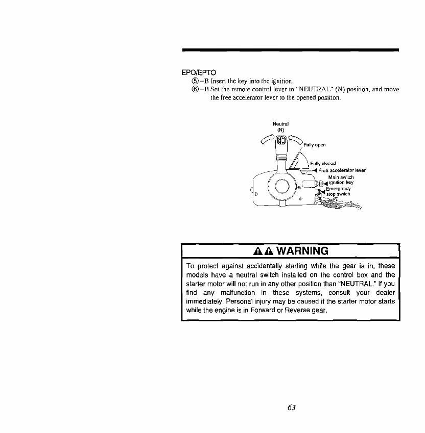
EPO/EPTO O-B Insert the key into the ignition. @-Et Set the remote contml lever to “NEUTRAL” (N) position. and move
the free accelerator lever to the opened position.
AA WARNING 1 To protect against accidentally starting while the gear is in, these models have a neutral switch installed on the control box and the
starter motor will not run in any other position than “NEUTRAL.” If you find any malfunction in these systems, consult your dealer immediately. Personal injury may be caused if the starter motor starts while the engine is in Forward or Reverse gear.
63
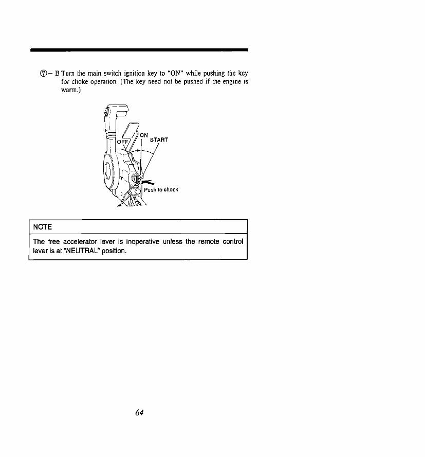
@ B Turn the main switch ignition key to “ON” while pushing the key for choke operation. (The key need not be pushed if the engine is warn.)
The free accelerator lever is inoperative unless the remote control lever is at “NEUTRAL” position.
64

@- B While keeping the key pressed, turn it to “START ” position.
If the engine is warm, there is no need to press the key for choking when turning it to “START’ position.
@- B When the engine starts, release the key to allow it to return to “ON.”
TART
6.5

I A CAUTION I Be ready to alter the throttle setting as soon as the engine starts.
The engine should NOT be allowed to exceed 3.000 rpm while in “NEUTRAL” gear. 1
A CAUTiON 1. Extended operation of the starter motor will run the battery down.
Operate the starter motor for a maximum of 3 seconds. If the engine does not start, wait for 5 seconds before operating the starter motor again.
2. NEVER operate the starter motor after the engine has started. 3. If the starter motor fails to turn over, check that the battery terminal
connections are tight and that the battery is fully charged.
2 Emergency Start Procedure - In case of trouble with the electric starting. @)Set the shift lever or the remote control lever to the “NEUTRAL.”
position
AA WARNING When the emergency start procedure is used, the start-in gear protection is inoperative. Hence, pay special attention to setting the shift lever to the “NEUTRAL” position, otherwise personal injury may
be caused by the boat starting to move unexpectedly when the engine has started with the shift at FORWARD or REVERSE.

I hey
AA WARNING Do not charge the battery with an external charger while it is on board. This practice can result in an explosion caused by the release of flammable gas.
@ Remove the motor cover upper and ring gear cover. then:
67

@Pull the choke knob fully out.
@ Wlen the engine is cold, turn the manual choke lever to “CLOSED”
position.
When the engine is warm. turn the manual choke lever to “OPEN” position
EF/EFO/EFTO
@-A Turn the throttle grip so that the indicator line is aligned with the “START” mark.
68

EPO/EPTO @B Lift up the free accelerator lever 113 to 112 of its stroke
@Turn the ignition key to the “ON” position.
69

@Wind the starter rope around the flywheel a few turns. Give it a sharp tug to start the engine. Use a socket wrench or similar object to get a firm grip on
the end of the rope
AA WARNING l DO NOT reinstall the ring gear cover or motor cover after the
engine has been started using the emergency start procedure. Attempting to do so may result in severe personal injury. Take special care to keep your hands, hair, clothing etc., away from the engine while it is running.
0 Do not continue to use the emergency start procedure for routine engine starting. Contact your dealer to have the starter system repaired as soon as possible.
0 Don’t touch the spark plug and/or high tention cord because high voltage electricity flows.
0 When fitting the motor cover upper on the motor, turn the shift lever or remote control lever to the “NEUTRAL” position and be careful to the moving parts.
0 Never charge the battery on the boat. Explosive gas will be generate when charging the battery.
70
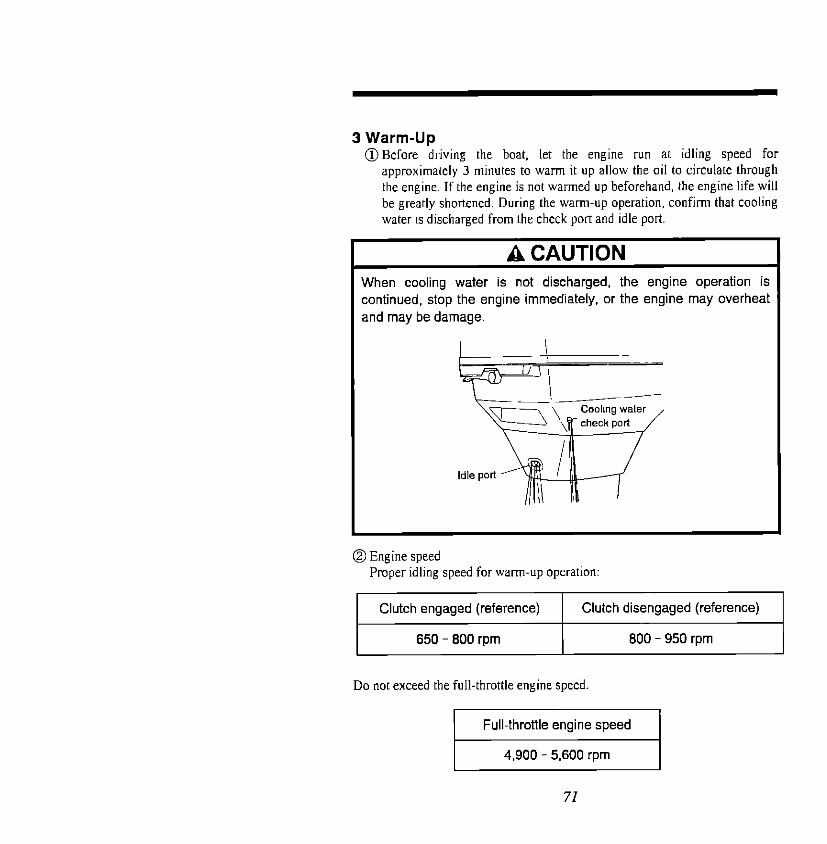
3 Warm-Up @Before driving the boat, let the engine run at idling speed for
approximately 3 minutes to warm it up allow the oil to circulate through the engine. If the engine is not warmed up beforehand. the engine life will be greatly shortened. During the warn-up operation. confirm that cooling water IS discharged from the check port and idle port
I A CAUTION When cooling water is not discharged, the engine operation is r continued, stop the engine immediately, or the engine may overheat and may be damage.
@Engine speed Proper idling speed forwarmup operation:
Clutch engaged (reference) Clutch disengaged (reference)
650 - 800 rpm 800 - 950 rpm
Do not exceed the full-throttle engine speed

A CAUTION 0 Do not rely only on the warning systems to indicate a malfunction
or to alert you to the need for maintenance. Make a point of regularly inspecting and maintaining your outboard motor to prevent any damage from occurring to it.
0 If either of the warning systems is activated while you are operating your outboard motor, stop the motor as soon as possible to correct the problem or return to the nearest port at the lowest speed, ask your dealer to check and repair it. Do not continue to operate the engine with any warning system activated, otherwise severe engine damege may result.
4 Warning Systems @ Over Revolution Limit System
This warning system is designed to automatically limit the engine speed
by activating when the engine reaches its maximum allowable speed
(5.950 ? 250 rpm). Once the system is activated, the engine is prevented
from running at a speed higher than the allowable rpm by a loss of firing
capability. If this occurs. check the rpm reading on the tachometer.
NOTE
When the Over Revolution Limit System is activated, the engine rotation becomes rough because of the loss of firing capability. Check to see whether the Over Revolution of the engine may be due to the use of a propeller of a smaller pitch than is appropriate for your boat. The correct propeller should be selected so that the engine rpm falls in the following range at full throttle.
4,900 - 5,600 rpnl
72

A CAUTION The Over Revolution Limit System is normaly only activated if an unsuitable propeller is fitted on your outboard or if some other part is damaged or malfunctioning. Either of these conditions can result in severe damage to your outboard motor. If the system is activated, contact your dealer as soon as possible to take the necessary remedial measures.
3 Overheating Warning System The Overheating Warning System is activated if the engine temperature
exceeds the preset level. This condition can be caused by a blocked water
intake port, the use of low-grade or unsuitable fuel, a blockage or
malfunction in the cooling water lines. etc. Once the system is activated, the
engine speed will automatically drop to 3,500 + 400 rpm. A warning buzzer
will also sound. (This is installed in the remote control box for the P-type
outboard motor.) If the Overheating Warning System is activated, immediately shift the gear to “NEUTRAL” position at a safe location.
Confirm that cooling water is discharged from the check port, then stop the
engine. Turn the ignition key to OFF. Remove any dirt or other Foreign
matter, if any, clogging the water inlets on the gear case.
AA WARNING If this system is activated by the water intake port being temporarily
blocked by a vinyl sheet, etc., the engine may suddenly accelerate again in the event that the material blocking the port comes off and the cooling water supply is restored. Such sudden acceleration of the engine may cause personal injury to the driver or passengers. Therefore, if the Overheating Warning System is activated, immediately shift the throttle lever to “LOW’ speed,
A CAUTION When the engine starts again and if the buzzer sound very often, consult your dealer to have a remedical measure.
73

5 Forward/Reverse Running @ EF/EFO/EFTO
Turn the throttle grip toward “SLOW” and move the shift lever quickly to “FORWARD” (F) or “REVERS” (R) when the engine speed has reached the lowest rpm.
I A CAUTION I When the engine is not in running, do not shift into the shift lever in the FORWARD and REVERS unnecessarily to protect the shifting device from damage.
74

A PAI lwnhl
1. Before moving the shift lever to “REVERSE” make sure the reverse lock is engaged (in UP position). (EFIEFO types)
2. Do not increase the engine speed excessively while reversing. A maximum limit of half-throttle is recommended when running in REVERSE for safe running.
Reverse lock lever
(with shock Absorber) I , LOCK
(witho”lShockAbsorber)
NOTE
The shift lever cannot be turned from “NEUTRAL” to “REVERSE” unless the throttle grip has been turned fully toward “SLOW.”
75

AA WARNING At the time of shifting from “FORWARD” to “REVERSE” or from “REVERSE” to “FORWARD,” stop once the shift lever at the “NEUTRAL” position and allow the engine to return to idling speed.
A CAUTION Impact damage can occur due to hitting an underwater obstacle when moving in either a forward or reverse direction. A high-speed collision with a log or other object floating in the water can transmit a damaging shock to both your boat and motor. Always drive with care. In case the outboard has hit the underwater obstacle hard, be sure to consult with your dealer for the check before normal use.
A CAUTION Always take extra care when reversing and watch out for underwater obstructions. NEVER accelerate the motor to high speed. Especially if the outboard hit an floating or under water obstacle when the boat is running in REVERSE, the shock of an impact could damage or break the transom.
76

@ EPO/EPTO While pressing the lock button on the remote control lever upward. swiftly move the lever to “FORWARD” (F) or “REVERSE” (R) to the point at which it engages (approx. 32 ’ forward or backward from “NEUTRAL”). Once the lever is moved further forward or backward, the engine will be accelerated.
Free accelerator level
A CAUTION 1. At the time of shifting from “FORWARD” to “REVERSE” or from
“REVERSE” to “FORWARD,” stop once the shift lever at the “NEUTRAL” position and allow the engine to return to idling speed.
2. Before moving the shift lever to “REVERSE” position, make sure the reverse lock is engaged (in UP position). (EPO)
Reverse lock ,e
LOCK
(with Shock Absorber) (without Shock Absorber)
3. Do not increase the engine speed excessively while reversing. A maximum limit of half-throttle is recommended when running in REVERSE for safe running.
77

AA WARNING 0 Since shifting and speed control is performed using the shift lever,
take care that you do not move the remote control lever forcefully when shifting. The boat may stat-l moving suddenly if the lever is moved quickly.
NOTE
The remote control lever becomes inoperative unless the free accelerator lever is in the fully closed position.
I A CAUTION Do not shift into gear unless the engine is running, to avoid possible damage to the shifting mechanism.
6 Shallow Water Running (EFTO/EPTO) Shallow water running is available only on the EFTO and EFTO types. Tilt up the engine using the Power Trim &Tilt System.
Set the outboard at higher position adjusting the same manner with the trim
angle adjustment. -
A CAUTION 0 When in shallow water running, take care that the water strainer is
submerged at all times and that water is continuously running out of the cooling water check port. If the water does not discharge from the cooling water check port, adjust the motor angle to tilt down a little.
0 Make sure that the motor does not strike the bottom, especially when running in REVERSE. If the motor strikes the bottom while reversing, the impact is transmitted to the transom, risking damage to both the motor and the boat.
78
7 Stopping the Engine
A CAUTION NEVER stop the engine immediately after full-throttle running. Keep it running for 2-3 minutes at idling speed (shift lever set to “NEUTRAL”) to allow it to cool down.
AA WARNING Never disconnect the electrical harness when starting the motor and when motor running. Also, remember to remove all spark plug caps from the spark plugs whenever you service the motor.
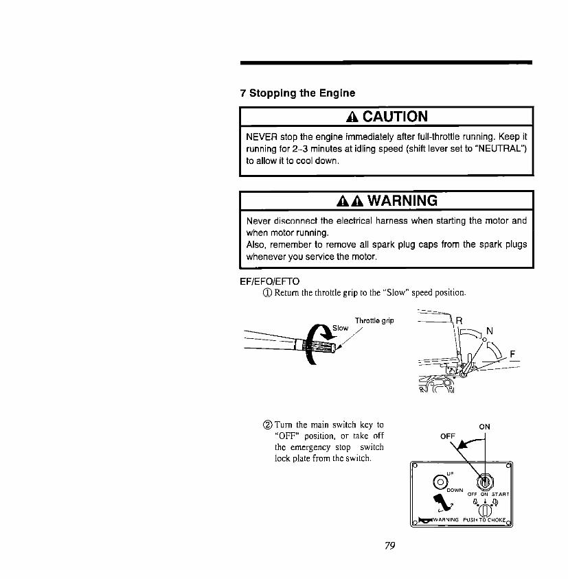
EF/EFO/EFTO @Return the throttle grip to the “Slow” speed position.
@Turn the main switch key to
“OFF” position. or take off
the emergency stop switch
lock plate-from the switch.
79

EPO/EPTO @Move the remote
for 2 - 3 minutes control lever to “NEUTRAL(N)“. and let to allow it to cool down.
NEUTRAL(N)
the idle
@Turn the ignition key to stop position or pull out the emergency stop switch lock plate. The engine will then stop. The engine can also be stopped by pressing on the emergency stop switch.
Emergency slop switch lock plate
I A CAUTION I *When another electrical equipment or accessory is fitted, the
electricity will be used for this and the battery discharges until the main switch is off.
80

I AA WARNING I
I Always remove the key when leaving your boat unattended, to prevent unauthorized use. I
@Disconnect the fuel ccnnector from the engine.
@Close the air vent screw on the fuel tank cap
NOTE
Disconnect the cables from the battery if the engine will not be used for an extended period of time.
81

8 Fuel Spill prevention Follow the procedure shown below if you are going to tilt up the engine,
remove it from the boat, or store It for a prolonged period. This is to prevent
fuel spilling from the carburetor and the formation of varnish or gum in any
remaining fuel during storage. @I Disconnect the fuel line.
@I Use up any fuel remaining in the carburetor by running the motor at
idling speed until stops. @Turn the ignition key to “OFF” and disconnect the positive (+) battery
lead to prevent accidental starting or a short circuit.
82
9. TRIM ADJUSTMENT
The following instructions explain how to set the best trim angle of the outbord.
I AA WARNING The power trim and tilt (PlT) switch located on the motor cover lower can be operated even when the ignition switch is off. Keep unauthorized people away from the motor at all times, to avoid the accidental activation of the system.
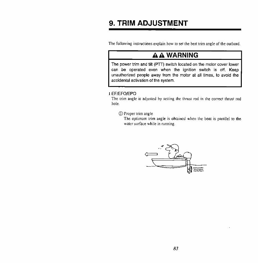
I EF/EFO/EPO The trim angle is adjusted by setting the thrust rod in the correct thrust rod hole.
0 Proper trim angle The optimum trim angle is obtained when the boat is parallel to the water surface while in running.
83

0 Improper trim rises too hiph.)
angle (bow
If the trim && is excessive,
the bow will rise out of the
water and the speed will decrease. Furthermore, the
bow may sway or the bottom may slam the water while cruising.
In this case. decrease the trim
angle by setting the thrust rod
in a lower hole.
@Improper trim angle (bow
dips into the water)
If the trim angle is too small,
the bow will dip into the water, the speed will
decrease, and water may
enter the boat.
In this case. the trim angle should be increased by
setting the thrust rod in a
higher hole.
84
I AA WARNING I Make sure that the trim angle is not too large, otherwise the boat may “porpoise” at higher speed which could result in the driver and passengers being thrown overboard. On the other hand, make sure that the trim angle is not too small, otherwise the boat may “plow” and become unstable.
I AA WARNING The operation of PlT when running has to be done at the remote control side. Never operate PlT on the motor when running to avoid a human accident and injury.
AA WARNING Always grip the steering wheel firmly, especially at the time of accelerating, deacelerating or adjusting the trim. When the boat reaches cruising speed, trim the outboard to obtain balanced steering conditions. During the trim adjustment process, the steering will pull toward one side or other until the correct balance is achieved. If the outboard is trimmed too far, the steering will then pull in the opposite direction. Another sign that you have trimed too far past, the balanced steering position is greater difficulty in steering and a decrease in performance.
2 EFTO/EPTO The Power Trim & Tilt System is used to set the desired trim angle of the
engine in relation to the transom shape, planing speed and load. It IS essential that the trim angle be adjusted correctly.
AA WARNING Incorrect adjustment will cause the boat to sway, reduce the engine performance and may cause unsafe steering conditions.
85

A CAUTION The following precautions should be applied if you are boating in shallow water with the motor trimmed beyond the trim limit cut-out point: 1. Keep the engine speed at IDLING RPM only. This is because the
swivel mechanism has no side support when the engine is trimmed beyond the trim limit.
2. Make sure that the water intake port is submerged at all times, to prevent overheating of the engine or water pump impeller damage.
@How to use the trim meter When the trim angle is set as desired, take a reading off the trim meter and record it for future reference.
86

@Improper trim angle (a) Engine trimmed “UP” (“trim out” characteristics)
If the trim angle is excessive, the
or the bottom may slam the water while cruising. In this case, decrease the trim angle by flicking the switch on the remote control lever to “DN.”
AA WARNING If the “trim our is excessive, the stability of the boat may be reduced. To correct instability when moving at high speed, reduce speed GRADUALLY and trim the motor “in” as required before picking up speed again. Do not reduce speed rapidly in this situation, otherwise the boat may become momentarily even less stable due to a sudden change in steering torque.
(b) Engine trimmed “DOWN (DN)” (“trim in” characteristics) If the trim angle is too small, the bow will dip into the water, the speed will decrease, and water may enter the boat. In this case. increase the trim angle by flicking the switch on the remote control lever to “UP.”
87

AA WARNING I Moving at high speed with the motor set at minimum ‘“trim in” may
cause unsafe steering conditions. Always check the handling characteristics of your boat each time you make any adjustment to the tilt angle.
0 Proper trim angle The optimum trim angle is obtained when the boat is parallel to the water surface while running.
A CAUTION I In the event that the power trim and tilt unit malfunctions, the motor
may lose its shock absorber protection. If an underwater obstruction is hit, it may also be unable to operate in REVERSE.
@I Manual tilting If the power trim & tilt switch is inoperative, turn the manual valve a few turns in the Manual direction. This will allow manual tilting of the engine.
A CAUTION Be sure to return the manual valve to its normal operating position (turned fully to the clockwise) to allow the reverse lock function to operate.
88

10. MOORING AND TRAILERING
1 Mooring with the motor Tilted Up When the outboard will not be used for a prolonged period or when mooring in shallow water. tilt the outboard up to prevent damage to the propeller and gear case.
EF/EFO/EPO 0 Disconnect the fuel connector from the outboard
@ Close the air vent screw on the fuel tank cap.
I AA WARNING Do not leave the air vent screw on the fuel tank cap open, or gasoline fume may be released from the vent.
89

Follow the procedure shown below if you are going to tilt up the engine, remove it from the boat. or store it for a prolonged period. This is to prevent fuel spilling from the carburetor and the formation of varnish or gum in any remaining fuel during storage. (a) Disconnect the fuel line. (b) Use up any fuel remaining in the carburetor by running the motor in the
running condition at idling speed until stoles (c)Turn the main switch key to “OFF” and disconnect the positive (+) battery
cord to prevent accidental starting or a short circuit.
A CAUTION Never raise or lower the outboard by means of the tiller handle, to avoid breaking the handle.
Types with Shock Absorber @-A Set the reverse lock lever on the starboard side to “RELEASE” by
turning it downward.
@-A Set the tilt stopper on the starboard side to “RELEASE” by turning it downward.
Till slopper

@-A Tilt the outboard up entirely. The outboard will be locked in the raised positmn.
@-A After tilting down the engine, return the revel’% lock lever to “LOCK”
side.
91

Types without Shock Absorber @-B Set the reverse lock lever on the port side to “RELEASE” by turning it
downward. @-B Set the tilt lever on the starboard side to “LOCK” by turning it upward. B-B Tilt the outboard up entirely. The outboard will be locked automatically
in the raised position. @-B To tilt the engine down. turn the tilt stopper lever downward (toward
“RELEASE”). Tilt the engine up slightly and then let it back down. (The reverse lock will be set automatically.)
A CAUTION Do not operate Pl7 holding by hand the tilt lever to tilt down the
outboard.
EFTO/EPTO @Disconnect the fuel connector from the engine.
Close the air vent screw on the fuel tank cap
E A CAUTION Do not shift into gear unnecessarily unless the engine is running to avoid damage to the shifting mechanism.
92

@Operate the PTT switch on the remote control lever to tilt the engine up.
(The main switch must be “ON.“)
93

@To tilting up the motor, keep pushing the PlT switch “UP” button for about 12 seconds until the motor sound changes.
@To tilting down the motor, keep pushing the PTT switch “DOW button about 12 seconds until the motor sound changes.
@The engine can also be tilted up using the switch installed under the motor cwer lower.
@Lock the outboard with the tilt stopper immediately after the engine has been tilted up.
0 Manual tilting
AA WARNING Do not leave the outboard unlocked. Accidental tilt down may cause personal injury.
If the power trim & tilt switch is inoperative, turn the manual valve a few turns in the Manual direction. This will allow manual tilting of the engine. Soon after reconditioning the PTT. return the manual valve to “POWER” side before operating the engine.
94
2 Mooring or Docking with Twin Outboards When leaving or approaching a dock, mooring. or for any other similar maneuvermg at slow speed, always use both outboards. Use the engine with the control nearest the operator to maneuver. and leave the other engine idling in NEUTRAL. The use of one control IS both effective and more convenienr In the event that this engine stole. you can Immediately transfer control to the other engine which has been on stand-by.
I A CAUTION
I I
Always have the stand-by engine running when maneuvering. Failure to do so may result in water being forced back through the underwater exhaust outlet, causing serious damage to the power head.
3 Trailering When possible. trailer your motor be in its normal running position. If your trailer does not provide adequate ground clearance, use the tilt stopper to secure the motor in the fully tilted-up position for trailering.
If you need more ground clearance. trailer the motor in a tilted position using a transom saver bar or similar device to support the weight of the motor.
AA WARNING When your boat is moving backwards, even a low-speed impact can transmit a very severe shock to the motor and its steering system. This can occur not only when the boat is in the water, but also when it is mounted on a trailer and is accidentally backed into a fixed object such as a pier or garage wall. If you hit any object, stop immediately and inspect your motor for any loosening or damage to the motor securing attachments swivel and stern brackets (clamps), and steering system parts. Also inspect the boat for possible structural damage. Tighten any loosened hardware and move slowly to shore. Before boating again, take your boat and motor to your dealer so that it can be thoroughly inspected for possible damage. Note that failure to inspect for damage after such an impact may result in a sudden loss of steering control at a later date, as well as reduced ability of the boat and motor to with stand subsequent impacts.
95

A CAUTION Do not trailer the motor in a tilted-up position unless the tilt stopper is engaged, to avoid possible damage to the hydraulic system.
AA WARNING Always disconnect the fuel line at the motor whenever the motor is not being used for a prolonged period of time, such as when the boat is moored or being trailered. 0 If a portable tank is used, coil the fuel line on top of the tank. 0 If a built-in tank is used, store the end of the fuel line as high as
possible above the top of the tank. These steps will prevent fuel from being siphoned from the fuel tank into the boat, protect the fuel line and connector from damage, and prevent sand or dirt from entering the connector.
A CAUTION I
Always check the bolts and nuts secured the lower unit of the motor to the boat transom or trailer when trailering. to prevent possible damage to the motor or transom.
96

4 Tilt Stopper Operation @I Engaging the tilt stopper
0 Set the motor in the fully tilted-up position.
0 Pull the tilt stopper down so that it rests on the stem brackets. A detent
will hold the tilt stopper in the trailering or stowed position.
0 Lower the motor so that the trail locks rest against the stem brackets.
Continue to activate the “DOWN” switch until the two trim rods are fully
retracted.
You will know that the rods are retracted when the sound from the power
trim and tilt unit changes.
@Disengaging the tilt stopper
0 Tilt the motor to the fully tilted-up position.
0 Move the tilt stopper up into the stowed position. Set the motor in the
fully tilted-up positmn before launching
I AA WARNING The power tilt mechanism should be used to lift and support the motor
the tilt stopper is disengaged.
97

EF/EFO/EPO (without Shock Absorber)
I AAA DANGER When taking out the motor from package or storing the motor taking out from the boat, never release the reverse lock lever. Otherwise it is dangerous since the stem bracket is not locked and up.
* Do not touch or get caught the reverse lock lever with a hand or foot. * Fix the stem bracket with a rope. * Be careful not to let a child touch with the reverse lock levers * Be careful to the jumping direction of the stem bracket to avoid a personal
injury hitting the jumping outboard.
Jumping direction
/ Stern bracket
98

11. DISMOUNTING THE ENGINE FROM THE BOAT
A CAUTION I Do not allow the lower unit of the motor to be higher than the power head during transportation or storage. Water may leak into the power head if the lower unit is in a raised position resulting in damage to the engine.
@I Stop the engine, disconnect the fuel connecror. and loosen drain screws on the carburetor to discharge any fuel. R&eve the discharged fuel into a container
AA WARNING I Beware of the danger of explosion. Spilled and vaporized gasoline may easily catch fire and explode. Be sure to fully discharge gasoline from the carburetor when transpotiing the engine. Wipe off any spilled gasoline with a rag.
@Disconnect the battery cables, the steering cable, the remote control cables
and the electrical cables.
@Remove the engine from the boat. Keep the engine in an upright position until water stops dripping from the gear case.
Always carry the outboard keeping the powerhead at a higher position than
the propeller when transporting the unit.
99

@ When carrying or storing the outboard, make sure that the side with the electric pump of the Power Trim and Tilt System faces down wards,
otherwise air may enter the pump system and affect the power trim and tilt
operation.
@ Never operate the motor of PTT when the motor is laid down on the ground.
100

12. ADJUSTMENTS
1 Remote Control Lever Movement EPO/EPTO
(Throttle friction adjustment screw)
To adjust the movement of the remote control lever, turn the throttle friction adjustment screw on the front of the remote control box. Turn the screw
clockwise for heavier movement, and counterclockwise for lighter
movement.
2 Trim Tab Adjustment If straight-line cruising cannot be achieved. adjust the trim tab located under
the anticavitation plate.
n If the boat veer- toward the right, set the trim tab in the direction of A.
n If the boat veers toward the left. set the trim tab in the dir&Ion of B.
Tumng right
101
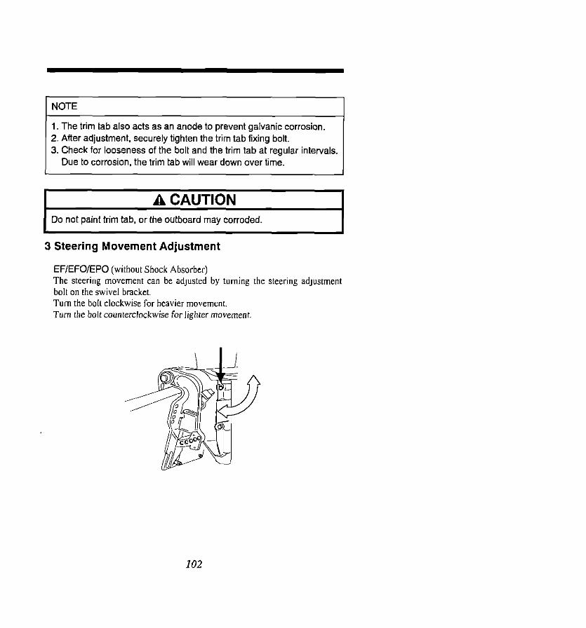
1 NOTE I
1. The trim tab also acts as an anode to prevent galvanic corrosion. 2. After adjustment, securely tighten the trim tab fixing bolt. 3. Check for looseness of the bolt and the trim tab at regular intervals.
Due to corrosion, the trim tab will wear down over time.
I A CAUTION A CAUTION
I Do not paint trim tab, or Ihe outboard may corroded. I Do not paint trim tab, or Ihe outboard may corroded.
3 Steering Movement Adjustment
EF/EFO/EPO (without Shock Absorber) The steering movement can be adjusted by turning the steering adjustment bolt on the swivel bracket. Turn the bolt clockwise for heavier movement. Turn the bolt counterclockwise for lighter movement.
I02

4 Throttle Grip Movement Adjustment
EF/EFO/EFTO Turn the friction adjustment screw on the steering handle to adjust the
movement of the throttle grip.
I03

13. INSPECTION AND MAINTENANCE
1 Daily Inspection Checklist Perfom the following checks before and after use.
Item P0lnt.s to Check
Fuel 0 Check the amount of fuel in the tank.
System 0 Check for dust or water in the fuel filters.
Lubrication 0 Check the amount of engine oil in the oil tank. System 0 Check for dust or water in the oil filter.
0 Check that the switch key functions normally.
Actlon
Replenist ClMll
Replenist
Clean
Remedy ( EPISCS
0 Check that the battery electrolyte level and specific Replenist gravity are normal. or
Electrical recharge Equipment
0 Check for loose connections on battery terminal. Retighten
0 Check that the emergency stop switch functions Remedy ( normally and make sure the lock plate is present. replaG
Throttle 0 Check that the choke solenoid for the carburetor Repke
System works normally.
0 Check that the clutch engages correctly when Adjust
Zlutch operating the remote control.
and 0 Visually check the propeller for bent or damaged ‘repeller blades.
Replace
System 0 Check that the propeller nut is tightened and the split pin is present.
nstallation 0 Check all the motor installation bolts with the boat. Tighten If Motor 0 Check the thrust rod installation. Tighten
;i?$ Tilt 0 Check working of the tilt up and down of the motor.
:ooling 0 Check that cooling water is discharged from the
Nater cooling water check port after the engine has
started.
rools and 0 To be ready tools and spare parts for replacing Fleffer to
jpares spark plugs. propeller, etc. page 128.
Steering 0 Check working of steering handle and remote
Ievices control.

N

“Power Trim & oil level and refill.
Check corrosion
and deformation

AA WARNING For items marked with an asterisk (*) in the above chart, it is recommended that only your dealer or a qualified service mechanic perform the required maintenance. If you have mechanical experience, you may perform maintenance on the unmarked items following the instructions in this section. However, if you are not confident that you can complete any of these maintenance tasks, ask your dealer to perform the maintenance for you.
I AA WARNING 0 Your personal safety and that of your passengers depends on how
well you maintain your outboard motor. Carefully observe all of the inspection and maintenance procedures described in this section.
0 If you do not have mechanical experience. ask your dealer to perform the necessary maintenance for you. By doing so you will avoid the risk of personal injury and possible damage to the motor.
A CAUTION The maintenance intervals shown in the above checklist apply to an outboard motor in normal use. If you use your outboard motor under severe conditions such as frequent full-throttle operation or frequent operation in brackish water, maintenance should be performed at shorter intervals. If in doubt, consult’ your dealer for advice. We strongly recommend that you use only genuine replacement parts on your outboard motor. Damage to your outboard arising from the use or malfunctioning of other than genuine parts is not covered under the warranty.
107

3 Flushing the Engine with Fresh Water When the engine has been used in salt water or polluted water, or when it is to be stored for a long petiod. wash the exterior and flush the cooling passage with fresh water using the flushing plug provided.
I AA WARNING
I I
When flushing out the engine, make sure to remove the plug cap from the spark plug and remove the propeller before hand. I
I AA WARNING I Never start or operate the engine indoors or in any space which is not well ventilated. Exhaust gas contains carbon monoxide, a colorless and odorless gas which can be fatal if enhaled for any length of time.
@Screw the flushing plug (hose adapter) into the wash hole on the gear case. Connect a water hose to the flushing plug. Be sure to secure the water strainer and sub-water strainer on the gear case before commencing the flushing operation.
Flushing plug
Sealing tape
108

@Place the motor in the nomnl vertical operating position. then open the
water tap.
A CAUTION ON NO ACCOUNT SHOULD THIS SPEED BE EXCEEDED. During and after the flushing operation, make sure that the motor remains in an upright position until all of the water has drained from drive shaft housing. The purpose of this is to prevent any water from entering the power head via the drive shaft housing or exhaust ports.
Adjust the flow of water so that a noticeable water loss occurs around the
rubber cups
@I Make sure that the shift lever is in “NEUTRAL” position and stafl the engine. Run the engine at idling speed and readjust the water supply as
required so that a noticeable water is seen again in rhe vicinity of the flushing device rubber cups.
@Increase the engine speed to approximately 1.500 to 2,000 rpm Check that water is discharging from the water check port.
@Continue the flushing operation for 3 to 5 minutes until the water being discharged.
@SStop the engine. turn the water supply off. and remove the flushing plug
from the gear case.
@I Wipe down the motor thoroughly. then spray or wipe on anticorrosion spray
so as to protect the finish of all parts.
I A CAUTION I Always make sure that water is supplied to the cooling system before starting the engine. Failure to do so could result in severe engine damage.
I09

4 Replacing the Propeller A worn or bent propeller will affect engine performance and may cause engine trouble.
I AA WARNING I When installing or removing the propeller, take special care to disconnect the spark plug caps, place the remote control lever in the “NEUTRAL” position, and remove the main switch key from the switch, then place a block of wood between the anticavitation plate and propeller, to prevent accidental starting of the motor and protect your hands from the propeller blades while removing the propeller nut.
@Pull out the split pin and remove the propeller nut and washer. @Remove the propeller by pulling it toward you. @Apply genuine grease to the propeller shaft, and thrust holder. @Mount the new propeller. @Fit the stopper and washer, securely tighten the nut and insert the new split
pin. @ Check for the loose fitting of the propeller.
Washer Split pin
Stopper
110

I AA WARNING I DO NOT disconnect the electrical harness when operating the motor. All models will continue to run and can be started with the electrical harness disconnected. Remove all spark plug connectors from the spark plugs when servicing the engine or propeller.
The propeller nut is tightened at tightening torque of 3.0-4.0 kg-m.
I A CAUTION I Never operate the motor with a loose propeller, or damage could be caused to the propeller shaft housing and gear case during acceleration and deceleration or when performing shifts.
A CAUTION Severe damage can be caused to your outboard motor by the use of an unsuitable propeller, due to an excessively high engine speed when operating the motor at full throttle.
5 Replacing the Spark Plugs
L AA WARNING I Remove the battery cords from the battery.
I
@ Remove the motor cover upper and switch key. @Remove the spark plugs by turning them counterclockwise. using the
socket wrench (21 mm) fitted with the handle provided.
I A CAUTION Do not use other tool for unscrewing the plug.
111

AA WARNING Do not touch the high-tension cables running from the ignition coil to the spark plugs while the engine is running or when it is being turned by the electric starter motor, not even for testing the high-tension cables or the spark plugs. The high-tension cables and the spark plugs generate very high electric voltage, which can cause a serious electric shock if touched.
When replaced with new spark plugs, tighten it by l/2-3/4 turn after the spark plug washer touches to the plug seat,
Tightening torque of spark plug 2.5-3.0 Kg-m
Specified spark plug NGK BBHS-IO, BRBHS-IO or CHAMPION L78C, RL78C (Plug gap: 0.9-1.0 mm)
A CAUTION 0 If a spark plug insulator has a whitened or a blackened
appearance, this may be due to either incorrect engine adjustment
or the use of an incorrect spark plug. Severe engine damage can be caused by using incorrect spark plugs. Consult your dealer before replacing the spark plugs.
0 Do not use other spark plug brands unless you are certain that they are equivalent to the specified brand. Engine damage caused by the use of nonspecified spark plugs may not be covered by the warranty.
0 When installing a spark plug, screw it in as far as it will go using your fingers, then tighten it with a wrench. Be careful not to overtighten or cross-thread the spark plug, since this will damage the aluminum threads of the cylinder head.
112

AA WARNING Do not use a spark plug with crack on the ceramic portion. Rough handling of a spark plug may crack its ceramic portion. This can lead to the danger of sparks being emitted from the damaged section, which could ignite fuel vapors under the engine cover.
@Check and replacing anode To prevent electrolytic cotmsion of the outboard motor. anodes are fitted on
the gear case, stem bracket and III the cylinder.
AA WARNING For replacing anode, remove the spark plug cap not to run the engine and check and renew the anode.
A CAUTION If the anode has worn out or no anode is fitted on the outboard motor, aluminum parts will get corrosion which lead painting peeled off and damage. Do not leave the consumed anodes on the outboard, or the outboard may be corroded.
113

For checking and replacing anode in the cylinder. remove the thermostat cap
T&tab/Anode on ~earcase
Thermostal cap
Anode in cylinder
6 Checking and Replacing the Gear Oil Q To check the level of the gear oil, set the motor vertically and remove the
spark plug caps and then. remove the upper oil plug and visually inspect
the level from the hole. The oil level should be at the lower edge of the
hole. If the oil level is depleted, add the specified gear oil until the level
reaches the bottom edge of the hole. Then fit the plug back in the hole and
tighten it.
Make sure that you replace the gear oil periodically, since this will prolong the life of your outboard motor.
114

@To replace the gear oil:
(a)Set the motor in a vertical
position and place a drain
pan under it.
(b)Take out the LOWER oil
drain plug first. and then
take out the UPPER oil level plug. Then drain the oil from
the gear case completely.
(c)Insert the oil tube nozzle into
the lower oil plug hole, and
squeeze the tube until the oil flows out of the upper plug
hole.
LOWH oil plug hole
(d)Install the upper oil plug.
Then remove the oil tube
nozzle and install the lower
oil plug. Renew the oil plug
gaskets every time of
replacing the gear oil.
UPPer oil plug
LDWW oil plug
115

I AA WARNING I Keep oil away from children and pets, and always dispose of used oil according to local regulation,
A CAUTION I Make sure that you do not operate the motor with no or less oil in the
color, contact your dealer immediately.
I A CAUTION Use only genuine gear oil or. if not available, an API (American Petroleum Institute) oil grade of GL.5, or SAE #SO or SAE #BOW. Required volume: approx. 700 cc (0.185 US. gal)
7 Fuel Line and Filters @ Fuel line
Visually check the fuel line for leaks, cracks, swelling, or other damage. If any damage is found in the fuel line. contact your dealer immediately to have it replaced.
A A WARNING
0 Fuel leaks can lead to a fire or explosion, causing serious personal injury. Ask your dealer to replace the fuel line. Do not service fuel line by yourself, if you find any leaks, cracks, or swelling in it.
0 Do not use gasoline containing methanol, since this can damage the fuel system and fuel tank due to its moisture attracting properties.
116

@Fuel Filters
Fuel filters are provided inside the fuel tank and on the engine.
(a) Cleaning the fuel tank filter
@ Remove the fuel gauge housing by loosening the four screws. @ Clean the fuel tank filter by washing it in clean solvent.
Fuel strainer
@Reinstall the fuel gauge housing. (b) Cleaning the engine fuel filter
@Remove the fuel filter cases. separate the filter cup from the black
cup by twisting the filter cup counterclockwise
@Take out the filter element. and check the filter element and the
O-ring in the black cap for damage. If any damage is found. replace
them.
@Clean the Filter element by washing it in clean solvent.
@ Replace the filter element in its original position in the black cap.
8 Check that the O-ring 1s positioned properly in the top section of the
black cap. then screw the filter cup back in.
0 Start the engine. and check that no fuel leaks from the vicinity of the
filter. Filter nut I ~

I AA WARNING 0 Take care for the ventilation when working in a house. 0 Make sure that the motor is completely stopped before cleaning
the fuel filters. 0 Do not smoke, and keep naked flames and sparks away while
working on or near any part of the fuel system. 0 Keep cleaning solvent away from children and pets, and always
dispose of used solvent in a proper manner. 0 Remove the air in the oil pipe after cleaning of the oil filter.
8 Checking and Refilling Oil in the Power Trim 81 Tilt Unit @Check the oil level of the reservoir tank as shown on the right while the
tank is in a vertical position. Tilt the engine up to check the oil level in the tank. Remove the oil plug by turning it counterclockwise using a plug wrench. then check if the oil level reaches the bottom line of the plug hole.
Oil level
I A CAUTION I
I Do not unscrew the oil plug with the engine tilted down, or pressurized oil in the oil tank may be discharged.
I
118

@Filling with recommended oil The use of Automatic Transmission Fluid (ATF DEXRON) is recommended.
@I Air purgmg from the power trim & tilt unit Entrapped air in the power trim & tilt unit will cause poor tilting movement. (a) With the engine mounted on the boat. (b) Turn the manual release valve a few turns in the Manual direction. (c)Tilt the engine manually up and down 5 ~ 6 times while checking the oil
level. (d) Close the valve by turning it in the Power direction.
A CAUTION I Be sure to return the manual valve to its normal operation position (turned fully to the right: clockwise) to allow the reverse lock function to operate.
119
14. WINTER STORAGE
AA WARNING 1. When the motor is out of the water, being transported, or in
storage, always remove the positive (+) battery cable to prevent accidental starting of the engine. Accidental starting when the motor is out of the water will cause overheating and damage to the engine due to a lack of cooling water.
2. DO NOT disconnect the electrical harness when operating the motor. The models will continue to run and can be started with the electrical harness disconnected. Remove all spark plug connectors from the spark plugs when servicing the engine or propeller.
When your outboard motor is in storage, this is a good opportunity to have it serviced and overhauled by your dealer. 1 Engine
@Wash the engine exterior and flush the cooling water system thoroughly with fresh water. Let the water drain completely. Wipe off any surface water with an oily rag.
@Drain all fuel from the fuel pipes. fuel pump and carburetor. and clean these parts. To prevent corrosion of the fuel tank. fill it up with engine oil-rich gasoline. Keep in mind that if gasoline is kept in the carburetor for a long time, gum and varnish will be genemted, causing the float valve to stick.
@Remove the spark plugs and feed genuine Engine Oil or storage fogging oil through the spark plug holes. The oil will be fed into the crank case from the air silencer attached to the carburetors. Turn the engine over several times while feeding the oil into it and make sure it is evenly distributed.
@Apply grease to the propeller shaft. @ Change the gear oil in the gear case. @Apply grease to all sliding parts, joints, nuts and bolts @Use a dry cloth to completely wipe off water and salt from the electrical
components. @Remove the fuel connector from the engine. @Attach the vinyl motor cover, and then stand the engine vertically in a
dry place.

2 Battery @Disconnect the battery cables. @Clean the exterior of the battery with fresh water or compressed air.
Wipe off any chemical deposits dirt and grease from the battery @Apply grease or vaseline to the battery terminals. @I Charge the battery completely before storing it for the winter @Recharge the battery once a month to prevent it from discharging and the
electrolyte from deteriorating. @Store the battery in a dry place with its cover attached.
A CAUTION 1, Do not allow the battery to discharge, since it can be damaged by
freezing. 2. When storing your outboard for the winter, open up all the water
drain holes in the gear case to permit any remaining water to drain out. If a speedometer is installed, disconnect the pickup tube and allow it to drain, then reconnect it after draining. Trapped water may crack the gear case or water pump case as a result of expansion when frozen. Check and replenish the gear case with case specified Gear Oil before storing the motor, to avoid water leakage into the gear case due to a loose lubricant vent plug or grease fill pulg. Inspect the gaskets under the lubricant vent and grease plugs, replace them if necessary, and reinstall the plugs.
3 Electric Starter Motor Coat the pinion gear and shaft of the electric starter motor with grease.
121

15. PRE-SEASON CHECK
Have your dealer check the engine before the season starts, or if you prefer, be sure to check the following items yourself:
@Check the electrolyte level. and measure the voltage and specific gravity of the battely.
Specific Gravity at 20°C Terminal Voltage (V) Charge Condition
1.120 10.5 Fully discharged
1.160 11.1 l/4 charged
1.210 11.7 II2 charged
1.250 12.0 34 charged
1.280 13.2 Fully charged
@Check that the battery is secure and the battery cables installed properly. @I Clean the engine oil filter. @ Purge air in the vinyl pipe connecting the oil tank to the oil pumps @Check that the shift and throttle function properly.
(Be sure to turn the propeller shaft when checking the shift function or else the shift linkage may be damaged.)
122

A CAUTION The following steps must be taken when first using the engine after
winter storage. 1. In addition to the oil in the oil tank, mix engine oil with the fuel in the
following mixing ratio and fill up the fuel tank completely with 22.7 liters (6 U.S. gal.): Mixing ratio: Gasoline 5O:l Engine oil Use premium (super) gasoline and genuine Outboard Motor Oil. If
this oil is not avaiable. use another NMMA TC-W II certified outboard motor oil from another manufacturer.
2. Purge any air from the oil filter assembly. 3. Warm up the engine for 3 minutes with the remote control lever in
“NEUTRAL” position. 4. Run the engine for 5 minutes at the slowest speed. 5. Run the engine for 10 minutes at half speed.
In steps 2 and 3 above, the oil used for winter storage inside the engine will be cleaned out, and optimum performance will be assured.
6. When the full volume, 22.7 liters (6 U.S. gal.), of gasoline mixed with oil has been used, fill up the tank with pure gasoline only. (For
the auto-mixino tvpes)
123

16. IF THE ENGINE IS SUBMERGED IN WATER
In the event that the engine is accidentally submerged in water. take the following countermeasures before handing it in for service at your dealer. @Take it out of the water immediately and wash it with fresh water to remove
all traces of salt and dirt 0) Remove the spark plugs, and drain the engine completely of water.
Turn the flywheel several times, using the starter rope. @Drain the fuel line and the carburetors @Inject copious amounts of gunuine Engine Oil or storage fogging oil into the
engine through the spark plug holes and the air silencer. Turn the flywheel several times with the starter rope while injection the oil to make sure the oil is evenly distributed.
0) After the above steps, it might be possible to start the engine. However, the electrical components and carburetor will soon deteriorate and become
inoperative. Therefore, be sure to have the engine overhauled by your dealer as soon as possible.
I AA WARNING I Keep gasoline away from naked flames and sparks, and always
dispose of unwanted fuel in the proper manner.
A CAUTION 1. If it is not possible to have the motor serviced promptly resubmerge
it immediately in fresh water to avoid exposing it to the air, and arrange to have it overhauled as soon as practicable.
2. If the engine cranks freely and no foreign matter such as weeds, mud, or sand seems to have penetrated it, try starting it again. However, if foreign matter has possibly entered the engine, follow the above procedures and take it to your dealer for servicing.
124

17. TROUBLESHOOTING
The Troubleshooting Checklist that follows may help to locate and remedy any minor malfunctions that might occur to the motor. The possible causes of each problem are listed in the order of likelihood. Although some of these causes may seem to be obvious at first glance. they are often overlooked at the time of dealing with a problem If the problem cannot be remedied by means of this checklist, immediately consult your dealer.
I AA WARNING I Before you begin making any checks or repairs to the motor. make absolutely sure that the battery cables are disconnected from the battery. Failure to disconnect the cables may result in personal injuty or damage to the motor.
12.5
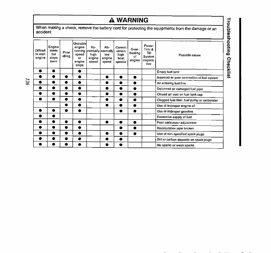
A WARNING When making a check, remove the battery cord for protecting the equipments from the damage or an
I accident.

I.1 I I I I I I I I Starter mobr failure I

18. ACCESSORIES LIST
fml w Remarks
Servicing Tools Tool bag 1
Sockel wrench (21 mm) 1 Wrench for spark plug
Sockel wrench (IO x 13 mm, 1
Sockelwrench handle 1
Pliers 1
Screwdriver (Phillips-type
and flat head) 1 Adapter-type
Wrench (7 x 8 mm) 1
Spare Parts Emergency starter rope 1
(1,600 mm,
Spark plug 2 NGKBSHS-IO (BREHS-10)
Split pin 1 3mmdia.xZSmmL
‘arts Bracket fixing bolts 4 12mm
‘a&aged with Bracket fixing nuts 4 12mm
Ingine Washers A, S 4 each A (large), B (small)
Fuel tank (with primer bulb) 1
Flushing plug 1 For flushing cooling waler
passage
Remote conlrol box 1 RC 4A or RC 40
Drag link 1 EPO. EPTO
Tachometer 1 EPO. EPTO
Trim meter (with Lead wire) 1 EPTO
Lead wire for me,er 1 EPD. EPTO
VInyI engine cove 1
I28

19. PROPELLER SELECTION TABLE
To ensure optimum performance, the propeller should match the boat type and its load.
10
11
12 E 13
14
15
Heavier
Load Mark Application
9 Optional
16.5
Lighler
Load t 17.5
Optional
Optional
Optional
Std. for NS608
Std. for NS708
Optional
Optional I
Optional
129

20. OPTIONAL ACCESSORIES
Consult with your dealer for details of the optional accessories.
1, Speedometer 2. Speedometer
(50 mph) (75 mph)
3. Hour Meter (engine operation hour counter,
5. Water Pressure
@ kr Lamp Switch
a 5. Water Temperature
Meter

14. Extension cord (2 m) for trim mefer
17. Grease 16. GearOil wg.25og) (260 cc. 500 CC)
16. Touch-up Spray 20. Engine Oil 5 liters (1.3 U.S. gallons)
131

21. ASBESTOS PRECAUTIONS
I-
i I Cylinder Head Gasket x 2 I Cylinder Head Cover Gasket X
I Thermostat Cap Gasket X I Exhaust Cover Gasket X
Blind Plate Gasket X Inlet Manifold Gasket X Pump Body Packing X
I Drive Shafl Housing Gasket X I I Engine Base Gasket X
10 ! Exhaust Housing Gasket X X X X X X X NA NA
11 I Exhaust Pipe Gasket 12 ! PumpCaseGasket 13 i Guide Plate Gasket 14 ; Oil Plug Gasket 15 ; Water Plug Gasket 16 I Water Plug Gasket 17 1 Oil Tank Cap Gasket 16 I Float Chamber Gasket
The following precautions should be taken when handling any of the parts listed in the table below which contain asbestos. 0 Handle out of doors in a well-ventilated place, as far as possible. 0 Use hand tools or low-speed tools, equipped with an appropriate dust
extractor where possible. If high-speed tools are used, they should always be equipped with such an extmctor.
0 Dampen the part before cutting or drilling. 0 Dampen any dust generated, place it in a properly closed container, and
dispose of it appropriately.
Any part containing asbestos which is likely to release fibers during use should be replaced by a new part when worm
Materials of Gaskets and Packings:
Asbestos (X mark): Non-asbestos (NA mark)
132

Note:
133
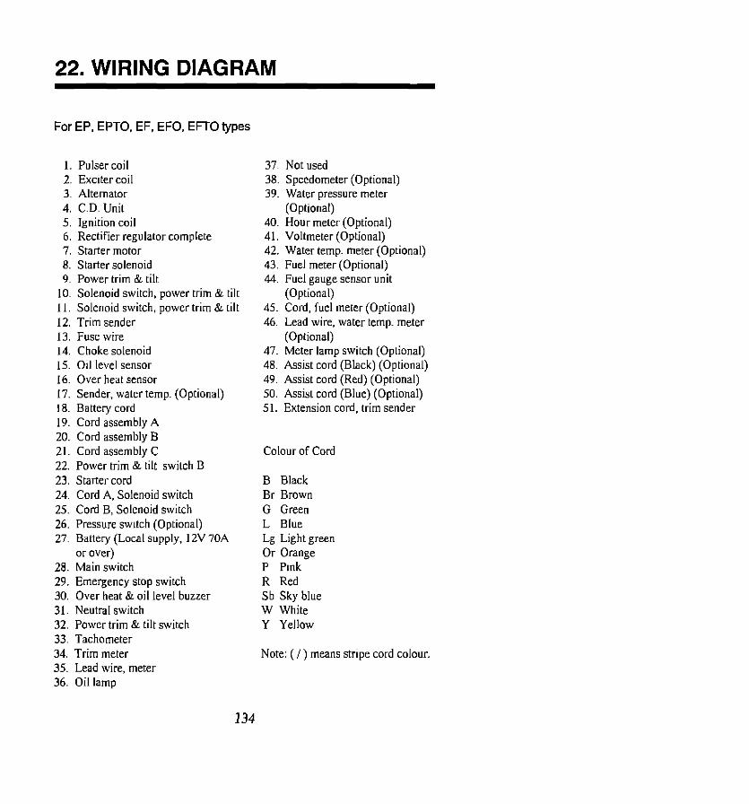
22. WIRING DIAGRAM
For EP, EPTO. EF, EFO. EFTO types
1. Pulset coil 2. Exciter coil 3. Alternator 4. C.D. Unit 5. Ignition coil 6. Rectifier regulator complete 7. Starter motor 8. Starter solenoid 9. Power trim & tilt
10. Solenoid switch, power trim & tilt I I. Solenoid switch, power trim & tilt 12. Trim sender 13. Fuse wire 14. Choke solenoid 15. Oil level sensor 16. Over heat sensor 17. Sender. water temp. (Optional) 18. Battery cord 19. Cord assembly A 20. Cord assembly B 21. Cord assembly C 22. Power trim & tilt switch B 23. Starter cord 24. Cord A, Solenoid switch 25. Cord B, Solenoid switch 26. Pressure switch (Optional) 27. Battery (Local supply. 12V 70A
or over) 28. Main switch 29. Emergency stop switch 30. Over heat &oil level buzzer 31. Neutral switch 32. Power trim & tilt switch 33. Tachometer 34. Trim meter 35. Lead wire, meter 36. Oil lamp
37~ Not used 38. Speedometer (Optional) 39~ water pressure meter
(Optional) 40. Hour meter (Optional) 41. Voltmeter (Optional) 42. Water temp. meter (Optional) 43. Fuel meter (Optional) 44. Fuel gauge sensor unit
(Optional) 45. Cord, fuel meter (Optional) 46. Lead wire, water tempt meter
(Optional) 47. Meter lamp switch (Optional) 48. Assist cord (Black) (Optional) 49. Assist cord (Red) (Optional) 50. Assist cord (Blue) (Optional) 51. Extension cord, trim sender
Colour of Cord
B Black Br Brown G Green L Blue Lg Light green Or Orange P Pink R Red Sb Sky blue W White Y Yellow
Note: (I) means stripe cord colour.
134

/n
136

--
EFO/EFTO
7 I B
7i
3 II -
A 8
I35
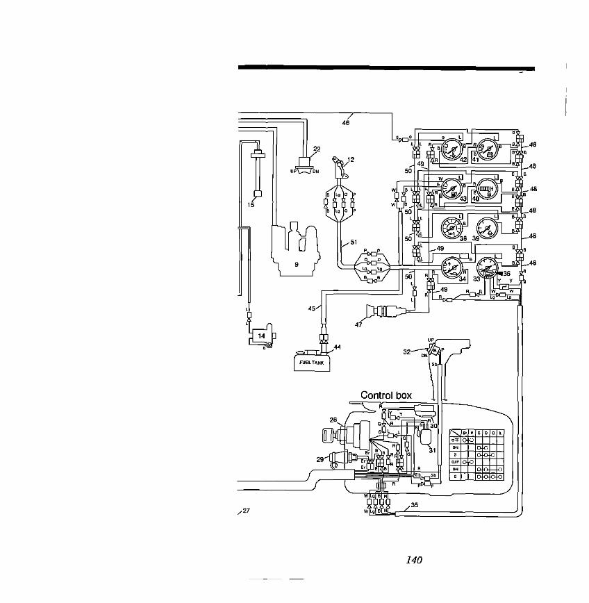
35 J)
140

--- --
EPOIEPTO

I:
;~, .:i’ , r;

Edition: July 1992 Printing: July 1992 Printed in Japan
Pub. No, M-462 T-2070-500-S