
SAEP-321 Performance Qualification Testing and Certification of Saudi Aramco Welders
Upload
venkatasubramaniCategory
view
997download
107
Previous Issue: 3 June 2008 Next Planned Update: 3 June 2013 Revised paragraphs are indicated in the right margin Page 1 of 30 Primary contact: Nasri, Nadhir Ibrahim on 966-3-8760162
Copyright©Saudi Aramco 2009. All rights reserved.
Engineering Procedure
SAEP-311 13 September 2009
Installation of Hot Tapped and Stopple Connections
Piping Standards Committee Members Nasri, Nadhir Ibrahim, Chairman Dib, Tony Georges, Vice Chairman Balhareth, Nasser Mohammad Bannai, Nabeel Saad Holland, Brad John Khashab, Jaafar M. Lewis, Trevor Mahmoud, Khalid Ahmed Phan, Howard Cong Rafie, Nader Yusof Rao, Sanyasi Rasheed, Mahmood Ayish Sharif, Talal Mahmoud Shiha, Saad Mohammed Swar, Ahmad Hamad
Saudi Aramco DeskTop Standards Table of Contents 1 Scope............................................................. 2 2 Conflicts and Deviations................................ 2 3 References..................................................... 3 4 Definitions...................................................... 4 5 Responsibilities.............................................. 5 6 Limitations on Hot Tap and Stopple Applications............................... 8 7 Safety Requirements.................................... 10 8 Technician Certification:............................... 11 9 General Design Requirements..................... 11
Document Responsibility: Piping Standards Committee SAEP-311
Issue Date: 13 September 2009
Next Planned Update: 3 June 2013 Installation of Hot Tapped and Stopple Connections
Page 2 of 30
Table of Contents (Cont'd.) 10 Limitations on Materials................................ 13 11 Limitations on Flow and Pressure during Hot Tapping....................... 13 12 Documentation............................................. 13 13 Installation and Welding of Hot Tap and Stopple Connections............... 15 14 Pressure Testing and Inspection................. 17 15 Stoppling...................................................... 21 Appendix A – Applicable Forms......................... 25
1 Scope
1.1 This SAEP provides procedures for the installation of hot tap connections to
piping and tanks while in service.
1.2 Also included is procedure for plugging pipes through hot tapped connections
(stoppling).
1.3 Hot tapping and stoppling are complex operations to be performed by trained
technicians with the support of experienced engineers. This SAEP is not intended
to detail all aspects of the operations and does not include adequate information to
enable it to be used as an instruction manual. The equipment manufacturer's
instruction manuals and data sheets will also need to be referenced and utilized.
1.4 The work to be performed after the hot tap and stopple operation is not within
the scope of this document.
2 Conflicts and Deviations
2.1 Any conflicts between this Procedure and other applicable Saudi Aramco
Engineering Procedures (SAEPs), Engineering Standards (SAESs), Materials
System Specifications (SAMSSs), Standard Drawings (SASDs), or industry
standards, codes, and forms shall be resolved in writing by the Company or
Buyer Representative through the Manager, Consulting Services Department of
Saudi Aramco, Dhahran.
2.2 Direct all requests to deviate from this standard in writing to the Company or
Buyer Representative, who shall follow internal company procedure SAEP-302
and forward such requests to the Manager, Consulting Services Department of
Saudi Aramco, Dhahran.
Document Responsibility: Piping Standards Committee SAEP-311
Issue Date: 13 September 2009
Next Planned Update: 3 June 2013 Installation of Hot Tapped and Stopple Connections
Page 3 of 30
3 References
3.1 Saudi Aramco References
Saudi Aramco Engineering Procedures
SAEP-302 Instructions for Obtaining a Waiver of a
Mandatory Saudi Aramco Engineering
Requirement
SAEP-310 Pipeline Repair and Maintenance
Saudi Aramco Engineering Standards
SAES-A-004 General requirements for Pressure Testing
SAES-D-008 Repairs, Alterations, and Re-rating of Pressured
Equipment
SAES-D-108 Repair, Alteration, and Reconstruction of Storage
Tanks
SAES-L-101 Regulated Vendor List for Pipes, Fittings and
Gaskets
SAES-L-110 Limitations on Pipe Joints and Components
SAES-L-150 Pressure Testing of Plant Piping and Pipelines
SAES-W-010 Welding Requirements for Pressure Vessels
SAES-W-011 Welding Requirements for On-Plot Piping
SAES-W-012 Welding Requirements for Pipelines
Saudi Aramco Materials System Specification
02-SAMSS-006 Hot Tap and Stopple Fittings
Saudi Aramco Standard Drawings
AE-036175 Detail of Heavy Welding Boss for Threaded
Connections to Vessels and Lines
AD-036643 Detail of Heavy Welding Boss for Socket Weld
Connections
AB-036719 Reinforcement of Welded Branch Connections
Saudi Aramco Forms and Data Sheets
Form SA 7235-ENG Hot Tap Data and Checklist
Document Responsibility: Piping Standards Committee SAEP-311
Issue Date: 13 September 2009
Next Planned Update: 3 June 2013 Installation of Hot Tapped and Stopple Connections
Page 4 of 30
Form SA 7627-ENG Hot Tap/Stopple & Reinforcement Calculation
Request
Saudi Aramco General Instructions
GI-0002.100 Work Permits
GI-0002.102 Safety Precautions for Pressure Testing
GI-1780.001 Atmosphere-Supplying Respirators
3.2 Industry Codes and Standards
American Petroleum Institute
API STD 598 Valve Inspections and Test
API RP 2201 Procedures for Welding or Hot Tapping on
Equipment Containing Flammables
American Society of Mechanical Engineers/Boiler and Pressure Vessel Code
ASME SEC VIII D1 Pressure Vessels
Pipelines Research Council International (PRCI)
PR-185-617 Criteria for Hot-Tap Welding (catalogue #
L51548)
PR-185-816 Review of procedures for Welding unto Pressurize
Pipelines (catalogue # L51601)
NG-18 Report # 175 Proof Testing of the Pre-Hot-Tap Branch
Connection (catalogue # L51561e)
Commentary Note:
Referencing to PRCI reports is intended for expanding knowledge and to locate sources of many of the technical basis for the requirements of this procedure. It is not intended to be a mandatory document.
4 Definitions
Hot Tap: Hot tapping is technique, performed using specialized equipment for cutting
a hole in a pipe or tank through a welded or bolted branch connection while they are
under pressure.
Lock-o-Ring Flange and Plug: This is a special flange and plug assembly designed to
allow the recovery of the hot tap valve while the pipeline is under pressure. The L-o-R
plug has an o-ring seal on its circumference and can be lowered into the bore of the
L-o-R flange, using a hot tap machine. The L-o-R flange has retractable segments that
Document Responsibility: Piping Standards Committee SAEP-311
Issue Date: 13 September 2009
Next Planned Update: 3 June 2013 Installation of Hot Tapped and Stopple Connections
Page 5 of 30
can be advanced into a groove in the circumference of the plug above the o-ring. These
segments retain the plug in position so that the valve can be depressurized and removed
and replaced with a blind flange or permanent valve.
Sandwich Valve: This is a gate valve designed to have a short face to face dimension
used as a temporary valve for stoppling. They are also used for hot tapping when the
connection will only be used temporarily or when the reach of the hot tap machine is
insufficient to complete a hot tap through a conventional valve. These valves cannot be
operated unless the pressure is equalized across the gate.
Stopple: A stopple is an articulated pipe plugging device, normally inserted through a
stopple split tee with a full line size hot tapped opening, while the line is pressurized.
Saudi Aramco has stoppling equipment for pipe sizes from 1" to 60".
Stopple Split Tee: A stopple split tee is a fitting designed with dimensional
requirements to suit the stopple plugging head. These fittings shall be purchased in
accordance with 02-SAMSS-006.
5 Responsibilities
5.1 The engineering group that prepares the calculations, design drawings and
installation procedures is responsible for the hot tap design. The detailed hot tap
installation design package shall be approved in writing by the facility
Operations or Engineering Superintendents, or higher. The responsibilities and
involvement of relevant organizations are detailed below.
5.2 Initiating Organization
5.2.1 The initiating organization will be either one of the following:
The Operations Engineering Organization when the work is being
undertaken by the Operations Organization.
Project Management with the approval of the Area Operations
Superintendent and Operations Engineering General Supervisor /
Superintendent in the case of tying in new installations, constructed
by Project Management to existing facilities.
5.2.2 The initiating organization shall prepare a design package for each hot
tap that will include fully dimensioned drawings, a materials list,
Direct Charge Requisitions and welding procedures.
5.2.3 The initiating organization shall appoint a Responsible Engineer to
carryout the following duties and responsibilities:
5.2.3.1 Be responsible for the overall coordination of the hot
Document Responsibility: Piping Standards Committee SAEP-311
Issue Date: 13 September 2009
Next Planned Update: 3 June 2013 Installation of Hot Tapped and Stopple Connections
Page 6 of 30
tapping activities. This is to ensure that designers,
constructors, hot tap unit, facility operations and/or
engineering, project management and operation/project
inspection staff cooperate closely during all phases of the
hot tapping operations.
5.2.3.2 Initiate form 7627-ENG, "Hot Tap/Stopple and
Reinforcement Calculation Request" and complete form
7235-ENG, "Hot Tap Data & Checklist" in accordance with
appendix A.2 and A.3.
5.2.3.3 Make all necessary arrangements for the preparation of the
new connection. (i.e., location, excavation, scaffolding,
pipe inspection, surface preparation, Installation, Welding
& Testing).
5.2.3.4 Arrange for a team, consisting of himself, Operations, the
responsible inspector and a representative of the Hot Tap
and Stoppling Unit, to survey the general hot tap location in
order to specify and mark the hot tap locations and number
(obtained from Form SA 7627-ENG) alongside each hot tap
location.
5.2.3.5 For stopple installation, make sure that the Hot Tap Unit
conducts pipe roundness check to ensure that it meets the
requirements stipulated in Table-1 of section 9.7 and mark
the exact location of the stopple.
5.2.3.6 Make available at the site a copy of the latest version of this
procedure and the installation design package during the
entire installation process.
5.2.3.7 Revise existing Saudi Aramco drawings, P&IDs, or
preparing new drawings, as may be required, because of the
hot tap installation.
5.2.3.8 Ensure that stopple or hot tap split tees with the L-O-Ring
plug to be delivered to the Hot Tap Unit shop in Dhahran to
be checked prior installation.
5.3 Hot Tap and Stopple Unit/N.A. Pipelines Department
The Hot Tap and Stopple Unit is responsible for the following:
5.3.1 Review and initial the design package.
Document Responsibility: Piping Standards Committee SAEP-311
Issue Date: 13 September 2009
Next Planned Update: 3 June 2013 Installation of Hot Tapped and Stopple Connections
Page 7 of 30
5.3.2 Review form 7235-ENG and ensure that the hot tap equipment
required to perform the hot tap is available and validated.
5.3.3 Perform the hot tapping and/or stoppling operation in accordance with
this procedure and an approved detailed design package.
5.3.4 Review and approve any Direct Charge Requisitions prepared as part
of the design package for stopple sealing elements, hot tap tees, stopple
split tees, or Lock-O-Ring flanges prior to issuing for purchase.
5.4 Inspection Organization
The responsible Inspection Unit shall be responsible for the following:
5.4.1 Review and concur with the design package prior to the start of the
installation.
5.4.2 Ensure that the connection is installed in accordance with the design
package.
5.4.3 Inspect and determine the minimum pipe wall thickness at the tie-in
weld areas by a continuous UT scan along the lines to be welded and
record this on the applicable form in Appendix A.1 of this procedure.
5.4.4 Review the welding procedure specification (WPS) and ensure that it
has been approved by Consulting Services Department.
5.4.5 Approve the fit up of the branch connection/split tee to the pipe prior to
welding.
5.4.6 Inspect the branch connection/split tee, before and during the
installation, for compliance with the approved drawings and welding
procedures.
5.4.7 Confirm that the hydrostatic test pressure for the branch connection is
correct at the time of the test, as prescribed in Section 4 of Form
SA 7627-ENG.
5.4.8 Verify that calibrated pressure gauges and relief valve are properly
installed for hydrotesting.
5.4.9 Inform the Responsible Engineer if the seam weld or any other
projection needs to be ground flush with the pipe surface to permit
proper UT scanning or fit-up of the split tee or reinforcing sleeve.
5.4.10 Scan the weld zone and 50 mm (2 inches) each side of it.
Document Responsibility: Piping Standards Committee SAEP-311
Issue Date: 13 September 2009
Next Planned Update: 3 June 2013 Installation of Hot Tapped and Stopple Connections
Page 8 of 30
5.4.11 Mark the inspected area permanently for future reference and
identification.
5.4.12 Consult with the Responsible Engineer and the responsible Operations
Engineering Organization if ultrasonic readings indicate a lamination
or evidence of hydrogen induced cracking (HIC) damage in order to
relocate the hot tap position. CSD and the proponent group shall be
notified of this condition.
5.5 Construction or Maintenance Unit
The construction or maintenance units are responsible for ensuring that
approved welding procedures and qualified welders are employed.
5.6 Consulting Services Department
Approve the welding procedure specification (WPS).
5.7 Loss Prevention Department
In the case of stoppling activities, the Loss Prevention office responsible for the
area where the stopple activities will commence shall be notified and provided
with procedures for review and be part of the site survey team.
5.8 OSPAS
OSPAS shall ensure operation stability prior and during pipeline hot tap and
stopple operation. OSPAS shall inform upstream and downstream facilities with
ongoing work activities.
6 Limitations on Hot Tap and Stopple Applications
6.1 Welding and hot tapping shall not be allowed in the following cases.
6.1.1 The operating pressure of the pipeline or tank may exceed the
maximum operating pressure of any of the hot tap or stopple
equipment and their components while it is installed.
Commentary Note:
All hot tap and stopple equipment must be stamped with its maximum operating pressure and revalidated according to this procedure.
6.1.2 The pipe contains flammable materials below atmospheric pressure.
6.1.3 The pipe contains a combustible mixture.
Document Responsibility: Piping Standards Committee SAEP-311
Issue Date: 13 September 2009
Next Planned Update: 3 June 2013 Installation of Hot Tapped and Stopple Connections
Page 9 of 30
6.1.4 Hot tapping on the roofs of cone or floating roof tanks in hydrocarbon
service.
6.2 Welding and hot tapping shall not be performed in the following cases unless a
detailed design and installation procedure has been approved by the Chairman of
the Piping Standards Committee.
6.2.1 Hot taps on air lines with compressed air if there is any possibility of
hydrocarbon contamination, unless the equipment being tapped is
thoroughly cleaned and inerted prior to welding.
Commentary Note:
Most industrial compressed air systems will have hydrocarbon contamination from compressor lubricating oil and will therefore required being inert.
6.2.2 Any pressure vessel, heat exchanger, fired heater or boiler,
manufactured in accordance with ASME Boiler and Pressure codes.
This is dictated by SAES-D-008.
6.2.3 The pipe contains any of the following:
a) Liquid acids
b) Caustic
c) Elemental Sulfur
d) Oxygen
e) Chlorine
f) Ammonia
g) Potential toxic material that would be injurious to personnel by
contact.
6.2.4 The material to be welded may suffer metallurgical or physical
deterioration from heating or requires post weld heat treatment.
6.2.5 The pipe has a corrosion or heat resistant lining such as metal lining or
cladding.
This restriction does not include internally coated piping but the
damage that will result to the coating by hot tapping should be
considered by the Operating Department.
6.3 Welding and hot tapping shall not be performed in the following cases unless a
detailed design and installation procedure has been approved by the Piping
Standards Committee Chairman with endorsement of the Proponent.
Document Responsibility: Piping Standards Committee SAEP-311
Issue Date: 13 September 2009
Next Planned Update: 3 June 2013 Installation of Hot Tapped and Stopple Connections
Page 10 of 30
The pipe or surface temperature is at or below zero degrees centigrade (0°C).
6.4 Hot taps shall not be made directly upstream of sensitive equipments such as
pump suction piping or control valves unless facilities exist to prevent chips and
shavings from entering the equipment.
7 Safety Requirements
7.1 All work shall be in strict compliance with GI-0002.100, Work Permit System.
7.2 The Operations Superintendent will assure that both Operations and the
Installation Organization have the proper safety and fire protection equipment
on site and in workable condition prior to the start of the job and that all relevant
personnel are notified of the scheduled hot work.
7.3 Precautions against H2S and other hydrocarbon or hazardous releases.
7.3.1 If a potential exists for a Hydrogen Sulfide release (or other toxic gas)
at a work site, all personnel involved shall be provided with an
appropriate breathing apparatus. (Refer to GI-1780.001, "Atmosphere-
Supplying Respirators").
The responsible operation representative or the work permit issuer
shall make sure that a person certified as a gas tester shall continuously
monitor the work site for the presence of hydrocarbons and hazardous
gases during the work activity using calibrated instruments and
established gas testing procedures.
7.3.2 When welding on hydrocarbon lines, the fire watch personnel shall be
clearly instructed that should a burn-thru occur, the fire jetting from the
pipe shall not be extinguished. This is particularly important if the
hydrocarbon contains H2S. If a burn-thru should occur, the Operations
Superintendent should immediately be notified to advise further action.
7.3.3 The chamber of the hot tap machine and valve shall be purged with
nitrogen and discharged to a safe location after cutting the coupon,
retracting the cutter and closing the tapping valve when any of the
following exist:
a) H2S concentration is greater than 10 ppm.
b) Low wind conditions exist and a gas or liquid hydrocarbon
release may create a hazard in the area or activate plant gas
alarms.
c) The work is in a confined area.
Document Responsibility: Piping Standards Committee SAEP-311
Issue Date: 13 September 2009
Next Planned Update: 3 June 2013 Installation of Hot Tapped and Stopple Connections
Page 11 of 30
7.3.4 The work activities shall be planned such that the inserted stopple or
plugging heads shall remain in the pipeline for shortest period. This is
to minimize the possibility of deterioration of the sealing element and
hydrogen damage to the stopple equipment.
7.4 Appropriate barricades and warning signs shall be posted around the worksite to
minimize the number of personnel in the work area while performing the hot
tapping operation. Operation and Loss Prevention shall determine the size of
the area to be barricaded based on the size of the pipeline, the fluid being
transported, and the operating pressure.
7.5 Additional Safety Requirements for Stopple Operation
7.5.1 Initiating organization shall prepare a Jobsite Safety Analysis (JSA)
plan review with all concerned parties including the Operation
Organization, PMT, Loss prevention, Fire protection, Hot Tap Unit and
Construction Contractor prior to start of any work activities. A jobsite
visit shall be conducted by responsible representatives from all
concerned parties to review and evaluate the JSA plan.
7.5.2 Facility Operations and Loss prevention representative at work site
shall ensure that the sequences of activities are carried out in
accordance with a written procedure per the engineering design
package in a safe manner. During each activity, all personnel and
equipment not directly involved with such activity shall be kept at a
safe distance outside the barricaded area established under Section 7.4
above.
Commentary Note:
The work to be performed after the hot tap and stopple operation is not within the scope of this document. An engineering design package detailing the scope of work and all required safety measures shall be prepared.
7.6 The initiating organization shall conduct an onsite safety meeting with all
involved parties to review the stopple procedure prior to starting the work.
8 Technician Certification
Hot Tap/Stopple technician shall be certified by; the hot tap and stopple equipment
manufacturers or Saudi Aramco approved certifier.
Document Responsibility: Piping Standards Committee SAEP-311
Issue Date: 13 September 2009
Next Planned Update: 3 June 2013 Installation of Hot Tapped and Stopple Connections
Page 12 of 30
9 General Design Requirements
9.1 Permanent hot tap connections shall be designed for the Maximum Allowable
Operating Pressure for the equipment being tapped in accordance with the
applicable ASME code.
9.2 The dimensions of the connection, the hot tap valve, and the clearances shall be
within the limits specified for the hot tapping equipment to be used. Hot-Tap
and Stopple Unit should be contacted to provide this data prior to purchase of
any fitting with an extended branch nipple.
9.3 The minimum bore of the valve shall be large enough to pass the cutter. The
valve seat lugs shall not restrict the opening.
9.4 A tap equal to the nominal size of the header (such as required for stoppling of a
pipeline) shall be made only when the accurate positioning of the cutter can be
guaranteed.
9.5 In hot tap cases other than those for stoppling purposes, the cutter should be at
least one pipe size smaller than the pipe to be tapped.
9.6 If the hot tap is to be used for stoppling the pipe, the hot tap crew shall take
measurements and mark the tapping location prior to welding of split tee to
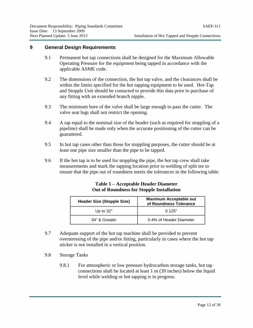
ensure that the pipe out of roundness meets the tolerances in the following table:
Table 1 – Acceptable Header Diameter
Out of Roundness for Stopple Installation
Header Size (Stopple Size) Maximum Acceptable out of Roundness Tolerance
Up to 32" 0.125"
34" & Greater 0.4% of Header Diameter
9.7 Adequate support of the hot tap machine shall be provided to prevent
overstressing of the pipe and/or fitting, particularly in cases where the hot tap
sticker is not installed in a vertical position.
9.8 Storage Tanks
9.8.1 For atmospheric or low pressure hydrocarbon storage tanks, hot tap
connections shall be located at least 1 m (39 inches) below the liquid
level while welding or hot tapping is in progress.
Document Responsibility: Piping Standards Committee SAEP-311
Issue Date: 13 September 2009
Next Planned Update: 3 June 2013 Installation of Hot Tapped and Stopple Connections
Page 13 of 30
9.8.2 If the tank is in service during the welding or hot tapping process, the
operating organization shall ensure that the liquid level above the level
of the weld or cut shall not be less than 1 meter.
9.8.3 Connections on tanks shall meet the requirements SAES-D-108.
10 Limitations on Materials
10.1 Hot tap and stopple fittings shall be procured from an approved manufacturer
per SAES-L-101.
10.2 Any Direct Charge Requisitions prepared as part of the design package for hot
tap tees, stopple split tees, or Lock-o-Ring flanges Stopple sealing elements
shall be reviewed and approved by the Hot Tap and Stopple Unit prior to issuing
for purchase.
10.3 Hot tap and stopple fittings shall comply with Saudi Aramco Materials System
Specification 02-SAMSS-006.
11 Limitations on Flow and Pressure during Hot Tapping
11.1 The Maximum flow velocities during hot tapping shall be as follows:
a) Liquid and two-phase 3.05 m/sec (10 ft/s) maximum
b) Gas 9.10 m/sec (30 ft/s) maximum.
Commentary Notes:
1) Hot tap and stipple machine manufacturers have established the above maximum flow velocity in lines during the hot tapping operation. Higher velocities may cause spinning of the coupon on the pilot drill and subsequent loss of the coupon. If higher velocities cannot be avoided, the Hot Tap & Stopple Unit should be consulted as steps can be taken to ensure that the coupon does not become detached even at higher velocities.
2) Small diameter hot taps (i.e., 2 inch and less) are normally performed with a drill which does not cut a coupon, therefore no velocity restrictions apply.
11.2 Minimum flow is not mandatory during hot tapping operation. However, in
cases where a pipeline has been cut or ingress of air has otherwise been allowed,
the air must be removed from the pipeline by either putting the line in service
with an adequate flow rate to sweep out or by other means such purging and
venting to ensure that the air is displaced from the pipeline.
Commentary Note:
When performing the coupon cutting operation for a stopple, flow in the pipeline
Document Responsibility: Piping Standards Committee SAEP-311
Issue Date: 13 September 2009
Next Planned Update: 3 June 2013 Installation of Hot Tapped and Stopple Connections
Page 14 of 30
to disperse the cuttings away from the stopple sealing area is advantageous but not essential.
12 Documentation
The appropriate forms shall be completed, distributed and documented as detailed in the
section follows.
12.1 Form 7627-ENG, "Hot Tap/Stopple & Reinforcement Calculation"
12.1.1 The Responsible Engineer shall prepare a separate Form SA
7627-ENG for each hot tap operation.
12.1.2 Each Form SA 7627-ENG shall be completed in sequence and by the
organization identified:
Form Section # Person/Organization
1 Initiating Engineer
2 Operations Engineer
3 Responsible Inspection Unit
4 Operation or Project Engineer
5 Operation or Project Engineer
12.1.3 The Responsible Engineer shall forward the form, when Sections 1, 2,
and 3 are complete, together with ultrasonic thickness measurements
(Appendix A.1 of this SAEP), to the Project Engineer or responsible
Operations Engineering Supervisor.
12.1.4 The Project Engineer or the responsible Operations Engineering
Supervisor shall perform the required calculations in accordance with
Section 13 of this procedure and shall complete Section 4 of Form SA
7627-ENG.
12.1.5 The responsible engineering shall obtain the appropriate approvals and
endorsement on Form SA 7627-ENG.
12.1.6 Drawings and specifications prepared by the responsible engineering
shall include the length, diameter, wall thickness, flange rating and
material of the new connection plus the type and dimensions of the
connection reinforcement, if required (Refer to Std. Dwg. AB-036719).
12.1.7 Welding Procedure Specifications shall be approved by the Consulting
Services Department/Welding Unit.
Document Responsibility: Piping Standards Committee SAEP-311
Issue Date: 13 September 2009
Next Planned Update: 3 June 2013 Installation of Hot Tapped and Stopple Connections
Page 15 of 30
12.1.8 After the responsible engineering group has obtained the appropriate
approvals, a record copy shall be retained in a permanent central file,
and the design package forwarded to the Responsible Engineer for
construction.
12.1.9 Once approval is obtained, the Responsible engineer shall distribute
copies of each Form SA 7627-ENG to the following personnel:
1) Operations Superintendent
2) Hot Tap and Stopple Unit
3) Operations Engineering Supervisor
4) Construction/Maintenance Installation Crew
5) Responsible Inspection Supervisor
7) Project Manager (if appropriate)
12.2 Form SA 7235-ENG "Hot Tap Data and Checklist":
12.2.1 The Responsible Engineer shall prepare and forward Form SA
7235-ENG "Hot Tap Data & Check List" to the Hot Tap and Stopple
Unit.
12.2.2 The data entered in this form must be obtained from a site inspection of
the hot tap connection.
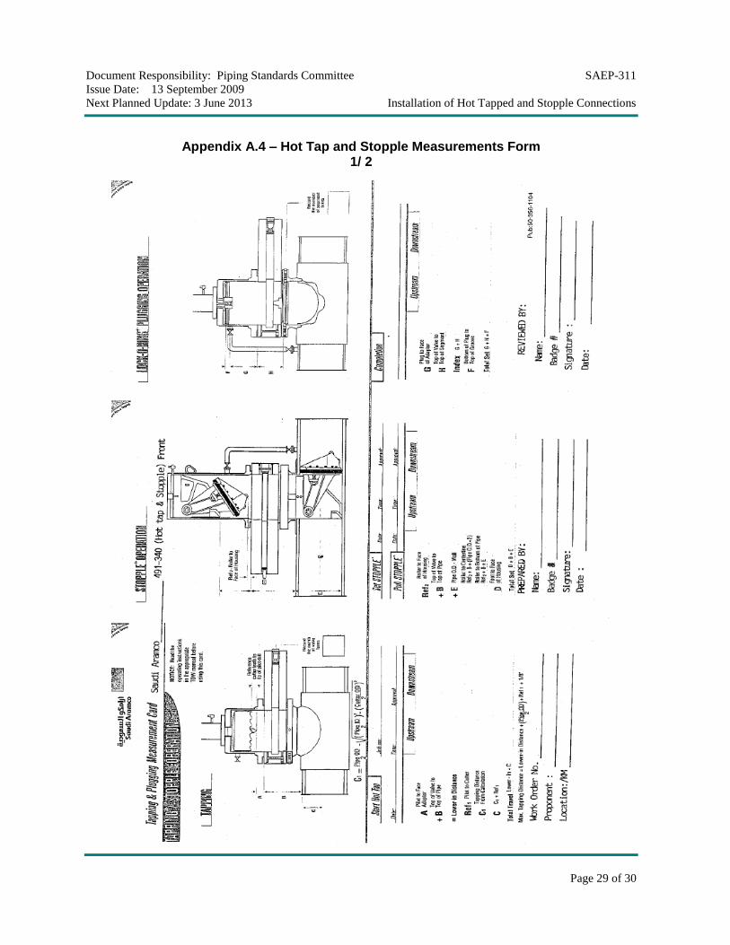
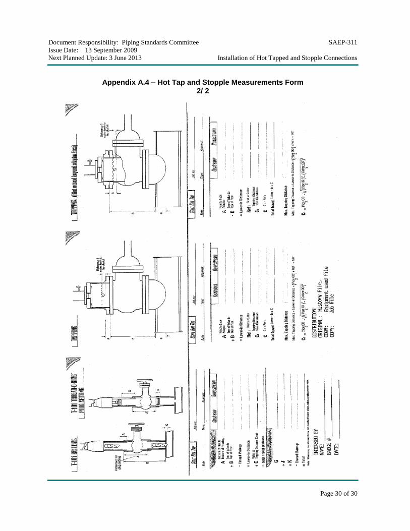
12.3 Form Hot Tap & Stopple measurement (Appendix A.4) is to be filled by Hot
Tap Unit Supervisor and approved by the Hot Tap Foreman.
12.4 Other Drawing Revisions
The Responsible Engineer is responsible for revising and updating existing
Saudi Aramco drawings, P&IDs and any other drawing affected as a result of
the hot tap installation.
13 Installation and Welding of Hot Tap and Stopple Connections
13.1 The minimum remaining wall thickness at the weld connection area shall not be
below minimum thickness, Tm, as specified on the Safety Instruction Sheet
(SIS), and in all cases, no less than 5 mm (0.2 inch).
Commentary Note:
Welding of hot tap connections on pipe containing non-hazardous material such as water at less than 150 psig and below 65°C when the wall thickness is below 5 mm (0.2 inch) may be undertaken provided the possibility of burn-through is
Document Responsibility: Piping Standards Committee SAEP-311
Issue Date: 13 September 2009
Next Planned Update: 3 June 2013 Installation of Hot Tapped and Stopple Connections
Page 16 of 30
recognized and the consequences accepted by the construction agent and proponent (this condition still requires a waiver to be processed thru CSD).
13.2 Existing welds under hot tap fittings or reinforcing pads (or sleeves) shall be
ground smooth as required to ensure acceptable fit up. This is particularly
important for stopple fittings where the outlet flange must be accurately centered
on the pipe and a projecting weld would prevent this. If possible, the hot tap
location should be selected such that no welds are located under the area to be
cut by the hot tap cutter.
13.3 For hardenable or high strength steels and for piping where pipe or fitting wall
thickness requires preheat per the applicable ASME code, the Consulting
Services Department shall be contacted for welding procedure approval.
13.4 Welding on Pipelines under Pressure
13.4.1 The form SA 7627-ENG shall specify the maximum internal pressure
in the pipeline. The pressure in the pipe during welding shall not
exceed that calculated by the following formula:
Pmax = OD
0.72 0.10)2S(t (1)
Where:
Pmax = Maximum operating pressure of the pipeline during
welding, psig
S = Specified minimum yield strength of the pipe, psi
t = Minimum measured wall thickness of the pipe at the
weld area, inches.
OD = Outside diameter of the pipe, inches.
Commentary Notes:
1. The minus 0.10 inch wall thickness takes into account the molten and heat affected portion of the base metal which does not contribute to pressure containment.
2. For in-plant piping designed to ASME B31.3, replace S and F in the formula with the allowable stress in Table A-1 of ASME B31.3.
To ensure the wall thickness is thoroughly measured, a continuous UT
scan shall be conducted around the circumference of the pipe weld
areas.
Document Responsibility: Piping Standards Committee SAEP-311
Issue Date: 13 September 2009
Next Planned Update: 3 June 2013 Installation of Hot Tapped and Stopple Connections
Page 17 of 30
13.4.2 In cases where a pipeline has been cut or ingress of air has otherwise
been allowed, the air must be removed from the pipeline before
welding can be performed. One method of removing the air is by
putting the line in service with an adequate flow rate to sweep out or
by other means such as purging and venting to ensure that the air is
displaced from the pipeline. Once this has been achieved, welding can
proceed with or without flow.
14 Pressure Testing and Inspection
14.1 The Responsible Engineer shall ensure that the hot tapping equipment, the hot
tap valve and branch connection have been pressure tested in accordance with
this SAEP prior to commencing the actual hot tap operation.
14.2 The appropriate Inspection Representative shall witness and approve all
hydrostatic testing required for completion of the hot tap connection.
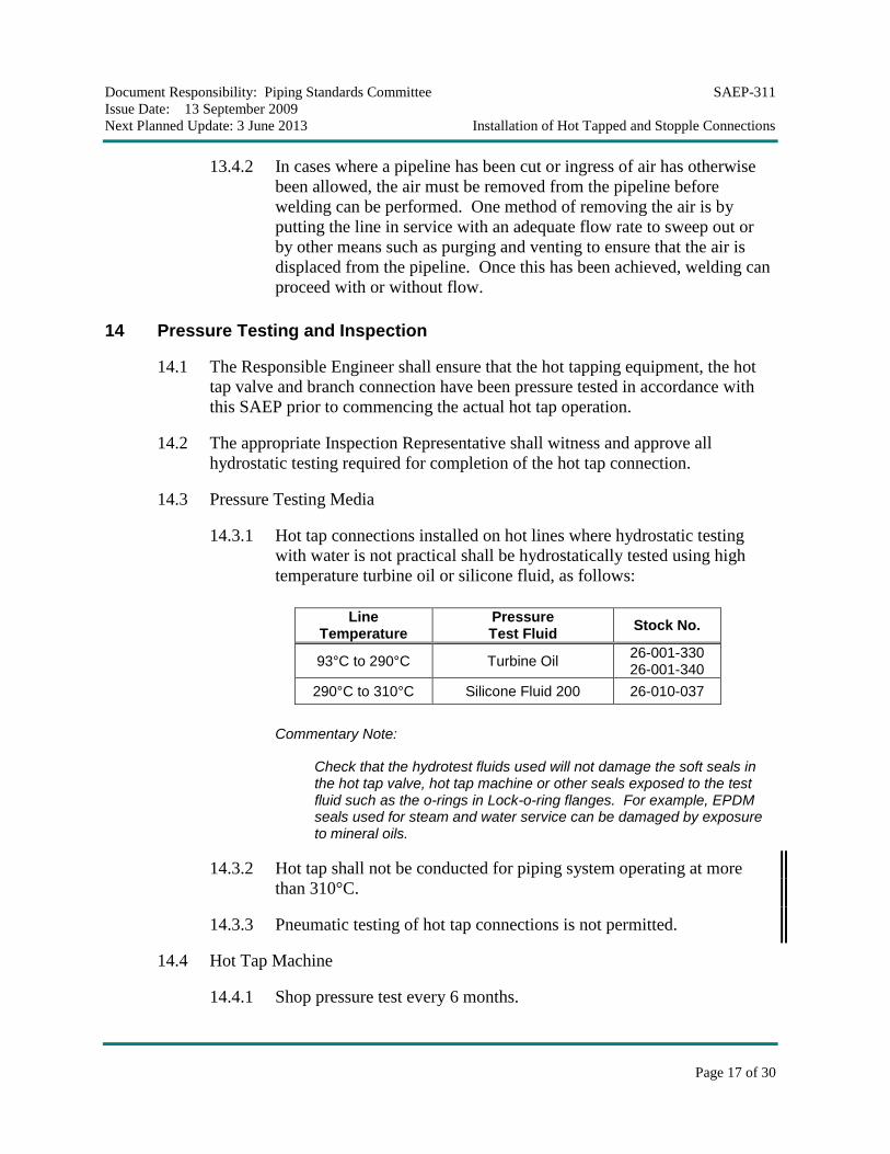
14.3 Pressure Testing Media
14.3.1 Hot tap connections installed on hot lines where hydrostatic testing
with water is not practical shall be hydrostatically tested using high
temperature turbine oil or silicone fluid, as follows:
Line Temperature
Pressure Test Fluid
Stock No.
93°C to 290°C Turbine Oil 26-001-330 26-001-340
290°C to 310°C Silicone Fluid 200 26-010-037
Commentary Note:
Check that the hydrotest fluids used will not damage the soft seals in the hot tap valve, hot tap machine or other seals exposed to the test fluid such as the o-rings in Lock-o-ring flanges. For example, EPDM seals used for steam and water service can be damaged by exposure to mineral oils.
14.3.2 Hot tap shall not be conducted for piping system operating at more
than 310°C.
14.3.3 Pneumatic testing of hot tap connections is not permitted.
14.4 Hot Tap Machine
14.4.1 Shop pressure test every 6 months.
Document Responsibility: Piping Standards Committee SAEP-311
Issue Date: 13 September 2009
Next Planned Update: 3 June 2013 Installation of Hot Tapped and Stopple Connections
Page 18 of 30
14.4.2 Replace the boring bar and retaining rod main seals and hydrotest after
the machine has been used on sour or highly corrosive fluids.
14.4.3 Replace the boring bar and retaining rod main seals and hydrotest after it
has been used on lines with operating temperatures in excess of 150°C.
14.4.4 A stamped brass tag/stencil shall be affixed to the hot tap and stopple
equipments machine indicating the test pressure, maximum operating
pressure and overhaul date.
14.4.5 The pressure testing of the hot tap machine, will take place in the shop
after the machine has been checked and worn parts replaced.
14.5 Hot Tap and Stopple Adaptors
All adaptors shall be marked with their maximum operating pressure and test
pressure. They must be visually inspected for corrosion or mechanical damage
before use and shall be inspected by MPI or hydrotested every five years.
14.6 Hot Tap Valve
14.6.1 A body and high pressure seat test (on both sides) shall be performed
in the shop on all hot tap valves prior to installation.
14.6.2 Resilient (soft) seat valves shall have zero leakage.
14.6.3 Valves with metal to metal seats shall meet the leakage criteria of
API STD 598, Valve Inspection and Testing.
14.6.4 A tag shall be attached to the valve indicating test date and test
pressure.
Commentary Note:
Sandwich valves only require the body test and a test of the seat on the hot tap machine side of the valve.
14.6.5 The seat of the hot tap valve shall be leak tested after installation by
applying pressure through the branch connection boss. The test
pressure shall be the expected line pressure during hot tapping plus
10%.
Commentary Note:
This valve seat test cannot be performed when hot tapping a weld boss because there is no room for the test connection. In this case, the hot tap valve will be seat tested on site immediately prior to installation.
Document Responsibility: Piping Standards Committee SAEP-311
Issue Date: 13 September 2009
Next Planned Update: 3 June 2013 Installation of Hot Tapped and Stopple Connections
Page 19 of 30
14.7 Stopple Equipment
14.7.1 Stopple heads shall be disassembled and all components including
bolts inspected by magnetic particle or dye penetrant for cracks
subsequent to any use in sour service.
14.7.2 Stopple heads shall be pressure tested for the following conditions:
a) Every five years.
b) When the nose piece screws and/or the pin yoke is replaced.
c) When the stopple head is modified.
14.7.3 The lip seal on the back of the sealing element shall be cut to ensure
that the test pressure is exerted over the full area of the nose piece
which will be the worst case scenario during actual usage.
14.7.4 The length of each of the nose piece bolts must be measured with a
micrometer before and after the pressure test to ensure that yielding has
not occurred.
14.7.5 An increase in bolt length will indicate that the test pressure and hence
design pressure is incorrect or the bolt tightening torque is too high.
14.7.6 The nose piece bolts shall be tested by magnetic particle inspection or
dye penetrant subsequent to the pressure test.
14.7.7 Stopple cylinders shall be pressure tested once a year.
14.8 Hot Tap Connections
14.8.1 For field fabricated branch connections (non-factory made split tees),
the branch connection shall be pressure tested prior to installing the
reinforcing pad or full encirclement reinforcement.
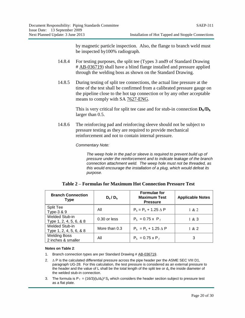
14.8.2 The test pressure of the branch connection shall comply with
SAES-L-150 requirements and shall not exceed the maximum pressure
per Table-2 below "Hot Connection Pressure Test Formulas".
Table-2 utilizes with modification the results of PRCI Report # 175,
"Proof Testing of the Pre-Hot-Tap Branch Connection".
14.8.3 In case that the calculated branch test pressure is less than the piping
system test pressure, all welds of the pressure containing branch
connection, longitudinal and circumferential welds, must be inspected
Document Responsibility: Piping Standards Committee SAEP-311
Issue Date: 13 September 2009
Next Planned Update: 3 June 2013 Installation of Hot Tapped and Stopple Connections
Page 20 of 30
by magnetic particle inspection. Also, the flange to branch weld must
be inspected by100% radiograph.
14.8.4 For testing purposes, the split tee (Types 3 and9 of Standard Drawing
# AB-036719) shall have a blind flange installed and pressure applied
through the welding boss as shown on the Standard Drawing.
14.8.5 During testing of split tee connections, the actual line pressure at the
time of the test shall be confirmed from a calibrated pressure gauge on
the pipeline close to the hot tap connection or by any other acceptable
means to comply with SA 7627-ENG.
This is very critical for split tee case and for stub-in connection Db/Dh
larger than 0.5.
14.8.6 The reinforcing pad and reinforcing sleeve should not be subject to
pressure testing as they are required to provide mechanical
reinforcement and not to contain internal pressure.
Commentary Note:
The weep hole in the pad or sleeve is required to prevent build up of pressure under the reinforcement and to indicate leakage of the branch connection attachment weld. The weep hole must not be threaded, as this would encourage the installation of a plug, which would defeat its purpose.
Table 2 – Formulas for Maximum Hot Connection Pressure Test
Branch Connection Type
Db / Dh Formulae for
Maximum Test Pressure
Applicable Notes
Split Tee Type-3 & 9
All Pb = Ph + 1.25 P
Welded Stub-in Type 1, 2, 4, 5, 6, & 8
0.30 or less Pb = 0.75 x P f 3
Welded Stub-in Type 1, 2, 4, 5, 6, & 8
More than 0.3 Pb = Ph + 1.25 P 2
Welding Boss 2 inches & smaller
All Pb = 0.75 x P f 3
Notes on Table 2:
1. Branch connection types are per Standard Drawing # AB-036719.
2. P is the calculated differential pressure across the pipe header per the ASME SEC VIII D1, paragraph UG-28. For this calculation, the test pressure is considered as an external pressure to the header and the value of L shall be the total length of the split tee or db the inside diameter of
the welded stub-in connection.
3. The formula is P f = (16/3)(th/db)² Sy which considers the header section subject to pressure test as a flat plate.
Document Responsibility: Piping Standards Committee SAEP-311
Issue Date: 13 September 2009
Next Planned Update: 3 June 2013 Installation of Hot Tapped and Stopple Connections
Page 21 of 30
Commentary Note:
A 0.75 factor has been introduce to insure that section will not be subject to yield. The formula gives very high pressure for testing compared to others for small branch connections.
4. Nomenclatures used in the table:
P : The calculated differential pressure across the pipe header per the ASME SEC VIII D1, UG-28
Dh : Header outside diameter
Db : Branch outside diameter
db : Branch inside diameter
th : Header pipe wall thickness
tb : Branch pipe wall thickness
Ph : Header pipe pressure
Pb : Branch pipe test pressure
Pf : Pressure for flat plate = (16/3)(th/db)² Sy
Sy : SMYS of header pipe material
Commentary Notes on Table 2:
PRC Report # 175 "Proof Testing of the Pre-Hot-Tap Branch Connection", 1989 contains detailed analysis of stress level in the hot tap joints under pressure testing.
14.9 Final Hot Tap Assembly Testing
14.9.1 After installation of the hot tap machine, a final leak test of the entire
assembly shall be made with the hot tap valve in the open position by
applying pressure through the branch connection boss. The test pressure
shall be the expected line pressure during hot tapping plus 10%.
14.9.2 After completion of the above tests, a bar stock plug shall be installed
in the branch connection boss and seal welded.
15 Stoppling
15.1 General Notes
15.1.1 Stopples should be inserted in pipelines with no flow at the stopple
location.
Commentary Note:
Stopple plugging heads can only withstand a differential pressure once they are fully inserted in the pipeline. If any significant differential pressure develops before full insertion is achieved, the stopple insertion equipment will be damaged and it may be impossible to retract the stopple head. The no flow condition is normally achieved on pipelines in
Document Responsibility: Piping Standards Committee SAEP-311
Issue Date: 13 September 2009
Next Planned Update: 3 June 2013 Installation of Hot Tapped and Stopple Connections
Page 22 of 30
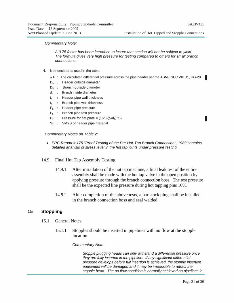
service by diverting flow through a full flow bypass. Figure 15.1 shows a typical example of inserting the stopple with no flow condition.
STOPPLE
VALVE
Close valve before stopple insertion
equalizing connection.open during insertion.
Figure 15.1 – Typical Example of Inserting
the Stopple with no Flow Condition
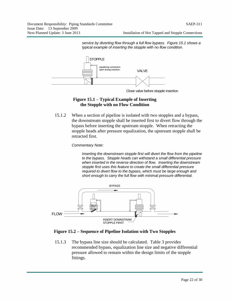
15.1.2 When a section of pipeline is isolated with two stopples and a bypass,
the downstream stopple shall be inserted first to divert flow through the
bypass before inserting the upstream stopple. When retracting the
stopple heads after pressure equalization, the upstream stopple shall be
retracted first.
Commentary Note:
Inserting the downstream stopple first will divert the flow from the pipeline to the bypass. Stopple heads can withstand a small differential pressure when inserted in the reverse direction of flow. Inserting the downstream stopple first uses this feature to create the small differential pressure required to divert flow to the bypass, which must be large enough and short enough to carry the full flow with minimal pressure differential.
FLOW
INSERT DOWNSTRAM STOPPLE FIRST
BYPASS
Figure 15.2 – Sequence of Pipeline Isolation with Two Stopples
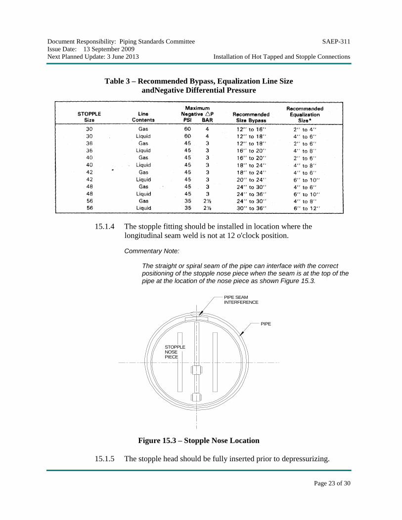
15.1.3 The bypass line size should be calculated. Table 3 provides
recommended bypass, equalization line size and negative differential
pressure allowed to remain within the design limits of the stopple
fittings.
Document Responsibility: Piping Standards Committee SAEP-311
Issue Date: 13 September 2009
Next Planned Update: 3 June 2013 Installation of Hot Tapped and Stopple Connections
Page 23 of 30
Table 3 – Recommended Bypass, Equalization Line Size
andNegative Differential Pressure
15.1.4 The stopple fitting should be installed in location where the
longitudinal seam weld is not at 12 o'clock position.
Commentary Note:
The straight or spiral seam of the pipe can interface with the correct positioning of the stopple nose piece when the seam is at the top of the pipe at the location of the nose piece as shown Figure 15.3.
PIPE
STOPPLE NOSE PIECE
PIPE SEAM INTERFERENCE
Figure 15.3 – Stopple Nose Location
15.1.5 The stopple head should be fully inserted prior to depressurizing.
Document Responsibility: Piping Standards Committee SAEP-311
Issue Date: 13 September 2009
Next Planned Update: 3 June 2013 Installation of Hot Tapped and Stopple Connections
Page 24 of 30
Commentary Note:
Stopple is locked in position when a differential pressure is applied across the sealing element. Without this differential pressure, the line pressure can exert sufficient force on the insertion equipment to cause the stopple head to retract.
15.1.6 Stopples cannot be guaranteed to seal 100%. A small amount of
leakage should be expected. The design package detailing the
activities preceding the stopple isolation shall detail all safety
measures. The following requirements shall be addressed as a
minimum in the design package:
15.1.6.1 It is mandatory to measure the amount of leakage in the
isolated section.
15.1.6.2 It is mandatory to continuously purge the isolated section
with nitrogen during the cold cut. A second isolation with a
bleed may be needed based on the leakage rate.
15.1.6.3 Before conducting any hot work, it is mandatory to install
second isolation or barrier with a bleed connection for
combustible or hazardous product. The second isolation
could be a balloon, mud pack, sealing scraper, mechanical
plug, or similar device. For the bleed size, SAEP-310 can
be used as guideline.
Commentary Note:
A new OIM "Isolate a Section of a Live Hydrocarbon Pipeline for Section Removal" being developed.
15.2 The maintenance/modification work shall be completed immediately as the
pipelines shall not be left on operation against the stopple with an open end or to
weld flange and blinded till work is ready for the final tie in.
Revision Summary
3 June 2008 Major revision. 13 September 2009 Minor revision.
Document Responsibility: Piping Standards Committee SAEP-311
Issue Date: 13 September 2009
Next Planned Update: 3 June 2013 Installation of Hot Tapped and Stopple Connections
Page 25 of 30
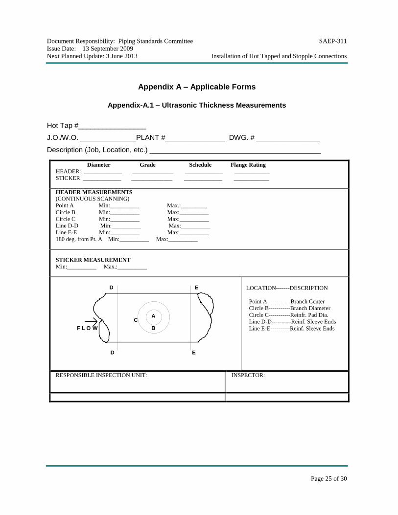
Appendix A – Applicable Forms
Appendix-A.1 – Ultrasonic Thickness Measurements
Hot Tap #_________________
J.O./W.O. ______________PLANT #_______________ DWG. # ________________
Description (Job, Location, etc.) ___________________________________________
Diameter Grade Schedule Flange Rating HEADER: _____________ ______________ _____________ ____________
STICKER _____________ ______________ _____________ ____________
HEADER MEASUREMENTS (CONTINUOUS SCANNING)
Point A Min:__________ Max.:_________
Circle B Min:__________ Max:__________
Circle C Min:__________ Max:__________
Line D-D Min:__________ Max:__________
Line E-E Min:__________ Max:__________
180 deg. from Pt. A Min:__________ Max:__________
STICKER MEASUREMENT Min:__________ Max.:__________
CA
B
ED
F L O W
D E
LOCATION-------DESCRIPTION
Point A------------Branch Center
Circle B-----------Branch Diameter
Circle C-----------Reinfr. Pad Dia.
Line D-D----------Reinf. Sleeve Ends
Line E-E----------Reinf. Sleeve Ends
RESPONSIBLE INSPECTION UNIT:
INSPECTOR:
Document Responsibility: Piping Standards Committee SAEP-311
Issue Date: 13 September 2009
Next Planned Update: 3 June 2013 Installation of Hot Tapped and Stopple Connections
Page 26 of 30
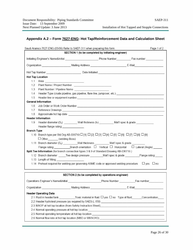
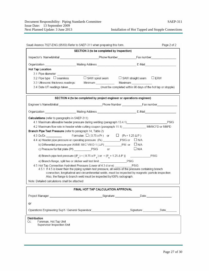
Appendix A.2 – Form 7627-ENG: Hot Tap/Reinforcement Data and Calculation Sheet
Document Responsibility: Piping Standards Committee SAEP-311
Issue Date: 13 September 2009
Next Planned Update: 3 June 2013 Installation of Hot Tapped and Stopple Connections
Page 27 of 30
Document Responsibility: Piping Standards Committee SAEP-311
Issue Date: 13 September 2009
Next Planned Update: 3 June 2013 Installation of Hot Tapped and Stopple Connections
Page 28 of 30
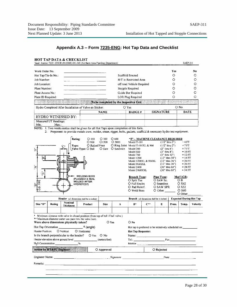
Appendix A.3 – Form 7235-ENG: Hot Tap Data and Checklist
Document Responsibility: Piping Standards Committee SAEP-311
Issue Date: 13 September 2009
Next Planned Update: 3 June 2013 Installation of Hot Tapped and Stopple Connections
Page 29 of 30
Appendix A.4 – Hot Tap and Stopple Measurements Form 1/ 2
Document Responsibility: Piping Standards Committee SAEP-311
Issue Date: 13 September 2009
Next Planned Update: 3 June 2013 Installation of Hot Tapped and Stopple Connections
Page 30 of 30
Appendix A.4 – Hot Tap and Stopple Measurements Form 2/ 2