Copper Production Technology
47
Chapter 6 Copper Production Technology
Transcript of Copper Production Technology

Chapter 6
Copper Production Technology

CONTENTSPage
H i s t o r y . . . . . . . . . . . . . . . . . . . . . . . . . . . . . 1 0 3Explorat ion . . . . . . . . . . . . . . . . . . . . . . . . . .113Mining . . . . . . . . . . . . . . . . ..............116Comminution and Separation . . . . . . .. ...127Beneficiation. . . . . . . . . . . . . . . . . . ...; ...130P y r o m e t a l l u r g y . . . $ . . . . . . . . . . . . . . . . . . . 1 3 3H y d r o m e t a l l u r g y . . . . . . . . . . . . . . . . . . . . . 1 4 0Elec t rometa l lu rgy . . . . . . . . . . . . . . . . . . . . .142Mel t ing and Cast ing . . . . . . . . . . . . . . . . . . .145
BoxesBox Page6-A.The Lakeshore Mine in Situ Project ..1266-B. Smelting Furnaces . . . . .
Figure
6-1.
6-2.6-3.
6-4.
6-5.
6-6.
6-7.6-8.
6-9.6-10.6-11.
6-12.6-13.
Figures
Flow Sheets for CopperProduction . . . . . . . . . . .
. . . . . . . . . . . 136
Page
. . . . . . . . . . . 104Early Smelting Technology. . .......107Early Copper-Producing AreasofEurope and the Middle East . ......108Copper Deposits of NorthernM i c h i g a n . . . . . . . . . . . . . . . . . . . . . . . 1 0 9Copper Production Areas of theNorthern and Central RockyMountains . . . . . . ................112Copper Production Areas of theS o u t h w e s t . . . . . . . . . . . . . . . . . . . . . . 1 1 2Sample Geologic Map . ...........114Model of Hydrothermal AlterationZones Associated With PorphyryCopper Deposits . . . . . . . . . . .......115Stages of Mineral Exploration .. ....116Underground Mining Terms . ......119Two Underground MiningMethods . . . . . . . . . . . . . . . . . ... ...12OOpen Pit Mining Terms . ..........121Heap and Dump Leaching . .......123
Figure6-14.6-15.6-16.6-17.6-18.6-19.6-20.
6-21.6-22.6-23,6-24.6-25.6-26.6-27.
6-28.6-29.6-30.6-31.
Table
PageTypes of in Situ Leaching Systems ..124Jaw Crusher . . . . . . ...............127Hydrocyclone, . . . . . . . . . . . . . . . . . .129Flotat ion Cel ls . . . . . . . . . . . . . . . . . . .130Flowsheets for Copper Flotation ....132C o l u m n C e i l . . . . . . . . . . . . . . . . . . . . 1 3 3Development of SmeltingTechnology Compared with WorldCopper Production . . . . . . . . . . . . . . .135Reverberatory Furnace . . . . . . . . ....136Electr ic Furnace . . . . . . . . . . . . . . . . .137INCO Flash Furnace . . . . . . . . .. ....138Outokumpu Flash Furnace . .......138Pierce-Smith Converter ... ... ... ..139Noranda Reactor . . . . . . . . . . . . . . . .139Mitsubishi Continuous SmeltingSystem . . . . . . . . . ................140Kennecott Cone Precipitator . ......142Flowsheet for Solvent Extraction ....143Continuous Casting Wheel . .......146Continuous Rod Rolling Mill ., ....,147
TablesPage
6-1.
6-2.
6-3.6-4.
6-5.
6-6.
6-7,
6-8.
Summary of PyrometallurgicalProcesses . . . . . . . .................105Summary of HydrometallurgicalProcesses . . . . . . . .................106Major U.S. Copper Mines . .........110Remote Sensing Systems and ImageTypes for Mineral Exploration . ......117Considerations in Choice of MiningM e t h o d . . . . . . . . . . . . . . . . . . . . . . . . . 1 1 8Characteristics of Solution MiningT e c h n i q u e s . . . . . . . . . . . . . . . . . . . . . . 1 2 2Summary of in Situ Copper MiningA c t i v i t i e s . . . . . . . . . . . . . . . . . . . . . . . . 1 2 5Smelter Technology in theUnited States . . . . . . . . . . . ..........138

Chapter 6
Copper Production Technology
The last boom in technological innovation for
the copper industry occurred in the f irst two dec-
ades of this century, when open pit mining, flo-tation concentration, and the reverberatorysmelter were adapted to porphyry copper ores.With the exception of leaching-solvent extrac-tion-electrowinning, the basic methods of cop-per production have remained unchanged for 65years. Moreover, six of the mines opened be-tween 1900 and 1920 are still among the majorcopper producers in the United States today.
Instead of great leaps forward, technologicalinnovation in the copper industry in the last 65years has consisted largely of incrementalchanges that allowed companies to exploit lowergrade ores and continually reduce the costs ofproduction. Economies of scale have been real-ized in all phases of copper production. Both ma-chine and human productivity have increaseddramatically.
This chapter briefly describes the technologyfor producing copper, from exploration, throughmining and milling, to smelting and refining orsolvent extraction and electrowinning. The chap-ter begins with an overview of the history of cop-per technology development. Then, for eachstage i n copper production, it reviews the cur-rent state-of-the-art, identifies recent technologi-cal advances, reviews probable future advancesand research and development needs, and dis-cusses the importance of further advances to thecompetitiveness of the U.S. industry. Figure 6-1shows flow-sheets for pyrometallurgical’ andhydrometa l lurg ica l 2 copper production. Tables6-1 and 6-2 provide capsule summaries of theseprocesses.
1 PyrometaIIurgy IS the extractIon of metaI from ores anD concen-
trates using chemical reactions at high temperatures.2 Hydrometallurgy is the recovery of metaIs from ores using water-
based solutions.
As early as 6000 B. C., native copper–the puremetal—was found as reddish stones in the Med-iterranean area and hammered into utensils,weapons, and tools. Around 5000 B. C., artisansdiscovered that heat made copper more malle-able. Casting and smelting of copper beganaround 4000-3500 B.C. (see figure 6-2). About2500 B. C., copper was combined with tin tomake bronze—an alloy that allowed strongerweapons and tools. Brass, an alloy of copper andzinc, probably was not developed until 300 A.D.
Copper was first mined (as opposed to foundon the ground) in the Timna Valley in Israel—adesolate area believed to be the site of King Solo-mon’s Mines (see figure 6-3). The Phoeniciansand Remans, who worked the great mines onCyprus and in the Rio Tinto area of southernSpain, made the early advances in copper explo-ration and mining methods. For example, the Ro-mans found nearly 100 lens-shaped ore bodies inthe Rio Tinto copper district. Modern geologists
have found only a few additional deposits, andalmost all of Rio Tinto’s modern production hasbeen from ore first discovered by the Remans.3
At Rio Tinto, the Remans mined the upper, ox-idized, part of the ore and collected the copper-Iaden solutions produced by water slowly seep-ing down through the suIfide ore bodies. Whenthe Moors conquered this part of Spain duringthe Middle Ages, the oxide ores had largely beenexhausted. Learning from the Roman experiencewith seepage, the Moors developed open pit min-ing, heap leaching, and iron precipitation tech-niques that continued to be used at Rio Tinto intothe 20th century.
In Britain, copper and tin were worked in Corn-wall and traded with the Phoenicians as early as1500 B.C. The Remans brought improved metal-lurgical techniques to Britain, and spurred devel-
3ira B. joralemon, Copper; The Encompassing Story of MankInd’s
First MetaL (Berkeley, CA: Howell-North Books, 1973).
103

104
Figure
Pyrometal lurgical
Sulfide ores(0.5-2% Cu)
I Comminution1
I I
I FIotation I
Concent rates( 2 0 - 3 0 % C u )
1
6-1.-FIow Sheets for Copper Production
Hydrometal luigical
Oxide and sulfide ores( 0 . 3 - 2 . 0 % C u )
Leaching
Pregnant Ieachate(20-50% Cu)
Precipitation Solventextract ion
IISmelting I
Cement copper1 (85-90% Cu)
Matte(50-75% Cu)
I I
I Converting i
Anode refiningand casting
I II
Anodes(99.5% Cu) I
Cathodes (99.99+% Cu)
SOURCE: Office of Technology Assessment.
opment of the mines of Cumberland and NorthWales. When the Remans left Britain early in the5th century, however, economic developmentstagnated and it was a thousand years or morebefore Britain’s metal industry was reestablished.4
In the interim, Germany became the center ofthe European copper industry, bringing a num-ber of improvements in copper mining, metal-lurgy, and fabricating.5
4Sir Ronald L. Prain, Copper: The Anatomy of an Industry (Lon-don: Mining journal Books Ltd., 1975).
‘Raymond F. Mikesell, The World Copper Industry: Structure andEconomic Analysis (Baltimore, MD: The Johns Hopkins Press, 1979).
Cathodes (99.99+% Cu)
King Henryberland and
Vlll reopened the mineselsewhere, and Britain
in Cum-became
famed for bronze casting and the manufactureof armaments. By the end of the 16th century,Britain was producing 75 percent of the world’scopper. British advances in metallurgy helped toestablish a world monopoly in smelting that con-tinued until around 1900, when foreign producersbuilt large mills and smelters that took advantageof such British inventions as the reverberatory fur-nace and froth flotation. b Moreover, the miners
6Prain, supra note 4.
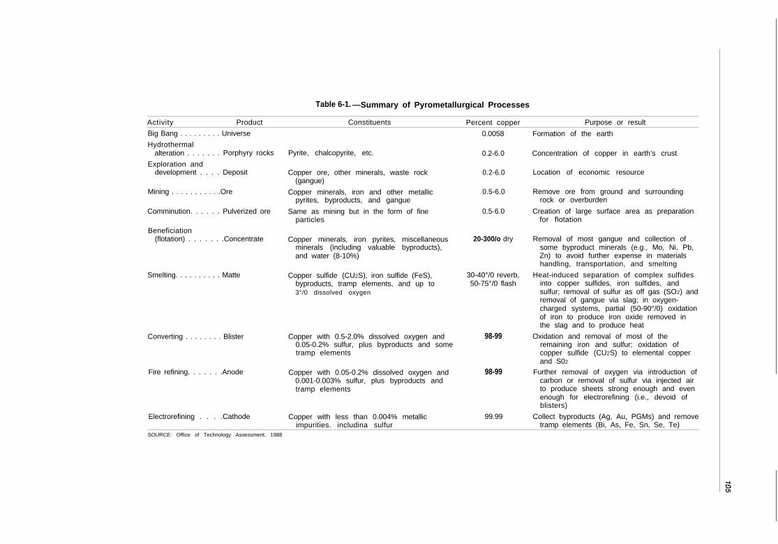
Table 6-1. —Summary of Pyrometallurgical Processes
Activity Product Constituents Percent copper Purpose or result
Big Bang . . . . . . . . . Universe
Hydrothermalalteration . . . . . . . Porphyry rocks
Exploration anddevelopment . . . . Deposit
Mining . . . . . . . . . . .Ore
Comminution. . . . . . Pulverized ore
Beneficiation(flotation) . . . . . . .Concentrate
Smelting. . . . . . . . . . Matte
Converting . . . . . . . . Blister
Fire refining. . . . . . .Anode
Electrorefining . . . .Cathode
Pyrite, chalcopyrite, etc.
Copper ore, other minerals, waste rock(gangue)
Copper minerals, iron and other metallicpyrites, byproducts, and gangue
Same as mining but in the form of fineparticles
Copper minerals, iron pyrites, miscellaneousminerals (including valuable byproducts),and water (8-10%)
Copper sulfide (CU2S), iron sulfide (FeS),byproducts, tramp elements, and up to3°/0 dissolved oxygen
Copper with 0.5-2.0% dissolved oxygen and0.05-0.2% sulfur, plus byproducts and sometramp elements
Copper with 0.05-0.2% dissolved oxygen and0.001-0.003% sulfur, plus byproducts andtramp elements
Copper with less than 0.004% metallicimpurities. includina sulfur
0.0058
0.2-6.0
0.2-6.0
0.5-6.0
0.5-6.0
20-300/o dry
30-40°/0 reverb,50-75°/0 flash
98-99
98-99
99.99
Formation of the earth
Concentration of copper in earth’s crust
Location of economic resource
Remove ore from ground and surroundingrock or overburden
Creation of large surface area as preparationfor flotation
Removal of most gangue and collection ofsome byproduct minerals (e.g., Mo, Ni, Pb,Zn) to avoid further expense in materialshandling, transportation, and smelting
Heat-induced separation of complex sulfidesinto copper sulfides, iron sulfides, andsulfur; removal of sulfur as off gas (SO2) andremoval of gangue via slag; in oxygen-charged systems, partial (50-90°/0) oxidationof iron to produce iron oxide removed inthe slag and to produce heat
Oxidation and removal of most of theremaining iron and sulfur; oxidation ofcopper sulfide (CU2S) to elemental copperand S02
Further removal of oxygen via introduction ofcarbon or removal of sulfur via injected airto produce sheets strong enough and evenenough for electrorefining (i.e., devoid ofblisters)
Collect byproducts (Ag, Au, PGMs) and removetramp elements (Bi, As, Fe, Sn, Se, Te)
SOURCE: Office of Technology Assessment, 1988
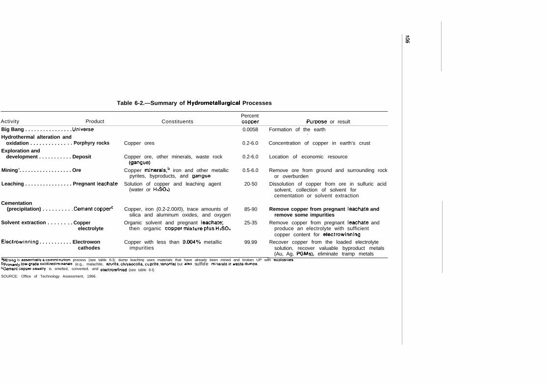
Table 6-2.—Summary of Hydrometallurgical Processes
PercentActivity Product Constituents coDDer Purt,)ose or result
Big Bang . . . . . . . . . . . . . . . .UniverseHydrothermal alteration and
oxidation . . . . . . . . . . . . . . Porphyry rocks
Exploration anddevelopment . . . . . . . . . . . Deposit
Mining a. . . . . . . . . . . . . . . . . . Ore
Leaching . . . . . . . . . . . . . . . . Pregnant Ieachate
Cementation(precipitation) . . . . . . . . . .Cement coppeti
Solvent extraction . . . . . . . . Copperelectrolyte
Electrowinning . . . . . . . . . . . Electrowoncathodes
0.0058
Copper ores 0.2-6.0
Copper ore, other minerals, waste rock 0.2-6.0(gangue)
Copper minerals,b iron and other metallic 0.5-6.0pyrites, byproducts, and gangue
Solution of copper and leaching agent 20-50(water or HAO.)
Copper, iron (0.2-2.00/0), trace amounts of 85-90silica and aluminum oxides, and oxygen
Organic solvent and pregnant Ieachate; 25-35then organic copper miXtUre plUs H2S04
Copper with less than 0.004Y0 metallic 99.99impurities
Formation of the earth.
Concentration of copper in earth’s crust
Location of economic resource
Remove ore from ground and surrounding rockor overburden
Dissolution of copper from ore in sulfuric acidsolvent, collection of solvent forcementation or solvent extraction
Remove copper from pregnant Ieachate andremove some impurities
Remove copper from pregnant Ieachate andproduce an electrolyte with sufficientcopper content for eiectrowinning
Recover copper from the loaded electrolytesolution, recover valuable byproduct metals(Au, Ag, PGMs), eliminate tramp metals
aMining is essentially a Comminution process (see table 6-l); dump leaching uses materials that have already been mined and broken UP with exdosivesbpflma~ily Iow.grade oxidized minerals (e.g., malachite, azurite, chrysocolla,-cu prite, tenorite) but also sulfide minerals in waste dumps.ccement copper usually is smelted, converted, and
SOURCE: Office of Technology Assessment, 1966.
electrorefined (see table 6-l).

107
Figure 6-2.—Early Smelting Technology
Charcoaloreflux \ m
The Egyptian copper smelting furnace was filled with amixture of copper ore, charcoal and iron ore to act as aflux. It was blown for several hours by foot or handbellows.
By the end of the smelt the copper had separated fromthe slag, which was tapped off.
SOURCE Robert Raymond, Out of tfre Fjery Furnace (University Park, PA The Pennsylvania State University Press, 1986)
and metallurgists of Cornwall, Devon, and Walesprovided much of the expertise for the early daysof the American copper industry. ’
Native Americans used native copper from theKeeweenaw Peninsula of Upper Michigan andfrom Isle Royale in Lake Superior as far back as5000 B.C. (figure 6-4). The American coloniesproduced copper beginning in 1709 in Simsbury,Connecticut. By the 1830s, U.S. production inConnecticut, New Jersey, and other States wassufficient to supply the fabricators in Boston andNew York, but the demand for finished copperand brass products was much greater than theSupply. o
Thus, the discovery of copper (and other min-eral) deposits became an important part of west-ward expansion in North America. Each ore bodyis unique, however, and finding the ore often waseasier than devising methods of economical cop-per production and transportation. Table 6-3 pro-vides a chronology of the major copper minesin the United States, and the technological ad-vances they contributed.
7Dona Id Chaput, The Cliff: Americ.? First Great Copper Mine(Kalamazoo, Ml: Sequoia Press, 1971).
81 bld .
Organized copper mine development beganlate in 1844 at Copper Harbor on the tip of theKeeweenaw Peninsula–the first regular mineshafts in the United States. The Cliff Mine, thefirst great copper mine in the Western Hemi-sphere, opened in 1845; it contributed advancedengines for hauling ore and miners out of theshafts, and for dewatering the mine. g
As the population moved West, the discoveryof copper deposits often succeeded disappoint-ing gold and silver claims. For example, miningin Butte, Montana (figure 6-5) began in the early1860s with gold, and then moved to a body ofsilver and copper ore. The stamp mills (crushers)and smelting furnaces in Butte could not sepa-rate the silver economically, however, and thecost of transporting the ore 400 miles to the rail-road was prohibitive. Butte was about to becomeanother Western ghost town, when adaptationof smelting furnaces led to a silver boom. Then,in 1881, a huge seam of rich “copper glance”(chalcocite) that ran 30 percent copper turnedButte into “the richest hill on earth. ” Railroadswere opened to Butte by the end of 1881, andit was soon a city of 40,000 with four copper

108
Figure 6Q3.— Early Copper-Producing Areas of Europe and the Middle East
smelters. By 1887, Butte had passed the Lake Su-perior Copper Country in production.lo
As in Montana, gold and silver mining in theSouthwest paled into insignificance with the dis-covery and development of rich copper depos-
IOJoralemon, supra note s.
its. Also similar to Butte, profitable developmentof the southwestern deposits depended on con-struction of railways to transport the copper tofabricators, and on processing and smelting tech-niques that cou Id economically handle the vari-ous grades and types of ore found, which in-cluded carbonates, oxides, sulfides, and silicates.A third factor was the amount of capital needed

109
Figure 6-4.—Copper Deposits of Northern Michigan
‘Ma’que”e” ‘we—/ / / I Schoolcraft .
‘“ I / / I ndta= I zManistique
J-+”- ,
Green Bay ~’ ‘ “Lake Michigan
.
The thin band of the Keweenaw copper range shoots UP through the peninsula, then goes beneath Lake Superior. IsleRoyale is in the same geological formation.
SOURCE: Donald Chaput, The Cliff: Arrrerica’s Ffrst Great Copper Mine (Kalamazoo, Ml: Sequoia Press, 1971).
to develop an ore body into a producing mine ure 6-6). Processing and smelting methods usu -and provide the necessary infrastructure to ex- ally had to be tailored to each ore body or dis-ploit it. trict. For example, in the ear ly 1880s the
mass-produced Rankin & Brayton water-jacketThe Southern Pacific Railroad was completed furnace revolutionized the smelting of oxide ores
across Arizona in 1882, and lines eventually were from the Bisbee district of Arizona. This furnaceextended to the various mining districts (see fig- could be shipped as a complete unit, requiring

110
ao
c2
~g IOmsm-ml
c2’.-8
a <
a:lu~NCO“= o .!!a.? ~~-aoc-.= --- @a)EuC L , I ~
U)21
cmcoN. =
azo0 .
%’a
co.-3“s(nc
w>.-Ij
Inz
mcmOcNo. =
<:
- - -VW-C(D:6z:
mlcoN.-
20-.-a
a)-5m
(cl
<z
<z
. .. .. .. .. .
. . .. . .. . .. . .. . .
. . .. . .. . .. . .. . .
.7s-

Table 6“3.-Major U.S. Copper Mines—Continued
Year Year.
Ore grade Mineopened closed Name Location Owner and tYDe tYDe
1940 . . active Bagdad Bagdad, Ar izona1942 . active Clay/Morenci Morenci, Ar izona1950 . . . . . active San Manuel San Manuel, Arizona1954 . . . . . 7984 Silver Bell Silver Bell, Arizona1 9 5 5 . . . , 1 9 7 4 Lavender Pit Bisbee, Ar izona955 . . . . .957 . . . . .959 . . . . .988 . . . . .962 . . . . .963 . . . . .986 . . . . .964 . . . . .
active White Pine White Pine, Michiganactive Pima Sahuarita, Arizona1985 Twin Buttes Sahuarita, Arizona
activeactive Mission Sahuarita, Arizona1983 Butte Butte, Montana
activeNA Ithaca Peak Mineral Park, Arizona
1969 . . . . . active1970 . . . . . active
1972 . . . . . 19841973 . . . . . active1974 . . . . . active1974 . . . . . leaching1974 . . . . . active1975 . . . . . 19861978 . . . active1986 . . . . . active
TyroneSierrita
SacatonSan XavierMetcalfLake ShorePinto ValleyJohnsonEisenhowerSan Manuel
Tyrone, New MexicoSahuarita. Arizona
Casa Grande, ArizonaSahuarita, ArizonaMorenci, ArizonaCasa Grande, ArizonaMiami, ArizonaBenson, ArizonaSahuarita, ArizonaSan Manuel, Arizona
Cyprus MinesPhelps DodgeMagma Copper Co.AsarcoPhelps DodgeCopper Range Co.Cyprus MinesAnaconda, then Anamax,
then CyprusAsarcoAnaconda Minerals,
then Montana ResourcesDuvalPhelps DodgeDuval, then Cyprus
AsarcoAsarcoPhelps DodgeHecla, then Noranda, then CyprusCities Service, then MagmaCyprusAnamax, then AsarcoMagma
f).5°/o —sulfides0.70/0—sulfides0.6-0.70/. —sulfides4-6Y0 —sulfides
1 YO —sulfides0.50/O—sulfides0.920/0—sulfides0.730/0—oxidessulfides
0.70/o—sulfides0.3%-sulf ides
sulfidessulfides0.80A—sulfides10\O —oxides0.460/0—sulfides0.40/0sulfidesoxides
OPOPUGOPOPUGOPOP
OPOP
OPOPOP
OP & UGOPOPUGOPOPOPOP
Technologica l advances a
First solvent extractionelectrowinning plant (1976)
First in-pit crushing andconveying system
NA indicates the actual date of closing or incorporation into open pit mining is unknown.aDates indicate first use in the U.S. unless otherwise ind!cated.bMinor amounts of production continued under various owners until around Iws.cf.JurnerOus other shafts were opened in Blsbee between 1877 and 1 gf)o, most of which were subsequently purchased by Pheips Dodge and managed Jointly with the copper Queen.
SOURCE Office of Technology Assessment, 1988

112
Figure 6-5.—Copper Production Areas of theNorthern and Central Rocky Mountains
MontanaCoeur
StlOup
Idaho Wyoming
Uwl Colorado
SOURCE: Off Ice of Technology Assessment, 1988.
Figure 6.6.—Copper Production Areasof the Southwest
+Arizona I New Maxioo
(310ba clm?w
D o u g l a s —
SOURCE. Office of Technology Assessment, 1988.
few onsite engineering skills; it had improved fueleconomy, important in the lightly forested moun-tains of southeastern Arizona; and it required nofire brick in its construction, which saved on ship-ping costs. ’ 1
Further developments in mining and process-ing technology followed the gradual decline inore grades.lz By the late 1800s, the copper ore
I I Lynn R. Bai Icy, B/sbee: Queen ot the Copper C.?mps (Tucson,
AZ: Westernlore Press, 1983).12The Importance of ore grades for mine economics and com-
petitiveness IS discussed in ch. 5,
grade in the Clifton-Morenci District of Arizonahad declined to only 4 to 5 percent copper–toolean to be smelted directly at a profit. James Col-quhoun devised a means of concentrating the orebased on techniques used to process Coloradogold ores. For some leaner oxide ores that couldnot be processed this way, Colquhoun workedout a process for dissolving the copper in sulfuricacid and precipitating it on iron. This first U.S.leaching plant was built in 1892.13
The adaptation of Colquhoun’s techniques todeposits of low-grade porphyry ores was pi-oneered at Bingham Canyon in Utah, where goldand silver miners had found an unusually largemass of copper porphyry ore. But the ore grade,then estimated to average 2.22 percent copper,was too low to be exploited economically withtraditional mining and smelting methods.ld TheUtah Copper Company’s engineer, Daniel jack-iing, determined that economies of scale werethe key to making Colquhoun’s concentrationtechniques economical with such low-grade ore.The Utah Copper Company’s 50()@ton-per-daymill at Bingham Canyon began commercial pro-duction in 1907. Utah Copper made it even moreprofitable by introducing open-pit mining withsteam shovels .15
Economies of scale in smelting also were real-ized in the early 1900s. Phelps Dodge had beenhaving problems with the Copper Queen smelterin Bisbee as the mine went deeper and the cop-per carbonate and oxide graded into sulfide ore.An entirely new smelter was built 25 miles southof Bisbee, at a site named after James Douglas,head of Phelps Dodge’s Bisbee operations. Themost modern smelter of its time, it had five fur-naces with a capacity of 5000 tons/day. lb PhelpsDodge closed the Douglas smelter in 1987 be-cause bringing it into compliance with air qual-ity regulations would have been too costly.
As soon as jackling showed that the low-gradeporphyrins could be mined profitably, they be-came the focus of exploration and development.
I ~Joralemon, supra note 3.I ~The changes i n ore grade over time, and their effects on the
estimated resources in an ore body, are discussed in ch. 5, box 5-A.I 5)oralemon, supra note 3.IGBailey, supra note 11.
113
The Nevada Consolidated Company began pro-duction in Ely, Nevada in 1908. The LewisohnBrothers partnership, which owned the OldDominion Mine at Globe, Arizona, opened a por-phyry mine at nearby Miami, Arizona in 1911.The Utah Copper Company opened Ray Minesin Arizona and Chino Mines in New Mexico in1911. Phelps Dodge acquired claims and starteddevelopment work at Tyrone, New Mexico, dur-i ng the same period. 17 Most of these porphyrinsare still among the major producing ore bodiesin the United States today.
Not all of the porphyry ores were amenable tojackling’s methods, however. For instance, avail-able milling techniques could not recover enoughof the 2.5 percent ore at the Inspiration Com-pany’s claims near Miami, Arizona. When Ana-conda purchased these claims, their consultingengineer, L.D. Ricketts, expanded on Colqu-houn’s and Jackling’s work plus developmentsin Britain, and built the first flotation plant for cop-per in the United States.18 Similarly, profitable de-
1 TPraln, supra note 4.
18A zinc flotatlon plant had been built in Butte in 1912.
velopment of the 30 million tons of 1.5 percentcarbonate ore at Ajo, Arizona was questionableuntil Ricketts developed a process of leachingwith sulfuric acid that would produce copperfrom Ajo ore for 8.5 cents/lb (the current selling
price was 14 cents/lb) .19
Phelps Dodge further refined these techniquesduring the 1930s. Under 1935 conditions, withthe price of copper at 10 cents/lb, they provedthat a profit could be made with ore that was onlyaround 0.75 percent copper. However, demandwas too low to open new low-grade mines untilthe wave of industrial development followingWorld War Il. The accompanying technologicaladvances that permitted economic exploitationof low-grade ore bodies included large-scale min-ing equipment that facilitated open-pit opera-tions, and further improvements in crushing andflotation. More recent improvements, such asnew smelting furnaces and hydrometallurgicalprocessing methods, are described in the re-mainder of this chapter.
19 Jorajemon, supra note 3
EXPLORATION
Exploration includes all activities in the searchfor and discovery of new mineral deposits, plusthe evaluations necessary to make a decisionabout the size, initial operating characteristics,and annual output of a potential mine. Explora-tion expenditures are highly sensitive to metalmarkets, as evidenced by the trends during the1980s, when gold exploration has boomed whilebase metal exploration reached new lows. U.S.companies have drastically cut their base metalexploration staffs, land holdings, and most formsof prospecting.20 Companies will continue explo-ration on a worldwide basis for a number of rea-sons, however. Their reserve base may be inmines at which production is not economic atcurrent prices with existing technology, or theymay have only a few years of production remain-ing at existing mines. Other countries may wish toincrease mineral production to promote employ-
20’’Mlneral Exploration, ” Engineering and Mining Journal, july1987.
ment, enhance foreign exchange, and financeeconomic development. Even after discovery ofa deposit and the start of mining, exploration con-tinues in an effort to find additional ore that willkeep the mine going for a longer time.
Modern exploration incorporates both directand indirect techniques. Direct methods includegeologic and photogeologic21 mapping (figure 6-7); the study of rock types, geologic structures,and other indicators of an ore body (figure 6-8);and drilling and sampling. Indirect methods in-clude geochemica122 and geophysicalzs investi-
21 photogeology is the geologic interpretation of aerial photo-
graphs.ZzGeochemistry is the study of the distribution and amounts O(
chemical elements in the Earth. Geochemical exploration uses thesystematic measurement of one or more chemical properties of nat-urally occurring materials (e. g., rocks, glacial debris, soils, streamsediments, water, vegetation, and air) to identify chemical patternsthat may be related to mineral deposits.
zjGeophyslcs is the study of the earth by quantitative physicalmethods. Exploration geophysics applies the principles of physics

114
Figure 6-7.—Sample Geologic Map(Bighorn Basin, Wyoming)
Structure symbols
/u
DFault
xAnticline
xSyncline
< Dipand S t r i k e
‘~m’o 1.0 kmSOURGE: Floyd F. Sablns, Remote Sensfrrg: %rrciples arrd Irrterprefaflon (New
York, NY: W.H. Freeman & Co., 1987).
gations. Both direct and indirect methods are fol-lowed by Laboratory. analyses of ore samples,including ore treatment, concentration, and re-covery tests; and evaluation of labor, transpor-tation, water, energy, and environmental require-ments. All of these studies must show favorableeconomic and technical results before a copperdeposit can be considered a candidate for devel-opment. The cost of a total exploration program—from initial literature search through feasibilitystudy—for a large porphyry copper deposit todayranges from 5 million to tens of millions of dollars.
Exploration programs are divided into two mainphases: reconnaissance and target investigation(see figure 6-9). Reconnaissance determineswhether the probability of finding ore i n an areais favorable enough to warrant more extensive—and more expensive—investigation. When a po-tentially favorable target area is found, the com-pany must acquire the right to develop it. Landcan be acquired by leasing or purchasing mineralrights owned by private parties, by staking claimson Federal lands, or by leasing Federal or Stateland, Some lands are unavailable for explorationand development due to withdrawal for otheruses (e.g., wilderness, military reservations, waterprojects, or urban development).
Following acquisition, the exploration team in-vestigates the target in detail, first on the surface,and then, if warranted, by drilling. The verticalsamples of ore and surrounding material takenfrom drill holes are assayed to show the depth atwhich the ore or other rock was fou ndr the typeand thickness of the material, and other data.Then, metallurgical tests are run to determineamenability of the ore to flotation or other tech-niques for separating the minerals from the hostrock.
to the search for mineral deposits. The geophysical properties andeffects of subsurface rocks and minerals that can be measured ata distance with sophisticated electronic equipment include den-sity, electrical conductivity, thermal conductivity, magnetism, radio-activity, elasticity, specific gravity, and seismic velocity. The tech-niques commonly used, either singly, or in combination in exploringfor metallic minerals are magnetic, electrical, and electromagnetic,because these minerals usually have magnetic and electrical prop-erties that contrast with those of the surrounding rocks.

115
Figure 6-8 . -Model of Hydrothermal Al terat ion ZonesAssociated With Porphyry Copper Deposi ts
Ground surface at time of ore formation
.- -- “- ‘ -. .. .
, \,, ,.- - - - - -
. ’. \
/ ./’ , -. . ‘,
/ /’ ‘ .,1 ‘,,, ,,
Present~
groundsurf ace
Cross section Map view of present surface
Alteration zones Other materials
ISEli EBB EI E l mPro py I I t Ic zono Arg I I I Ic zo no P hy I I Ic zono Pot a.. I c zon o U n ● l te red Ore 20 ne Qoesan
rock● p 1 4 0 1 m , oalol 19 , qu •~ tx , Maol I n I t9 , qumr ix, ● e r 101 la. au av I x . ● ● r 10 I Ie , bl o I I tw ,
oh ● tOOPY r I t~ , I I mo n I t. f ro m
oh I or I I* monl mor I I Ionl tm py r I t* Potmaal u m 1*I4 n parmel y bden I 10, weal hm r e d ore
py r I I*
SOURCE Floyd F Sablns Remote Sensing Prfnc/p/es and In ferpretatlon (New York NY W H Freeman and Co 1987)
Recent advances in exploration methods in-clude computer and statistical techniques foranalyzing and integrating data, and remote sens-ing technologies (see table 6-4). In addition, theindustry has benefited from refined geologicmodels of the formation of copper ore bodies,improved and cheaper drilling techniques, anddeeper penetration of electrical geophysicalmet hods.
In the near term, it is unlikely that explorationwill reveal large new U.S copper deposits that are
minable with available technology, althoughsmaller high-grade deposits probably will befound (e.g., a 3 percent copper deposit reportedin Montana in 1987). More likely are technologi-cal advances that wou Id allow known lower-grade ores to be mined economically. Such ad-vances wou Id stimulate exploration for depositsto which the new technology would apply. Thus,the advent of solvent extraction and electrowi n-ning methods for recovering copper stim u Iatedexploration for oxide deposits.

116
Figure 6-9.-Stages of Mineral Exploration
Reconnaissance Target investigation(Strategic Stages) (Tacticai Stages)
Stage #l Stage # 2 Stage # 3 Stage # 4
Regionai Detaiied Detaiied I Detaiied 3- Economicappraisai n reconnaissance n surface
● m n● dimensional minerai
of favorabie appraisai sampiing and depositareas of target preliminary
I/
Aarea evacuation
Region not Area remains * Target * Uneconomicattract i ve
*favorabie but area not m inerai
at this time < not attractive < attract ive c depositat this time
I I I J
Reject:●
regionu n f avorabie
at th is time‘1’ IRecyciing after temporary rejection
Normai expirat ion sequence
Key expiration decisions
Reject:not a
m ineraideposit
SOURCE: Mineral Systems Inc , Technological /nnovafiorr in the Copper Indusfry (Washington, DC U S. Department of the Interior, Bureau of Mines, March 1983).
MINING
Mining is the extraction of minerals from oredeposits. The term “mining” encompasses tradi-tional methods such as underground, open pit,and placer mining, as well as more exotic tech-niques such as in situ solution mining,zA Table 6-5 summarizes the considerations in choosing amining method for a particular ore body. Con-ventional open pit mining currently accounts foraround 75 percent of domestic copper produc-tion (86 percent if dump and heap leaching areincluded).
In general, solution mining has lower capitaland operating costs than other methods, but
Zqsolution mining is the leaching of ore with water-based chemi-
cal solutions. In situ solution mining treats the ore in place; I.e.,without mining It first.
open pit mining offers the highest productionrates and leaves the least ore behind. However,underground mining can reach greater depths.Open pit and solution mining have safety advan-tages over underground mining, but open pitmethods have higher environmental costs thanthe other two. Theoretically, in situ solution min-ing may be more efficient than open pit mining,but its costs and production rates are unprovenon a commercial scale.
Mining (and milling) represent around three-quarters of the gross operating cost of produc-ing a pound of copper.25 U ,S. operations are at
ZsThlS includes all aspects of mining and milling, from drilling and
blasting of the overburden and ore, to transportation of concen-trates to the smelter but excluding byproduct credits and workingcapital interest; see ch. 9.

117
E
mc(a
‘(na).-tia)n.Q0.
(ng
cl-uv(n
a a
00m0
coa)u)
?.-
C
.—>3

118
Table 6.5.—Considerations in Choiceof Mining Method
Physical:Geometry. . . . . . . . . . . . .
Geology . . . . . . . . . . . . . .
Geography. . . . . . . . . . . .
Technological:Safety. . . . . . . . . . . . . . . .Human resources. . . . . .Flexibility . . . . . . . . . . . .
Experimental aspects . .Time aspects . . . . . . . . .
Energy . . . . . . . . . . . . . . .Water requirements . . . .Surface requirements . .Environment . . . . . . . . . .
Economic:Cost limits . . . . . . . . . . .Optimum life of mine . .Length of tenure . . . . . .
Size, shape, continuity, anddepth of the orebody orgroup of orebodies to bemined together
Range and pattern of oregrade
Physical characteristics ofore, rock, and soil
Structural conditionsGeothermal conditionsHydrologic conditionsTopographyClimate
Identification of hazardsAvailability of skilled laborSelectivity in product and
tonnageExisting or new technologyRequirements for keeping
various workings openduring mining
Availability of powerAmount and availabilityArea neededMeans of protecting the
surface, water resources,and other mineral resources
Prospects of long-term rightsto mine
SOURCE William C. Peters, Exploration and Mining Geology (New York, NY: JohnWiley & Sons, 1978)
a competitive disadvantage in mining because ofrelatively low average ore grades, only moder-ate byproduct credits, and high labor and envi-ronmental costs. Little can be done about the firsttwo, and labor costs were lowered substantiallyin 1986. Therefore, further decreases in miningcosts must come from improvements in minetechnology and productivity. For instance, theBureau of Mines estimates that in situ solutionmining could make a domestic low-grade depositcompetitive with foreign production from highergrade ores using conventional mining methods.26
Conversely, any significant increase in miningcost could devastate the domestic industry.
~6Mineral s~tems i IIC., Technologic’?l Innovation in the Copper/ndustry ( W a s h i n g t o n , L)C: U.S. Depar tment ot’ the In ter ior , Bu-
r e a u of Mines, March 1983).
Underground mining methods usually are usedfor deep ore bodies where an open pit would beimpractical because of excessive waste removal.Figure 6-10 illustrates the basic terms applicablein underground mining; figure 6-11 shows twotypes of underground copper mines, Under-ground development and maintenance, includ-ing tunneling, rock support, ventilation, electri-cal systems, water control, and transportation ofpeople and materials, add significantly to min-ing costs.
Open pit mining is used to extract massive de-posits that are relatively near the surface. An openpit bench mine has the appearance of a bowl,with sides formed by a series of benches or ter-races arranged in a spiral, or in levels with con-necting ramps (figure 6-1 2). After removal of theoverlying waste (overburden), the ore is blastedloose. Large electric or diesel shovels (or front-end loaders in smaller operations) load the oreonto trucks or conveyor belts for transport to thecrusher. Open pit mining has lower developmentand maintenance costs than underground min-ing because it requires fewer specialized systems.However, the land disturbance is much greaterand environmental costs can be high (see ch. 8).
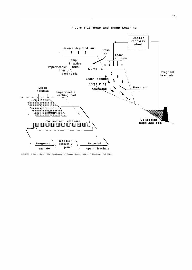
In solution mining, or leaching, water or anaqueous chemical solution percolates throughthe ore and dissolves the minerals. The resultingmineral-laden solution, known as pregnant leach-ate, is collected and treated to recover the valu-able minerals. Table 6-6 summarizes the fourtypes of solution mining.
Vat, heap, and dump leaching are methods ofhydrometallurgical processing of mined ore (seefigure 6-13). Thus they are complements, notalternatives, to underground or open pit mining.In situ leaching is a stand-alone mining method(see figure 6-14). The leach solution percolatesthrough the ore to be collected in wells or un-derground mine workings. Natural fractures orthe effects of earlier mining can supply channelsfor the leach solution, or the ore can be blastedor fractured hydraulically.27 U.S. companies have
Zzjon K. Ah Iness and Michael G. Pojar, In Situ Copper Leachingin the United States: Case Histories of Operations (Washington DC:U.S. Department of the Interior, Bureau of Mines, Circular No. 8961,1983).

119
Figure 6-10.-Underground Mining Terms
I 1 ,/
/\
l“
Chutes
SOURCE William C Peters, Exploration and Mlning Geology (New York, NY: John Wiley & Sons, 1978)
mined copper in situ at 24 known sites (see ta-ble 6-7 and box 6-A).
Solution mining enjoys certain intrinsic advan-tages over conventional mining and milling, in-cluding lower combined capital and operatingcosts, faster start-up times, and fewer adverseenvironmental impacts. Furthermore, solutionmining is an expedient method of extracting me-tals from small, shallow deposits and is particu-larly suited to low-grade resources. Leaching oldmines (where the ore that can be mined eco-nomically has been removed) and leaching wastedumps both use an in-place resource for whichthe mining cost is already “off the books. ”28 Asa result of these advantages, solution mining hasgradually taken over an increasing percentage ofdomestic mine production (see ch. 4).
There have been no truly radical technologi-cal advances in mining technology for at leastthe last several decades. Witness a 1983 U.S. Bu-reau of Mines report on Technological Innova-tIon in the Copper industry that had to stretch
z~l bid.
its time frame to the last 30 to 50 years to developa list of innovations.29 Instead, incremental im-provements in existing methods, and adaptationsof other types of technology to mining (e.g., com-puters, conveyor systems) have gradually reducedcosts and increased productivity. These includeimproved drilling and blasting equipment andpractices; larger and more efficient trucks andshovels; more efficient underground equipmentsuch as hoists and ventilation fans; computerizedtruck dispatching for open pit mines; computer-ized and remote control systems for undergroundmine pumps and trains; in-pit ore crushing andconveying; and improved slope stability analy-ses that allow steeper pit walls.
Possible future technological advances thatcould provide important productivity gains i ncopper mining include further demonstrationand development of in-pit crushing/conveying;an underground continuous mining machineadaptable to various ore and mine types; andin situ solution mining of virgin ore bodies.— —
Z9M I n~ ra I syst~rns Inc., 5U pra note 26

Figure 6-11.-Two Underground
Rook bol ts
7—
Wet fill
Drain
.- - -
● lso
-. . .
Fill
Cut-and-fill
------
Mining Methods
. . . . . . . . . . . . . . . . . . . . . . .,
stoping
. . . .. . . . . . . .. . . . ;::.:::: . . .. . .
Haulago level
Block caving
SOURCE: Willlam C Peters, Exploration and Mining Geology (New York, NY John Wiley & Sons, 1978)

121
Figure 6-12.-Open Pit Mining Terms
O v e r b u r d e n
Ore
SOURCE William C Peters. Exploration and Mining Geology (New York, NY: John Wiley & Sons, 1978)
/ w
Portion of an open-pit mine, showing benches. Holes for the explosives are drilled (right). After the ore is blasted loose,large shovels load the ore into trucks (center) for hauling to the primary crusher.

Table 6-6.—Characteristics of Solution Mining Techniques
Vat leaching Heap leaching Dump leaching In situ leachingOre grade. . . . . . . . . . . . . . . . . Moderate to high Moderate to high
Type of ore . . . . . . . . . . . . . . .Oxides, silicates, some Oxides, silicates, somesu l f ides sulf ides
Ore preparation. . . . . . . . . . . . May be crushed to optimize May be crushed to optimize
Container or pad . . . . .
Solution
Length o<
. . . . . . . . . . . .
leach cycle .
Solution applicationmethod . . . . . . . . . . . .
Metal recovery method
copper recovery copper recovery
. . . . . Large impervious vat Specially built imperviousdrainage pad
. . . . . Sulfuric acid for oxides; acid Sulfuric acid for oxides; acidcure and acid-ferric cure cure and acid-ferric cureprovide oxidant needed for provide oxidant needed formixed oxide/sulfide ores mixed oxide/sulfide ores
. . . . . Days to months Days to months
. . . . . Spraying Spraying or sprinkling
. . . . . Solvent extraction for Solvent extraction foroxides; iron precipitation oxides; iron precipitationfor mixed ores for mixed ores
LO W
Sulfides
None: waste rock used
None for existing dumps;new dumps intended to beleached would be graded,and covered with animpermeable polyethylenemembrane protected by alayer of select fill
Acid ferric-sulfate solutionswith good air circulationand bacterial activity forsulfides
Months to years
Ponding/flooding, spraying,sprinkling, trickle systems
Solvent extraction foroxides; iron precipitationfor mixed ores
Low
oxides, silicates, somesulfides
None, block caving, blasting
None
Sulfuric acid, acid cure,acid-ferric cure, or acidferric-sulfate, dependingon ore type
Months
Injection holes, spraying,sprinkling, trickle systems
Solvent extraction foroxides; iron precipitationfor mixed ores
SOURCE Office of Technology Assessment,1988; based on J. Brent Hiskey, “The Renaissance of Copper Solution Mining, ” Arizona Bureau of Geology, Fieldnotes, fall 1986,
123.
Figure 6-13.-Heap and Dump Leaching
O x y g e n depleted airFresh.
air
Temp.i n active
lmpermeable” areaIiner or”. Dump ‘L_____
Leachsolution Impermeable
. . . . . . . . . . . . . .
Leachsolution
b e d r o c k ,
Leach solution\ \
\
percolating
\downward ~
leaching pad. . . . .I I I ,
. . . . . . . . . . . . . . . . . . . . . . . . . . . .,
C o l l e c t i o n c h a n n e l ‘, \
\
.--_ -. —._. ._-. -._. ._. ___- —-. _-_. ... __. —_______\
\
\C o p p e r ‘ ,
P r e g n a n t recover y \Recycled \
Ieachate \ plan t \ spent Ieachate
\
\,\ \\
Fresh air
PregnantIeac hate
‘ \
SOURCE J Brent Hiskey, “The Renaissance of Copper Solution Mining, ” Fieldnotes Fall 1986

124
InjectionwelIs
1so
Copper
Figure 6-14.-Types of In Situ Leaching Systems
Copper
ution
\\
1flow
\
Copperrecovery
I ISolution flow
SOURCE: J. Brent Hiskey, “The Renaissance of Copper Solution Mining, ” Fieldnotes,
Copperrecovery
plant
Oxygen
Injectionwe I I
idencezone
)
,
—
I
well
/Ore

Table 6-7.—Summary of in Situ Copper Mining Activities
Cu produced Average ore Principal Cu Ore Solution/ Solution Cu in Cu recovery ActiveMine (lb/day) grade (%) minerals preparation application recovery solution (gpl) method dates
2.0, then O 8
2.02
NA
0.5-0.75
1.0
0.6
0.59, then 0.65
1.8, then 0.7
0.15b
0.2-0.6
0.835
0.5-0.6
9.23
NA
NA
Precipitation onscrap iron
Precipitation onscrap Iron
Precipitation onscrap iron
Precipitation onscrap iron
Precipitation onscrap iron
Precipitation onscrap iron
1973-74. 1978-79Big Mike (NV)
Bingham (UT)
Burro Mt. (NM)
Butte (MT)
Consolidated (NV)
Copper Queen (AZ)
5,000a
20,000b
NA
33,000b
NA
5,800 a
1.18
0.3
NA
0.8
0.3
0.29
Cuprite, tenorite,chalcopyrite
Chalcocite
Blasted pit walls,terraced
None, leachedblock-caved area
None, leachedblock-caved area
None, leachedbackfilled slopes
None, leachedblock-caved area
None, leached pitand undergroundworkings
Blasted pit bottom
Dilute H2SO4:sprinklers
Water, launder
Recovery well
Tunnel
Undergroundworkings
Tunnel
Undergroundworkings
Undergroundworkings
Recovery wells
Undergroundworkings
Recovery well
Drifts
Drifts
Driff
Drifts
Undergroundworkings
Recovery well
1922-? (now partof open pit)
1941-49Chalcocite Water
Chalcopyrite,chalcocite
Sulfides
Very dilute H2SO4:rejection
Water
1930s-1964
1925-?
Water; sprinklers 1975-presentChalcocite
250 then 750b
5,200 b
NA
NA
30,000-35,000 b
Emerald Isle (AZ)
Inspiration (AZ)
Kimbley (NV)
Medler (AZ)
Miami (AZ)
1.0
0.5
0.32
0.38
0.88C
Chrysocolla Dilute H2S04,perforated pipe
Dilute H2SO4;injection holes
Dilute H2SO4;injection
Water; floodeddrifts
Dilute H2SO4; pipespray andinjection holes
Dilute H2SO4;injection wells
Water, sprinklers
Precipitation onscrap iron
Precipitation onscrap iron
NA
3/74-6/74, then12/74-6/75
1967-74Azurite, malachite,chrysocolla
Chalcocite
None, leachedblock-caved area
None 1970-71
Sulfides None Precipitation onscrap iron
Precipitation onscrap iron, thenSX-EW
Precipitation onscrap iron
Precipitation onscrap iron
SX-EW
1906-09
Chalcocite Glory hole overblock-caved area
1942-present
4,800b
20,000b
NA
NA
5,000 a
Mountain City (NV)
Ray (AZ)
San Manuel (AZ)
Van Dyke (AZ)
Zonia (AZ)
0.93-1.1
1.0
0.47-0.72
0.5
0.2
Chalcocite
Chalcocite
Chrysocolla, cuprite
Chrysocolla
Chrysocolla
Block caving 1974
None, leachedblock-caved area
None, leachedblock-caved area
Wells drilled andhydrofraced
Blasted pit walls
1941-49
Dilute H2SO4 1986-present
Dilute H2SO4,rejection well
Dilute H2SO4,
SX-EW 1976-80
Recovery well in pit 2.0, then 0.8bottom
Precipitation onscrap iron
1973-75and bottom sprinklers
NA = not available.aMaximum.bDesign capacity.cOriginal ore body; caved stopes unknown.
SOURCE: Jon K. Ahlness and Michael G. Pojar, In Situ Copper Leaching in the United States: Case Histories of Operations (Washington, DC: U.S. Department of the Interior, Bureau of Mines Circular IC 8981).

126
Box 6-A.—The Lakeshore Mine In Situ Project
The Lakeshore Mine, near Casa Grande, Arizona, originally was a combination underground/leachingoperation. Beginning in the mid-1970s, Hecla Mining Co. developed an underground operation in whichsulfide ore was mined, crushed, and concentrated; copper sulfates were vat leached and electrowon; andoxide ores were vat leached and precipitated. Underground mining was very expensive because the sur-rounding rock was weak and the tunnels needed extraordinary support. Therefore, the mine shut downafter around two years of operation.
Noranda purchased the property in 1979. Because of the problems with the ground, they focusedon the larger oxide ore body, using block caving techniques. As the price of copper dropped, however,development of the deeper portions of the ore body became prohibitively expensive, and they began leach-ing the block caved areas, Noranda drilled injection holes through the caved areas, ran the solution intoblocked off underground haulage drifts, and then pumped it to the surface.
As the remaining ore in these areas became depleted, Noranda developed a plan for in situ leachingof the deeper, virgin ore bodies. This plan involved injecting leach solution into the “solid” ore under.pressure, with the assumption that the solution would rise to the zone of least pressure–the dammeddrifts-through the recovery wells. With an oxide ore body averaging 1..5 to 3 percent copper, this scheme,if it worked, would provide 30 years of leach production. ’ The U.S. Bureau of Mines awarded a contractfor study of in situ techniques at Lakeshore (as well as at a less developed property nearby) in 1986.
Cyprus Minerals purchased the property in mid-1987, changing the name to Cyprus Casa Grande.Cyprus hopes technologies for in situ leaching will enable it to exploit 50 million tons of oxide ore contain-ing slightly less than 1 percent copper, or around 10 million lb/yr copper leach production from therubblized ore.2
1 PauI Musgrove, GeneraI Manager, Noranda Lakeshore Mine, personal communication to OTA, April 1986,
“’Cyprus Expands Operations via Lakeshore Acquisition, ” Engineering & Mining Journal, September 1987, at p. 19,
Photo credit: Manley-Prim Photography, Tucson, AZ
Crushing the ore in the pit and using conveyor belts to haul the crushed ore to the mill greatly reduces haulage costs.

127
COMMINUTION AND SEPARATION30
The first step in separating copper from otherminerals in ore mined by underground or openpit methods is comminution (pulverization) of theore chunks—essentially from boulders to grainsof sand. (Mining is actually the first stage of sizereduction, accomplished with explosives. ) Pri-mary, secondary, and tertiary crushing reduce theore to about 25 mm, and grinding accomplishesfiner reductions. Separators (e.g., screens,cyclones 31) are used between stages to controlthe size of particles going on to the next stage.Together, comminution / separation and flota-tion/dewatering (beneficiation; see below), areknown as milling.
In terms of time, energy, and materials usedper tonne of copper produced, comminution isexpensive because the ore is still very low ingrade. Crushing and grinding consume around33 to 40 percent of the total energy required toproduce refined copper (see ch. 7).32 There alsoare significant materials costs and downtime formaintenance. Dust control in mill buildings isanother cost factor. Therefore, improvements inthe energy, materials, or operating efficiency ofcrushing could make a significant difference inproduction costs. For example, autogenous33
grinding, if technically feasible, could save around10 to 20 cents per ton of ore milled.34
Crushing often is accomplished in jaw, gyra-tory, and cone crushers, which fracture rocks bycompression (see figure 6-1 5). Jaw or gyratorycrushers are usually used for the first stage (pri-mary crushing), and cone crushers for second-ary and tertiary crushing. The choice is deter-mined by feed size (jaw crushers handle larger
Figure 6-15.—Jaw Crusher
SOURCE: Gordon L Zucker and Hassan E El-Shall, A Guide to Mineral Pro-cessing, Montana College of Mineral Science and Technology,Special Publication 85, 1982
pieces) and capacity (gyratory crushers handle3 to 4 times more rocks of a given feed size). Apneumatic or hydraulic impact breaker (similarto a jackhammer) is used to break up rocks toolarge for the primary crusher.
The crushed ore is transported, usually on con-veyer belts, to the grinding mills. Grinding millscan be operated wet or dry. I n general, whensubsequent processing is to be carried out wet(e.g., flotation), wet grinding is the logical choice.Wet grinding requires less power per tonne ofore, less space, and does not need dust controlequipment. However, it uses more steel grind-ing media and mill lining material due to corro-sion, and may be Iimited by the availability ofwater. If wet grinding is used, the crushed oreis mixed with water to form a slurry of around40 percent solids.
Grinding mills work by tumbling the ore withsteel rods or balls, or particles of the ore itself (au-togenous and semi-autogenous grinding). Be-cause the grinding media eventually wear down,new media must be added reguIarly. MiII liners,which cushion the mill shell, also wear away andmust be replaced periodically. For liner replace-ment, the individual mill has to be taken out of

128
Photo credit: Jenifer Robison
Ore is tumbled in large cylindrical mills with steel balls or rods, or chunks of hard ore (autogenous grinding),until it is pulverized.
production. Even so, mills usually can achieve99 percent operating time.
Size separators control both the size of mate-rial fed to crushers or grinders and the size of thefinal product. Thus they control both under- andovergrinding. 35 There are two types of separators:
j~There is an Optimum mix between crushing and grinding. Any
breakage produces a range of product sizes, and when the reduc-
tion ratio (feed size/product size, or amount of reduction achieved)is comparatively low, some of the feed is already as fine as the prod-
uct of that or the next phase (e.g., f ines that sift out of a primary
crusher). By screening this material out and bypassing the next re-
duct ion s tage, the s ize o f the machine can be reduced because
throughput is lower. Also, removal of finer particles will make the
equipment more efficient by reducing cushioning effects inside the
mill. Overgrinding also can be avoided by operating the final stagesin closed circuit with high circulating loads, so that material is sizedfrequently and thus has little chance of being ground unnecessarilybefore it is removed from the circuit.
screens for coarse materials, and classifiers forfines. Screens separate ore sizes mechanicallyusing a slotted or mesh surface that acts as a“go/no go” gauge. Classifiers are based on par-ticles’ settling rate in a fluid (usually water). Thehydrocyclone (figure 6-16) is the industry stand-ard for classifying because of its mechanical sim-plicity, low capital cost, and small space require-ments. Often the hydrocyclone gives relativelyinefficient separations, however, resulting in recy-cling of some concentrates for regrinding and fi-nal concentration.
Recent technological advances in comminu-tion have increased the size and efficiency ofboth crushing and grinding equipment. instru-mentation and controls have improved through-put rates and the consistency of particle size in

129
Figure 6-16.—Hydrocyclone
Vortex finder
Cylindrical section
Cyclone diameter
Replaceable liningsJ
Conical section
3
-:
‘Spiral within a spiral’
iif
Air core
Included angle ~
Apex (spigot)
Underflow
SOURCE: Errol G. Kelly and David J. Spottiswood, Introduction to Mlneral Pro-cessing (New York, NY: John Wiley & Sons, 1982).
crushing and grinding mills.36 Size separation, incontrast, has seen few significant innovationssince the basic screen was invented.
Research has improved the capacity, energyutilization, and availability of cone crushers,
JbBisWas and Davenpor t , Supra note 34.
which make finer feed for balI miIIs. This has re-duced the amount of grinding media consumed,and in some cases eliminated the need to useboth rod and ball mills.37 Autogenous and semi-autogenous grinding can eliminate the need forsecondary and tertiary crushing, allow larger milldiameters, and reduce the amount of grindingmedia consumed. Autogenous mills already havelower maintenance and capital costs than con-ventional mills. However, they only operate effi-ciently within narrow ranges of ore grade andhardness of feed material. Before autogenousgrinding can be used more widely, additionalwork is needed to develop an improved under-standing of ore properties such as hardness, mois-ture content, and shattering characteristics; andto develop more durable mechanical/electricalcomponents .38
Areas that could especially benefit from R&Dinclude: 1) better classification in closed circuitgrinding, to avoid over- and undergrinding; 2) theuse of pebble milling instead of autogenous orsteel grinding media; 3) evaluation of optimalenergy consumption in size reduction by trade-offs among blasting, crushing, grinding, and re-grinding; 4) evaluation of alternative grinding de-vices (such as attrition mills and the Schenertroller) that might have higher grinding efficien-cies; and 5) stabilizing control strategies in grind-ing and classification .39 Solution mining (dis-cussed previously) bypasses grinding, and oftencrushing,therefore
entirely; improvements in this areawould eliminate these costs.
37(_A. R o w l a n d , “Innovations in Crushing and Grinding Tech-nology, ” paper presented at the 1986 American Mining CongressInternational Mining Show, Las Vegas, NV, Oct. 5-9, 1986.
JBMineral Systems Inc., supra note 26.391 bid.

130
BENEFICIATION
The second step in separating copper fromother minerals in mined ore is beneficiation, orconcentration. The purpose of concentration isto eliminate as much of the valueless material aspossible to avoid further expense in materialshandling, transportation, and smelting. Froth flo-tation is the prevalent concentration method inthe copper industry; it separates the pulverizedore (containing around 0.6 to 2.0 percent cop-per) into concentrates (with 20 to 30 percent cop-per) plus tailings (wastes of 0.05 to 0.1 percentcopper) .40
A flotation cell resembles a large washing ma-chine (see figure 6-1 7) that keeps all particles insuspension through agitation. The ore is first con-dit ioned with chemicals that make the copperminerals water repellent (hydrophobic) withoutaffecting the other minerals. 41 Then air is bub-bled up through the pulp; with agitation, thehydrophobic copper minerals collide with andattach to the air bubbles and float to the top ofthe cell. As they reach the surface, the bubblesform a froth that overflows into a trough for col-lection. The other minerals sink to the bottomof the cell for removal .42
The simplest froth flotation operation is the sep-aration of suIfide minerals from waste oxideminerals (e. g., limestone, quartz). The separationof different suIfide minerals (e. g., chalcopyritefrom pyrite) is more complex, because the sur-faces of the minerals have to be modified so thatthe reagent attaches specifically to the mineralto be floated .43
in practice, each ore is unique. Therefore thereare no standard concentration procedures. Athorough knowledge of the mineralogy of the oreis essential for the design of a plant. Once a mill
~~Biswas and Davenport, supra note 34.~1 The principal chemical reagent used is the colIector, which at
taches (adsorbs) preferentially to the mineral to be recovered. ToImprove the degree of selective adsorption, other chemicals maybe added to the slurry, Including activators, which modify the sur-face properties of a mineral so that it becomes more amenable toflotation; depressants, which reduce the floatability of one or moremineral constituents; dispersion agents to help the selective reactionof other reagents; and pH regulators.
JIBlswas and Davenport, supra note 34.
d ~lbid.
Figure 6-17.— Flotation Cells
Upper portionof rotordraws air downthe standpipefor thoroughmixing with pulp
of
ulp
Larger flotation /units include falsebottom to aid pulp flow
SOURCE: Errol G. Kelly and David J Spottiswood, Introduction to Mineral Pro-cessing (New York, NY: John Wiley & Sons, 1982),
is in operation, continued appraisal of the miner-alogy is critical to fine tuning to maintain effi-ciency. This arises because ore bodies are nothomogeneous; variations in feed mineralogy arenormal and may occur to such an extent that ma-jor circuit modifications are required.44
Conventional flotation is carried out in stages,the purpose of each depending on the types of
~Kelly and Spottiswood, supra note 30.

131
Photo credit: US. Bureau of Mines
I n f I o t a t i o n , t h e c o p p e r a t t a c h e s t o b u b b l e s a n d f l o a t s
to the top, where it forms a froth that overflows intoa trough for collection,
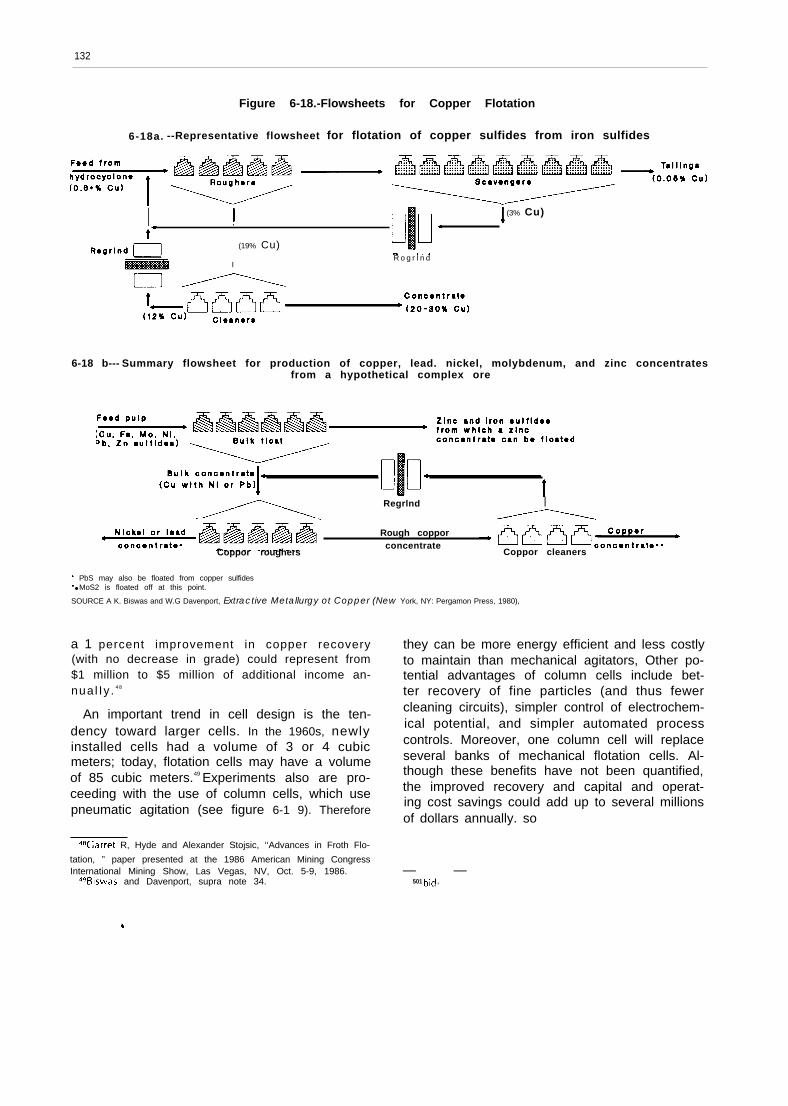
minerals in the ore (see figure 6-18). Selective flo-tation for copper sulfide-iron sulfide ores usesthree groups of flotation cells (figure 6-1 8a):
●
●
●
roughers use a moderate separating force tofloat the incoming ore to produce a highcopper recovery with a concentrate gradeof 15 to 20 percent;cleaners use a low separating force to up-grade the rougher concentrate by removingmisplaced waste material, resulting in a fi-nal high-grade copper concentrate of 20 to30 percent and;scavengers provide a final strong flotationtreatment for the rougher tailings (with alarge concentration of reagent and vigorousflotation) to recover as much copper aspossible.
As shown in figure 6-1 8a, the tailings from thecleaner flotation and the “float” from the scav-
enger flotation (middlings) are returned to thestart of the circuit. A regrind often is necessaryfor this to be effective. Alternatively, there maybe a regrind between rougher and cleaner flota-t ion,45
For more complex ores, the first stage often isa bulk float, similar to the rougher, i n which muchof the waste and some of the byproduct metalsare eliminated (figure 6- 18b). The buIk concen-trate then goes to roughers, which float the cop-per and eliminate the remaining metals, and thento cleaners. Again, there may be a regrind andsecond rougher cycle.46
The product of froth flotation contains 60 to80 percent water, most of which must be re-moved before the concentrate can be transportedor smelted, Dewatering is accomplished first bysettling in large vats, known as thickeners. Thesolids settle by gravity to the bottom of the vat,where they are scraped to a discharge outlet bya slowly rotating rake.47 Filters are used for finaldewatering.
Over the last 10 to 20 years, advances havebeen made in flotation chemicals, flotation celldesign, and automated circuits. Automated flo-tation monitoring and control systems improvemetal recovery and reduce reagent consumption.Most U.S. operations have now installed thesesystems. Continued improvements in sensitivitywouId enhance the potential savings, however.
In flotation chemistry, a major developmentwas the recognition that adsorption of sulfideminerals on air bubbles is an electrochemicalprocess. Changing the electrochemical potential(by varying the chemical reagents) activates ordepresses the various minerals, making them floator not float, and thus improves flotation effi-ciency. This offers significant savings—perhaps $1million annually—in reagent costs. Other poten-tial benefits of electrochemical control includehigher recoveries and lower operating costs, Even
qsBiSWas and Davenport, supra note 34.
’61 bid.~zThe liquid from the thickeners usualIy is recycled to the grind-
ding and flotation circuits. This prevents adverse environmental im-pacts from the trace metals in the liquid (e.g., copper, arsenic, cad-mium, lead, and zinc; see ch. 8). Water recycle systems also reducewater use, an important consideration i n the arid regions wheremuch of the world’s copper is produced.
132
Figure 6-18.-Flowsheets for Copper Flotation
6-18a. --Representative flowsheet for flotation of copper sulfides from iron sulfides
I I (3% Cu)
I
(19% Cu)R o g r I n d
6-18 b--- Summary flowsheet for production of copper, lead. nickel, molybdenum, and zinc concentratesfrom a hypothetical complex ore
Regrlnd I
Rough copporconcentrate
Coppor roughers Coppor cleaners
“ PbS may also be floated from copper sulfides9 ● MoS2 is floated off at this point.
SOURCE A K. Biswas and W.G Davenport, Extractive Metallurgy ot Copper (New York, NY: Pergamon Press, 1980),
a 1 percent improvement in copper recovery(with no decrease in grade) could represent from$1 million to $5 million of additional income an-nual Iy . 48
An important trend in cell design is the ten-dency toward larger cells. In the 1960s, newlyinstalled cells had a volume of 3 or 4 cubicmeters; today, flotation cells may have a volumeof 85 cubic meters.49 Experiments also are pro-ceeding with the use of column cells, which usepneumatic agitation (see figure 6-1 9). Therefore
they can be more energy efficient and less costlyto maintain than mechanical agitators, Other po-tential advantages of column cells include bet-ter recovery of fine particles (and thus fewercleaning circuits), simpler control of electrochem-ical potential, and simpler automated processcontrols. Moreover, one column cell will replaceseveral banks of mechanical flotation cells. Al-though these benefits have not been quantified,the improved recovery and capital and operat-ing cost savings couId add up to several millionsof dollars annually. so
~aGarret R, Hyde and Alexander Stojsic, ‘‘Advances in Froth Flo-
tation, ” paper presented at the 1986 American Mining CongressInternational Mining Show, Las Vegas, NV, Oct. 5-9, 1986.
~gBiswas and Davenport, supra note 34.— —
501 bid ,

133
F i g u r e 6 - 1 9 . - C o l u m n C e l l Column cells already are used for molybdenum
‘,
Wash water
D i a m e t e r -
(throughput )
I I
I
I
Cleaningzone
( g r a d e )
C o l I e c t i o nzone
Tai I ings
concentration, and are being tested in coppermilling. Experience with a column cell at SanManuel, Arizona showed a concentrate grade of29.83 percent copper with a sulfide copper re-covery of 90.36 percent, compared to the con-ventional San Manuel flotation circuit with 29.99percent copper in the concentrate and a recov-ery of 90.12 percent .51
51 13. V. Clingan and D. R. McGregor, ‘‘Column Flotation Experi-
SOURCE J D McKay et al “Column Flotation, ” U.S. Bureau of Mines pamphlet, e n c e a t M a g m a C o p p e r C o m p a n y , ” M i n e r a l s a n d M e t a l l u r g i c a l
undated Processing, vol. 4, No. 3, August 1987, p. 121.
PYROMETALLURGY
Pyrometa l lu rg ica l processes employ h igh- of equipment, pyrometallurgical recovery maytemperature chemical reactions to extract cop- take as many as four steps: roasting, smelting,per from its ores and concentrates.52 These proc- converting, and fire refining.esses generally are used with copper sulfides and,in some cases, high-grade oxides. The use of high Smelting is a relatively small component in thetemperatures for metallurgical processing has sev- total cost of copper production—about 17 per-eral advantages: chemical reaction rates are cent of gross U.S. production costs. In relativerapid, some reactions that are impossible at low terms, however, the United States is least com-temperature become spontaneous at higher tem- petitive in smelting.. This is primarily attributa-perature, and heating the mineral to a liquid fa- ble to high U.S. labor and energy costs. Thus, im-cilitates separation of the metal from the residue. provements in smelter labor productivity andDepending on the copper minerals and the type energy efficiency would enhance domestic indus-
5 2 Pyrometa l lu rg ica l p rocesses typ tca l ly opera te a t temperatures try competitiveness, Domestic smelters also arerang ing f rom 500° C to 1250° C. at a disadvantage compared to some other coun-

134
tries due to the high level of environmental con-trol required in the United States (ch. 10).
Roasting prepares ores and concentrates foreither pyrometallurgical or hydrometallurgicalprocessing. For the former, it dries, heats, andpartially removes the sulfur and volatile contami-nants (e. g., arsenic) from the concentrate to pro-duce a calcine suitable for smelting. In hydro-metallurgical processing, roasting converts sulfideminerals to more easily leachable oxides and sul-fates .53
5 3 B i s w a s a n d D a v e n p o r t , s u p r a n o t e 3 4 .
In smelting, concentrates or calcines are proc-essed at high temperatures to produce a liquidcopper-rich matte for converting, plus slag andsulfur dioxide (S02). The heat required to meltthe concentrate is generated from three sources:1) retained heat from roasting, 2) external energysources such as fossil fuels and electricity, and3) the heat produced by the chemical combina-tion of iron sulfides with oxygen, The slag is dis-carded, either directly or after further copper re-covery in an electric furnace or flotation cell. TheSO2 is captured for pollution control (see ch. 8).
Figure 6-20 shows changes in smelting technol-ogy along with the increase in copper produc-

135
Figure 6-20.-Development of Smelting TechnologyCompared with World Copper Production
I Smelting
I Roas t -1 Blast furnace reduction ?
Rever beratory furnace Last now u n i t
x ‘ - - - - - - - - -
ox y -fueIburner
Sprinkle smelting - . . . . . .
1EIectric furnace. . .
Outokumpu processUse of 0 2
INCO process
0 2N o r a n d a p r o c e s s .
Mitaubiahi process
Top-blown rotary . . . . .
converter process
Piere-Smith convertor
Hoboken convortor
EI Tenlento converter
Mitaubiahi continuous convertor
I Million tonnes10
*
1 ~ /Production
, ,0.1+ , , , ,1900 1920 1940 1960 1980 2000
SOURCE United Nat Ions Industrial Development Organization
tion. The earliest large-scale method of produc-ing copper matte was in blast furnaces, whichcould handle ores containing 5 to 20 percent cop-per. With the decline in ore grades, direct smelt-
ing became too expensive, and the industryshifted to concentration fol lowed by hearth orreverberatory smelting (see box 6-B). Flash fur-naces, which combine roasting and hearth smelt-ing and are more efficient than reverberatories,were introduced in the 1940s.
In recent years, concerns about the air qualityimpacts of reverberatory furnaces have led to thewidespread adoption of electric and flash fur-naces in the United States. As table 6-8 shows,almost all of the domestic smelters that are stilloperating upgraded their furnaces from reverber-atories to more modern technology within thelast 15 years. Most furnaces that were not up-graded were closed permanently (e.g., PhelpsDodge’s Douglas, Morenci, and Ajo smelters;Kennecott’s Ely and Ray smelters; Anaconda’sButte smelter; Asarco’s Tacoma plant) .54
Copper matte converting is the final stage insmelting; it usually is carried out in a Pierce-Smithconverter (figure 6-25), which separates the matteinto blister55 copper (at least 98.5 percent cop-per) and slag. After the molten matte is pouredinto the converter, air is blown into the mattethrough nozzles (called “tuyeres”). First, the ironsuIfide in the matte oxidizes into iron oxide andSO2; silica is added and the iron oxide forms aniron silicate slag, which is poured off after eachblow. This leaves molten copper sulfide (whitemetal or chalcocite, CU2S). The remaining suIfu rin the white metal is then oxidized to SO2, leav-ing blister copper. Converter slags contain from2 to 15 percent copper, and generally are recy-cled to the smelting furnaces, where their highiron content often serves as a smelting flux.56
Continuous production of blister copper haslong been a goal of copper producers. Contin-uous reactors combine roasting, smelting, andconverting in one operation that produces blis-ter copper directly from concentrates, while tak-ing advantage of the heat generated by the oxi-
dation of sulfides. The benefits of continuous
— . . —~~The decline in domestic smelter capacity is discussed in ch. four.
‘ 5 T h e t e r m “ b l i s t e r ” r e f e r s t o t h e b u m p s o n t h e s u r f a c e o f t h e
copper created when the oxygen and sulfur that remain dissolvedat high temperatures form gases when the copper is solidified.
~bA flux IS a substance that facilitates the separation of the smeltercharge into matte and slag.
136
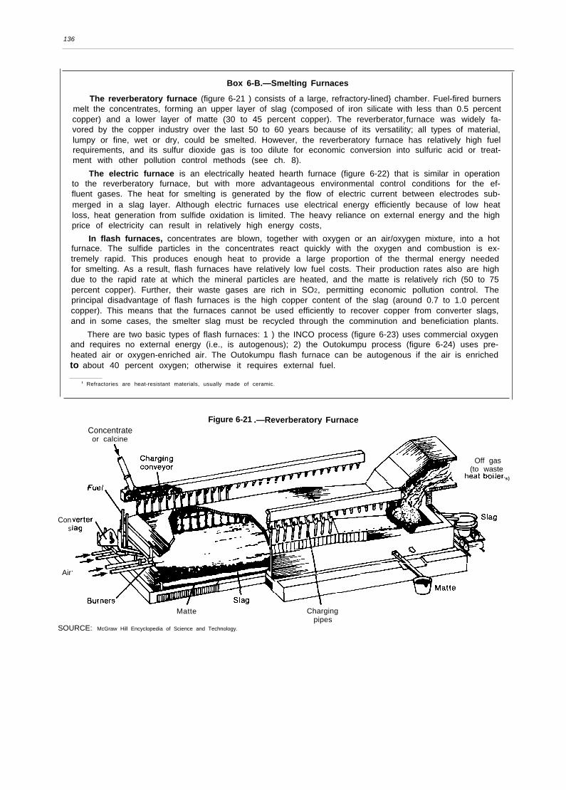
Box 6-B.—Smelting Furnaces
The reverberatory furnace (figure 6-21 ) consists of a large, refractory-lined} chamber. Fuel-fired burnersmelt the concentrates, forming an upper layer of slag (composed of iron silicate with less than 0.5 percentcopper) and a lower layer of matte (30 to 45 percent copper). The reverberatory furnace was widely fa-vored by the copper industry over the last 50 to 60 years because of its versatility; all types of material,lumpy or fine, wet or dry, could be smelted. However, the reverberatory furnace has relatively high fuelrequirements, and its sulfur dioxide gas is too dilute for economic conversion into sulfuric acid or treat-ment with other pollution control methods (see ch. 8).
The electric furnace is an electrically heated hearth furnace (figure 6-22) that is similar in operationto the reverberatory furnace, but with more advantageous environmental control conditions for the ef-fluent gases. The heat for smelting is generated by the flow of electric current between electrodes sub-merged in a slag layer. Although electric furnaces use electrical energy efficiently because of low heatloss, heat generation from sulfide oxidation is limited. The heavy reliance on external energy and the highprice of electricity can result in relatively high energy costs,
In flash furnaces, concentrates are blown, together with oxygen or an air/oxygen mixture, into a hotfurnace. The sulfide particles in the concentrates react quickly with the oxygen and combustion is ex-tremely rapid. This produces enough heat to provide a large proportion of the thermal energy neededfor smelting. As a result, flash furnaces have relatively low fuel costs. Their production rates also are highdue to the rapid rate at which the mineral particles are heated, and the matte is relatively rich (50 to 75percent copper). Further, their waste gases are rich in SO2, permitting economic pollution control. Theprincipal disadvantage of flash furnaces is the high copper content of the slag (around 0.7 to 1.0 percentcopper). This means that the furnaces cannot be used efficiently to recover copper from converter slags,and in some cases, the smelter slag must be recycled through the comminution and beneficiation plants.
There are two basic types of flash furnaces: 1 ) the INCO process (figure 6-23) uses commercial oxygenand requires no external energy (i.e., is autogenous); 2) the Outokumpu process (figure 6-24) uses pre-heated air or oxygen-enriched air. The Outokumpu flash furnace can be autogenous if the air is enrichedto about 40 percent oxygen; otherwise it requires external fuel.
1 Refractories are heat-resistant materials, usually made of ceramic.
Figure 6-21 .—Reverberatory FurnaceConcentrateor calcine
Cons
Air
Off gas(to waste
‘s)
Matte Chargingpipes
SOURCE: McGraw Hill Encyclopedia of Science and Technology.

137
Figure 6-22.— Electric Furnace
Legend
1.23.4.5.6.
7.8.9.
Drain out taphole 10BuckstayTie-rod 11Tie-rod spring 12Electrode openings 13Furnace Inspect Ion 14ports 15Furnace support pi liars 16Matte tapping blocksMagnesite refractory bricks
Magnesite hearth andsub-hearthMagnesite castableFire-clay bricksFirebrick roofSlag tapholesAverage slag levelAverage matte level
SOURCE A K Blswas and W G. Davenport, Extractlve Metallurgy of Copper(New York, NY Pergamon Press, 1980)
blister copper production include lower capitalcost, reduced materials handling, low heat losses,very IOW energy requirements, economical S O2
gas recovery, and the ability to apply online com-puter controls to the entire copper-makingprocess.
Two types of continuous reactors are in limiteduse: the Noranda process and the Mitsubishiprocess. The Noranda reactor (see figure 6-26)is a single-step process that always contains threeliquid phases–slag, matte, and blister copper.The Mitsubishi reactor (figure 6-27) has three in-terconnected furnaces through which matte andslag flow continuously by gravity.
Neither of these processes has yet proven tobe truly continuous. First, the slag contains asmuch as 10 percent copper. Slag from the Nor-anda reactor is recycled through comminutionand beneficiation. Mitsubishi slag is reprocessedin the intermediate electric settling furnace. Sec-
ond, the blister copper from the Noranda reactorcontains more impurity metals (e. g., antimony,arsenic, bismuth) than blister produced by con-ventional smelting/converting. This requires ei-ther more expensive electrorefining or the restric-tion of single-step continuous smelting to ratherpure concentrates. Third, while the Noranda re-actor operates more efficiently with oxygen-enriched air, oxygen levels above about 30 per-cent greatly increase equipment wear. As a re-sult, the Noranda reactor typically is used to pro-duce a very high-grade matte (70 to 75 percentcopper), which is then treated i n a converter.
Fire refining further purifies blister copper toproduce anodes pure enough for electrorefining.The residual sulfur is removed by blowing airthrough the molten blister (in a furnace similarto a Pierce-Smith converter) to form SO2, untilthe sulfur content has been lowered to 0.001 to0.003 percent. The oxygen is then removed byblowing natural gas or propane through thetuyere until oxygen concentrations have droppedto 0.05 to 0.2 percent.
The molten copper is then poured into ananode casting wheel—a circular arrangement thatis rotated to bring the molds u rider the furnacemouth. The anodes are cooled with water spraysas the wheel rotates. The critical parameters i nanode casting are smoothness, straightness, anduniform thickness to ensure efficient electro-refining.
Recent improvements in pyrometallurgicalprocessing of copper concentrates have focusedon reducing energy requirements (see ch. 7) andon producing fewer gaseous emission streamswith higher SO2 concentrations for more cost-effective air pollution control (ch. 8). Better qual-ity control of the product to reduce materials re-handling also has been a factor. Most domesticsmelters now have on-line computer controls forgreater throughput with better matte quality andalmost automatic operation.
One area in which further improvementswould greatly assist the United States is contin-uous smelting, because it would decrease ma-terials handling and therefore increase laborproductivity, would decrease energy use, and

138
Figure 6-23.— INCO Flash FurnaceConcentrates and
10 cm
30-cm
SOURCE: A.K. Blswas and W.G. Davenport, Extractive Mefallurgy of Copper (New York, NY: Pergamon Press, 1980).
Figure 6.24.—Outokumpu Flash FurnaceConcentrate
and sand
//
SettlerSlag
Matte
SOURCE: McGraw Hill Encyclopedia of Science and Technology.
Table 6.8.-Smelter Technology inthe United States
Smelter Type
Hayden (Arizona). . . . . . . . . . . . INCO flash furnace —
Inspiration (Arizona) . . . . . . . . . Electric furnaceMorenci (Arizona)* . . . . . . . . . . Reverberatory furnaceSan Manuel (Arizona) . . . . . . . . Outokumpu flash furnaceWhite Pine (Michigan) . . . . . . . Reverberatory furnaceHidalgo (New Mexico) . . . . . . . INCO flash furnaceHurley (New Mexico) . . . . . . . . INCO flash furnaceGreat Falls (Montana)*. . . . . . . Electric furnaceCopperhill (Tennessee)* . . . . . Electric furnaceEl Paso (Texas) . . . . . . . . . . . . . Reverberatory furnaceGarfield (Utah) . . . . . . . . . . . . . . Noranda reactor‘Not operating,
—
SOURCE Office of Technology Assessment, 1988,
would make environmental control more cost-effective. However, installation of an entirely newsmelting system has a high capital cost. Becausemost U.S. smelters already installed new furnaceswithin the last 15 years, it is unlikely that they
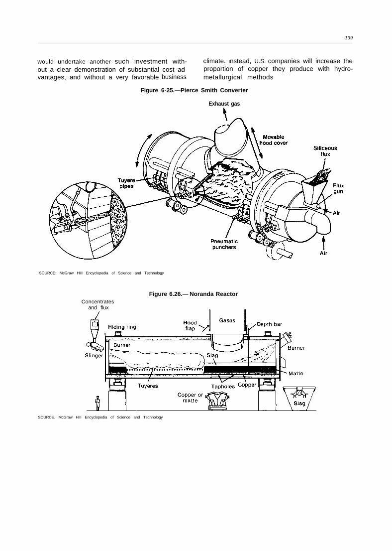
139
would undertake another such investment with- climate. Instead, U.S. companies will increase theout a clear demonstration of substantial cost ad- proportion of copper they produce with hydro-vantages, and without a very favorable
Figure
business metallurgical methods
6-25.—Pierce Smith Converter
Exhaust gas
SOURCE: McGraw HiII Encyclopedia of Science and Technology
Figure 6.26.— Noranda ReactorConcentrates
and flux
SOURCE. McGraw HiII Encyclopedia of Science and Technology

140
Figure 6-27.— Mitsubishi Continuous Smelting System
Slag granulationand discard
Concentrates,S i02, air, 02
Exit gas
GranulationSOURCE: McGraw HiII Encyclopedia of Science and Technology.
HYDROMETALLURGY
Hydrometallurgical copper recovery is the ex-traction and recovery of copper from ores usingaqueous (water-based) solutions. Hydrometallur-gical processes are applied mainly to oxide ores,and to low-grade oxide and sulfide mine wastes. STAs discussed in the section on mining, above, andin chapter 4, about 25 percent of domestic cop-per production is now through the use of solu-tion mining techniques. Once the ore has beenleached, the copper is recovered from the preg-nant Ieachate through precipitation or solvent ex-traction.
5Tchemlca solutions aIso can be used to process copper con-
centrates. While several of these solutions are commercially avail.able, their materials and energy costs are higher than for conven-tional smelting or leaching (see ch. 7).
These processes have several advantages overpyrometallurgical copper recovery methods, in-cluding the ability to treat lower grade ores (evenwaste dumps) economically, flexibility in scaleof operations, simplified materials handling,and good operational and environmental con-trol. Copper can be produced from dump leach-ing plus solvent extraction and electrowinning foraround 30 cents per pound .58 This is a clear costadvantage over pyrometallurgical production.
Solvent extraction is still largely confined tocopper oxides. Hydrometallurgical techniques for
~BEcjwarcj E. Malouf, “New Developments in Hydrometallurgy, ”
paper presented at the American Mining Congress Mining Conven-tion, San Francisco, CA, Sept. 22-25, 1985.

141
suIfides and complex ores are being developed. the solution, and the copper, which precipitatesThese will greatly aid the United States in over- out of the solution. Cement copper detaches fromcoming its low ore grade disadvantage. It should the steel surfaces as flakes or powder under thebe made clear, however, that dump leaching– force of the flowing solution. There are numer-exploitation of low-grade mine wastes—is primar- ous precipitator designs and configurations (see,ily a means of lowering average production costs. for example, the Kennecott cone precipitatorIt is not a substitute for conventional copper pro- shown in figure 6-28).duction by pyrometallurgical or other leachingmethods.
In iron precipitation, or cementation, the preg-nant leach solution flows through a pile of scrapiron/steel, and the copper precipitates onto thesteel surfaces. Precipitation works through anelectrochemical reaction: there is a transfer ofelectrons between the iron, which dissolves into
The principal advantage of precipitation is thatvirtually all of the copper is recovered from theIeachate. Cement copper is still relatively impure,however, and subsequent treatment is required,usually through normal smelting/refining. Typi-cally, cement copper contains around 85 to 90percent copper, 0.2 to 2 percent iron, plus traceamounts of silica and aluminum oxides, andoxygen.
Photo credit Manley-Prim Photography, Tucson, AZ
A solvent extraction-electrowinning plant. The pregnant Ieachate flows to the collection ponds upper left). The solventextraction tanks are shown at center, and the electrowinning plant at lower right.

142
Figure 6-28.– Kennecott Cone Precipitator
Barren solution -
Copper settling .and
collection zone -
Copper d ischarge
solutionSOURCE: A K. Blswas and W.G. Davenport, Extractive Metallurgy of Copper
(New York, NY: Pergamon Press, 1980).
In solvent extraction, an organic chemical thatdissolves copper but not impurity metals is mixedwith the pregnant Ieachate from solution mining.The copper-laden organic solution is separatedfrom the Ieachate in a settling tank. Sulfuric acid
(H2S O4) is then added to the pregnant organicmixture, which strips the copper into an electro-lytic solution for electrowinning (see below).
Solvent extraction is advantageous in that theelectrolyte has almost no impurities and few envi-ronmental problems. Solvent extraction alsomakes relatively efficient use of the various so-lutions used: the spent Ieachate is returned to theleaching operation, the barren solvent is recycledto the pregnant Ieachate, and the spent electro-lyte to the loaded solvent (see figure 6-29).59
New developments in hydrometallurgy haveresulted primarily from a better understanding ofthe chemical and biological processes that oc-cur in leaching; from improved heap and dumpconstruction methods that speed up the leach-ing process; from automated controls and im-proved solvent recycling rates in solvent extrac-tion; and from advancements in electrowinning(see below).
59Biswas and Davenport, supra note 34.
ELECTROMETALLURGY 60
Electrometallurgy deals with the use of electri-city to refine metals. Virtually all primary copperreceives electrolytic treatment, either throughelectrorefining of copper anodes or electrowin-ning of solvent extraction solutions. In essence,an electric current is used to bring about chemi-cal changes that extract (electrowin) or purify(electrorefine) the copper.
Refining is the stage of copper production inwhich the United States is most cost competi-tive. . This is due in part to low delivery costs andin part to major improvements in refinery laborproductivity. More widespread use of automatedcontrols and materials handling systems shouldenhance our refining cost position further. Be-cause refining is only around 8 percent of the totalcost of copper production, however, it provideslittle leverage in overall competitiveness.
60The material in this Section is from Biswas and Davenport, Supra
note 34, unless otherwise noted.
Electrorefining virtually eliminates the oxygen,sulfur, and base metals that are harmful to cop-per’s properties (e.g., reduce its electrical con-ductivity) and decrease its value. At the sametime, electrorefining allows the recovery of val-uable impurities such as gold and silver. The endproduct, cathode copper, is 99.99+ percentpure, with less than 0.004 percent metallic andother impurities (including sulfur).
In electrorefining, the fire-refined copperanodes are hung vertically in between cathodestarter sheets in long tanks, or cells, filled withan acidic copper sulfate solution. Usually thecathode starter sheets are themselves thin piecesof copper, which become incorporated into thecathode. An electric current is run through thesolution and the copper gradually corrodes fromthe anode and plates onto the cathode. The cath-ode copper is shipped to the rod mill or fabrica-tor for melting and casting.
Electrowinning is the recovery of copper fromthe loaded electrolyte solution produced by sol-

143
Figure 6-29.-Flowsheet for Solvent Extraction
P r e g n a n t
B a r r e n l e a c h
\ t o l e a c h
S e t t l e r
Load e dsoIvent II
II II
L o a d e deIectroIyte
SOURCE: A. K. Blswas and W.G. Davenport, Extractive Metallurgy of Copper (New York, NY: Pergamon Press, 1980).
vent extraction. The basic difference betweenelectrowinning and electrorefining is that in theformer, the copper is already in the electrolyte.Therefore, electrowinning uses inert (non-dissolv-ing) anodes, typically made of lead alloyed withcalcium and tin, or of stainless steel. These reactelectrochemically to produce oxygen gas and sul-furic acid, The cathode copper is stripped fromthe starter sheets (which are reused), and thenshipped to the rod mill or fabricator. The acid isrecycled to the leaching operation. The cells andelectrical circuitry are otherwise similar to thoseused in electrorefining, although voltages arehigher.
Recent innovations in electrorefining and elec-trowinning have focused on increased produc-
a t e
Itivity through automation and periodic currentreversal. Automation of electrometallurgy oper-ations includes computer monitoring of cell vol-tages, infrared scanning of cells to locate and cor-rect short-circuits, robotic cathode stripping,programmable robotic cranes for automatedanode and cathode handling, and machinestraightening of cathode starter sheets.61 Periodi-cally reversing the direction of the direct currentfor a brief period can increase refinery capacityby as much as 15 percent.62
61 Mineral Systems Inc., supra note 26.62 Biswas and Davenport, Supra note 34.
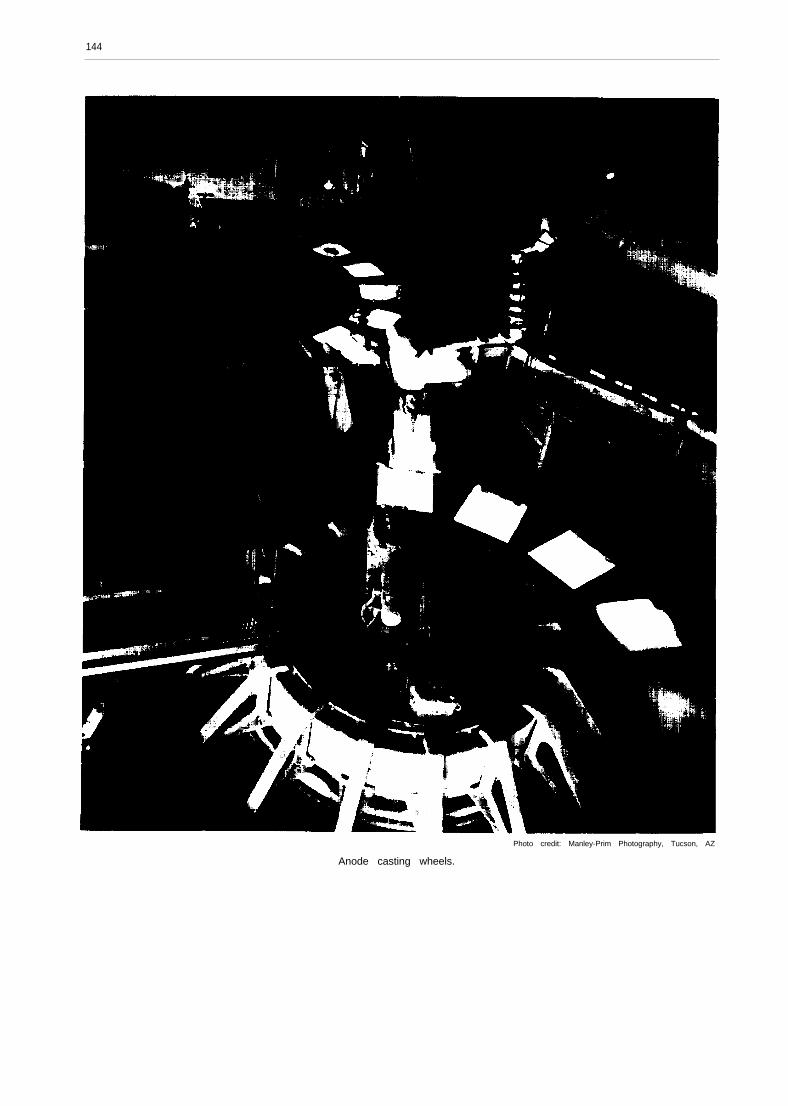
144
Photo credit: Manley-Prim Photography, Tucson, AZ
Anode casting wheels.

145
MELTING AND CASTING
Cathode copper is melted and cast into con- . oxygen-free copper, which combines thetinuous rod or wirebars for wire manufacture, high electrical conductivity of electrolyticinto slabs or biIlets for mechanical use, or ingots tough pitch copper and the weldability offor alloying. The three major forms of copper are: phosphorus deoxidized copper, for finely-
● electrolytic tough pitch copper (less than0.001 percent sulfur, 0.0015 to 0.03 percentoxygen) for wire and other electrical uses;
● phosphorus deoxidized copper (begins witha 90 percent copper and 10 percent phos-phorus alloy, removes the oxygen as P205,leaving 99.95 to 99.99 percent copper and0.01 to 0.05 percent phosphorus) for plumb-ing, radiators, and other uses requiring weld-ing; and
drawn wire and electronic components.
The cathodes typically are melted in a shaft fur-nace. They are placed in an opening near the topof the furnace and melt as they descend the shaft.The liquid copper flows immediately into a sep-arate gas-fired or induction-heated holding fur-nace, and then to casting.
Most mills making electrolytic copper now usecontinuous casting machines that integrate the
Photo credit Manley Prim Photography, Tucson, AZ
Cathode starter sheets above the electrorefining cells.

146
casting and subsequent fabrication of 5/16-inchrod in one continuous operation. I n the contin-uous casting wheel patented by Southwire Corp.,the liquid copper is poured onto a wheel witha bar-shaped well in the rim (figure 6-30). As thewheel turns, a belt covers the copper and it ispartially cooled with a water spray. It exits theother end of the wheel as a red-hot but solidi-fied continuous bar that then enters a single-passrod-rolling mill (see figure 6-31 ). In the mill, thebar is extruded in several stages until it is the re-quired thickness. When nearly cool, it is coiledautomatically.
Before shipping to customers, the rod is testedin a metallurgy lab for surface quality, electrical
conductivity, chemical composition, and physi-cal properties such as hardness, tensile strength,and elongation failure. Any batch that does notmeet standards is remelted and recycled throughthe rod mill.
Continuous cast rod–now the industry stand-ard—brought substantial improvements in pro-ductivity in melting and casting, through bothautomation and significant increases in the qualityof the final product and thus fewer batches thathave to be reprocessed.
Figure 6-30.—Continuous Casting Wheel
Cross section rim moldfor a 35 cm2 bar
SOURCE: A.K. Biswas and W.G. Davenport,
cm Casting
After cooler Pouring spout (removable)\
Extractive Metallurgy of Copper (New York, NY: Pergamon Press, 1980).
. 3 mm steel band(removable)
~ Band spray
z Copper castingwheel rim
(removable)
~ Idler wheel

147
Figure 6-31 .—Continuous Rod Rolling Mill
ASARCOshaft
Automaticloading
conveyor Gas
furnace
i red
60 m*NOTE The numbers refer to sensor positions for automatic control
SOURCE A K Biswas and W G Davenport, Extractive Metallurgy of Copper (New York, NY: Pergamon Press, 1980)