Coordination of LV protection devices - Schneider … of LV protection devices ... 2.6. Coordination...
48
Coordination of LV protection devices n° 5 Low Voltage Expert Guides
Transcript of Coordination of LV protection devices - Schneider … of LV protection devices ... 2.6. Coordination...

Coordination of LV protection devices
n° 5
Low Voltage Expert Guides
DBTP107_EN_Couv.indd 1 27/02/2008 17:40:55


version: 1.0 1
Contents
Glossary 2The requirements of electrical power distribution 3 1.1. Safety and availability of energy 31.2. Structure of LV electrical power distribution 41.3. Functions and technologies of the protection devices 5
1.3.1. Circuit-breaker functions 51.3.2. Level A: the MSB 51.3.3. Level B: the subdistribution boards 61.3.4. Level C: Final distribution 7
1.4. Standard IEC 60947-2 81.4.1 The principles 81.4.2. Reminders of standard-related electrical data 91.4.3. Circuit-breaker coordination 11
1.5. Summarising table 12
The implementation techniques 132.1. Limitation 13
2.1.1. Principles 132.1.2. Circuit breaker limitation capacity 142.1.3. Advantages 142.1.4. Limitation curves 16
2.2. Cascading 172.2.1. Area of application 17
2.3. Discrimination 192.3.1. General information 192.3.2. Technical discriminations 20
2.4. The discrimination rules 232.4.1. General discrimination rules 23
2.5. Earth leakage protection discrimination 242.5.1. Vertical discrimination 242.5.2. Horizontal discrimination 25
2.6. Coordination of protection devices installation standards 26Schneider Electric choice 283.1. For power circuit-breakers 29
3.1.1. The selective pole 293.1.2. Technical innovations of new Masterpact for better performances 29
3.2. For moulded case circuit-breakers (MCCB) 343.2.1. Trip units 34
3.3. For miniature circuit-breakers MCB 353.4. The discrimination rulesfrom 1 to 6300 A 36
3.4.1. General discrimination rules (in distribution) 363.4.2. Discrimination rules for Masterpact NT and NW 363.4.3. "Natural" discrimination rules between Compact NSX 373.4.4 Discrimination enhanced by cascading with the Compact NS 383.4.5. Specific applications 393.4.6. Summary 39
Implementation of discrimination and cascading 404.1. Discrimination tables 404.2. Cascading tables 404.3. Study of MV/LV discrimination from 1 to 6300 A 41
4.3.1. At the MSB 424.3.2. Cascading 424.3.3. At the power distribution switchboard � 434.3.4. At the subdistribution switchboard � 434.3.5. At the final distribution switchboard � 43
DBTP107_EN_Pint.indd 1 27/02/2008 16:07:20

version: 1.02
EDW: electrodynamic withstand
SCPD: short circuit protection device
IEC: International Electrotechnical Commission
CT: current transformers
CU: control unit
MSB: main switchboard
BBT: busbar trunking
MV: nedium voltage (1 kV to 36 kV)
lsc: short-circuit current
lsc(D1): short-circuit current at the point where D1 is installed
Usc: short-circuit voltage
MCCB: moulded case circuit-breaker
BC : breaking capacity
lcu(1): ultimate breaking capacity IcuD1(1): ultimate breaking capacity of D1
(1) The main electrical data of circuit-breakers are defined on page 8.
Glossary
DBTP107_EN_Pint.indd 2 27/02/2008 16:07:20

version: 1.0 3
The requirements of electrical power distribution
1.1. Safety and availability of energy
Implementation of these protection devices must allow for:the statutory aspects, particularly relating to safety of people,technical and economic requirements.
The chosen switchgear must:withstand and eliminate faults at optimised cost with respect to the necessary
performance,limit the effect of a fault to the smallest part possible of the installation in order to
ensure continuity of supply.
Achievement of these objectives requires coordination of protection device performance, necessary fof:
managing safety and increasing durability of the installation by limiting stresses,managing availability by eliminating the fault by means of the circuit-breaker
immediately upstream.
The circuit-breaker coordination means are:cascading,discrimination.
If the insulation fault is specifically dealt with by earth leakage protection devices, discrimination of the residual current devices (RCDs) must also be guaranteed.
bb
b
b
bb
bb
Safety and availability of energy are the operator’s prime requirements.Coordination of protection devices ensures these needs are met at optimised cost.
In sh
ort
The design of LV installations leads to basic protection devices being fitted for three types of faults:
overloadsshort-circuitsinsulation faults
bbb
DBTP107_EN_Pint.indd 3 27/02/2008 16:07:20

version: 1.04
1.2. Structure of LV electrical power distribution
The various levels of an LV electrical installationEach of the three levels of the installation has specific availability and safety needs.
Simplified diagram of a standard installation covering most of the cases observed in practice.
DB
1163
05
The requirements of electrical power distribution
mainswitchboard
Level A
Level B
Level C
distributionworkshop 1
power distributionswitchboard -industrial / tertiary
subdistributionswitchboard priority feeders
non-priorityfeeders
distributionenclosure
distributionswitchboard
lighting, heating, etc.
building utilities
DBTP107_EN_Pint.indd 4 27/02/2008 16:07:20

version: 1.0 5
1.3. Functions and technologies of the protection devices
1.3.1. Circuit-breaker functionsThis connection device is able to close and break a circuit regardless of current up to its breaking capacity.The functions to be performed are:
close the circuit,conduct current,open the circuit and break the current,guarantee isolation.
The requirements concerning installation, cost optimisation, management of availability and safety generate technological choices concerning the circuit-breake.
1.3.2. Level A: the MSBThis device is the entrance key to the entire electrical power distribution: availability of energy is essential in this part of the installation.
Short-circuit currents are great due to:the proximity of the LV sources,amply sized busbars for conveying high currents.
This is the area of the power circuit-breakers
Own current compensation diagramt.
Main data of these circuit-breakers:of industrial type, meeting standard IEC 60947-2,with a high breaking capacity lcu from 40 to 150 kW,with a nominal rating of 1000 to more than 5000 A,category B:with a high lcw from 40 kA to 100 k - 1 s,with a high electrodynamic withstand (EDW),with a stored energy operating mechanism allowing source coupling.
Continuity of supply is ensured by total discrimination:upstream with the protection fuses of the HV/LV transformer (1),downstream with all the feeders (time discrimination).
bbbb
bvv
bbbbvvb
vv
E45
036
Protection devices and their coordination must be suited to the specific features of the installation.
At the MSB, the need for energy availability is greatest,
At the subdistribution switchboards, limitation of stresses in event of a fault is important,
At final distribution, user safety is essential.
b
b
b
In s
hor
t
1/3
2/3
i
i
A
i
(1) The value of HV/LV discrimination lies above all in the fact that resumption of operation has fewer constraints in LV (accessibility, padlocking). This offers considerable advantages for continuity of supply.
These circuit-breakers are designed for high current electrical distribution:
they are normally installed in the MSBs to protect high current incomers and feeders;
they must remain closed in event of short-circuits so as to let the downstream circuit-breaker eliminate the faults.Their operation is normally time-delayed.electrodynamic withstand (EDW) and high thermal withstand characterised by a short time withstand current lcw are essential.EDW is designed to be as great as possible by an own current compensation effect (see page 29)
v
v
DBTP107_EN_Pint.indd 5 27/02/2008 16:07:20

version: 1.06
1.3.3. Level B: the subdistribution boardsThese boards belong to the intermediate part of the installation:
distribution is via conductors (BBT or cables) with optimised sizing,sources are still relatively close: short-circuit currents can reach 100 kA,the need for continuity of supply is still very great.
Protection devices must consequently limit stresses and be perfectly coordinated with upstream and downstream LV distribution.
1.3.4. This is the area of the moulded case circuit-breakers.These circuit-breakers must open and break the current as quickly as possible. The main need is to avoid as far as possible stresses at cable and connection level and even at load level. For this purpose, repulsion at contact level must be encouraged in order to eliminate the fault even before it is made.
The repulsion effects can be enhanced by implementation of magnetic circuits: with effects proportional to the current square (U-shaped attracting or expulsion
circuit),with effects proportional to the current slope (di/dt) and thus particularly effective
for high currents (lsc).
Main data of the moulded case circuit-breakers:of industrial type, meeting standard IEC 60947-2,with a high breaking capacity (36 to 150 kA),with a nominal rating from 100 A to 1600 A,category B for high rating circuit-breakers (> 630 A),category A for lower rating circuit-breakers (< 630 A),with fast closing and opening and with three operating positions (ON/OFF/Tripped).
Continuity of supply is ensured by discrimination: partial, possibly, to supply non-priority feeders,total for downstream distribution requiring high energy availability.
bbb
b
b
b
bbbbbb
bb
E45
041
The possible diagrams are:
with a single repulsion loop,
with double repulsionwith an extractor, a
magnetic core pushing or pulling the moving contact.
v
vv
Fm
i
i
Fm
Example of a repulsion diagram.
The requirements of electrical power distribution
DBTP107_EN_Pint.indd 6 27/02/2008 16:07:20

version: 1.0 7
1.3.4. Level C: Final distributionThe protection devices are placed directly upstream of the loads: discrimination with the higher level protection devices must be provided.A weak short-circuit current (a few kA) characterises this level.
This is the area of the miniature circuit-breaker.
Main data of these circuit-breakers :a breaking capacity to match needs (i.e. a few kA on average),a nominal rating of 1.5 to 125 A according to the loads to be suppliednormally intended for domestic applications: conform to standard IEC 60898.
The protection devices installed must provide:current limitation,operating convenience,absolute safety, as these devices are handled by non-specialist users.
b
bbb
bbb
E45
218
These circuit-breakers are designed to protect final distribution. The purpose is to limit stresses on cables, connections and loads.The technologies for the miniature circuit-breakers, mainly used at this installation level, prevent such stresses from occurring.In miniature circuit-breakers, limitation partly depends on the magnetic actuator. Once the mechanism has been released, it will strike the moving contact making it move at a high speed very early on. Arc voltage thus develops very quickly at a very early stage. For small rating circuit-breakers, specific pole impedance contributes to limitation.The miniature circuit-breaker is ideal for domestic use and for the protection of auxiliaries; it is then conform to standard IEC 60898.On the other hand, if it is designed for industrial use, it must meet standard IEC 60947-2.
i
i
Fmi
DBTP107_EN_Pint.indd 7 27/02/2008 16:07:20

version: 1.08
1.4. Standard IEC 60947-2
Changes in dependability needs and technologies have led to a marked increase in standard requirements for industrial circuit-breakers. Conformity with standard IEC 947-2, renamed IEC 60947-2 in 1997, can be considered as an ìall-riskî insurance for use of circuit-breakers. This standard has been approved by all countries.
1.4.1 The principlesStandard IEC 60947-2 is part of a series of standards defining the specifications for LV electrical switchgear:
the general rules IEC 60947-1, that group the definitions, specifications and tests common to all LV industrial switchgear,
the product standards IEC 60947-2 to 7, that deal with specifications and tests specific to the product concerned.Standard IEC 60947-2 applies to circuit-breakers and their associated trip units. Circuit-breaker operating data depend on the trip units or relays that control their opening in specific conditions.
This standard defines the main data of industrial circuit-breakers: their classification: utilisation category, suitability for isolation, etc.the electrical setting data,the information useful for operation,the design measures,coordination of protection devices (in appendix A).
The standard also draws up series of conformity tests to be undergone by the circuit-breakers. These tests, which are very complete, are very close to real operating conditions. Conformity of these tests with standard IEC 60947-2 is verified by accredited laboratories.
Table of main data (appendix K IEC 60947-2)Voltage data
Ue Ui Uimp
rated operational voltage rated insulation voltage rated impulse withstand voltage
Current data
In Ith Ithe Iu
rated operational current conventional free air thermal current conventional enclosed thermal current rated uninterrupted current
Short-circuit data
Icm Icu Ics Icw
rated short-circuit making capacity rated ultimate short-circuit breaking capacity rated service breaking capacity rated short time withstand current
Trip unit data
Ir 1.05 x Ir 1.30 x Ir Ii Isd
adjustable overload setting current conventional non-tripping current conventional tripping current instantaneous tripping setting current short time tripping setting current
Circuit-breaker categoryStandard IEC 60947-2 defines two circuit-breaker categories:
category A circuit-breakers, for which no tripping delay is provided. This is normally the case of moulded case circuit-breakers. These circuit-breakers can provide current discrimination.
category B circuit-breakers, for which, in order to provide time discrimination, tripping can be delayed (up to 1 s) for all short-circuits of value less than the current lcw.
This is normally the case of power or moulded case circuit-breakers with high ratings. For circuit-breakers installed in the MSBs, it is important to have an lcw equal to lcu in order to naturally provide discrimination up to full ultimate breaking capacity lcu.
b
b
bbbbb
b
b
DB
1168
77
Standard IEC 60947.2 specifies the main data of Industrial Circuit-Breakers:
the utilisation category,the setting data,the design measures,etc
It draws up a series of very complete tests representative of circuit-breaker real operating conditions. In appendix A, it recognises and defines Coordination of Protection Devices – Discrimination and Cascading.Conformity of a circuit-breaker with standard IEC 60947-2 is a guarantee of quality switchgear.
bbbb
In s
hor
t
The requirements of electrical power distribution
DBTP107_EN_Pint.indd 8 27/02/2008 16:07:20

version: 1.0 9
Rated operational current (ln)ln (in A rms) = maximum uninterrupted current withstood at a given ambient temperature without abnormal temperature rise. E.g. 125 A at 40 °C.
Adjustable overload setting current (lr)lr (in A rms) is a function of ln. lr characterises overload protection. For operation in overload, the conventional non-tripping currents lnd and tripping currents ld are:
Ind = 1.05 Ir,Id = 1.30 Ir.
ld is given for a conventional tripping time. For a current greater than ld, tripping by thermal effect will take place according to an inverse time curve. lr is known as Long Time Protection (LT).
Short time tripping setting current (lsd)lsd (in kA rms) is a function of lr. lsd characterises short-circuit protection. The circuit-breaker opens according to the short time tripping curve:
either with a time delay tsd,or with constant I2t,or instantaneously (similar to instantaneous protection).
lsd is known as Short Time Protection or lm.
Instantaneous tripping setting current (li)li (in kA) is given as a function of ln. It characterises the instantaneous short-circuit protection for all circuit-breaker categories. For high overcurrents (short-circuits) greater than the li threshold, the circuit-breaker must immediately break the fault current. This protection device can be disabled according to the technology and type of circuit-breaker (particularly B category circuit-breakers).
b
b
vv
b
vvv
b
1.4.2. Reminders of standard-related electrical dataThe setting data are given by the tripping curves. These curves contain some areas limited by the following currents (defined in appendix K of standard IEC 60947-2).
E45
211
I
t Io
IcuIr IiIsd
td
tsd
DBTP107_EN_Pint.indd 9 27/02/2008 16:07:21
version: 1.010
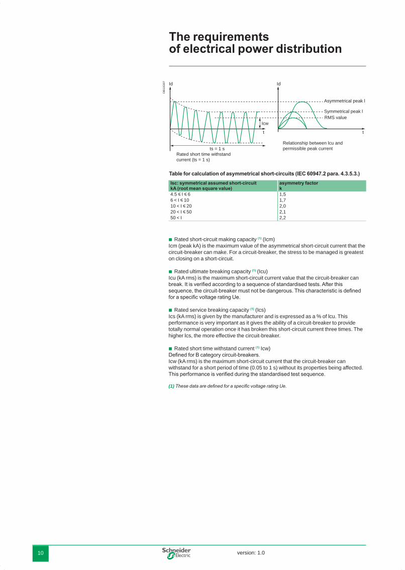
Rated short-circuit making capacity (1) (Icm) Icm (peak kA) is the maximum value of the asymmetrical short-circuit current that the circuit-breaker can make. For a circuit-breaker, the stress to be managed is greatest on closing on a short-circuit.
Rated ultimate breaking capacity (1) (Icu)Icu (kA rms) is the maximum short-circuit current value that the circuit-breaker can break. It is verified according to a sequence of standardised tests. After this sequence, the circuit-breaker must not be dangerous. This characteristic is defined for a specific voltage rating Ue.
Rated service breaking capacity (1) (Ics)Ics (kA rms) is given by the manufacturer and is expressed as a % of lcu. This performance is very important as it gives the ability of a circuit-breaker to provide totally normal operation once it has broken this short-circuit current three times. The higher lcs, the more effective the circuit-breaker.
Rated short time withstand current (1) Icw)Defined for B category circuit-breakers. Icw (kA rms) is the maximum short-circuit current that the circuit-breaker can withstand for a short period of time (0.05 to 1 s) without its properties being affected. This performance is verified during the standardised test sequence.
(1) These data are defined for a specific voltage rating Ue.
b
b
b
b
Table for calculation of asymmetrical short-circuits (IEC 60947.2 para. 4.3.5.3.)
DB
1163
07
Isc: symmetrical assumed short-circuit kA (root mean square value)
asymmetry factor k
4.5 y I y 6 1,56 < I y 10 1,710 < I y 20 2,020 < I y 50 2,150 < I 2,2
t t
IdId
Icw
ts = 1 s
RMS value
Rated short time withstand current (ts = 1 s)
Relationship between lcu andpermissible peak current
Asymmetrical peak l
Symmetrical peak l
The requirements of electrical power distribution
DBTP107_EN_Pint.indd 10 27/02/2008 16:07:21

version: 1.0 11
1.4.3. Circuit-breaker coordinationThe term coordination concerns the behaviour of two devices placed in series in electrical power distribution in the presence of a short-circuit
Cascading or back-up protectionThis consists of installing an upstream circuit-breaker D1 to help a downstream circuit-breaker D2 to break short-circuit currents greater than its ultimate breaking capacity lcuD2. This value is marked lcuD2+D1.Standard IEC 60947-2 recognises cascading between two circuit-breakers. For critical points, where tripping curves overlap, cascading must be verified by tests.
DiscriminationThis consists of providing coordination between the operating characteristics of circuit-breakers placed in series so that should a downstream fault occur, only the circuit-breaker placed immediately upstream of the fault will trip.Standard IEC 60947-2 defines a current value ls known as the discrimination limit such that:
if the fault current is less than this value ls, only the downstream circuit-breaker D2 trips,
if the fault current is greater than this value ls, both circuit-breakers D1 and D2 trip.Just as for cascading, discrimination must be verified by tests for critical points.Discrimination and cascading can only be guaranteed by the manufacturer who will record his tests in tables.
b
b
E45
015a t
IB IcuD2+D1
D2 D1
I
IcuD2
D1
D2
DB
1163
06
overlappingarea
t
IB IcuD1
D2 D1
I
IcuD2
D1
D2
Cascading. Discrimination.
Glossary:lsc(D1): Short-circuit current at the point where D1 is installed,lcuD1: Ultimate breaking capacity of D1.
bb
DBTP107_EN_Pint.indd 11 27/02/2008 16:07:21

version: 1.012
1.5. Summarising table
MSB Level A
Subdistribution switchboard Level B
Final distribution switchboard Level C
Switchboard dataNominal I 1000 to 6300 A 100 to 1000 A 1 to 100 AIsc 50 kA to 150 kA 20 kA to 100 kA 3 kA to 10 kAThermal withstand Icw / EDW
*** * *
Continuity of supply
*** *** **
Circuit-breaker type
High current power circuit-breaker or moulded case circuit-breaker
Moulded case circuit-breaker
Miniature circuit-breaker
Standard IEC 60947-2 b b b (1)
Trip unitthermal magnetic electronic
b
v (2)
b b
product datastandard ln 800 to 6300 A 100 to 630 A 1 to 125 AIcn 50 kA to 150 kA 25 kA to 150 kA 3 kA to 25 kA
Utilisation category B A ALimiting capacity * (3) *** ***
recommended or compulsorypossible
*** important** normal* not very important
(1) For domestic use as per IEC 60898 standard.(2) Possible up to 250 A.(3) Le Sizing of the switchboard at level A means that this characteristic is not very important for standard applications.
bv
The requirements of electrical power distribution
DB
1168
78
0318
87
DB
1172
10

version: 1.0 13
2.1. Limitation
2.1.1. PrinciplesThe assumed fault current lsc is the short-circuit current lsc that would flow, if there were no limitation, at the point of the installation where the circuit-breaker is placed. Since the fault current is eliminated in less than one half-period, only the first peak current (asymmetrical peak l) need be considered. This is a function of the installation fault cos ϕ.
DB
1163
08
t
I
t
Em
t1 t2
U
L
A
ts
Id
asymmetrical
Isc
Reduction of this peak l to limited lL characterises circuit-breaker limitation.
Limitation consists of creating a back-electromotive force opposing the growth of the short-circuit current.
The three decisive criteria guaranteeing the effectiveness of this limitation are:intervention time, i.e. the time ts when the back-electromotive force (bemf)
appears,the rate at which bemf increases,the value of bemf.
The back-electromotive force is the arc voltage Ua due to the resistance of the arc developing between the contacts on separation. Its speed of development depends on the contact separation speed.
As shown in the figure above, as from the time ts when the contacts separate, the back less than the assumed fault current flow through when a short-circuit occurs.
b
bb
Limitation is a technique that allows the circuit-breaker to considerably reduce short-circuit currents.The advantages of limitation are numerous:
attenuation of the harmful effects of short-circuits:
electromagnetic,thermal,mechanical,base of the cascading technique.
b
vvvb
In s
hor
t
The implementation techniques
DBTP107_EN_Pint.indd 13 27/02/2008 16:07:21

version: 1.014
2.1.2. Circuit breaker limitation capacityThe circuit breaker limitation capacity defines the way how it reduces the let through current in short-circuit conditions.
The thermal stress of the limited current is the area (shaded) defined by the curve of the square of the limited current l2sc (t). If there is no limitation, this stress would be the area, far larger, that would be defined by the curve of the square of the assumed current.For an assumed short-circuit current lsc, limitation of this current to 10% results in less than 1% of assumed thermal stress.The cable temperature rise is directly proportional to the thermal stress (1).
Current and thermal stress limitation.
2.1.3. AdvantagesApplication to electrical power distributionLimitation considerably attenuates the harmful effects of short-circuits on the installation.
Harmful effectsof short-circuits
Limitation effects
electromagneticb Reduction of magnetic field, thus:less risk of disturbing neighbouring measurement
instrument. v
mechanicalb Peak current limited, thus:reduced electromagnetic forces,vless risk of deformation or breakage at electrical
contact level. v
thermalb Limited thermal stress (reduction of amplitude and duration of current flow), thus:
temperature rise of conductors less marked,vincreased lifetime of busbar trunking.v
Consequently, limitation contributes to the durability of electrical installations.
(1) On a short-circuit, adiabatic temperature rise of conductors occurs (without heat exchange with the outside due to the speed of the energy supply). The increased temperature for a conductor with a cross-section S is:
is called thermal stress (A2s).
DB
1163
09
assumed transientpeak lsc
limitedpeak lsc
assumed steadypeak lsc
Isc
ttcc
100%
10%
 DB
1163
10
Assumedenergy100%
Limitedenergy< 1%
A2
I2cc
t
K∆θ =0
T
0
T
S2 I2dt where I2dt
The implementation techniques
DBTP107_EN_Pint.indd 14 27/02/2008 16:07:22

version: 1.0 15
Applications to motors Functions
DB
1163
11
isolation andshort-circuitprotection
control
overloadprotectionor thermalprotection
internal motoror specificprotections
Type 1 IEC 60947-4-1
Type 2 IEC 60947-4-1
No risk for the operator. Elements other than contactors and the relay must not be damaged. Isolation must be maintained after an incident.. Before restarting, the motor feeder must be repaired.
No damage or malfunctioning is allowed.Isolation must be maintained after an incident and the motor feeder must be able to operate after a short-circuit. The risk of risque de contactor contact welding is accepted if contacts can be easily separated. Before restarting, a quick inspection is sufficient. Reduced maintenance and rapid resumption of operation.
The following functions must be performed on a motor feeder:
isolation,control,overload protection (specific),short-circuit protection,additional protection.
A motor feeder can be made up of 1, 2, 3 or 4 different items of switchgear.Should a number of devices be associated - most common case - the various functions performed by the switchgear must be coordinated.
Coordination of motor feeder components. Thanks to limitation, the harmful effects of short-circuits on a motor feeder are greatly attenuated. Proper limitation of circuit-breakers ensures easy access to a type 2 coordination as per IEC 60947-4-1, without oversizing of components. This type of coordination guarantees users optimum use of their motor feeders.
bbbbb
Motor feeder.
DBTP107_EN_Pint.indd 15 27/02/2008 16:07:22

version: 1.016
2.1.4. Limitation curvesA circuit-breaker’s limiting capacity is expressed by limitation curves that give:
the limited peak current as a function of the rms current of the assumed short-circuit current.For example: on a 160 A feeder where the assumed lsc is 90 kA rms, the non-limited peak lsc is 200 kA (asymmetry factor of 2.2) and the limited lsc is 26 kA peak.
the limited thermal stress (in A2s) as a function of the rms current of the assumed short-circuit current. For example: on the previous feeder, the thermal stress moves from more than 100 106 A2s to 6 106 A2s.
DB
1163
12
kA
90 kA
200
26
A s2
90
limited peak lsc
assumed rms lsc
limitedthermalstress
assumedrms lsc
peak
kA rms
kA rms
Thermal stress limitation curve.
b
b
Current limitation curve.
The implementation techniques
DBTP107_EN_Pint.indd 16 27/02/2008 16:07:22

version: 1.0 17
2.2. Cascading
Cascading provides circuit-breakers placed downstream of a limiting circuit-breaker with an ìenhancedî breaking capacity. The limiting circuit-breaker helps the circuit-breaker placed downstream by limiting high short-circuit currents. Cascading makes it possible to use a circuit-breaker with a breaking capacity lower than the short-circuit current calculated at its installation point.
2.2.1. Area of application2.2.1.1. Cascading
concerns all devices installed downstream of this circuit-breaker,can be extended to several consecutive devices, even if they are used in different
switchboards.
The installation standards (IEC 60364 or local) stipulate that the upstream device must have an ultimate breaking capacity lcu greater than or equal to the assumed short-circuit current at the installation point.For downstream circuit-breakers, the ultimate breaking capacity lcu to be considered is the ultimate breaking capacity enhanced by coordination.
2.2.1.2. PrinciplesAs soon as the two circuit-breakers trip (as from point lB), an arc voltage UAD1 on separation of the contacts of D1 is added to voltage UAD2 and helps, by additional limitation, circuit-breaker D2 to open.The implementation techniques.
E45
015c
t (s)
IB Icu(D2 + D1)
D2 D1
I
Icu(D2)
E45
217
D1
D2 I
t1
Icc
UAD2IB
t1' t2
UAD1
UAD2
UAD1
t (ms)
bb
Cascading is used to: make savings,simplify choice of protection devices,
by using circuit-breakers with standard performance.
bb
In s
hor
t
DBTP107_EN_Pint.indd 17 27/02/2008 16:07:22

version: 1.018
The association D1 + D2 allows an increase in performance of D2 as shown in figure 2:limitation curve D2,enhanced limitation curve of D2 by D1,Icu D2 enhanced by D1.
In actual fact, in compliance with the recommendations of IEC 60947-2, manufacturers give directly and guarantee lcu enhanced by the association of D1 + D2.
DB
1163
13
IcuD2
Isc (D)
I
1I
D1
D2
D1 helps D2 to break the currentlimitation of D2 enhanced by D1limitation of D2limitation of D1
IcuD2/enhanced
2.2.1.3. AdvantagesCascading allows benefit to be derived from all the advantages of limitation. Thus, the effects of short-circuit currents are reduced, i.e.:
electromagnetic effects,electrodynamic effects,thermal effects.
Installation of a single limiting circuit-breaker results in considerable simplifications and savings for the entire downstream installation:
simplification of choice of devices by the cascading tables,savings on downstream devices. Limitation enables circuit-breakers with standard
performance to be used.
bbb
bb
bbb
The implementation techniques
DBTP107_EN_Pint.indd 18 27/02/2008 16:07:22

version: 1.0 19
2.3. Discrimination
2.3.1. General information
2.3.1.1. PrincipleReminder (see paragraph 1.4. "standard IEC 60947-2”).Discrimination consists of providing coordination between the operating characteristics of circuit-breakers placed in series such that should a downstream fault occur, only the circuit-breaker placed immediately upstream of the fault will trip. A discrimination current ls is defined such that:
lfault > ls: both circuit-breakers trip,lfault < ls: only D2 eliminates the fault.
DB
1163
14
D1
D2
0 IsD2IrD1 and D2trip
I faultD2 onlytrips
I fault
Discrimination qualityThe value ls must be compared with assumed lsc(D2) at point D2 of the installation.
total discrimination: ls > lsc(D2); discrimination is qualified as total, i.e. whatever the value of the fault current, D2 only will eliminate it.
partial discrimination: ls < lsc(D2); discrimination is qualified as partial, i.e. up to ls, only D2 eliminates the fault. Beyond ls, both D1 and D2 open.
Manufacturer’s dataIn actual fact, manufacturers give discrimination quality intrinsically, i.e.:
total discrimination, if ls is equal to lcuD1 (the association will never be able to see a fault current greater than this value),
partial discrimination, limited to ls. This value ls can nevertheless be greater than lsc(D2). Seen by the user, discrimination is then tota.
Glossarylsc(D1): Short-circuit current at the point where D1 is installed,lcuD1: Ultimate breaking capacity of D1.
bb
b
b
b
b
bb
Discrimination of protection devices is a key factor in continuity of supply.Discrimination is:
partial, or total,
according to the characteristics of the association of protection devices. The discrimination techniques implemented are:
current, time,logic.
Discrimination can be optimised by use of limiting downstream circuit-breakers.
bb
bbb
In s
hor
t
DBTP107_EN_Pint.indd 19 27/02/2008 16:07:22

version: 1.020
2.3.2. Technical discriminationsCurrent discriminationThis technique is directly linked to the staging of the Long Time (LT) tripping curves of two serial-connected circuit-breakers.
E45
213b
D1
D2
Isd 2 Isd 1Ir2 Ir1
t D2 D1
I
The discrimination limit ls is:ls = lsd2 if the thresholds lsd1 and lsd2 are too close or merge,ls = lsd1 if the thresholds lsd1 and lsd2 are sufficiently far apart.
As a rule, current discrimination is achieved when:Ir1 / Ir2 < 2,Isd1 / Isd2 > 2.
The discrimination limit is:Is = Isd1.
Time discriminationThis is the extension of current discrimination and is obtained by staging over time of the tripping curves. This technique consists of giving a time delay of t to the Short Time (ST) tripping of D1.
DB
1021
05
���
��
��
����� �������� ����
��
���� �� ��
��
The thresholds (lr1, lsd1) of D1 and (lr2, lsd2) comply with the staging rules of current discrimination. The discrimination limit ls of the association is at least equal to li1, the instantaneous threshold of D1.
--
--
-
Discrimination qualityDiscrimination is total if ls > lsc(D2), i.e. lsd1 > lsc(D2). This normally implies:
a relatively low level lsc(D2),a large difference between the ratings of circuit-breakers D1 and D2.
Current discrimination is normally used in final distribution.
vv
Discrimination qualityDiscrimination is total if ls > lsc(D2), i.e. lsd1 > lsc(D2). This normally implies:
a relatively low level lsc(D2),a large difference between the ratings of circuit-breakers D1 and D2.
Current discrimination is normally used in final distribution.
vv
The implementation techniques
DBTP107_EN_Pint.indd 20 27/02/2008 16:07:22

version: 1.0 21
Discrimination qualityThere are two possible applications:
on final and/or intermediate feedersA category circuit-breakers can be used with time-delayed tripping of the upstream circuit-breaker. This allows extension of current discrimination up to the instantaneous threshold li1 of the upstream circuit-breaker: ls = li1.If lsc(D2) is not too high - case of a final feeder - total discrimination can be obtained.
on the incomers and feeders of the MSBAt this level, as continuity of supply takes priority, the installation characteristics allow use of B category circuit-breakers designed for time-delayed tripping. These circuit-breakers have a high thermal withstand (lcw u 50% lcn for t = 1s): Is = Icw1.Even for high lsc(D2), time discrimination normally provides total discrimination: Icw1 > Icc(D2).
b
b
Note : Use of B category circuit-breakers means that the installation must withstand high electrodynamic and thermal stresses.Consequently, these circuit-breakers have a high instantaneous threshold li that can be adjusted and disabled in order to protect the busbars if necessary.
Enhancement of current and time discriminationlimiting downstream circuit-breakers.
Use of a limiting downstream circuit-breaker enables the discrimination limit to be pushed back.
DB
1163
15
Ic
ILdId
Id
non-limiting
short-circuitlimiter
Isc (D2)
In fact, when referring to the figure, a fault current ld will be seen by D1:
equal to ld for a non-limiting circuit-breaker,equal to lLd y ld for a limiting circuit-breaker.
The limit of current and time discrimination ls of the association D1 + D2 is thus pushed back to a value that increases when the downstream circuit-breaker is rapid and limiting.
b
bb
Discrimination qualityUse of a limiting circuit-breaker is extremely effective for achievement of total discrimination when threshold settings (current discrimination) and/or the instantaneous tripping threshold (time discrimination) of the upstream circuit-breaker D1 are too low with respect to the fault current ld in D2 - lsc(D2).
DBTP107_EN_Pint.indd 21 27/02/2008 16:07:22

version: 1.022
Logic discrimination or "Zone Selective Interlocking (ZSI)"
DB
1168
82
pilot wire
interlockingorder
interlockingorder
D1
D2
D3
Logic discrimination.
This type of discrimination can be achieved with circuit-breakers equipped with specially designed electronic trip units (Compact, Masterpact): only the Short Time Protection (STP) and Ground Fault Protection (GFP) functions of the controlled devices are managed by Logic Discrimination. In particular, the Instantaneous Protection function - inherent protection function - is not concerned.
Settings of controlled circuit-breakerstime delay: there are no rules, but staging (if any)of the time delays of time
discrimination must be applied (∆tD1 u ∆tD2 u ∆tD3),
thresholds: there are no threshold rules to be applied, but natural staging of the protection device ratings must be complied with (IcrD1 u IcrD2 u IcrD3).
Note : This technique ensures discrimination even with circuit-breakers of similar ratings.
PrinciplesActivation of the Logic Discrimination function is via transmission of information on the pilot wire:
ZSI input:low level (no downstream faults): the Protection function is on standby with a
reduced time delay (y 0,1 s),high level (presence of downstream faults): the relevant Protection function moves
to the time delay status set on the device.ZSI output:low level: the trip unit detects no faults and sends no orders,high level: the trip unit detects a fault and sends an order.
OperationA pilot wire connects in cascading form the protection devices of an installation (see figure showing logic discrimination). When a fault occurs, each circuit-breaker upstream of the fault (detecting a fault) sends an order (high level output) and moves the upstream circuit-breaker to its natural time delay (high level input). The circuit-breaker placed just above the fault does not receive any orders (low level input) and thus trips almost instantaneously.
b
b
bv
v
bvv
The implementation techniques
Discrimination qualityRecommended and extensively used in the USA, this technique enables:
easy achievement as standard of discrimination on 3 levels or more,elimination of important stresses on the installation, relating to time-delayed
tripping of the protection device, in event of a fault directly on the upstream busbars. All the protection devices are thus virtually instantaneous,
easy achievement of downstream discrimination with non-controlled circuit-breakers.
vv
v
DBTP107_EN_Pint.indd 22 27/02/2008 16:07:22

version: 1.0 23
2.4. The discrimination rules
2.4.1. General discrimination rulesOverload protection For any overcurrent value, discrimination is guaranteed on overload if the non-tripping time of the upstream circuit-breaker D1 is greater than the maximum breaking time of circuit-breaker D2.The condition is fulfilled if the ratio of Long Time (LT) and Short Time (ST) settings is greater than 2. The discrimination limit ls is at least equal to the setting threshold of the upstream Short Time (ST) time delay.
Short-circuit protectiontime discrimination
Tripping of the upstream device D1 is time delayed by ∆t.The conditions required for current discrimination must be fulfilled.The time delay ∆t of the upstream device D1 must be sufficient for the
downstream device to be able to eliminate the fault.Time discrimination increases the discrimination limit ls up to the instantaneous tripping threshold of the upstream circuit-breaker D1.Discrimination is always total if circuit-breaker D1:
is of category B,has an lcw characteristic equal to its lcu.
Discrimination is total in the other cases if the instantaneous tripping threshold of the upstream circuit-breaker D1 is greater than the assumed lsc in D2.
logic discriminationDiscrimination is always total.
general caseThere are no general discrimination rules.
The time/current curves ìclearlyî supply a value of lsc (limited or assumed) less than the Short Time tripping of the upstream circuit-breaker; discrimination is then total.
DB
1163
17
Isd1
t
Is
Isd1Ir2
I t
IIs
IIr2 currentdiscrimination time
discrimination
b
vv
--
b
b
v
If this is not the case, only tests can indicate discrimination limits of coordination, in particular when circuit-breakers are of the limiting type. The discrimination limit ls is determined by comparison of curves:
in tripping energy for the downstream circuit-breaker,
in non-tripping energy for the upstream circuit-breaker.The potential intersection point of the curves gives the discrimination limit ls.
The manufacturers indicate in tables the tested performance of coordination..
v
v
DBTP107_EN_Pint.indd 23 27/02/2008 16:07:23

version: 1.024
2.5. Earth leakage protection discrimination
According to the earthing system, discrimination only uses coordination of overcurrent protection devices. When the insulation fault is treated specifically by earth leakage protection devices (e.g. in the TT system), discrimination of the residual current devices (RCDs) with one another must also be guaranteed.
Discrimination of earth leakage protection devices must ensure that, should an insulation fault occur, only the feeder concerned by the fault is de-energised.The aim is to optimise energy availability.
There are two types of earth leakage protection discrimination.
2.5.1. Vertical discriminationIn view of requirements and operating standards, discrimination must simultaneously meet both the time and current conditions.
DB
1163
18
RCD
RCD
Da
Db
Vertical discrimination.
Current condition:The RCD must trip between I∆n and I∆n/2, I∆n where ln is the declared operating current. There must therefore exist a minimum ratio of 2 between the sensitivities of the upstream device and the downstream device. In practice, the standardised values indicate a ratio of 3.
Time condition:The minimum non-tripping time of the upstream device must be greater than the maximum tripping time of the downstream device for all current values.
Note : The tripping time of RCDs must always be less than or equal to the time specified in the installation standards to guarantee protection of people against indirect contacts.
The implementation techniques
DBTP107_EN_Pint.indd 24 27/02/2008 16:07:23

version: 1.0 25
For the domestic area (M9), standards IEC 61008 (residual current circuit-breakers) and IEC 61009 (residual current devices) define operating times. The values in the table correspond to curves G and S. Curve G (General) correspond to non-delayed RCDs and S (Selective) to those that are voluntarily delayed.
E45
046
��
��
�����
���
���
���
� � � ��
��� �
���������
�
������
Operating time curves G and S.
Standardised values of operating timeType In
AI∆n A
Standardised values of operating time and non-operating time (in seconds) at: I∆n 2I∆n 5I∆n 500 A
general instantaneous
all valeurs
all valeurs
0.3 0.15 0.04 0.04 maximum operating time
selective > 25 > 0.030 0.5 0.2 0.15 0.15 maximum operating time
0.13 0.06 0.05 0.04 minimum non operating time
2.5.2. Horizontal discriminationSometimes known as circuit selection, it allows savings at the supply end of the installation of an RCD placed in the cubicle if all its feeders are protected by RCDs. Only the faulty feeder is de-energised, the devices placed on the other feeders do not see the fault.
DB
1163
19
RCD RCD
Horizontal discrimination.
DBTP107_EN_Pint.indd 25 27/02/2008 16:07:23

version: 1.026
Discrimination and cascading can only be guaranteed by the manufacturer who will record his tests in tables.
In s
hor
t2.6. Coordination of protection devices installation standards
Installation standard IEC 60364 governs electrical installations of buildings. National standards, based on this IEC standard, recommend good coordination between the protection switchgear. They acknowledge the principles of cascading and discrimination of circuit-breakers based on product standard IEC 60947-2. Product standards IEC 60947-2In appendix A, standard IEC 60947-2 recognises and defines coordination between circuit-breakers (see paragraph 1.4 page 11). In particular, it defines the tests to be performed.
discriminationThis is normally studied on a theoretical level. For critical points where tripping curves overlap, it must be verified by tests. It is guaranteed by the manufacturer who will record the value of ls (discrimination limit) in tables.
cascading or coordination of the back-up protection deviceThe standard indicates the measurements to be taken to verify this coordination.
Verification by comparison of characteristicsIn practical cases, this type of verification is sufficient. It must be clearly proved that the lcuD2 of the association is compatible with the maximum energy l2t acceptable by D2.
Verification by testsCascading is normally verified by tests for critical points. The tests are performed with an upstream circuit-breaker D1 with a maximum overcurrent setting and a downstream circuit-breaker D2 with a minimum setting. The test results (breaking capacities enhanced by cascading) are in a table and guaranteed by the manufacturer.
Installation standardsNational installation standards specify the implementation of these principles as per the earthing system considered, in accordance with standard IEC 60364.
DiscriminationDiscrimination is defined and established for all earthing systems used and types of fault (overload, short-circuit, insulation fault). However, in event of an insulation fault in the IT system, the advantage of continuity of supply is provided by the actual system that tolerates the 1st fault. This advantage must be maintained by a search and rapid elimination of this fault.
CascadingOn the other hand, cascading rules are given for a TN or TT type earthing system.
Basic rules in TT system:Cascading rules cannot apply for an IT system due to the double insulation fault. The following rules must be implemented:
the circuit-breaker must have a breaking capacity that is greater than or equal to the three-phase short-circuit current at the point considered,
in event of a assumed double fault, it is laid down that the double fault short-circuit current will be at most:
15% of three-phase lsc for a three- phase lsc y 10 000 A,25% of three-phase lsc for a three-phase lsc > 10 000 A.
b
b
v
v
b
b
vv
The implementation techniques
DBTP107_EN_Pint.indd 26 27/02/2008 16:07:23

version: 1.0 27
E51
174
TT system.
L1L2L3NPE
TN system.
L1L2L3NPE
IT system.
Note : Standard IEC 60364 defines 3 types of earthing systems. In short: TT: The neutral point of the LV transformer is earthed.
The equipment frames are connected to a separate earth.TN: The neutral point of the LV transformer and the equipment frames are connected to the
same earth.IT: The neutral point of the LV transformer is unearthed.
The equipment frames are earthed.The earthing systems (and associated automatic breaking techniques) have been defined to guarantee protection of people against indirect contacts.
b
b
b
E51
122
E51
175
L1L2L3N
PE
DBTP107_EN_Pint.indd 27 27/02/2008 16:07:23

version: 1.028
The Merlin Gerin and Telemecanique circuit-breaker ranges cover all the requirements of LV electrical power distribution from 0.5 to 6300 A, i.e.:
the Merlin Gerin 630 to 6300 A Masterpact NT and NW power circuit-breaker ranges,
the range of Compact moulded case circuit-breakers (MCCB):Compact NS from 630 to 3200 ACompact NSX from 100 to 630 Athe 0.5 to 125 A Multi 9 NG125, C60, DPN miniature circuit-breaker ranges, the Telemecanique Integral/GV2/GV7 motor protection circuit-breaker ranges.
These products meet product standards IEC 60947-2.
The Merlin Gerin and Telemecanique distribution and motor protection circuit-breaker ranges have been developed coherently. Their coordination has been tested as per IEC 60947-2 and is guaranteed by Schneider Electric. The complete tables giving coordination, cascading and discrimination of circuit-breakers are available.
b
bvvbb
The Schneider Electric choice
DBTP107_EN_Pint.indd 28 27/02/2008 16:07:23

version: 1.0 29
3.1. For power circuit-breakers
The technologies of Schneider Electric’s Masterpact ranges ideally meet the discrimination needs at the supply end of the installation as well as specific limitation requirements relating to certain applications.
3.1.1. The selective pole
3.1.1.1. The selective pole technologyImportant discrimination requires enhancement of the switchgear’s electrodynamic withstand, using the own current compensation effect.
Electromagnetic compensation.
This technology is used in all the Masterpact NT and NW except for performance L1 of the Masterpact NT that uses a limiting pole technology.
The 150 kA/415 V breaking capacity performance in the small volume of the Masterpact NT requires a different pole.
The limiting pole technologyA high limiting capacity is enabled by:
a fixed pole with current loop and magnetic U,one axis of the moving pole positioned at its end.
3.1.2. Technical innovations of new Masterpact for better performances 3.1.2.1. Masterpact NT and NW N1 and H1This performance is ideal on the most common industrial and large tertiary sites (lsc < 65 kA). It guarantees total discrimination with the downstream Compact NS circuit-breakers.
For this performance, breaking capacity is equal to thermal withstand lcs = lcw.
This allows the switchgear to withstand the maximum short-circuit current throughout the short time delay.
DB
1163
20
42 kA I65 kA
NT H1 NW H1
total time discrimination
Icu = Ics = electrodynamic withstand Icw
3.1.2.2. Masterpact NW H2When the short-circuit level at the device installation point is greater than its thermal withstand, its breaking capacity must be greater than its thermal withstand lcs > lcw.
An internal protection is now required to prevent the switchgear being damaged. This is an instantaneous tripping device set in the factory to a threshold just below electrodynamic withstand (EDW).
bb
E56
816
1/3
2/3
i
iA
i
Frdfm
Fm
Contact pressure is proportional to l2 in the loop.
DBTP107_EN_Pint.indd 29 27/02/2008 16:07:23

version: 1.030
DB
1163
21
EDW
t
Isc
Accuracy zoneof theinstantaneoustripping threshold(±10 %)
DB
1163
22
85 kA I100 kA
Ics = Icu
NW H2
Icw = thermal withstand = self-protection DIN threshold
maximum time discrimination
Limited time discrimination
Widespread use of air current transformers enables, thanks to more accurate measurement (no saturation) the thermal withstand threshold to be approached, thus markedly enhancing the discrimination level by delaying instantaneous tripping.
For large industrial sites (lsc < 100 kA), this performance guarantees total discrimination with the downstream Compact NS.
The Schneider Electric choice
Accuracy zone of the instantaneous tripping threshold (±10 %).
DBTP107_EN_Pint.indd 30 27/02/2008 16:07:23

version: 1.0 31
3.1.2.3. Masterpact NW H3Just as for the Masterpact H2, the level of performance lcs > lcw also requires calibration of instantaneous tripping.
In order to break an assumed fault current of 150 kA, very early action is required. It is impossible to wait for passage of the first fault current wave as the device’s thermal withstand is far lower.
The technology of the electronic measurement channel associated with the mechanical action of the tripping coil does not allow a sufficiently fast reaction. The technology used in Masterpact NW circuit-breakers has been patented.
When a high short-circuit current appears, it creates an electromagnetic force that pushes the pole and moves it apart. The pole movement activates a catch by means of a kinematic chain. The movement of this catch directly releases the pole shaft before intervention of the electronic measurement chain.
DB
1163
23 Half moon activating the pole shaft
Effort sensor
Kinematic chain
This tripping by mechanical system occurs at the same time as the electronic measurement chain that will confirm circuit-breaker opening and indicate the front face fault.This system allows:
a high thermal withstand to be maintained: lcw = 65 kA 1s,beyond lcw, an ultra fast tripping guaranteeing an lcu up to 150 kA.
This performance is ideal for multisource installations with a high short-circuit current (> 100 kA) on the main busbar and for which continuity of supply is essential. Discrimination with the downstream Compact NS is total as standard.
3.1.2.4. Masterpact NW and NT L1The Masterpact NW L1 combines all performances:
a breaking capacity up to 200 kA/400 V for the UL range,a thermal withstand of 37 kA/400 V,an important limiting capacity (NW L1 assumed lsc = 390 kA to 380/415 V, limited
lsc = 170 kÂ).
It therefore uses the technologies described above:selective pole like the other switchgear in order to reach a thermal withstand
of 30 kA/400 V,automatic unlatching of the circuit breaker operating mechanism to produce ultra
fast tripping.
bb
bbb
b
b
DBTP107_EN_Pint.indd 31 27/02/2008 16:07:24

version: 1.032
To obtain a high limiting capacity, the fixed pole has been modified. This modification has been patented.
Limiting capacity depends on the arc voltage created between the fixed pole and the moving pole on opening. It must be established early on and quickly increase to a high value.
DB
1163
24
t
t
UM
ts
I
U
EM
Ua
e
Prospectiveshort-circuitcurrent
Limited current
Total breaking time
Intervention time
For this purpose, repulsion force must be increased and arc projection encouraged in the arc chute.
Use of a U-shaped current loop to increase the repulsion force.
Use of a magnetic U around the fixed pole to concentrate field lines and project the arc in the arc chute, early on, quickly and high.
DB
1163
25
Magnetic U
b
b
The Schneider Electric choice
DBTP107_EN_Pint.indd 32 27/02/2008 16:07:24

version: 1.0 33
DB
1168
83
Ua
Arc chute
Magnetic U
U-shapedcurrent loop
On a high short-circuit, the poles open very slightly and the magnetic U then projects the arc in the arc chutes. The fault current is diverted. The automatic unlatching of the circuit breaker operating mechanism then quickly opens the circuit-breaker.
This performance meets the limitation needs of fault currents while at the same time guaranteeing an unmatched level of discrimination of 37 kA for this circuit-breaker type.
The Masterpact NT L1 uses a limiting pole that guarantees quick opening on a high short-circuit current.
Its limiting capacity is very great for this circuit-breaker type. NT L1 prospective lsc = 390 kA and limited lsc = 75 kÂ.
To enhance breaking performance and obtain a high short-circuit current limitation on devices theoretically not very limiting, a trip unit is used, not based on the instantaneous value of the current but on a drift whose peculiarity is not to trip on the first fault current half wave. When a short-circuit current appears, the downstream circuit-breaker opens as soon as the fault current is greater than its tripping threshold and eliminates the fault in less than one half-wave. The upstream Masterpact NT L1 does not trip but its contacts are repulsed, thus limiting stresses on the circuit.
DBTP107_EN_Pint.indd 33 27/02/2008 16:07:24

version: 1.034
3.2. For moulded case circuit-breakers (MCCB)
The Merlin Gerin and Telemecanique moulded case circuit-breaker (MCCB) ranges are designed to provide users with maximum energy availability. The MCCB:
give an optimum response to discrimination problems, are very limiting, even on high short-circuits, in order to drastically reduce stresses
on intermediate distribution.
The 100 to 630 A Compact NSX range is mainly used:to protect intermediate distribution, to protect lines supplying large loads.
This range implements an innovating technique: roto-active breaking.
This high current limiting technique uses a new tripping energy, pressure, resulting from arc energy.Its operation is described below:
Each circuit-breaker pole has an enclosure in which a rotating contact generates, by electromagnetic repulsion, two serial arcs on occurrence of the short-circuit current.
A piston and spring device uses the pressure from arc energy to cause - beyond a certain threshold (roughly 25 ln) - a reflex tripping, roughly 3 ms after contact repulsion.
Up to this threshold, pressure is not sufficient to cause tripping and arc impedance limits the short-circuit current.
Beyond this threshold, breaking is very quick (1 ms) and limits still further the short-circuit current.The enclosure parts are sized to match circuit-breaker size. Consequently, limitation is greatest when rating is smallest.This technique provides Compact NSX with an outstanding limiting capacity and thus with increased discrimination possibilities.This technique is also very useful for limiting stresses on electrical power distribution.
3.2.1. Trip unitsThe Compact NSX are equipped with a thermal magnetic or electronic type trip unit. Setting of the Long Time (LT) thresholds ensures current discrimination.Short Time (ST) protection has as standard a mini time delay of 5 to 7 ms according to sizes allowing time discrimination for short-circuits of average value beyond the Short Time (ST) tripping threshold of the upstream circuit-breaker D1.
bb
bb
b
b
b
b
Arc chute
Short-circuitcurrent
Piston
The Schneider Electric choice
DB
1138
84
Arc
Arc
Fixedcontact
Movingcontact
Breakingenclosure
Arc chute
Fixedcontact
Arc chute
DB
1163
28
Roto-active breaking: repulsion of contacts. Roto-active breaking: tripping by pressure.
DBTP107_EN_Pint.indd 34 27/02/2008 16:07:24

version: 1.0 35
3.3. For miniature circuit-breakers MCB
The Merlin Gerin Multi 9 Miniature circuit-breaker ranges have the necessary performance and characteristics to meet final distribution requirements:
E45
221 a nominal rating of 0.5 to 125 A,
a breaking capacity of up to 50 kA as per IEC 60947-2,
tripping curves B, C, D and MA,simple, safe installation system on DIN rail,Vigi module can easily be clipped onto the protection
devices.The Multi 9 circuit-breakers are designed according to magnetic actuator principles, thus allowing very quick development of arc voltage.
bb
bbb
��
�
�
�
DBTP107_EN_Pint.indd 35 27/02/2008 16:07:24
version: 1.036
3.4. The discrimination rules from 1 to 6300 A
3.4.1. General discrimination rules (in distribution)
3.4.1.1. Overload protectionupstream and downstream circuit-breakers equipped with a thermal magnetic trip unit.
The current discrimination of Merlin Gerin and Telemecanique circuit-breakers is provided if the ratio of the tripping thresholds:
thermal is greater than 1.6,magnetic is greater than 2.upstream circuit-breaker equipped with an electronic trip unit and downstream
circuit-breaker equipped with a thermal magnetic trip unit.Current discrimination of the Merlin Gerin and Telemecanique circuit-breakers is provided if the ratio of the tripping thresholds:
Long Time (LT) and thermal is greater than 1.6 (1) to 2,5, Short Time (ST) and magnetic is greater than 1.5.upstream and downstream circuit-breakers equipped with an electronic trip unit.
Current discrimination of the Merlin Gerin and Telemecanique circuit-breakers is provided if the ratio of the tripping thresholds:
Long Time (LT) is greater than 1.2 (1) to 1.6, Short Time (ST) is greater than 1.5.
(1) Upstream trip unit equipped with a time-delayable LT threshold.
3.4.1.2. Short-circuit protectiontime discrimination
Time discrimination of Merlin Gerin and Telemecanique circuit-breakers is provided as soon as there is a difference of one time delay band between the upstream and the downstream device.
logic discriminationDiscrimination is always total.
3.4.2. Discrimination rules for Masterpact NT and NW
3.4.2.1. Masterpact NT and NW of the H1 and N1 typeTime discrimination is always total with a Masterpact N1 or H1 upstream (lcw = lcu) regardless of the circuit-breaker placed downstream.
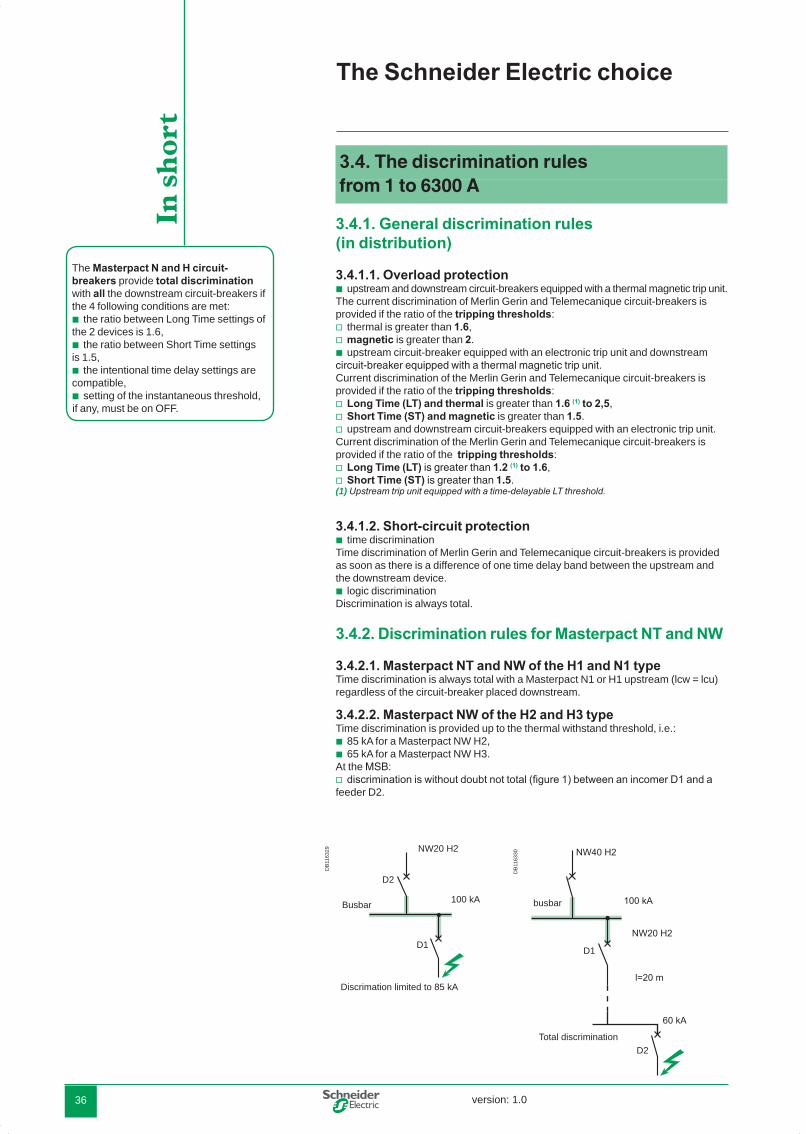
3.4.2.2. Masterpact NW of the H2 and H3 typeTime discrimination is provided up to the thermal withstand threshold, i.e.:
85 kA for a Masterpact NW H2,65 kA for a Masterpact NW H3.
At the MSB:discrimination is without doubt not total (figure 1) between an incomer D1 and a
feeder D2.
b
vvb
vvv
vv
b
b
bb
v
The Schneider Electric choice
The Masterpact N and H circuit-breakers provide total discrimination with all the downstream circuit-breakers if the 4 following conditions are met:
the ratio between Long Time settings of the 2 devices is 1.6,
the ratio between Short Time settings is 1.5,
the intentional time delay settings are compatible,
setting of the instantaneous threshold, if any, must be on OFF.
b
b
b
b
In s
hor
t
D1
D2
busbar
Total discrimination
DB
1163
29
Busbar
Discrimation limited to 85 kA
D1
D2
NW20 H2
100 kA
DB
1163
30
DBTP107_EN_Pint.indd 36 27/02/2008 16:07:24
version: 1.0 37
3.4.3. "Natural" discrimination rules between Compact NSX
3.4.3.1. Discrimination between distribution circuit-breakersWith Compact NSX, simple discrimination rules can be drawn up due to the new implementation techniques.
3.4.3.2. Overload protection: current discriminationAs in the general case, current discrimination between Compact NSX is provided if the ratio of the tripping thresholds:
Long Time (LT) is greater than 1.2 to 2.5,Short Time (ST) is greater than 1.5 to 2,
according to the types of trip units equipping the devices.
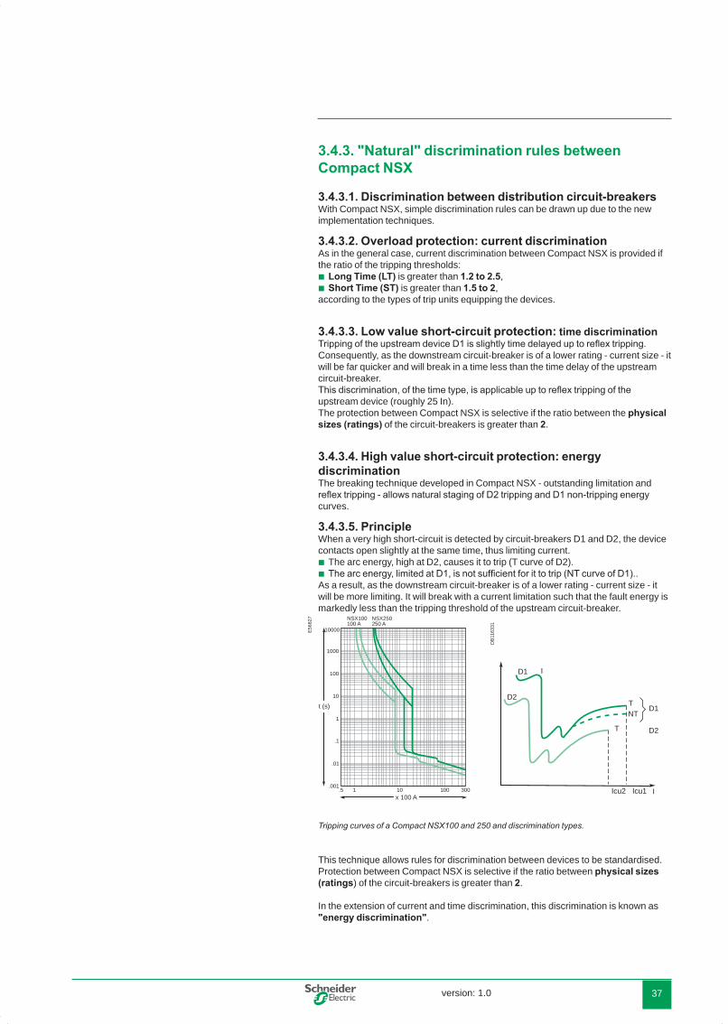
3.4.3.3. Low value short-circuit protection: time discriminationTripping of the upstream device D1 is slightly time delayed up to reflex tripping. Consequently, as the downstream circuit-breaker is of a lower rating - current size - it will be far quicker and will break in a time less than the time delay of the upstream circuit-breaker.This discrimination, of the time type, is applicable up to reflex tripping of the upstream device (roughly 25 In).The protection between Compact NSX is selective if the ratio between the physical sizes (ratings) of the circuit-breakers is greater than 2.
3.4.3.4. High value short-circuit protection: energy discriminationThe breaking technique developed in Compact NSX - outstanding limitation and reflex tripping - allows natural staging of D2 tripping and D1 non-tripping energy curves.
3.4.3.5. PrincipleWhen a very high short-circuit is detected by circuit-breakers D1 and D2, the device contacts open slightly at the same time, thus limiting current.
The arc energy, high at D2, causes it to trip (T curve of D2).The arc energy, limited at D1, is not sufficient for it to trip (NT curve of D1)..
As a result, as the downstream circuit-breaker is of a lower rating - current size - it will be more limiting. It will break with a current limitation such that the fault energy is markedly less than the tripping threshold of the upstream circuit-breaker.
Tripping curves of a Compact NSX100 and 250 and discrimination types.
This technique allows rules for discrimination between devices to be standardised.Protection between Compact NSX is selective if the ratio between physical sizes (ratings) of the circuit-breakers is greater than 2.
In the extension of current and time discrimination, this discrimination is known as "energy discrimination".
bb
bb
Icu1Icu2 I
D1
D2
TNT
T
D2
D1 II2 t
E56
827
x 100 A
t (s)
10000
NSX100100 A
NSX250250 A
1000
100
10
1
.1
.01
.001.5 1 10 100 300
DB
1163
31
DBTP107_EN_Pint.indd 37 27/02/2008 16:07:24

version: 1.038
3.4.4 Discrimination enhanced by cascading with Compact NSXWith traditional circuit-breakers, when cascading is implemented between two devices, discrimination is obtained by tripping of the upstream circuit-breaker D1 to help downstream circuit-breaker D2 to break the current. The discrimination limit has a value ls at most equal to the breaking capacity lcuD2 of the downstream circuit-breaker. In the case of Compact NSX type circuit-breakers, the breaking technique implemented on high short-circuit currents increases the discrimination limit.
The Compact NSX downstream D2 sees a very high short-circuit current. Reflex tripping causes it to trip very quickly (< 1 ms) with a very great limitation of the fault current.
The Compact NSX upstream D1 sees a very limited fault current. This current generates repulsion of the contacts/CR curve, resulting in an arc voltage limiting still further the short-circuit current. However arc pressure is not sufficient to cause reflex tripping.Thus the Compact NSX D1 helps the Compact NSX D2 to break the current without tripping. The discrimination limit ls can exceed the breaking capacity lcuD2 of the downstream circuit-breaker and reach the breaking capacity enhanced by cascading.
Discrimination then becomes total with an optimised device cost.
DB
1163
33 I t
Icu1Icu2
Currentdiscrimination
Timediscrimination
Energydiscrimination
TNT CR
T
Discrimination enhanced by cascading: curves.
b
b
The Schneider Electric choice
UA D2
UA D1
D1
D2ID/IN2
PD2
ID/IN1
t
t
t
t
ts t's
PD1
ts
ts t's
Reflexe
Reflexe
DB
1163
32
Discrimination enhanced by cascading: principle. Advantage of total discrimination as standard with Compact NSXThe immediate advantage is making total discrimination with Compact NSX natural as soon as:
staging of the LT and ST settings is greater than or equal to 1.6,staging of the nominal device ratings is greater than or equal to 2.5.
The figure above illustrates the three types of discrimination.
vv
DBTP107_EN_Pint.indd 38 27/02/2008 16:07:25

version: 1.0 39
3.4.5. Specific applications
3.4.5.1. Comparison with fusesThis rule can be compared with that used for fuse combinations when the ratio of the current ratings must be greater than 1.6.However, compared with fuse combinations:
distribution circuit-breaker,the enhanced discrimination tables, depending on test results, often make it
possible to come down to comparable ratios,the possibility of obtaining discrimination and cascading with downstream circuit-
breakers (enhanced discrimination),motor protection circuit-breaker,motor protection circuit-breakers are ideally sized for the motor rating, whereas
the fuse must be oversized with respect to motor nominal rating.
The combination benefits from all the possibilities offered by the additional integrated functions relating to circuit-breakers. The discrimination ratio is then equivalent.
In this sense, the Compact NSX combine the following: qualities of fuses with respect to high short-circuits,qualities naturally greater for treating overload faults and low value short-circuits,
discrimination rules,advantages relating to functional wealth and the communication potential of
circuit-breakers.
3.4.5.2. Discrimination between a distribution circuit-breaker and a protection circuit-breakerThe qualities of the Compact NSX enable them to be used in motor protection.
E45
032
M
D2
MM
D1
Discrimination of circuit-breakers in motor protection.
3.4.6. SummaryThe following table summarises the conditions to be met to obtain total discrimination.
bb
b
bb
bb
b
D1 Application D2 Ratio between Ratio between upstream and downstream settingsnominal device rating Thermal protection Magnetic protection
TM Distribution TM or Multi 9 u 2,5 u 1,6 u 2Micrologic u 2,5 u 1,6 u 1,5
Motor MA + separate thermal relay u 3 u 2motor thermal magnetic u 3 u 2
Micrologic Distribution TM or Multi 9 u 2,5 u 1,6 u 1,5Micrologic u 2,5 u 1,2 u 1,5
Motor MA + separate thermal relay u 3 u 1,5motor thermal-magnetic u 3 u 1,5Micrologic u 1.3 u 1,5
DBTP107_EN_Pint.indd 39 27/02/2008 16:07:25

version: 1.040
4.1. Discrimination tables
The tables in the ìTechnical additionsî part show the discrimination possibilities of the Merlin Gerin circuit-breakers with one another.Depending on whether or not there is cascading, the results come from a comparison of characteristics or tests.
4.1.1.1. Conditions of useConditions of use are specified: circuit-breakers can be used in distribution or motor protection.
4.1.1.2. Reading the tablesLes The shaded boxes and boxes containing a “T” correspond to total discrimination between the relevant upstream and downstream circuit-breakers, in the conditions of use specified in the “Technical additions” part. For the other boxes, discrimination is either partial (indicated discrimination limit) or there is no discrimination (boxes with no value mentioned).
4.1.1.3. Tables of discrimination enhanced by cascading with Compact NSX With Compact NSX type circuit-breakers, the cascading implemented between two devices increases the discrimination limit. This can consequently reach the breaking capacity enhanced by cascading and discrimination then becomes total. This is expressed in ìenhancedî discrimination tables with these circuit-breakers presented in the “Technical additions” part.
4.2. Cascading tables
Les The tables in the "Technical additions" part give, in 220/240 V and 400/415 V phase-to-phase distribution and then in motor protection, the cascading possibilities according to IEC 60947-2 between circuit-breakers:
Multi 9 with Multi 9,Compact NS, Compact, Masterpact with Multi 9 and with one another.
For circuit-breakers used in single-phase on a TN system, the 220/240 V table is used.Note : The cascading tables are given for an earthing system of the TN or TT type. They do not apply to the IT systems.
4.2.1.1. Case of several parallel-connected transformersIn this case, specific tables must be used which give the types of circuit-breaker to be installed on the source feeders and on the main feeders in the case of 2 or 3 parallel-connected transformers.They are drawn up with the following assumptions:
short-circuit power of the upstream network of 500 MVA,coupled transformers are identical (20 kV/410 V) and have a standard short-circuit
voltage,the short-circuit current on the busbar does not allow for link impedances (most
unfavourable case),the conditions for parallel-connecting of transformers are met, i.e. the
transformers have: the same Uscthe same ratio,a ratio of powers y 2.
lsc is given for information, it may vary according to the Usc as a % given by the transformer manufacturers. The values of the breaking capacities enhanced by cascading are thus given for higher values.
bb
bb
b
b
vvv
Implementation of discrimination and cascading
DBTP107_EN_Pint.indd 40 27/02/2008 16:07:25

version: 1.0 41
4.3. Study of MV/LV discrimination from 1 to 6300 A
Simplified diagram of a standard installation covering most of the cases observed in practice.
The figure shows the implementation of the coordination of the various protection devices in a HV/LV distribution.
1000 A
100 A400 A
100 A 100 A
37 kW
16 A
1600 A
29 kA
50 kA
65 kA
23 kA70 kA
C60H-D
NSX160F
1
2
3
4
5
NSX100F-MA
Level A
NW16N1 Micrologic 5.0band 1
NSX400N
NS1000H
NSX100N
Solefuse 43 A
Level B
Level C
Main switchboard
Distributionworkshop 1
Power distributionswitchboard -industrial / tertiary
Non-priorityfeeders
Priority feedersSubdistributionswitchboard
Distributionswitchboard
Distributionenclosure
Lighting, heating, etc.
Building utilities Distribution
band 0
DB
1163
34
DBTP107_EN_Pint.indd 41 27/02/2008 16:07:25

version: 1.042
DB
1163
35
10 0005 000
2 0001 000
500
2001005028
105
21.5
.2
.005
.002
0,3 kA 1,6 kA 8 kA
t(s)
IBTIcc = 23 kA
F1 = Solefuse 43 A
NW16N1Micrologic 5.0Atsd = 0,1 s ON
Ii OFF
.01
.02
.1 min
max band 0,4
band 0,1band0
D123 kA
F1
20 kV1000 kVA400 V
NW16N1/Solefuse discrimination, current brought to the secondary.
4.3.1. At the MSB
4.3.1.1. Discrimination with the HV part �The 2 protection devices are in “series”. Consequently, the advantages of continuity of supply linked to discrimination between protection devices do not appear interesting. Nevertheless, the main advantage of HV/LV discrimination is that resumption of operation is less restrictive in LV (accessibility, padlocking).Comparison of the tripping curves brought to the secondary of the HV/LV transformer shows that discrimination between the Masterpact NW16 and the SOLEFUSE 43 A fuse is:
total: if the Masterpact has a tripping without intentional time delay,almost total: if the Masterpact NW has a tripping with intentional time delay at
band 0,1 (Micrologic 5.0 A adjustable : time delay from 0.1 ON to 0.4 ON), at worst the discrimination limit is at 20 kA (1).
(1) The parallel-connection of 3 transformers creates an lsc on the common BB of 70 kA, but each source transformer only sees an lsc of 20 kA.Note : discrimination is total with an upstream HV circuit-breaker.
4.3.1.2. Discrimination with the downstream LV part �According to the rule laid down on page 36, the Masterpact NW16N1 circuit-breaker at band 0.1 is completely selective with all the downstream circuit-breakers:
if they have an intentional time delay one band lower. In this case, they must not have an intentional time delay (band 0),
if the ratio of ratings is y 1.2, see page 39.Consequently, the Masterpact NW16N1 is totally selective with the downstream NS1000A.
4.3.2. CascadingThere is no cascading between the NW16N1 and NS1000A circuit-breakers
bb
b
b
Implementation of discrimination and cascading
DBTP107_EN_Pint.indd 42 27/02/2008 16:07:25

version: 1.0 43
Schneider Electric provides a software Ecodial to assist with defining circuit-breakers. This software optimises the choice of circuit-breakers, their coordination and their settings according to the installation type.
4.3.3. At the power distribution switchboard �The use of the “enhanced discrimination by cascading” technique enables
N type (standard) Compact NSX to be installed downstream thanks to cascading between the NS1000H and the NSX400N/NSX100N that enhances the breaking capacity of downstream Compact NSX.
Total discrimination - i.e. discrimination up to the prospective lsc level - to be reached thanks to the enhanced up to the upstream circuit-breaker breaking capacity discrimination. At installation level (figure on page 41), the Compact NSX100N supplies non-priority feeders. Consequently, partial discrimination with implementation of an optimised protection solution, could be tolerated. On the other hand, the NSX400N supplies loads requiring a high electrical power availability: total discrimination for the user, is compulsory required for the user. This one is intended as standard using Compact NSX range.
4.3.4. At the subdistribution switchboard �Downstream of the NSX400N circuit-breaker, coordination with the NSX160N circuit-breaker is provided the same thanks to enhanced discrimination by cascading :
with enhancement of breaking capacity of the NSX160N (up to 50 kA),enhancement of discrimination (up to the enhanced breaking capacity of
NSX160N, i.e. 50 kA).Discrimination is total.
Note : The discrimination rule between Compact NSX, on page 38, applies to this coordination.
4.3.4.1. Motor protection circuit-breakerCoordination with upstream distributionThe motor power (45 kW) requires at 400 V a protection by an Compact NSX100F MA circuit-breaker. Coordination performance is identical to that established fordistribution protection, i.e.:
enhancement of breaking capacity of the Compact NSX100F -MA,with enhancement of discrimination (up to the enhanced breaking capacity of
Compact NSX100F -MA, i.e. 50 kA).
Note : Protection by fuse in this case would be with an aM whose characteristics aresimilar to those of a 160 A fuse. The circuit-breaker/circuit-breaker or fuse/fusediscrimination ratio is the same in this case.
Coordination at motor feeder levelThe limiting qualities of the Compact NSX100N circuit-breaker results in a type 2 coordination with standard components: Telemecanique contactors and thermal protection relay.This coordination is guaranteed by Schneider Electric.
Note : Protection by fuse results in oversizing of the motor feeder components to obtain a type 2 coordination.
4.3.5. At the final distribution switchboard �Despite the lsc level, at this point of the installation, coordination performance between the Compact NSX and M9 ranges ensures total discrimination even using a C60H-D or -MA.
Total discrimination of this installation was provided between:HV and LV,on 5 stages of LV distribution.
b
b
bb
bb
bb
DBTP107_EN_Pint.indd 43 27/02/2008 16:07:25
version: 1.044
Notes
DBTP107_EN_Pint.indd 44 27/02/2008 16:07:25


Schneider Electric Industries SAS89, boulevard Franklin RooseveltF - 92500 Rueil-Malmaison (France)Tel : +33 (0)1 41 29 85 00
http://www.schneider-electric.comhttp://www.schneider-electric.co
As standards and equipment change from time to time, please ask for confirmation of the information given in this document.
This document has been printed on ecological paper.
Published by: Schneider ElectricDesigned by: Schneider ElectricPrinted by:
02-2008DBTP107GUI/EN
© 2
008
- Sch
neid
er E
lect
ric -
All
right
s re
serv
ed
0
DBTP107_EN_Couv.indd 2 27/02/2008 17:06:56