Coordinated Multi-Point in Cellular Networks · Coordinated Multi-Point in Cellular Networks ......
96
Coordinated Multi-Point in Cellular Networks From Theoretical Gains to Realistic Solutions and Their Potentials Tommy Svensson (Chalmers University) Mikael Sternad (Uppsala University) Wolfgang Zirwas (Nokia Solutions and Networks, Munich) Michael Grieger (TU Dresden) Tutorial at ISWCS‘2013 Ilmenau, Germany
Transcript of Coordinated Multi-Point in Cellular Networks · Coordinated Multi-Point in Cellular Networks ......

Coordinated Multi-Point in Cellular Networks From Theoretical Gains to Realistic Solutions and Their Potentials
Tommy Svensson (Chalmers University)
Mikael Sternad (Uppsala University)
Wolfgang Zirwas (Nokia Solutions and Networks, Munich)
Michael Grieger (TU Dresden)
Tutorial at ISWCS‘2013
Ilmenau, Germany

INTRODUCTION
8/25/2013 Coordinated Multi-Point in Cellular Networks Slide 2

Coordinated Multi-Point in Cellular Networks From Theoretical Gains to Realistic Solutions and Their Potentials
Michael Grieger Mikael Sternad Tommy Svensson Wolfgang Zirwas TU Dresden Uppsala University Chalmers Univ. of Technology Nokia Solutions and Networks
(presenter) (presenter) (presenter)
8/25/2013 Coordinated Multi-Point in Cellular Networks: Introduction Slide 3
This tutorial is based on cooperative work done in the EU research project

Our story in a nutshell:
Interference can be suppressed by coordinating multiple sites.
This should theoretically provide large gains.
But gains seem hard to attain in realistic settings.
Message: Large gains can be attained,
but you have to construct the solution carefully.
8/25/2013 Slide 4
Coordinated Multi-Point in Cellular Networks From Theoretical Gains to Realistic Solutions and Their Potentials
Coordinated Multi-Point in Cellular Networks: Introduction

Our story in a nutshell:
Interference can be suppressed by coordinating multiple sites.
This should theoretically provide large gains.
But gains seem hard to attain in realistic settings.
Message: Large gains can be attained,
but you have to construct the solution carefully.
Outline:
Theory and Practice: MIMO, Network MIMO and LTE status
Key challenges and enablers for downlink joint transmission
A harmonized downlink framework: Outcomes of the EU Artist4G Project
Uplink aspects and Joint Detection
8/25/2013 Slide 5
Coordinated Multi-Point in Cellular Networks From Theoretical Gains to Realistic Solutions and Their Potentials
Coordinated Multi-Point in Cellular Networks: Introduction

Cellular networks:
Cell: Logical entity (with Cell-ID) within which
transmission resources can be tightly controlled.
A cell is controlled by a base station (BS).
(3GPP eNB may control several cells/sectors.)
Interference within cells controlled by resource allocation
allocation (time, frequency, codes, spatial).
Interference between cells remains.
SINR = useful received power
interference + noise
Interference-limited cellular networks:
Inter-cell interference (rather than noise) limits spectral efficiency.
Example: LTE macro cellular systems with high load, outdoor users,
inter-site distance (ISD) 500 m.
8/25/2013 Slide 6
Interference in Cellular Networks
BS3
BS2
BS1
UE3 UE1
UE2
Coordinated Multi-Point in Cellular Networks: Introduction

Frequency (transmission resource) reuse factor n:
Area is covered by regular clusters of n cells.
Each cell in a cluster uses different orthogonal transmission resources.
Distance to nearest interferers in neighbouring clusters
(”reuse distance”) increases with n.
=> Inter-cell interference will decrease with n.
But: The fraction of total resources available in each cell is then 1/n
n=3:
(Heterogenous networks complicate the picture)
8/25/2013 Slide 7
Frequency Reuse Factor > 1 The traditional way of controlling inter-cell interference
Coordinated Multi-Point in Cellular Networks: Introduction

Coordinated MultiPoint Transmission (CoMP) Sharing of User Data? Two basic options:
Coordinate transmission/reception within a Cooperation Area (CA)
=> More flexible interference control than static frequency reuse.
CoMP without sharing of user data:
Data to/from single user via one point:
Coordinated scheduling
Coordinated beamforming
Inter-Cell Interference Coordination (ICIC, eICIC,
(ICIC, eICIC, feICIC).
8/25/2013 Slide 8
CoMP with sharing/distribution of user data (higher potential gains):
A main focus of this tutorial
Joint Transmission (JT) in downlinks (coherent or non-coherent).
Joint Detection (JD) in uplinks.
Coordinated Multi-Point in Cellular Networks: Introduction

Coordinate transmission/reception within a Cooperation Area (CA)
=> More flexible interference control than static frequency reuse.
Possible coordinated entities:
Remote Radio Units (RRUs)
Cells with intra-site or inter-site coordination
Relay nodes (RNs).
May use multi-cell coordination with BSs, RRUs and RNs within the cells.
8/25/2013 Slide 9
CoMP Architectures
Coordinated Multi-Point in Cellular Networks: Introduction
[Source: Winner+ Project]

Some History:
1983: F. M. J.Willems and M.J. Frans:
“The discrete memoryless multiple access channel with partially cooperating encoders”
2000: T. Weber, Meurer, P.W. Baier: JT/JD for TD-CDMA
Chinese-Siemens Cooperation Project ‚FUTURE‘ CoMP activities in China
Joint transmission (JT) or joint reception (JR) for local area ‚Service Area‘ Concept
2001-2004: Theoretical investigations, e.g. [Shamai et.al. 2001,2002], [Jafar et. al. 2002,2004].
2003: COVERAGE project: ‚cooperative multi stage relaying‘
2004: 3GET project extension of Service Area Concept to macro-cellular networks
2005-2006: Series of theoretical investigations finding large potential gains (Foschini et.al.)
2010: German project ‚Easy C‘: CoMP testbeds in Dresden and Berlin
2010-2012: EU FP7 ARTIST4G project (Used the CoMP testbeds in Dresden)
3GPP LTE Rel 10: CoMP Study Item / Rel 11 CoMP Work Item
3GPP LTE Rel 11: No supporting functions for JT CoMP, due to challenging time-/frequency
synchronization.
Coordinated Multi-Point in Cellular Networks: Introduction Slide 10
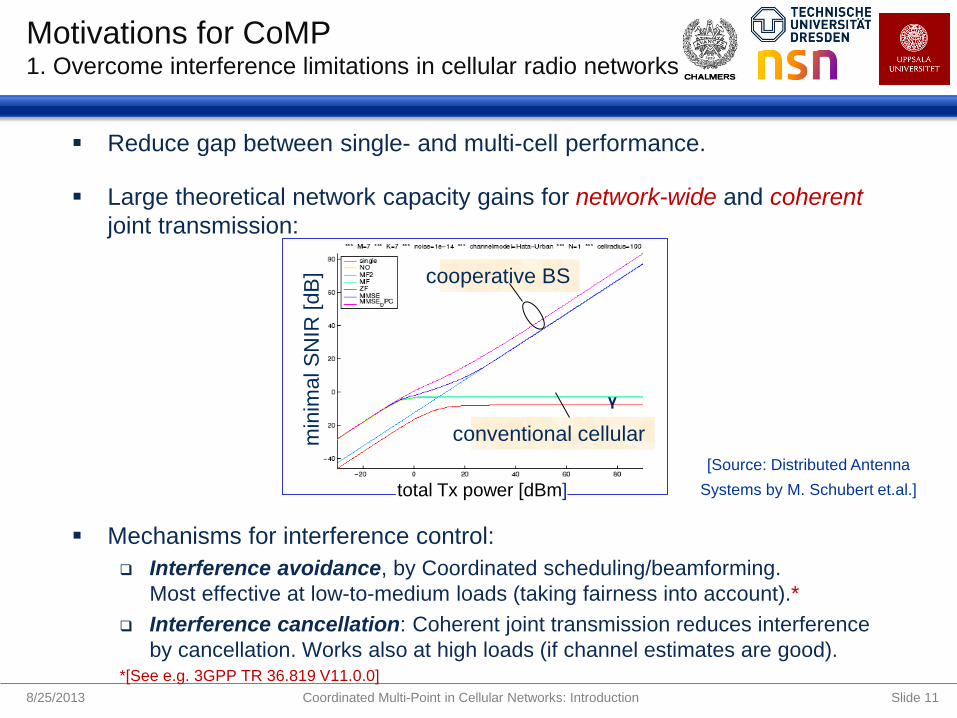
Reduce gap between single- and multi-cell performance.
Large theoretical network capacity gains for network-wide and coherent
joint transmission:
Mechanisms for interference control:
Interference avoidance, by Coordinated scheduling/beamforming.
Most effective at low-to-medium loads (taking fairness into account).*
Interference cancellation: Coherent joint transmission reduces interference
by cancellation. Works also at high loads (if channel estimates are good). *[See e.g. 3GPP TR 36.819 V11.0.0]
8/25/2013 Slide 11
Motivations for CoMP 1. Overcome interference limitations in cellular radio networks
conventional cellular
cooperative BS
min
imal S
NIR
[dB
]
γ
[Source: Distributed Antenna
Systems by M. Schubert et.al.]
Coordinated Multi-Point in Cellular Networks: Introduction
total Tx power [dBm]
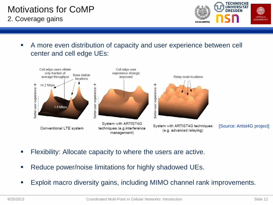
A more even distribution of capacity and user experience between cell
center and cell edge UEs:
Flexibility: Allocate capacity to where the users are active.
Reduce power/noise limitations for highly shadowed UEs.
Exploit macro diversity gains, including MIMO channel rank improvements.
8/25/2013 Slide 12
Motivations for CoMP 2. Coverage gains
[Source: Artist4G project]
Coordinated Multi-Point in Cellular Networks: Introduction

Cooperative transmission over several cells and sites using already
deployed antennas and RF front-ends.
Enable multi-user MIMO transmission/reception (network MIMO)
with cooperating (distributed) antennas at the network side.
But…
This requires adequate communication/coordination links and
intelligence within the cooperation areas.
Antennas/BSs will have different distances to a user. Can they then
still cooperate efficiently? If not always, then under what conditions?
(Cancelling weak interference components can provide significant SINR gains.)
8/25/2013 Slide 13
Motivations for CoMP 3. Efficient use of existing infrastructure
Coordinated Multi-Point in Cellular Networks: Introduction
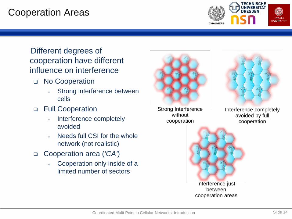
Different degrees of
cooperation have different
influence on interference
No Cooperation
Strong interference between
cells
Full Cooperation
Interference completely
avoided
Needs full CSI for the whole
network (not realistic)
Cooperation area ('CA')
Cooperation only inside of a
limited number of sectors
Interference just between
cooperation areas
Interference completely avoided by full
cooperation
Strong Interference without
cooperation
Cooperation Areas
Coordinated Multi-Point in Cellular Networks: Introduction Slide 14
conventional cellular
cooperative BS
min
ima
l S
NIR
[d
B]
γ
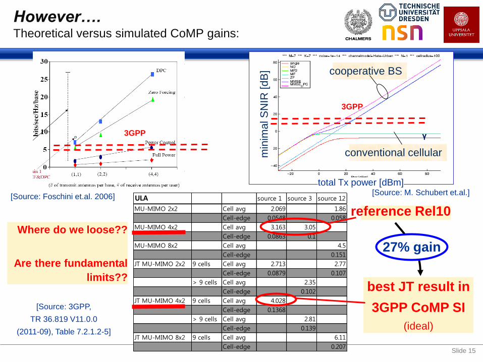
ULA source 1 source 3 source 12
MU-MIMO 2x2 Cell avg 2.069 1.86
Cell-edge 0.0548 0.058
MU-MIMO 4x2 Cell avg 3.163 3.05
Cell-edge 0.0863 0.1
MU-MIMO 8x2 Cell avg 4.5
Cell-edge 0.151
JT MU-MIMO 2x2 9 cells Cell avg 2.713 2.77
Cell-edge 0.0879 0.107
> 9 cells Cell avg 2.35
Cell-edge 0.102
JT MU-MIMO 4x2 9 cells Cell avg 4.028
Cell-edge 0.1368
> 9 cells Cell avg 2.81
Cell-edge 0.139
JT MU-MIMO 8x2 9 cells Cell avg 6.11
Cell-edge 0.207
However…. Theoretical versus simulated CoMP gains:
reference Rel10
best JT result in
3GPP CoMP SI
(ideal)
27% gain
Where do we loose??
Are there fundamental
limits??
total Tx power [dBm]
3GPP
[Source: Foschini et.al. 2006]
3GPP
[Source: M. Schubert et.al.]
[Source: 3GPP,
TR 36.819 V11.0.0
(2011-09), Table 7.2.1.2-5]
Slide 15

A preview of where we are heading:
1. Cooperation areas have to be designed carefully
to provide gains for most users.
2. Interference from outside the CA needs to be reduced
so that it does not swamp the intra-CA gains.
3. Groups of users that cooperate in a resource block
need to be selected well, but still fast and efficiently.
8/25/2013 Slide 16
How to attain more of the theoretical gains?
Coordinated Multi-Point in Cellular Networks: Introduction

A preview of where we are heading:
1. Cooperation areas have to be designed carefully
to provide gains for most users.
2. Interference from outside the CA needs to be reduced
so that it does not swamp the intra-CA gains.
3. Groups of users that cooperate in a resource block
need to be selected well, but still fast and efficiently.
Additional important aspects and practical constraints:
Channel estimation/prediction accuracy
Channel reporting feedback: accuracy and load in FDD
Transmit power constraints
Control signalling load, data distribution load limits
Time synchronization limitations to/from multiple sites.
(All these issues e.g. limit the practical cooperation area size.)
8/25/2013 Slide 17
How to attain more of the theoretical gains?
Coordinated Multi-Point in Cellular Networks: Introduction

Main aspects/techniques in focus in this Tutorial:
System design aspects, inter-relationships that affect the performance
Joint transmission/detection (for performance reasons)
Centralized coordination (for performance reasons)
Linear, mainly coherent, precoding (complexity and performance).
Outline:
Theory and Practice: MIMO, Network MIMO and LTE status
Key challenges and enablers for downlink joint transmission
A harmonized downlink framework: Outcomes of the EU Artist4G Project
Uplink aspects and Joint Detection
8/25/2013 Slide 18
Coordinated Multi-Point in Cellular Networks From Theoretical Gains to Realistic Solutions and Their Potentials
Coordinated Multi-Point in Cellular Networks: Introduction

THEORY AND PRACTICE
8/25/2013 Coordinated Multi-Point in Cellular Networks Slide 19

Section Overview
Precoding and equalization
Multi-user MIMO systems
Network MIMO systems
Toy scenario results
Practical impairments
3GPP results
8/25/2013 Slide 20 Coordinated Multi-Point in Cellular Networks: Theory and Practice

From MIMO to Network MIMO MIMO Precoding and Equalization
singular value decomposition (SVD) and parallel channels
A matrix can be decomposed such that
8/25/2013 Slide 23
Linear spatial precoding and equalization parallelizes the channel into its Eigenmodes
This opens the door for power control (waterfilling) to maximize capacity
use all modes in case of high SNR
one or few strongest modes in case of low SNR
optimal because Shannon formula is concave in the power
Precoding requires transmitter CSI
TX RX
Coordinated Multi-Point in Cellular Networks: Theory and Practice

MIMO multiple access system, Uplink:
From MIMO to Network MIMO Multi-User MIMO
8/25/2013 Slide 25
UEs might transmit one or several data streams
Spatial equalization (decorrelation) done at the BS
Links of UEs experience different pathloss & large scale fading that
might be compensated by power control
Timing of received signals at BS can be aligned using timing advance
1 2
K
UE
BS Eq
ua
liza
tion
demapping
demodulation
decoding
UE1
UE2
UEK
Coordinated Multi-Point in Cellular Networks: Theory and Practice

Multi-user MIMO (broadcast channel), Downlink:
CSI at transmitter required to separate Tx streams at receivers
Dirty paper coding is capacity achieving
Linear precoding techniques (e.g. ZF for channel inversion at the transmitter)
allow min(Nbs,NUE) increase of data rate at high SNR
Potentially, combination of precoding and equalization if UEs are equipped
with several receive antennas
From MIMO to Network MIMO Multi-User MIMO
8/25/2013 Slide 26
BS Pre
co
din
g
coding
modulation
mapping
UE1
UE2
UEK
Coordinated Multi-Point in Cellular Networks: Theory and Practice

From MIMO to Network MIMO network MIMO
Slide 27
Consider a cellular system with frequency
reuse one
High performance when users located in
vicinity of assigned base stations
Interference problem when users are located
at cell edges
In general: Cellular communications
systems with independent base stations are
interference limited -> low SINR at cell edges
network MIMO to
Jointly transmit/detect
Mitigate interference
Increase spectral efficiency
Coordinated Multi-Point in Cellular Networks: Theory and Practice
Base station time (and frequency) synchronization of base stations is required
Received symbol timing cannot be aligned due to propagation delays on
different paths
However

From MIMO to Network MIMO network MIMO
8/25/2013 Slide 28
1 2
cell edge
Coordinated Multi-Point in Cellular Networks: Theory and Practice
pathloss exponent = 3.5
omnidirectional antennas
dsite = 2000 m
cell-edge SNR = 18 dB
Nue = 2, Nbs = 2
Uncorrelated Rayleigh fading
no shadow fading
ML receiver
Potentially larger gains in cellular systems
due to shadowing
due to universal frequency reuse

From MIMO to Network MIMO network MIMO
8/25/2013 Slide 29 Coordinated Multi-Point in Cellular Networks: Theory and Practice
pathloss exponent = 3.8
coordination in user centric clusters of 19 cells
no outer cluster interference
dsite = 500 m
cell-edge SNR = 18 dB (strong interference
limitation)
Uncorrelated Rayleigh fading
shadow fading included
perfect transmitter CSI
[Source: Foschini et.al. 2006]
[Source: Foschini et.al. 2006]

Current Status in 3GPP CoMP Scenarios used for evaluation
8/25/2013 Slide 35 Coordinated Multi-Point in Cellular Networks: Theory and Practice
[Source: Lee et.al. 2012]
Homogeneous as well as
heterogeneous scenarios with
macro cells and low power
nodes
1) intra site CoMP 2) homogeneous inter site CoMP
3) heterogeneous setup
independ cell ID
4) heterogeneous setup same
cell ID

ULA source 1 source 3 source 12
MU-MIMO 2x2 Cell avg 2.069 1.86
Cell-edge 0.0548 0.058
MU-MIMO 4x2 Cell avg 3.163 3.05
Cell-edge 0.0863 0.1
MU-MIMO 8x2 Cell avg 4.5
Cell-edge 0.151
JT MU-MIMO 2x2 9 cells Cell avg 2.713 2.77
Cell-edge 0.0879 0.107
> 9 cells Cell avg 2.35
Cell-edge 0.102
JT MU-MIMO 4x2 9 cells Cell avg 4.028
Cell-edge 0.1368
> 9 cells Cell avg 2.81
Cell-edge 0.139
JT MU-MIMO 8x2 9 cells Cell avg 6.11
Cell-edge 0.207
Current Status in 3GPP 3GPP simulated CoMP gains
reference Rel10
best JT result in
3GPP CoMP SI
(ideal)
27% gain
[Source: 3GPP,
TR 36.819 V11.0.0
(2011-09), Table 7.2.1.2-5]

Current Status in 3GPP
Up to 8 transmit antennas in the downlink
Differences between theory and 3GPP:
Rayleigh channel models in theory, SCM in 3GPP
Evaluations with perfect channel estimation also in 3GPP
Network wide (theory) vs. clustered (3GPP) precoding
Outdoor to indoor penetration loss in 3GPP leads to noise limitation.
Tools for interference measurements in Release 11
No specific support for joint transmission CoMP in Release 11
Improved feedback would need to be standardized
No new Reference symbols
Specification for MIMO can potentially be used for CoMP as well
CSI reference symbols defined in Release 10 probably adequate
Channel feedback
Uplink joint detection can potentially be implemented without
changes on the air interface.
8/25/2013 Slide 37 Coordinated Multi-Point in Cellular Networks: Theory and Practice

Theory and Practice Main messages of Section
What we learned from theory
Linear MIMO gain requires high S(I)NR and uncorrelated channel
realizations.
Cell edge SINR in a non-cooperative cellular system is very low
due to inter-cell interference or penetration loss for indoor users.
Joint signal processing (network MIMO) can be used to exploit
inter-cell propagation.
Large gains of joint signal processing in toy scenarios and
simplified system level simulations with network wide cooperation.
What we see in practical implementations
Additional practical impairments.
3GPP system level simulation results show small network MIMO
gains.
8/25/2013 Coordinated Multi-Point in Cellular Networks: Theory and Practice Slide 38

EVALUATION OF KEY
CHALLENGES AND ENABLERS
FOR DOWNLINK JOINT
TRANSMISSION
8/25/2013 Coordinated Multi-Point in Cellular Networks Slide 39

Downlink JT Key Challenges and Enablers Signal Processing and System Design
Transmitter CSI
Channel estimation, accuracy requirements
CSI feedback: Outdating, overhead and quantization
Channel prediction
Zero-forcing linear precoding
Use of accuracy estimates in robust linear precoders
Complexity of network wide cooperation
Clustering: Cooperation areas
Inter-cluster interference floor, complexity of cooperation
Backhaul aspects (topologies, technologies, capacity, latency)
Time and frequency synchronization of base stations
8/25/2013 Slide 40 Coordinated Multi-Point in Cellular Networks: Challenges and Enablers

Coordinated beamforming requires information on ”forbidden”
directions /signal subspaces for interference avoidance.
Coherent joint transmission furthermore requires
accurate channel phase estimates for interference cancellation.
Signal subtraction (interference cancellation) is sensitive:
Channel estimates from several base stations in cooperation area:
Adequate estimation quality for the weakest channels?
Orthogonal reference signals within CA: density/overhead tradeoff.
FDD Downlinks: Uplink reporting load for channel estimates.
Non-static users, transmission feedback delay + CoMP delays
=> Channel outdating. Problems already at pedestrian velocity.
=> Need for channel prediction, based on most recent estimates.
Residual phase rotation of channels (synchronization inacuracies,
phase noise) can be tracked by channel predictors.
8/25/2013 Slide 41
CSI: Special Needs for Downlink CoMP Channel estimation and prediction
Coordinated Multi-Point in Cellular Networks: Challenges and Enablers

CSI: Channel Estimation, LTE Rel 10 CSI RSs - including interference floor shaping. Ref. signal SIR statistics
1
2
3
4
5
6
7
8
9
1..4
5..8
9..1
2 13..16
17..20
20..24
25..28
29..32
33..36
1
2
3
4
5
6
7
8
9
1..4
5..8
9..1
2 13..16
17..20
20..24
25..28
29..32
33..36
1
2
3
4
5
6
7
8
9
1..4
5..8
9..1
2 13..16
17..20
20..24
25..28
29..32
33..36
1
2
3
4
5
6
7
8
9
1..4
5..8
9..1
2 13..16
17..20
20..24
25..28
29..32
33..36
1
2
3
4
5
6
7
8
9
1..4
5..8
9..1
2 13..16
17..20
20..24
25..28
29..32
33..36
1
2
3
4
5
6
7
8
9
1..4
5..8
9..1
2 13..16
17..20
20..24
25..28
29..32
33..36
1
2
3
4
5
6
7
8
9
1..4
5..8
9..1
2 13..16
17..20
20..24
25..28
29..32
33..36
1
2
3
4
5
6
7
8
9
1..4
5..8
9..1
2 13..16
17..20
20..24
25..28
29..32
33..36
1
2
3
4
5
6
7
8
9
1..4
5..8
9..1
2 13..16
17..20
20..24
25..28
29..32
33..36
subset of orthogonal CSI RSs
muting patterns:
simultaneously active sites
have same colour
large minimum distance between
simultaneously active CSI RSs Coordinated Multi-Point in Cellular Networks: Challenges and Enablers Slide 42
LTE Rel.10 CSI RS: 40RE
SIR [dB] 0 60 40 20 -20

FDD systems:
Outdating: Feedback +proc.delay(5 ms) +2 x Backhaul latency(1-20ms).
Problematic at pedestrian velocities at > 2.0 GHz carriers.
Uplink overhead: A few Mbit/s over
a 10-20 MHz uplink*
(complex numbers or gain + phase).
TDD systems:
Using uplink estimates for downlink:
Outdating: 2 x Backhaul latency.
Overhead: Uplink pilots from all users, in all utilized RBs, detected in all cells.
Out-of CA-interference is not reciprocal. May need uplink feedback as in FDD.
Quantization:
8 bits per complex channel results in small linear precoder performance loss.
Should also report CSI reliability!
8/25/2013 Slide 43
CSI Feedback Outdating, overhead and quantization for Centralized joint transmission
Coordinated Multi-Point in Cellular Networks: Introduction
*[EU FP7 Artist4G Project Deliverable D1.4, Section 5.3.3. https://ict-artist4g.eu/ ]

8/25/2013 Slide 44
CSI: Channel Prediction Performance using Kalman prediction (optimal linear MMSE prediction)
Example: Predicting 4 channels for
• Different Doppler spectra
• Ref. signal SIR = 6 ,12 & 18 dB.
e.g. prediction NMSE -10 dB (indicated) is
attainable for 0.1- 0.3 wavelength horizon,
or 8 ms – 24 ms at 5 km/h at 2.66 GHz.
Attainable dB cancellation by coherent
JT CoMP = Normalized Mean Square
Error (NMSE) of channel estimates.
[See Daniel Aronsson, Channel Estimation and Prediction for MIMO OFDM Systems: Key design aspects of
Kalman-based algorithms. PhD Thesis, Signals and Systems, Uppsala University, March 2011, Chapter 6.5.]
6 dB
12 dB
18 dB
Frequency selective
Flat fading
Flat Doppler spectrum:
(Hard to predict)
Jakes (Rayleigh fading)
Doppler spectrum:
Residual phase rotation
due to synch. error with jitter
Coordinated Multi-Point in Cellular Networks: Challenges and Enablers

CSI: Zero-Forcing (ZF) Linear Precoder using estimated/predicted channels from transmitters in CA
Downlink channels within OFDM resource block: Complex matrix H.
Pre-inversion by zero forcing precoder W when estimate is invertible:
When # transmitters > # receiver antennas within cooperation area:
Regularized pre-inversion or Moore-Penrose pseudoinverse:
The precompensated channel matrix is ideally
The „target matrix“ is (block)diagonal and contains per-stream gains.
These gains can be optimized to maximize e.g. a weighted sum rate,
under per transmit antenna power constraints.
Large eigenvalue spread of channel matrix leads to precoders that have small
gains for nearest BS => Still interference cancellation, but bad SNR.
Power normalization loss problem.
8/25/2013 Slide 45 Coordinated Multi-Point in Cellular Networks: Challenges and Enablers
DHW1
ˆ
DHHHW *1
* ˆˆˆ
H
DHHHW1
** ˆˆˆ
DHW
D

8/25/2013 Slide 46
CSI: Robust Linear Precoder Taking channel accuracy (covariance) information into account
Coordinated Multi-Point in Cellular Networks: Challenges and Enablers
Kalman predictors provide prediction uncertainty Ē{ΔH*ΔH}.
CoMP precoder should be designed by taking all relevant information into account.
We may use a scalar criterion:
The precoder minimizing J is then:*
Weights V and S can be adjusted iteratively to optimize SINR, local capacity, utility…**
22)()( tSuEtVEEJ
VDVHHVVHESSHVVHR **1
***** ˆˆˆ
d(t) Transmit symbols for M users
u(t) Transmit signal, N transmitters.
y(t) Received signal excl. noise
z(t) Target signals at receivers
ε(t) Error signal (M-vector)
R Precoding matrix (N x M)
H Channel matrix (M x N)
Hpred Predicted channel matrix
ΔH Prediction error matrix, E(ΔH)=0
D Target system (M x M), diagonal
S Transmit power penalty matrix
(N x N), usually diagonal, ≥ 0
V Error penalty matrix (M x M),>0
c Scalar transmit scaling factor
* K. Öhrn, A. Ahlén and M. Sternad, ”A Probabilistic approach to multivariable robust filtering
and open-loop control”, IEEE Trans. on Autom. Contr, vol. 40, March 1995, pp. 405-417 .
** R. Apelfröjd, M. Sternad and D. Aronsson ”Measurement-based evaluation of robust linear
precoding in downlink CoMP”, IEEE ICC 2012, Ottawa .
Robust Linear Precoder
(block)diagonal Target matrix

CSI: Accuracy Requirements per CA - example ARTIST4G
IPpredictionPNLett
diag
diag
pinv
pinv
CSICSI)(CSICSICSICSI
-
max
H
))Y-Y(
)YSIR ;WHY
WWW
HW
HW
HHH
W arg
ˆ(ˆ
ˆ(ˆˆ
ˆ
)ˆ(ˆ
)(
ˆ
4 WB beams per cell
full cooperation
3 active UEs / cell
Channel quantization and prediction
errors cause violation of
multi-user orthogonality!
-20dB 0..-20dB -1..-5dB xxxdB <-26…40dB! +1..xdB
system design
+
fine tuning
depends on
quantization
+
# of relevant CCs
depends on
prediction range
+
UE mobility
+
channel variations
interpolation gain
# of RSs, PRS,f+t-variation
1
2
3
4
5
6
7
8
9
Coordinated Multi-Point in Cellular Networks: Challenges and Enablers Slide 47

eNB broadcasts BVDM and CSI RSs
UE Positioning within BVDM (GPS localization + channel matching)
Feedback of UE 3D Position + moving vector + CSI
eNB: reconstruction of DL CSI within BVDM
predict CSI evolution based on moving vector vm
Massive MIMO and JT CoMP: CSI accuracy is the main limitation
SoA: Wiener or Kalman filtering prediction to about 0.1 - 0.3
Approach: combine SoA with model based channel prediction.
UE1
UE1 GPS based location: 1m accuracy
moving vector vm: speed + direction
BVDM at eNB
BVDM at UE
e.g. broadcasted from eNB
BVDM: Building Vector Data Map
extreme FB compression!!??
CSI: Long-term Vision - Model Based Channel Prediction
Coordinated Multi-Point in Cellular Networks: Challenges and Enablers Slide 48

Different degrees of
cooperation have different
influence on interference
No Cooperation
Strong interference between
cells
Full Cooperation
Interference completely
avoided
Needs full CSI for the whole
network (not realistic)
Cooperation area ('CA')
Cooperation only inside of a
limited number of sectors
Inter-CA interference limits
gains, even for large CAs! Interference just
between cooperation areas
Interference completely avoided by full
cooperation
Strong Interference without
cooperation
Complexity of Network-wide Cooperation Cooperation Areas
Coordinated Multi-Point in Cellular Networks: Introduction Slide 49

Complexity of Network-wide Cooperation Inter-cluster interference floor vs CA size
Performance asymptotically increasing with cluster size
Inter-cooperation area interference is a serious limitation.
8/25/2013 Slide 50 Coordinated Multi-Point in Cellular Networks: Challenges and Enablers
[Source: Lars Thiele et.al., Chapter 6.3 in P.March ed. Coordinated Multipoint in Mobile Communications, 2011]

Backhaul Media and Architecture
8/25/2013 Slide 51 Coordinated Multi-Point in Cellular Networks: Challenges and Enablers

Backhaul Protocols and Topologies
8/25/2013 Slide 52 Coordinated Multi-Point in Cellular Networks: Challenges and Enablers
Star Chain Tree Ring
Source: R. Chundury ”Mobile broadband
backhaul: Addressing the challenge”,
Ericsson Review No. 3, 2008. © Ericsson
AB 2013- All Rights Reserved.

Backhaul Networks
=> Heterogenous Backhaul networks
=> Inter-BS connections with heterogeneous connectivity, capacity and latency.
8/25/2013 Slide 53 Coordinated Multi-Point in Cellular Networks: Challenges and Enablers
Source: A. Bolle, A. Nascimbene
”Microwave transmission in mobile
networks”, Ericsson Review No. 3,
2002. © Ericsson AB 2013- All Rights
Reserved.

Synchronization Issues
Time- and frequency synchronization btw eNBs:
is essential basic enabler
In 3GPP sometimes argument against JT CoMP
Requirements [ LTE: SC spacing 15kHz, SF length 1ms, GI: 4.7s, FB delay 10ms ]:
Time: within fraction of an OFDM guard interval (< one to very few s)
Frequency: ideally below 0.1ppb at RF of 2.6GHz
Phase Noise (>100Hz): can’t be compensated requires high Q LOs
Options for frequency synchronization:
GPS + tight synchronization with extremely stable TXOs (see demo systems)
IEEE 1588v2 - precision time protocol (PTP): avoids GPS, accuracy unclear
over the air synchronization: based on UE feedback (single value per eNB!)
CSI reporting with channel prediction
e.g. based on simple linear prediction
OFDM symbol
eNB1
eNB 2
GI should cover: tsync + delay spread + 1-2
Coordinated Multi-Point in Cellular Networks: Challenges and Enablers Slide 54

Frequency Synchronization
A) Inter carrier interference: neglectable for typical f of about 100Hz
0 50 100 150 200 250 300 350 400 450-0.4
-0.2
0
0.2
0.4
0.6
0.8
1
Inter carrier interference for f=500Hz
LTE: f=<100Hz
SIR >20dB
A) Inter carrier interference
[K. Manioakis, V. Jungnickel, “Synchronization requirements for OFDM-based cellular networks with coordinated base stations: Preliminary results“]
0.5 ppb
2 ppb
5 ppb
0.007 ppb
0.03 ppb
0.1 ppb
= 70s
= 7ms
(, f)
B) inter eNB phase drift:
= 10ms and f= 100Hz (10ms) = 0.01*100Hz= 360° !!!
tight synchronization or (linear) CSI prediction !
0.1 ppb (7ms) = 0.007*0.26Hz= 0.6° !!!
Coordinated Multi-Point in Cellular Networks: Challenges and Enablers Slide 55

Frequency Offset Estimation + Feedback
0 10 20 30 40 50 600
10
20
30
40
50
60
time [ms]
delta p
hi [r
ad]
Phase evolution with (b) and without (r) delta f
phase evolution of radio channel
UE speed = 10m/s
f = 112Hz
Ray tracing simulation including birth and
death of multi path components
red: mean phase evolution, f= 0Hz
blue: mean phase evolution, f= 112Hz
magenta: est. phase rotation
black: phase rotation for f= 112Hz
linear f estimation few Hz estimation error
advanced estimation < 1Hz possible
SINR=20dB
advanced detect phase jumps
f= 0Hz
f= 112Hz
Coordinated Multi-Point in Cellular Networks: Challenges and Enablers Slide 56

ARTIST4G HARMONIZED
FRAMEWORK
8/25/2013 Coordinated Multi-Point in Cellular Networks Slide 57

Goal: To Increase Attainable CoMP Gains Signal Processing and System Design
Creative engineering thinking
What are the potential game changers?
In which research directions should we go?
System level concept: Some pieces of the puzzle:
clustering
interference floor shaping
user grouping, (robust) precoding, scheduling and resource allocation
what is the optimum based on interference function?
optimal linear beamforming (including power constraints)
relationships between user grouping and linear/non-linear precoding
effects of resource allocation, loading and DoF
recognize practical limitations and implementation constraints
receiver capabilites
use of interference rejection combining
8/25/2013 Slide 58 Coordinated Multi-Point in Cellular Networks: Artist4G Harmonized Framework

Main Investigated Scenario
Target scenario close to 3GPP case 1:
homogeneous macro cellular network with19 sites and overall 57 (128) cells
8/25/2013 Slide 59
Number of eNBs: 57
Number of sites: 19
Cells per site: 3
Sector width: 120 deg
Height of UEs / eNBs: 1.6 / 25m
Number of PRBs: 32
Bandwidth per PRB: 180 kHz
TxAEs, RxAEs: 4 x 2
Antenna configurations: ULA, /2 spacing
Algorithm for JP: ZF or robust JT
Channel modell: SCME
ISD: 500m
CSI: Ideal
Number of UEs per cell: 10
Interference limited macro scenario
4 static wideband
beams per cell
no flashlight effect
small loss compared to free TX beamformers
1
2
3
4
5
6
7
8
9
Coordinated Multi-Point in Cellular Networks: Artist4G Harmonized Framework
Clustering
8/25/2013 Slide 60 Coordinated Multi-Point in Cellular Networks: Artist4G Harmonized Framework

Clustering: Enlarged Cooperation Areas
User-centric clustering would be ideal.
Problem with User-centric clustering :
very low number of UEs wish same set of cells
low penetration rate and / or low CoMP gain
even w extensive optimization unsolvable!!
Solution Step 1): Use static, but enlarged, cooperation areas
3 sites a’ 3 cells leads to CAs of 9 cells
practical approach with limited number of backhaul links
high number of UEs having 3 strongest cells in one 9-cell-CA
Coordinated Multi-Point in Cellular Networks: Artist4G Harmonized Framework Slide 61

With six cover shifts all UEs having their 3
strongest cells within 3 adjacent sites are
being served user centric
cover shift 1
cover shift 2
Clustering: Cover Shifts
Solution Step 2): Cover Shifts
Cover shifts are orthogonal resources like frequency subbands or
time slots used for overlapping setup of cooperation areas
eNBs schedule UEs into one or more best fitting cover shift(s)
e.g. 90% of UEs served user centric (3 strongest cells within CA)
Note: this remains a frequency reuse 1 system!
Coordinated Multi-Point in Cellular Networks: Artist4G Harmonized Framework Slide 62
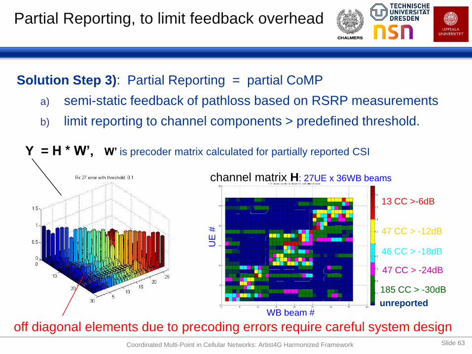
Partial Reporting, to limit feedback overhead
Solution Step 3): Partial Reporting = partial CoMP
a) semi-static feedback of pathloss based on RSRP measurements
b) limit reporting to channel components > predefined threshold.
13 CC >-6dB
47 CC > -12dB
46 CC > -18dB
47 CC > -24dB
185 CC > -30dB
channel matrix H: 27UE x 36WB beams
Y = H * W’, W’ is precoder matrix calculated for partially reported CSI
off diagonal elements due to precoding errors require careful system design
unreported WB beam #
UE
#
Coordinated Multi-Point in Cellular Networks: Artist4G Harmonized Framework Slide 63
Interference Floor Shaping
8/25/2013 Slide 64 Coordinated Multi-Point in Cellular Networks: Artist4G Harmonized Framework

Rate Regions versus Interference Floor
R2
R1 noise floor:
low for IF limited scenarios
max MCS R2max
max MCS R1max
optimum rate region for CoMP
rate region
w IF floor
Significant loss due to IF floor &
small gain over non CoMP case
rate region
w/o CoMP
Coordinated Multi-Point in Cellular Networks: Artist4G Harmonized Framework Slide 65

Tortoise like shape of
Rx power over location
15° tilt
40dBm
7° tilt / 46dBm
Interference Floor Shaping: ‘Tortoise’ Concept
Tortoise Concept:
Generate tortoise like power distribution per CA by
cell specific antenna tiltings:
CA center/outbound wideband beams
with low/strong tilt & strong/low Tx power
Per cover shift, serve mainly CA-centric UEs
(CA edge UEs are scheduled into other best fitting
cover shift.)
Goal: Reduce inter-CA interference
Benefits:
Approaching network wide cooperation gains
Robust and simple solution (e.g. use active antennas)
Decoupling of CAs optimization per CA possible.
Coordinated Multi-Point in Cellular Networks: Artist4G Harmonized Framework Slide 66
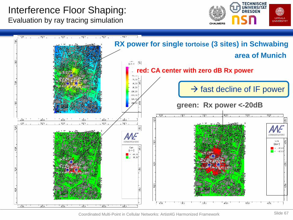
RX power for single tortoise (3 sites) in Schwabing
area of Munich
red: CA center with zero dB Rx power
green: Rx power <-20dB
fast decline of IF power
Interference Floor Shaping: Evaluation by ray tracing simulation
Coordinated Multi-Point in Cellular Networks: Artist4G Harmonized Framework Slide 67

Interference Floor Shaping: TUD real world measurements of tortoise concept
TUD testbed: pathloss measurements for 27 cells
realistic serving and interfering cells
close to intended ideal ‚tortoise‘ shape
single tortoise Rx power
Coordinated Multi-Point in Cellular Networks: Artist4G Harmonized Framework Slide 68
[Mennerich et. al]

WP1 /25
Effect of antenna tilting similar to modeled and
close to ray tracing investigations.
Coordinated Multi-Point in Cellular Networks: Artist4G Harmonized Framework
Interference Floor Shaping: TUD real world measurements of Tortoise concept
Slide 69

Two Stage Scheduler
8/25/2013 Slide 70 Coordinated Multi-Point in Cellular Networks: Artist4G Harmonized Framework

Radio Channel Conditions Within a CA Power differences and (large) Singular value spread
The radio channel conditions: (SCME case 1)
define the upper performance bound
are very important for a proper system design
Relevant parameters are e.g. correlations, power distributions, etc.
8/25/2013 Slide 71
5
10
15
20
25
30
10
20
30
40
50
60
70
-120
-110
-100
SC
Rx power compared to noise floor for Noise figure 7dB noise figure
8 beams * 9 eNB
Rx P
ow
er
in d
B
Rx power
[dB]
PRB #
9 cells x 8 AEs
0 5 10 15 20 25 30 35-100
-80
-60
-40
-20
0
20Eigenvalues in [dB] for 4 Tx eNBs and 1 Rx UE; Tx power adapted
Singular values for randomly chosen UEs
SV
[dB]
# of UEs
SL simulation w
1 UE per cell
1 cell with 3 UEs
indicates strong inter WB
beam correlation in cells
WB beam correlation per cell
power variation due to antenna tilt
inter cell rank
enhancement
low
power cells
Coordinated Multi-Point in Cellular Networks: Artist4G Harmonized Framework
=> Coherent JT CoMP problematic for random user locations
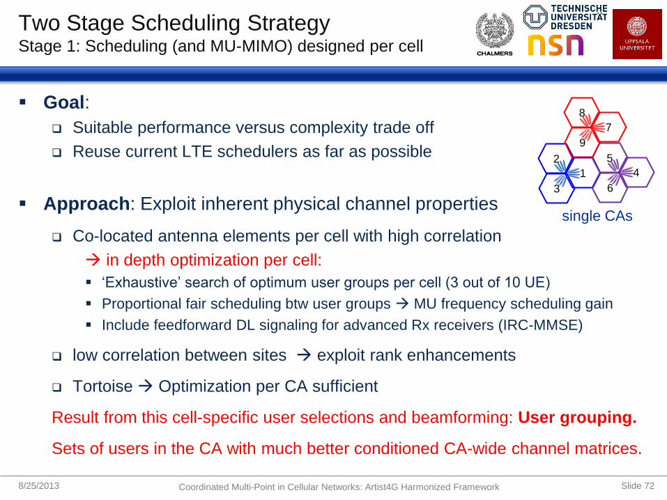
Two Stage Scheduling Strategy Stage 1: Scheduling (and MU-MIMO) designed per cell
Goal:
Suitable performance versus complexity trade off
Reuse current LTE schedulers as far as possible
Approach: Exploit inherent physical channel properties
Co-located antenna elements per cell with high correlation
in depth optimization per cell:
‘Exhaustive’ search of optimum user groups per cell (3 out of 10 UE)
Proportional fair scheduling btw user groups MU frequency scheduling gain
Include feedforward DL signaling for advanced Rx receivers (IRC-MMSE)
low correlation between sites exploit rank enhancements
Tortoise Optimization per CA sufficient
Result from this cell-specific user selections and beamforming: User grouping.
Sets of users in the CA with much better conditioned CA-wide channel matrices.
8/25/2013 Slide 72
1
2
3
4
5
6
7
8
9
single CAs
Coordinated Multi-Point in Cellular Networks: Artist4G Harmonized Framework
-
Cell 3
scheduler Cell 2
scheduler Cell1
scheduler
Cell M
scheduler
NBS=4
Cooperation area CAb
scheduler
NUE=2
K=10 UEs per celll
site s1 site s2
site s3
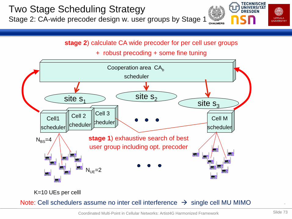
Two Stage Scheduling Strategy Stage 2: CA-wide precoder design w. user groups by Stage 1
stage 1) exhaustive search of best
user group including opt. precoder
stage 2) calculate CA wide precoder for per cell user groups
+ robust precoding + some fine tuning
Note: Cell schedulers assume no inter cell interference single cell MU MIMO
Coordinated Multi-Point in Cellular Networks: Artist4G Harmonized Framework Slide 73

WP1 /25
Relative Performance Gains (ideal CSI) Main evaluation case: 4 Tx, 2 Rx antennas, 3 site (9 cell) CAs
SINR [dB] Spectral
efficiency
bits/s/Hz/cell
SE gain [%] cell
edge average
Network wide CoMP (1) - - 8 / 15(2) 160
Network wide CoMP with
nonlinear precoding(1) - - 11 / 20 250
3GPP MU-MIMO - - 3.1 0 (reference)
3GPP JP-CoMP - - 4.0 30
9-cell CoMP (3) -2 12 - -
+ cover shift (3) 4 17 - -
+ IF floor shaping (3) 12 23 - -
+ 2-stage scheduler (4) 5 15 7.5 / 13 (2) 140
(1) Simulation conditions are not fully comparable; higher values are for nonlinear precoding
(2) Values after backslash ignore LTE overhead of 43%;
(3) SINR for single UE per cell and for 4x2;
(4) SINR for 2 to 3 out of 10 simultaneously scheduled UEs per cell and 4x2 configuration
Perfect transmitter CSI assumed in all evaluations above.
SINRs [dB] for single UE per cell
Coordinated Multi-Point in Cellular Networks: Artist4G Harmonized Framework Slide 74

Downlink JT CoMP Performance with
Imperfect CSI
8/25/2013 Slide 75 Coordinated Multi-Point in Cellular Networks: Artist4G Harmonized Framework

WP1 /25
Effects of Channel Estimation and SNR Main evaluation case: 4 Tx, 2 Rx antennas, 3 site (9 cell) CAs
Coordinated Multi-Point in Cellular Networks: Artist4G Harmonized Framework Slide 76
NF [dB) 0 10 15 25 20 -10 -15 -5 5
-15 -10 -5 0 5 10 15 20 25 300
1
2
3
4
5
6
7
8
NF in [dB]
SE
[b/s
/Hz/c
ell
]spectral efficiency over UE noise figure in [dB) with IPG=3 / 12 / 30 / 50 dB
SE
[b
/s/H
z/c
ell]
some fine tuning included
PL 20dB
UE NF 9dB
similar 3GPP
case 1 PL 0dB
UE NF 7dB
maximize
SNR ! enhance CSI
prediction !
Penetration Loss (PL)+ 3dB default UE Noise Figure (NF) in [dB]
IPG
0 dB
12 dB
30 dB
50 dB
PL: outdoor to indoor penetration loss; IPG: Interpolation Gain
Effects of SNR and Channel estimator interpolation gains (IPG) = – (SNR-NMSE) [dB].

Simultaneous Kalman prediction of single-antenna channels from three sites:
Measurements:
- Single-antenna transmitters
- 20 MHz OFDM channels
- 15 kHz subcarriers
- 2.66 GHz carrier
- Upsampled from 30 to 5 km/h
Channel prediction:
- Orthogonal ref. signals,
- Total RS overhead 1/9,
- Frequency-domain Kalman
based on AR4 fading models.
Average (over positions
and subcarriers)
prediction NMSEs,
at noise level -120 dBm:
8/25/2013 Slide 77
Performance Example. 1: Channel prediction Using channel sounding data from Stockholm (by Ericsson)
17.568 17.57 17.572
59.243
59.244
59.245
longitude
latitu
de
[EU FP7 Artist4G Project Deliverable D1.4, Appendix A4-2. https://ict-artist4g.eu/ ]
Prediction
horizon
(wavelengths)
In ms,
at
5km/h
NMSE, weakest
of 3 channels
(Kalman)
Average NMSE
for all channels
(Kalman)
[By using
outdated
CSI:]
0 0 ms - 12.7 dB - 23.9 dB - 23.9 dB
0.06 5 ms - 9.4 dB - 15.3 dB - 12.5 dB
0.13 10 ms - 7.4 dB - 12.9 dB - 7.9 dB
0.19 15 ms - 5.9 dB - 11.2 dB - 5.0 dB
0.28 23 ms - 4.1 dB - 9.2 dB - 2.1 dB
Coordinated Multi-Point in Cellular Networks: Artist4G Harmonized Framework
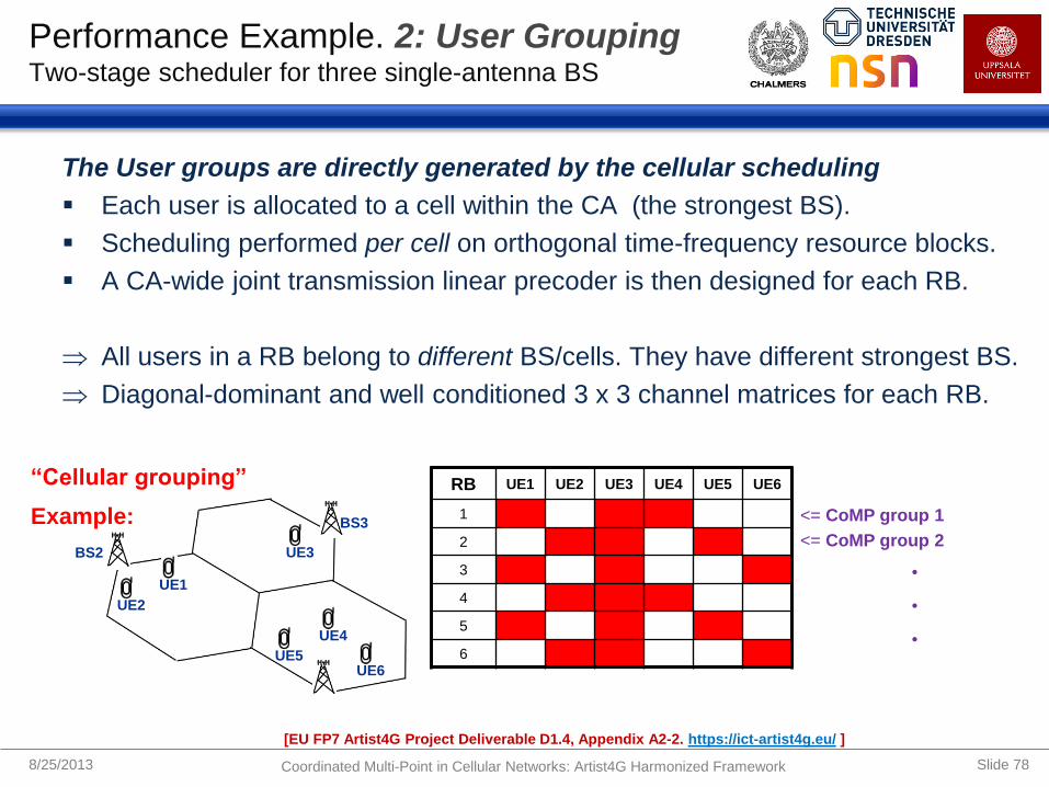
The User groups are directly generated by the cellular scheduling
Each user is allocated to a cell within the CA (the strongest BS).
Scheduling performed per cell on orthogonal time-frequency resource blocks.
A CA-wide joint transmission linear precoder is then designed for each RB.
All users in a RB belong to different BS/cells. They have different strongest BS.
Diagonal-dominant and well conditioned 3 x 3 channel matrices for each RB.
8/25/2013 Slide 78
Performance Example. 2: User Grouping Two-stage scheduler for three single-antenna BS
BS3
BS2 UE3
UE1
UE2
UE6
UE4
UE5
“Cellular grouping”
Example:
[EU FP7 Artist4G Project Deliverable D1.4, Appendix A2-2. https://ict-artist4g.eu/ ]
RB UE1 UE2 UE3 UE4 UE5 UE6
1
2
3
4
5
6
<= CoMP group 1
<= CoMP group 2
•
•
•
Coordinated Multi-Point in Cellular Networks: Artist4G Harmonized Framework

Measured channels for 1000 sets of 9 randomly placed users at (up to) 5 km/h.
Kalman predicted channels, 10 ms horizon, used for precoding. Average IPG -11dB.
User grouping (selecting 3 out of 9 users):
”Cellular grouping” as described above and random grouping.
Round Robin (RR) and Score-based (SB) opportunistic scheduling.
Interference: Similar to as when using ”Tortoise” scheme. Median SINR 24dB.
Zero forcing (ZF) linear precoding used below.
Comparing Sum Shannon rates [bit/s/Hz/cell] (without overhead):
ZF JT CoMP with random user grouping is not competitive with cellular.
55% improvement of average rates for CoMP with cellular grouping vs cellular.
8/25/2013 Slide 79
Performance Example. 3: Results CoMP vs reuse 1 cellular, for three single-antenna BS
Transmit scheme =>
Grouping and Sheduling:
CoMP
Average
CoMP
5% percentile
Cellular
Average
Cellular
5% percentile
Random grouping with RR 4.7 0.79 - -
”Cellular grouping” with RR 7.6 3.5 4.9 2.3
”Cellular grouping” with SB 8.5 4.8 5.5 3.5
[EU FP7 Artist4G Project Deliverable D1.4, Appendix A2-2, Table A.1 https://ict-artist4g.eu/ ]
Coordinated Multi-Point in Cellular Networks: Artist4G Harmonized Framework

1. Cooperation areas have to be designed carefully to provide gains for most users.
Use large (at least 3-site) and overlapping cooperation areas.
Almost all users are then in the center area of some CA in some cover shift.
2. Interference from outside the CA needs to be reduced.
Use combination of power control, frequency-specific downtilt or possibly
fractional frequency reuse.
3. User groups per resource block need to be selected well, but fast and efficiently.
Use two-stage scheduling and a linear CoMP precoder. Users are first
allocated frequency/spatial resources within cells. This reduces singular
value spreads and improves performance of linear CoMP precoders.
In addition:
Use partial reporting of channels to reduce feedback and estimation load.
We recommend the use of channel prediction, to improve performance and robustness.
We recommend the use of robust linear precoders, to better handle difficult cases.
8/25/2013 Slide 80
Artist4G Harmonized Downlink Framework Summary of main design principles, coherent joint transmission
Coordinated Multi-Point in Cellular Networks: Artist4G Harmonized Framework

ALTERNATIVE SOLUTIONS
AND OPEN ISSUES
8/25/2013 Coordinated Multi-Point in Cellular Networks Slide 81

Alternative Solutions Fractional frequency reuse for interference suppression
Inter-CA interference suppression efficient with power
control and large downtilt to the outside of CAs.
But this assumes frequency-dependent downtilts (per
Cover shift). May not be avaliable in present networks.
Simpler alternative: Use fractional frequency reuse
within cooperation areas:
8/25/2013 Slide 82 Coordinated Multi-Point in Cellular Networks: Alternative Solutions, Open Issues
7° tilt / 46dBm
15° tilt
40dBm

Licentiate Seminar Jingya Li
• A star-like network
• Coordinated BSs are connected to a control unit (CU) via backhaul links
• Total latency for an entire transmission loop, ∆tC = ∆F + 2∆B
h1
h2
h3
h2
h3
h1
1
2
3
h
H h
h
1
2
3
w
W w
w
w3
w1
w2
CU
Coordinated Multi-Point in Cellular Networks: Alternative Solutions, Open Issues
Baseline for Downlinks in Previous Section: Centralized processing coordination architecture
Central Unit (CU) per
cooperation area for
transmission control.
Data queues may be
centralized, or be
distributed to eNBs.
Slide 83

Licentiate Seminar Jingya Li
• A meshed network
• A CU is co-located at each BS
• Total latency for an entire transmission loop: ∆tSD = ∆F + ∆B
h1
h2
h3
h2 h3
h1
h3
h1
h2
3H
2H
1H
3w
2w
1w
Slide 84
Alternative Solution to Reduce Delays Semi-distributed processing
Coordinated Multi-Point in Cellular Networks: Alternative Solutions, Open Issues
CSI feedback unicast to one BS.
Distributed precoder calculation,
based on identical information.
Data queues distributed to eNBs.

Licentiate Seminar Jingya Li
h1
h2
h3 h3
h3
h2 h2
h1
h1
3H
2H
1H
3w
2w
1w
• A CU is co-located at each BS
• Each user broadcasts the CSI to all the BSs
• ∆tFD = ∆F, more sensitive to errors introduced via low-quality feedback channels
Slide 85 Coordinated Multi-Point in Cellular Networks: Alternative Solutions, Open Issues
CSI broadcast to several BSs in CA.
Distributed precoder calculation, based
on possibly different (and erroneous)
CSI feedback information.
Alternative Solution to Reduce Delays Fully distributed processing

Non-Coherent
Joint Transmission
Coordinated
Scheduling
Zero-Forcing
Joint Transmission
0.2 0.4 0.6 0.8 10
5
10
15
20
25
30
35
40
45
Avera
ge s
um
rate
[bps/H
z]
0.2 0.4 0.6 0.8 10
5
10
15
20
25
30
35
40
45
Normalized distance from serving BS0.2 0.4 0.6 0.8 10
5
10
15
20
25
30
35
40
45
Perfect CSI Centralized Semi-Distributed Distributed
Slide 86
Performance Example:
CoMP transmit schemes vs Coordination architectures
2.0 GHz,
3.0 km/h,
∆F = 5ms
∆B =10ms
Kalman
Prediction.
Coordinated Multi-Point in Cellular Networks: Alternative Solutions, Open Issues
Semi-Distributed:
15 ms delay.
Distributed: 5 ms
delay, but erroneous
feedback.

Slide 87
[Source for this and previous 4 slides: Licentiate Thesis presentation by Jingya Li, Chalmers, Feb.12 2013. See Li et. al. IEEE PIMRC 2012]
Performance Example:
CoMP Transmit schemes vs Speed
2.0 GHz,
Semi-
distributed,
∆F = 5ms
∆B =10ms
Kalman
Prediction.
Coordinated Multi-Point in Cellular Networks: Alternative Solutions, Open Issues

UPLINK ASPECTS AND JOINT
DETECTION
8/25/2013 Coordinated Multi-Point in Cellular Networks Slide 88

Uplink Aspect and Joint Detection Uplink Power Control
Less uplink power (Pmax = 23 dBm)
uplink power control in LTE
Goals: achieve fairness & minimize interference at other cells
single link (serving cell) closed loop/open loop power control
Parallel to partial CSI feedback (for downlink)
With joint detection, power control should take the links to all eNBs in the
cooperation cluster into account.
UE needs to know which eNBs actually cooperate
additional UE-eNB signaling required
UL CoMP can be implemented transparent to the UE which allows support of
legacy UEs
closed loop power component could be used to adjust UE transmit power
8/25/2013 Coordinated Multi-Point in Cellular Networks: Uplink Aspects and Joint Detection Slide 89

Uplink Aspect and Joint Detection Channel State Information
Channel information available without feedback delay
BSs measure the radio links and exchange the measurement reports to joint
detector (potentially a BS)
If the channel of uplink and downlink is reciprocal UL measurements could
be leveraged for adapting downlink transmissions
However, since interference is not reciprocal, UE feedback is always desirable to
obtain an estimate of the downlink interference experienced by a UE
If you want to do scheduling, you need the channels of many users.
interference floor shaping can be applied
Control Channels
In general uplink and downlink transmission need control channels, but some
control loops are only required in the uplink
– UL power control
– uplink timing advance
8/25/2013 Slide 90 Coordinated Multi-Point in Cellular Networks: Uplink Aspects and Joint Detection

Uplink Aspect and Joint Detection HARQ Issues
LTE HARQ protocol requires strict timing constraints
UL HARQ is based on synchronous re-transmissions
A negative HARQ achnowledgement (NACK) has to be transmitted
4ms after the initial transmission
cooperation (exchange of information over a backhaul) causes
additional delays
Delay depends mostly on the core/backhaul network topology and the
backhaul technology
Today, inter-eNB communication is not sensitive to communication
latency, i.e. latencies in the order of 10 ms are sufficient and occur.
Current technologies that support delays < 1 ms are
Ethernet (over fiber)
Microwave in E-Band (71 – 76 GHz, 81 – 86 GHz) provide up to 1
Gbits/s at about 100 µs delay
Passive optical networks XGPON
8/25/2013 Slide 91 Coordinated Multi-Point in Cellular Networks: Uplink Aspects and Joint Detection
Uplink Aspect and Joint Detection Backhaul
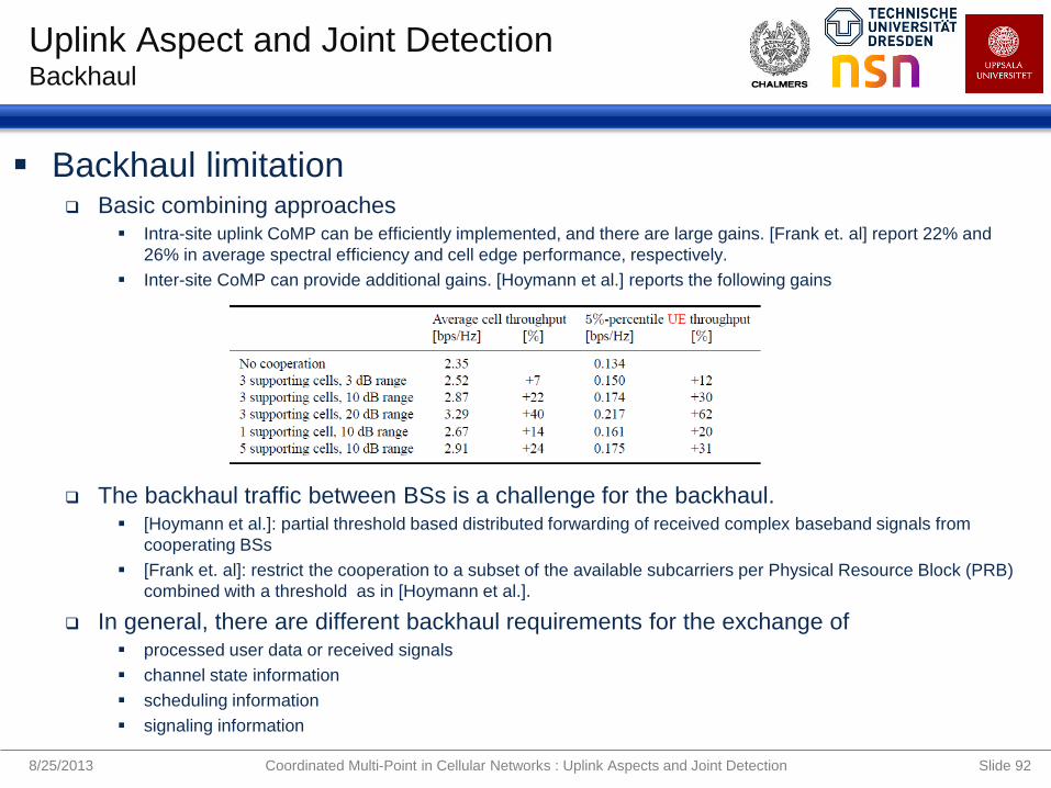
Backhaul limitation Basic combining approaches
Intra-site uplink CoMP can be efficiently implemented, and there are large gains. [Frank et. al] report 22% and
26% in average spectral efficiency and cell edge performance, respectively.
Inter-site CoMP can provide additional gains. [Hoymann et al.] reports the following gains
The backhaul traffic between BSs is a challenge for the backhaul. [Hoymann et al.]: partial threshold based distributed forwarding of received complex baseband signals from
cooperating BSs
[Frank et. al]: restrict the cooperation to a subset of the available subcarriers per Physical Resource Block (PRB)
combined with a threshold as in [Hoymann et al.].
In general, there are different backhaul requirements for the exchange of processed user data or received signals
channel state information
scheduling information
signaling information
8/25/2013 Slide 92 Coordinated Multi-Point in Cellular Networks : Uplink Aspects and Joint Detection

CONCLUSIONS, OUTLOOK
AND FUTURE WORK
8/25/2013 Coordinated Multi-Point in Cellular Networks Slide 93

Conclusions
8/25/2013 Coordinated Multi-Point in Cellular Networks Slide 94
Difference theoretical versus 3GPP results
Rayleigh distr. of channel components: Easily tractable, but unrealistic
LTE overhead in the order of 40 to 50% has to be taken into account
Inter-cluster interference might destroy large parts of the potential gains
ARTIST4G Interference Mitigation Framework
Under ideal conditions (full CSI) close to network wide precoding
Main pillars: cover shifts, partial reporting, interference floor shaping,
2 stage scheduler, …
Directly benefits from improved CSI knowledge and high SNR
What’s next
Analyze optimized channel estimation and prediction solutions going
beyond state of the art model based channel prediction
Generate 3GPP friendly overall system concepts
Reasonable UE processing power
Reasonable feedback overhead, etc.

FIELD TRIAL RESULTS AND
DEMONSTRATION
8/25/2013 Coordinated Multi-Point in Cellular Networks: Field Trial Results and Demonstration Slide 95

Introduction
Theoretical analysis and simulations promise vast increases in spectral
efficiency and currently available technology seems to be ready to support
these ambitious concepts.
Nonetheless, the challenges faced when bringing CoMP to the market have
proven to be manifold. Examples are
required synchronization of all cooperating entities in time and frequency
multi-cell channel estimation
backhaul efficient multi-cell signal processing
Even though significant progress has been made, the often isolated
examination of certain problems is not sufficient to prove the maturity of CoMP
concepts.
System concepts should be evaluated using real channels and hardware.
And system complexity and performance needs to be assessed under real-
world conditions, and thus simulation studies have to be accompanied by field
trials.
Slide 96 Coordinated Multi-Point in Cellular Networks: Field Trial Results and Demonstration

LTE Advanced Testbed
Slide 97 Coordinated Multi-Point in Cellular Networks: Field Trial Results and Demonstration
LTE-Advanced testbed with a total of 5 sites and 13 sectors
• Microwave links between sites
• Focus on physical layer; only minimal MAC layer implemented
• Sites synchronized through GPS and reference normals
• Offline signal processing

LTE Advanced Testbed
CSIRO 08/30/2012 Michael Grieger Slide 98
eNodeB prototyping platform
from Signalion / TU Dresden
Power amplifier and duplexer built by TES
(20W peak, 2520-2540MHz & 2670-2690MHz)
Control computer
Switch
KATHREIN device for electr. downtilt etc.
Switchable power supply
Not visible: • GPS unit for time and frequency sync.
• Frontend for microwave link

LTE Advanced Testbed
8/25/2013 Coordinated Multi-Point in Cellular Networks Slide 99
HBF

LTE Advanced Testbed / Uplink Setup
Slide 100
Uplink Features
• Focus on PHY
• Partial compatibility to LTE Rel. 8
• Offline signal processing
• Quasi-realtime scheduling possible
• Emulated real-time
Control Computer Control Computer
UE UE
eNB eNB eNB
UE
Trans-
mission in
PUSCH
Decode
PDCCH and
UL grant
Output of
CQI info
Sync
Send
PDCCH
DFT
(optional)
Sync
Dump
received
signals
Control Computer
Channel
Estimation
Config
data
Air interface
MATLAB
Signal Processing MATLAB
Signal Processing MATLAB
Signal Processing
GUI
File
Server
Emulated Real-Time
Control
MCSs
Resource Allocation
Power Values
Coordinated Multi-Point in Cellular Networks: Field Trial Results and Demonstration

Signal Processing Architecture
© Google Earth
Channel estimation
• LTE pilot positons
• Code orthogonal pilot positions
Noise covariance estimation • Estimation of noise on empty sub-carriers
Soft demodulation and decoding
• Standard soft demodulation and decoding
• Error vector magnitude SINR estimation
Rate adaptation
• offline evaluation; emulation of optimal rate
adaptation
Slide 101
, ,( )
U K BS Mj
e
Time
sync.
CP-1/
FFT Demap
User #1
User #K
BS #1
BS #M ChEst
EQ
NoiseEst
Det/Dec User
Sym
Coordinated Multi-Point in Cellular Networks: Field Trial Results and Demonstration
a) non coop: decode at different BS b) Joint Decoding (2/3 BSs) c) JD (2/3 BSs) + SIC
References
Slide 104
[3GPP TR 36.819] 3GPP TR 36.819 V11.0.0 (2011-09), 3rd Generation Partnership Project; Technical
Specification Group Radio Access Network; Coordinated multi-point operation for LTE physical
layer aspects (Release 11) .
[Artist4G D1.4] Artist4G Project Deliverable D1.4, Interference Avoidance Techniques and System Design, June
2012. https://ict-artist4g.eu.
[Apelfröjd 2012] Apelfröjd, R ; Sternad, M ; Aronsson, D; “Measurement-based evaluation of robust linear
precoding in downlink CoMP“. IEEE ICC 2012, Ottawa, June 2012.
[Aronsson 2011] Aronsson, D ; Channel Estimation and Prediction for MIMO OFDM Systems: Key design
aspects of Kalman-based algorithms. PhD Thesis, Signals and Systems, Uppsala University,
Mar. 2011.
[Foschini et al.] Foschini, G.J ; Karakayali, K ; Valenzuela, R.A; “Coordinating multiple antenna cellular networks
to achieve enormous spectral efficiency“, IEE Proceedings Communications, 2006.
[Frank et al.] Frank P, M¨uller A and Speidel J 2010 Inter-site joint detection with reduced backhaul capacity
requirements for the 3GPP LTE uplink Proc. IEEE VTC-Fall 2010, pp. 1 –5.
[Gesbert et al. 2011] Gesbert, D ; Kountouris, M ; “Rate scaling laws in multicell networks under distributed power
control and user scheduling”, IEEE Trans. On Information Theory, Jan. 2011.
[Grieger et al. 2011] M. Grieger, P. Marsch and G. Fettweis; Large Scale Field Trial Results on Uplink CoMP with
Multi Antenna Base Stations; in Proceedings of the 74th IEEE Vehicular Technology Conference
(VTC Fall'11), San Francisco, USA, 2011
[Grieger et al. 2012] M. Grieger, V. Kotzsch and G. Fettweis; Comparison of Intra and Inter-Site Coordinated Joint
Detection in a Cellular Field Trial, in Proceedings of the 23rd IEEE International Symposium On
Personal, Indoor And Mobile Radio Communications (PIMRC'12), Sydney, Australia, 2012
[Holma,Toskala] Holma, H ; Toskala, A ; LTE for UMTS: Evolution to LTE-Advanced, 2nd Edition ISBN: 978-0-
470-66000-, 2011
Coordinated Multi-Point in Cellular Networks

References
Slide 105
[Hoymann et al.] Hoymann C, Falconetti L and Gupta R 2009 Distributed uplink signal processing of cooperating
base stations based on IQ sample exchange Proc. IEEE ICC 2009, pp. 1 –5.
[Jafar et al. 2002] Jafar, S.A ; Goldsmith, A.J; “Transmitter optimization for multiple
antenna cellular systems”, IEEE Int. Symp. Information Theory. Lausanne,
Switzerland, vol. 1, 50, 2002.
[Jafar et al. 2004] Jafar, S.A ; Foschini, G.J ; Goldsmith, A.J; “PhantomNet: Exploring
optimal multicellular multiple antenna systems”, EURASIP Journal on
Applied Signal Processing no. 5 pp. 591–604, 2004.
[Lee et al.] Lee, J ; Kim, Y ; Lee, H ; Ng, B.L ; Mazzarese D ; Liu, J ; Xiao, W ; Zhou, Y; „Coordinated
Multipoint Transmission and Reception in LTE-Advanced Systems”. IEEE Communications
Magazine, February 2012, pp. 89-96.
[Li et al.] Li, J ; Papadogiannis, A ; Apelfröjd, R ; Svensson, T ; Sternad, M; ”Performance analysis of
coordinated multipoint transmission schemes with imperfect CSI”. IEEE PIMRC, Sydney,
Australia, Sept. 2012.
[Manioakis] Manioakis, K. ; Jungnickel, V.; ”Synchronization reqirements for OFDM- based cellular
networks with coordinated base stations: Preliminary results”. International OFDM Workshop
(InOWo) 15, 2010, Hamburg, Germany.
[Marsch 2012] Marsch, P ; Fettweis G.P; Coordinated Multi-Point in Mobile Communications. From Theory to
Practice. Cambridge Univ. Press 2011. ISBN 978-1-107-00411-5.
[Mennerich et al.] W. Mennerich, M. Grieger, W. Zirwas and G. Fettweis; Interference Mitigation Framework for
Cellular Mobile Radio Networks, in Hindawi International Journal of Antennas and Propagation
(IJAP), 2013
[Shamai, Zaidel 2001] Shamai, S ; Zaidel, B; “Enhancing the cellular downlink capacity via co-processing at the
transmitting end”. IEEE VTC, Rhodes, Greece, 1745–1749, 2001.
Coordinated Multi-Point in Cellular Networks

References
Slide 106
[Shamai et al. 2002] Shamai, S ; Zaidel, B ; Verdu, S.; “On information theoretic aspects of multi-cell wireless
systems”. Proc. 4th International ITG Conference on Source and Channel Coding. Berlin,
Germany, vol. 4, 2002.
[Schubert and Boche] Schubert, M ; Boche, H. Interference Calculus, A General Framework for Interference
Management and Network Utility Optimization. Springer-Verlag 2012.
[Zirvas et al. 2009] Zirwas, W; Mennerich, W; Schubert, M ; Thiele, L. ; Jungnickel V, and Schulz, E;
"Cooperative transmission schemes," Long Term Evolution: 3GPP LTE radio and cellular
technology, Ed. B. Furht and S.A. Ahson, Auerbach Publications, 2009, pp. 213-263.
[Zirwas, et al. ETT] Zirwas, W ; Mennerich, W, Khan, A ; “Main enablers for advanced interference mitigation”,
Special Issue - LTE-A, ETT Journal, /ett.2567.
[Zirwas et al. 2012] Zirwas, W ; Khan, A. “Channel Estimation for large Cooperation Clusters”, International
OFDM Workshop (InOWo) 17, Essen, Germany, August 2012.
[Willems, Frans 1983] Willems, F.M. ; Frans M.J. ; “The discrete memoryless multiple access channel with partially
cooperating encoders”, IEEE Transactions on Information Theory, Volume: 29, Issue: 3,
Page(s): 441 - 445, May 1983.
[Öhrn et al. 1995] Öhrn, K ; Ahlén, A ; Sternad, M ; “A probabilistic approach to multivariable robust filtering and
open-loop control“. IEEE Transactions on Automatic Control, vol. 40, pp. 405-417, March
1995.
Coordinated Multi-Point in Cellular Networks