Coordinated Control of DFIG System based on Repetitive ...
11
Journal of Power Electronics, Vol. 17, No. 3, pp. 733-743, May 2017 733 https://doi.org/10.6113/JPE.2017.17.3.733 ISSN(Print): 1598-2092 / ISSN(Online): 2093-4718 JPE 17-3-16 Coordinated Control of DFIG System based on Repetitive Control Strategy under Generalized Harmonic Grid Voltages Heng Nian † , Chenwen Cheng * , and Yipeng Song * †,* College of Electrical Engineering, Zhejiang University, Hangzhou, China Abstract This paper develops a coordinated control strategy of the doubly fed induction generator (DFIG) system based on repetitive control (RC) under generalized harmonic grid voltage conditions. The proposed RC strategy in the rotor side converter (RSC) is capable of ensuring smooth DFIG electromagnetic torque that will enable the possible safe functioning of the mechanical components, such as gear box and bearing. Moreover, the proposed RC strategy in the grid side converter (GSC) aims to achieve sinusoidal overall currents of the DFIG system injected into the network to guarantee satisfactory power quality. The dc-link voltage fluctuation under the proposed control target is theoretically analyzed. Influence of limited converter capacity on the controllable area has also been studied. A laboratory test platform has been constructed, and the experimental results validate the availability of the proposed RC strategy for the DFIG system under generalized harmonic grid voltage conditions. Key words: DC-link voltage fluctuation, Doubly fed induction generator system, Generalized harmonic grid voltage, Repetitive control, Sinusoidal output currents, Smooth electromagnetic torque I. INTRODUCTION Doubly fed induction generators (DFIGs) have been widely used in wind power generation systems due to their outstanding merits of variable speed constant frequency operation, adjustable power factor, smaller power ratings of the converter, and so on [1]. Fig. 1 shows the configuration of the DFIG system, where the rotor windings are connected to the rotor side converter (RSC), and the grid side converter (GSC) is used to provide a dc-link voltage for the RSC. In general, the power grid voltages are non-ideal containing harmonic components, which severely deteriorate the output power quality and cause danger to the safe operation of the renewable energy generation system. When the DFIG-based wind-power generation system works under harmonically distorted grid voltage conditions, stator and rotor currents would be seriously distorted; the instantaneous active and reactive power would oscillate; and electromagnetic torque pulsation would occur, which damages the rotor shaft [2]-[8] due to the direct connection of the DFIG’s stator windings to the power grid. By far, several control strategies to improve the operation performance of the DFIG system under harmonic voltage distortions have been investigated [4]-[8]. When the power grid contains 5th and 7th harmonic voltage components [4], [5], the proposed four different control targets for the DFIG system based on the vector control (VC) strategy are achieved, including the sinusoidal stator or rotor currents, smooth active and reactive output power, or smooth electromagnetic torque [6]. The direct power control (DPC) strategy of DFIG under 5th and 7th grid voltage is proposed to achieve the smooth stator active and reactive output power [8]. The resonant closed-loop control of stator currents is presented to achieve the sinusoidal stator currents under 5th and 7th grid voltage distortions. In practice, the grid voltage distortions may contain not only the low-order (5th and 7th), but also high-order harmonics (11th, 13th, 17th, 19th, and so on) components due to the massive usage of power electronic devices and nonlinear loads [9], [17], [18] in rural and weak grids. The traditional resonant regulator of proportional integral resonant (PIR) [4], [5], [7], [8] or vector proportional integral (VPI) is Manuscript received Oct. 24, 2016; accepted Feb. 24, 2017 Recommended for publication by Associate Editor Yong Kang. † Corresponding Author: [email protected] Tel: +86-15088683106, Zhejiang University * College of Electrical Engineering, Zhejiang University, China © 2017 KIPE
Transcript of Coordinated Control of DFIG System based on Repetitive ...

Journal of Power Electronics, Vol. 17, No. 3, pp. 733-743, May 2017 733
https://doi.org/10.6113/JPE.2017.17.3.733
ISSN(Print): 1598-2092 / ISSN(Online): 2093-4718
JPE 17-3-16
Coordinated Control of DFIG System based on Repetitive Control Strategy under Generalized
Harmonic Grid Voltages
Heng Nian†, Chenwen Cheng*, and Yipeng Song*
†,*College of Electrical Engineering, Zhejiang University, Hangzhou, China
Abstract
This paper develops a coordinated control strategy of the doubly fed induction generator (DFIG) system based on repetitive control (RC) under generalized harmonic grid voltage conditions. The proposed RC strategy in the rotor side converter (RSC) is capable of ensuring smooth DFIG electromagnetic torque that will enable the possible safe functioning of the mechanical components, such as gear box and bearing. Moreover, the proposed RC strategy in the grid side converter (GSC) aims to achieve sinusoidal overall currents of the DFIG system injected into the network to guarantee satisfactory power quality. The dc-link voltage fluctuation under the proposed control target is theoretically analyzed. Influence of limited converter capacity on the controllable area has also been studied. A laboratory test platform has been constructed, and the experimental results validate the availability of the proposed RC strategy for the DFIG system under generalized harmonic grid voltage conditions. Key words: DC-link voltage fluctuation, Doubly fed induction generator system, Generalized harmonic grid voltage, Repetitive control, Sinusoidal output currents, Smooth electromagnetic torque
I. INTRODUCTION
Doubly fed induction generators (DFIGs) have been widely used in wind power generation systems due to their outstanding merits of variable speed constant frequency operation, adjustable power factor, smaller power ratings of the converter, and so on [1]. Fig. 1 shows the configuration of the DFIG system, where the rotor windings are connected to the rotor side converter (RSC), and the grid side converter (GSC) is used to provide a dc-link voltage for the RSC.
In general, the power grid voltages are non-ideal containing harmonic components, which severely deteriorate the output power quality and cause danger to the safe operation of the renewable energy generation system. When the DFIG-based wind-power generation system works under harmonically distorted grid voltage conditions, stator and rotor currents would be seriously distorted; the instantaneous active and reactive power would oscillate; and electromagnetic torque pulsation would occur, which
damages the rotor shaft [2]-[8] due to the direct connection of the DFIG’s stator windings to the power grid.
By far, several control strategies to improve the operation performance of the DFIG system under harmonic voltage distortions have been investigated [4]-[8]. When the power grid contains 5th and 7th harmonic voltage components [4], [5], the proposed four different control targets for the DFIG system based on the vector control (VC) strategy are achieved, including the sinusoidal stator or rotor currents, smooth active and reactive output power, or smooth electromagnetic torque [6]. The direct power control (DPC) strategy of DFIG under 5th and 7th grid voltage is proposed to achieve the smooth stator active and reactive output power [8]. The resonant closed-loop control of stator currents is presented to achieve the sinusoidal stator currents under 5th and 7th grid voltage distortions.
In practice, the grid voltage distortions may contain not only the low-order (5th and 7th), but also high-order harmonics (11th, 13th, 17th, 19th, and so on) components due to the massive usage of power electronic devices and nonlinear loads [9], [17], [18] in rural and weak grids. The traditional resonant regulator of proportional integral resonant (PIR) [4], [5], [7], [8] or vector proportional integral (VPI) is
Manuscript received Oct. 24, 2016; accepted Feb. 24, 2017 Recommended for publication by Associate Editor Yong Kang.
†Corresponding Author: [email protected] Tel: +86-15088683106, Zhejiang University
*College of Electrical Engineering, Zhejiang University, China
© 2017 KIPE

734 Journal of Power Electronics, Vol. 17, No. 3, May 2017
Fig. 1. Configuration of DFIG system.
inappropriate to eliminate the detrimental influence on DFIG performance caused by the 6n±1 sequences of grid voltages (5th, 7th, 11th, 13th, 17th, 19th) due to the complex control scheme configuration and strict requirements for DSP’s computation capacity as well as the proper discretization method and delay compensations [10], [17], [18]. The repetitive control (RC) regulator has been reported to have the ability for simultaneous removal of a series of harmonic components having the same fundamental frequency, with the cost of less control complexity and less DSP computation burden compared with the PIR or VPI regulator [11]-[18]. When the RC regulator is employed in the DFIG control, bandwidth based RC regulator, which employs the bandwidth parameter to increase the magnitude response adjacent to the resonant frequencies, was proposed in [17]. Thus, the robustness of the RC regulator against the grid voltage frequency deviation can be improved. In [18], an appropriate magnitude response compensation unit to increase the RC regulator’s magnitude response at high-order harmonic frequency was added. Thus, the control ability for high-order harmonic frequencies was reinforced.
However, only the RSC was investigated for DFIG under generalized harmonic grid voltages in [17] and [18], whereas the GSC control is neglected. Notably, the total active/reactive power or currents of the DFIG system injected into the power grid consist of not only the stator one but also the grid one. GSC would also generate distorted currents and active/reactive power under the generalized harmonic power grid. Thus, the grid conditions are still expected to further deteriorate if no effective control strategy of GSC is applied under generalized harmonic grid voltages. Furthermore, the dc-link voltage would contain harmonic components due to the harmonic voltage conditions, which would cause damage to the dc-link capacitor and deteriorate the control of the capability of RSC and GSC. Thus, it is necessary to develop a coordinated control strategy for DFIG’s RSC and GSC under the generalized harmonic grid voltages and investigate the control effect on the DFIG system.
In order to relieve the mechanical stress on the bearing and gear box and improve the current quality injected into the network from the entire DFIG system, this paper chooses the smooth electromagnetic torque and sinusoidal overall currents (including the stator currents and grid side converter currents) as the control targets for RSC and GSC,
sdqU rdq
U
sdqI rdq
IsR sL rL rR
1 sdqj ψ slip rdqj ψ
mLsdqψ
rdqψ
Fig. 2. DFIG equivalent circuit in synchronous reference frame.
respectively. First, the mathematical models of RSC and GSC under generalized harmonic voltages, the electromagnetic torque, and specifically the current model, are briefly mentioned as a foundation in Section II. Section III describes the proposed strategies in both RSC and GSC, including the design of the RC regulator. Section IV presents the analysis of the dc-link voltage fluctuation under the proposed RC control strategy and the controllable area when the converter capacitor is limited. Finally, Section V establishes the experimental validation of the proposed RC strategy for both RSC and GSC implemented on a 1-kw experimental DFIG system.
II. MATHEMATICAL MODEL OF DFIG SYSTEM UNDER GENERALIZED HARMONIC VOLTAGE
The mathematical model of DFIG’s RSC and GSC under generalized harmonic grid voltages has been established in [5], [17], [18]. Only electromagnetic torque and the current models on the generalized harmonic voltage are presented in this paper.
A. DFIG Electromagnetic Torque
Fig. 2 shows the DFIG equivalent circuit in the synchronous reference frame (SRF). Under the circumstance of generalized harmonic grid voltage conditions, the 6n±1 order harmonic components would exist, and the DFIG stator currents would be correspondingly polluted with the 6n±1 harmonic sequence, which can be written as
1 1(6 1) 6 (6 1) 6(6 1) (6 1)
1
n j n t n j n tsdq sdq sdq n sdq n
ne e
U U U U , (1a)
1 1(6 1) 6 (6 1) 6(6 1) (6 1)
1
n j n t n j n tsdq sdq sdq n sdq n
ne e
I I I I , (1b)
where U is the voltage, I is the current, and ψ is the flux; subscripts d and q represent components on the d and q axes of SRF; superscripts +, (6n-1)- and (6n+1)+ represent SRF, the negative (6n-1) times of fundamental angular frequency reference frame and the positive (6n+1) times of fundamental angular frequency reference frame; subscripts s and r represent components on the stator and rotor sides, respectively; subscripts + (6n-1)- and (6n+1)+ represent the fundamental and harmonic components; Lm is the mutual
inductance between stator and rotor windings, while Ls and
Lr are the stator and rotor leakage inductances; Rs and Rr are
Coordinated Control of DFIG System based on Repetitive Control Strategy under … 735
stator and rotor resistances; ω1 and ωr represent the grid voltage fundamental angular speed and rotor angular speed; ωslip = ω1 – ωr is the slip angular speed; t is time.
As a consequence of harmonic distorted grid voltages and DFIG stator currents, the electromagnetic torque, with the pulsation components of 300, 600, 900 Hz, and so on, can be calculated as [7]
0 61
3 ˆRe[ ]2e p sdq sdq e e n
nT n j T T
ψ I , (2a)
where Te is electromagnetic torque, Te0 and Te6n are the fundamental dc and pulsation components, respectively. The stator flux ψsdq, which is related to the stator voltage, can be presented as
1 1(6 1) 6 (6 1) 6(6 1) (6 1)
1
(6 1) (6 1)(6 1) (6 1)(6 1) (6 1)
(6 1) (6 1)1 1
; ;(6 1) (6 1)
n j n t n j n tsdq sdq sdq n sdq n
n
n nsdq n sdq nn n
sdq n sdq n
e e
j n j n
ψ ψ ψ ψ
U Uψ ψ
. (2b)
Thus, based on (2a) and (2b), the electromagnetic torque pulsation components can be expressed as
1
1
(6 1)(6 1) 6(6 1)
(6 1)
6(6 1)
1 (6 1) 6(6 1)(6 1)
ˆˆ
6 13Re
2 ˆˆ
6 1
nsdq n sdq j n tn
sdq sdq n
pe n
nsdq n sdq j n tn
sdq sdq n
enn
T
en
U IU I
U IU I
. (2c)
From (2), the interaction between grid voltage distortions and stator current distortions would result in the electromagnetic torque pulsation, and the reliable operation of the mechanic components will be jeopardized.
In order to eliminate the electromagnetic torque pulsation, Te6n should be controlled to remain at zero. Appropriate stator current harmonic components (5th, 7th, 11th, 13th, 17th, 19th, and so on) must be produced to allow the first item and second item in bracket of (2c) to counteract each other. Conversely, the control target of smooth DFIG electromagnetic torque is achieved at the cost of the stator current distortions.
B. GSC and DFIG System Overall Currents
The grid voltage applied to GSC is actually the same as that applied to the stator of DFIG, which contains both low and high-order harmonic components apart from the fundamental one. Similar to U+
sdq, the grid voltage applied to GSC in SRF can be presented as
- 6 6(6 -1)- (6 1)(6 -1)- (6 1)
1
( )g gj n j nn ngdq gdq gdq n gdq n
n
e e
U U U U. (3a)
The grid current can be presented as
- 6 6(6 -1)- (6 1)(6 -1)- (6 1)
1
( )g gj n j nn ngdq gdq gdq n gdq n
n
e e
I I I I, (3b)
where subscript g represents components of the grid side, and
g is the phase angle of the fundamental grid voltage vector.
To improve the power quality injected into the power grid, the overall currents of DFIG system, including stator and grid
side converter currents, should be maintained as sinusoidal under generalized harmonic grid voltages.
The DFIG system overall currents can be presented as [4]
1 1
1 1
6 6(6 1) (6 1)(6 1) (6 1)
1
6 6(6 1) (6 1)(6 1) (6 1)
1
alldq sdq gdq
j n t j n tn nsdq sdq n sdq n
n
j n t j n tn ngdq gdq n gdq n
n
e e
e e
I I I
I I I
I I I
, (4)
where subscripts all represent the overall component. From (4), the overall currents contain stator and GSC
currents; thus, GSC currents can be regulated, which have the same magnitude but opposite directions as the stator currents. Then, the stator current distortion can be counteracted by the grid side currents, thereby possibly achieving the control target of sinusoidal overall currents.
III. PROPOSED REPETITIVE CONTROL STRATEGY
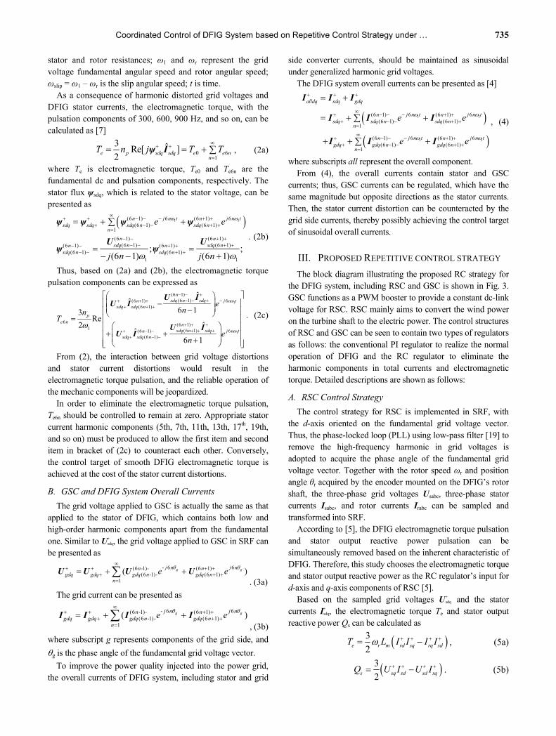
The block diagram illustrating the proposed RC strategy for the DFIG system, including RSC and GSC is shown in Fig. 3. GSC functions as a PWM booster to provide a constant dc-link voltage for RSC. RSC mainly aims to convert the wind power on the turbine shaft to the electric power. The control structures of RSC and GSC can be seen to contain two types of regulators as follows: the conventional PI regulator to realize the normal operation of DFIG and the RC regulator to eliminate the harmonic components in total currents and electromagnetic torque. Detailed descriptions are shown as follows:
A. RSC Control Strategy
The control strategy for RSC is implemented in SRF, with the d-axis oriented on the fundamental grid voltage vector. Thus, the phase-locked loop (PLL) using low-pass filter [19] to remove the high-frequency harmonic in grid voltages is adopted to acquire the phase angle of the fundamental grid voltage vector. Together with the rotor speed ωr and position angle θr acquired by the encoder mounted on the DFIG’s rotor shaft, the three-phase grid voltages Usabc, three-phase stator currents Isabc, and rotor currents Irabc can be sampled and transformed into SRF.
According to [5], the DFIG electromagnetic torque pulsation and stator output reactive power pulsation can be simultaneously removed based on the inherent characteristic of DFIG. Therefore, this study chooses the electromagnetic torque and stator output reactive power as the RC regulator’s input for d-axis and q-axis components of RSC [5].
Based on the sampled grid voltages U+ sdq and the stator
currents I+ sdq, the electromagnetic torque Te and stator output
reactive power Qs can be calculated as
3
2e r m rd sq rq sdT L I I I I , (5a)
3
2s sq sd sd sqQ U I U I . (5b)
736 Journal of Power Electronics, Vol. 17, No. 3, May 2017
rr
sabcU
1
1( )rje
sabcIeT
sQ
*rdq
I
*rdqU
rPIV
rabcIrdqI
rdqI
e sT jQ
sdqI
gabcU
gabcI
1gdqU
gdqI
sdqU
*dcV
*gdI
gdI
*gqjI
gqjI
gdq sdq I I
0
1je
*gdqU
gPIV
1
1
rdqE gdq
E
rRCV
gRCV
Fig. 3. Block diagram of proposed RC strategy for DFIG system.
Then, the two closed-loop controllers for RSC can be illustrated as follows: 1) As a mature control strategy, the PI regulator
implemented in SRF is adopted in this study to regulate the fundamental components of the rotor currents. The rotor current reference I+*
rdq+ can be calculated by the active and reactive power references [7], which are determined by the active power command based on maximum power point track (MPPT) [4] and the grid requirements for reactive power. Since the control strategy was implemented in SRF, the error between I+*
rdq+ and I+
rdq would contain the dc component (corresponding to the fundamental component in the stationary frame) and the 6n order ac components [corresponding to –(6n-1) and +(6n+1) order components in the stationary frame]. Despite the efficiency of the PI regulator in controlling dc components, it cannot regulate ac components due to its low magnitude response at high frequencies. Thus, the PI regulator can only regulate the fundamental component of rotor currents but leave the harmonic components alone.
2) The closed-loop controller containing the RC regulator is employed to suppress the pulsations of electromagnetic torque and stator reactive power. As shown in Fig. 3, the RC regulator’s reference is set to zero to eliminate the 6n order pulsations, and the calculated electromagnetic torque and stator reactive power are considered feedback signals for the d-axis and q-axis, respectively, as (–Te+jQs). As explained in Section II, the two feedback signals would contain both dc and 6n components; thus, error signals between reference 0 and feedback signals (–Te+jQs) would also consist of dc and 6n components. Unfortunately, the dc component would interfere with the normal control capability of the current fundamental component regulation in the PI regulator as illustrated in
Section III.C. Thus, a high-pass filter should be added to the feedback path to filter out the dc component [17], [18].
Finally, the combination of the PI regulator’s output V+ rPI and
the RC regulator’s output V+ rRC as well as the decoupling
compensation E+ rdq [4] as given in (6) contribute to the rotor
controller’s reference voltages U+* rdq as given in (7), which are
used as the input of space vector pulse width modulation (SVPWM) to generate the switching signals.
1
/
rdq r rdq r rdq
m sdq s sdq r sdq s
R j L
L R j L
E I I
U I ψ, (6)
*rdq rPI rRC rdq U V V E , (7)
where Ls = Lm + Ls, Lr = Lm + Lr are the stator and rotor inductances, and σ=1-L2 m/LsLr is the leakage inductance coefficient.
B. GSC Control Strategy
The grid voltage sampling, grid current sampling, and PLL modules in the GSC control strategy are similar to those in the RSC control structure. The dc-link voltage Vdc should also be sampled to remain constant for the supply of RSC. The GSC also has two closed-loop controllers, which can be illustrated as follows:
1) The closed-loop control of dc-link voltage Vdc is implemented based on the PI regulator, and the output is considered as the d-axis current reference I+*
gd+ of the current loop. I+*
gd+ and the q-axis current reference I+* gq+
(which is normally set to 0 to achieve unity power factor operation) would be used as PI regulator inputs of the current control loop to regulate the fundamental components of grid currents.
2) In order to achieve the sinusoidal overall currents of the DFIG system, the reference for the RC regulator in the

Coordinated Control of DFIG System based on Repetitive Control Strategy under … 737
GSC current control loop is set to 0, while the feedback signal is the sum of GSC currents I+
gdq and stator currents I +
sdq . The RC regulator in GSC is also set with the high-pass filter as in RSC control to remove the dc component in the error signal. Then, the harmonic components of GSC currents can be accurately regulated. Thus, the GSC currents would contain the appropriate harmonic components, which have the same magnitude but opposite directions as those in the DFIG stator currents. Thus, the achievement of sinusoidal overall currents can be guaranteed.
The sum of the PI regulator’s output V+ gPI, the RC regulator’s
output V+ gRC, and the decoupling compensation item E+
gdq [4] given in (8) contribute to grid controller’s reference voltages U+* gdq as given in (9), which are used as the input of SVPWM module to generate switching signals.
1gdq g gdq g gdq gdqR j L E I I U , (8)
*gdq gPI gRC gdq U V V E , (9)
where Rg and Lg are grid side line resistance and inductance.
C. RC Regulator
When DFIG works under generalized harmonic voltage conditions, the pulsation components of DFIG electromagnetic torque and stator reactive power would behave as 300, 600, 900 Hz, and so on, while the harmonic sequence of stator currents would also act as 300, 600, 900 Hz, and so on in SRF, thereby requiring the RC regulator to be designed to tune at these corresponding 6n order frequencies.
The transfer function of the RC regulator in discrete domain can be written as
( )( )
1 ( )
N
rcz rc N
Q z zG z k
Q z z
, (10a)
where krc is the gain, Q(z) is commonly chosen as a low-pass filter or a constant smaller than 1, and N is the ratio between the sampling frequency and the fundamental frequency of the harmonic components. In this paper, the sampling frequency is chosen as 10k Hz, while the fundamental frequency of the harmonic components is 300 Hz. Notably, 10000 Hz/300 Hz is non-integral. Consequently, the non-integral N cannot be directly utilized in the discrete RC regulator. [12] introduced an effective linear interpolation method for Q(z) as shown in (10b); thus, Q(z)z-N would approximate z-10000/300.
1( ) (1 )Q z D Dz (10b)
Fig. 4 presents the magnitude and phase responses of the designed RC regulator, with krc = 0.9. From Fig. 4, the magnitude response of the RC regulator at 300, 600, and 900 Hz are 47, 35, and 28 dB, respectively, and this large magnitude response assists in minimizing the ac signal tracking error. Moreover, the phase response of the RC regulator at 300, 600, and 900 Hz are all 0 degree, thereby failing to introduce any phase response shifting and ensuring the accurate ac signal tracking.
Fig. 4. Bode diagram of RC regulator (krc = 0.9, Q(z)= 2/3+1/3*z-1, and N=33)
Furthermore, Fig. 4 shows that the large magnitude response
of 53 dB for the dc control error can be obtained in the RC regulator. Nevertheless, this 53 dB is achieved by the abnormal PI part, which contains the negative proportional part and the positive integral part as –krc/2 + krc/T0s [16]. Notably, the abnormal PI part in the RC regulator would introduce disturbance to the normal working of the current fundamental component regulation in the PI regulator of RSC and GSC. Thus, the first-order high-pass filter is adopted to remove the electromagnetic torque and stator reactive power control error dc component in RSC or current control error dc component in GSC [17, 18]. The cutoff frequency 10Hz is sufficient to remove the dc components,
( )20hp
sG s
s
. (11a)
The discrete form of Ghp(s) can be obtained using the bi-linearization discretization method as
2 2( )
2.006 1.994hp
zG z
z
. (11b)
IV. PERFORMANCE ANALYSIS
A. DC-link Voltage Fluctuation
According to [4], when DFIG works under distorted grid voltage conditions, rotor and grid current distortions would occur under the proposed control targets because the control targets of the sinusoidal currents and smooth electromagnetic torque are contradictory and cannot be achieved simultaneously. The rotor and grid currents with harmonic components would charge and discharge the dc-link capacitor; thus, the DFIG system may suffer from dc-link voltage fluctuation of 300, 600, 900 Hz, and so on. In certain extreme situations, the peak dc-link voltage may exceed the voltage limitation of the dc-link capacitor and threaten the converter’s safety. Thus, investigating the dc-link voltage fluctuation under the control target achievement of smooth electromagnetic torque in RSC and sinusoidal overall current in GSC would be necessary and essential. The dc-link voltage is influenced by

738 Journal of Power Electronics, Vol. 17, No. 3, May 2017
the DFIG electromagnetic power, stator power, and GSC power [4],
dcdc s e g
dVC V P P P
dt , (12)
where Vdc represents the dc-link voltage; C is dc-link capacitor; Pe, Ps, and Pg are the electromagnetic power, DFIG stator power, and GSC power, respectively.
The dc-link voltage in (12), including the dc component, 300, 600, and 900 Hz fluctuation components, can be presented respectively as
0 6 cos 1 6 sin 11
0 6 _ 1 61
cos6 sin 6
sin 6
dc dc dc n dc nn
dc dc n m nn
V V V n V n
V V n
, (13a)
where Vdc0 represents the dc component, Vdc6ncos, Vdc6nsin represent the 6n times cosine and sine fluctuation component, respectively, which can be rewritten according to the trigonometric function as follows:
2 2
6 _ 6 cos 6 sindc n m dc n dc nV V V . (13b)
By substituting (13) into (12), (12) can be rewritten as
0 1 6 _ 1 61
1 6 _ 1 6 6 _ 1 61 1
0 1 6 _ 1 61
6 cos 6
6 cos 6 sin 6
6 cos 6
dcdc
dc dc n m nn
dc n m n dc n m nn n
dc dc n m nn
dVC V
dt
CV n V n
C n V n V n
CV n V n
, (14) where the second item in (14) is comparatively small due to the square multiplication of Vdc6n_m.
Moreover, once the control target is achieved, the electromagnetic torque Pe would contain only the dc component Pe0, and the pulsation components Pe6n is zero.
As mentioned in Section II.A, stator current distortions would occur when the smooth electromagnetic torque is achieved; therefore, the stator active power can be calculated based on the distorted grid voltage and stator current as
1 1
1 1
6 6(6 1) (6 1)(6 1) (6 1)
1
6 6(6 1) (6 1)(6 1) (6 1)
1
3 ˆRe[ ]23
Re2
ˆ ˆ ˆ
U I
U U U
I I I
s sdq sdq
j n t j n tn nsdq sdq n sdq n
n
j n t j n tn nsdq sdq n sdq n
n
P
e e
e e
. (15a) According to (15a), the stator active power pulsation
component can be extracted from (15a) as
1 1
1 1
6 6(6 1) (6 1)6 (6 1) (6 1)
1
6 6(6 1) (6 1)(6 1) (6 1)
1
3 ˆ ˆRe2
ˆ
U I I
I U U
j n t j n tn ns n sdq sdq n sdq n
n
j n t j n tn nsdq sdq n sdq n
n
P e e
e e
.(15b)
From (15b), the stator active power pulsation is mainly caused by the interaction between the grid voltage fundamental component and stator current harmonic components, as well as that between stator current fundamental and grid voltage harmonic components.
Similarly, the GSC active power can be calculated as
1
1
1
1
6(6 1)(6 1)
6(6 1)1(6 1)
6(6 1)(6 1)
6(6 1)1(6 1)
3 ˆRe[ ]2
3Re
2
ˆˆ
ˆ
U I
UU
U
II
I
g gdq gdq
j n tngdq n
gdq j n tnngdq n
j n tngdq n
gdq j n tnngdq n
P
e
e
e
e
. (16a)
The GSC active power pulsation component can be
extracted from (16a) as
1 1
1 1
6 6(6 1) (6 1)6 (6 1) (6 1)
1
6 6(6 1) (6 1)(6 1) (6 1)
1
3 ˆ ˆRe2
ˆ
U I I
I U U
j n t j n tn ng n gdq gdq n gdq n
n
j n t j n tn ngdq gdq n gdq n
n
P e e
e e
.(16b)
Considering that the DFIG stator windings and GSC ac side
are connected together to the power grid via the transformer, the grid voltages U+
gdq+, U(6n-1)- gdq(6n-1)-, U
(6n+1)+ gdq(6n+1)+ in (16b) are the same as
the stator voltages U+ sdq+, U
(6n-1)- sdq(6n-1)-, U
(6n+1)+ sdq(6n+1)+ in (15b). Furthermore,
the proposed control strategy in this paper requires the GSC to compensate the DFIG stator output distorted currents, thereby ensuring the overall sinusoidal currents and (17) can be obtained as
1 1
1 1
6 6(6 1) (6 1)(6 1) (6 1)
1 1
6 6(6 1) (6 1)(6 1) (6 1)
1 1
ˆ ˆ
ˆ ˆ
I I
I I
j n t j n tn ngdq n sdq n
n n
j n t j n tn ngdq n sdq n
n n
e e
e e
. (17)
Accordingly, based on (15b), (16b), and (17), the first item of stator active power pulsation in (15b) and GSC active power pulsation in (16b) would have the same value but opposite sign; thus, these two pulsation components can be accurately cancelled out by each other. Consequently, (12) can be rewritten as
1
1
0 1 6 _ 1 61
0 0 0 6 6
6(6 1)(6 1)
6(6 1)1(6 1)
6 cos 6
3 ˆ ˆRe2
UI I
U
dcdc dc dc n m n
n
s e g s n g n
j n tnsdq n
sdq gdq j n tnnsdq n
dVC V CV n V n
dtP P P P P
e
e
. (18)
From (18), the dc component of electromagnetic power Pe0, stator active power Ps0 and GSC active power Pg0 would be added to zero due to the zero active power absorbed in the dc-link capacitor. Thus, based on (18), the dc-link voltage 6n times fluctuation (when the control target of smooth
Coordinated Control of DFIG System based on Repetitive Control Strategy under … 739
electromagnetic torque and overall sinusoidal current is achieved) can be calculated as
6 _
1 0
3
26
sd gd sq gq
dc n mdc
A I I I IV
n CV
, (19a)
2 2 2 2(6 1) (6 1) (6 1) (6 1)(6 1) (6 1) (6 1) (6 1)n n n n
sd n sq n sd n sq nA U U U U ,
(19b) Theoretically, the maximum dc-link voltage fluctuation
would be the sum of all the dc-link voltage 6n times fluctuation,
_
1 1 0
3
26
sd gd sq gq
dc flucn dc
A I I I IV
n CV
. (20)
According to (19) and (20), the following conclusions can be obtained:
1) The dc-link voltage fluctuation would be relevant to the grid voltage harmonic distortion conditions, which means that heavier grid voltage distortions would cause larger dc-link voltage fluctuations.
2) The dc-link voltage fluctuation would increase in severity when DFIG works under a super-synchronous state (both I+
sdq+ and I+
gdq+ are negative), compared with the situation of DFIG working under a sub-synchronous state (I+
sdq+ is negative, I+ gdq+ is
positive). 3) The larger dc-link capacitor and larger dc-link voltage
value would help suppress the dc-link voltage fluctuation. 4) The grid voltage harmonic component with higher order
sequence (i.e., larger n) would cause comparatively smaller dc-link voltage fluctuations.
When neglecting the converter switching losses, the power flowing through GSC can be calculated as
g sP sP , (21)
where s is the slip rate. To simplify the calculation process, both the DFIG and GSC are assumed to be controlled for operation in unity power factor mode, which means I+
sq+=I+ gq+=0.
Thus, the grid and the stator currents have the following relationship:
gd sdI sI . (22)
Then, (19a) can be simplified as
6 _
1 0
31
26
sd
dc n mdc
AI sV
n CV
. (23)
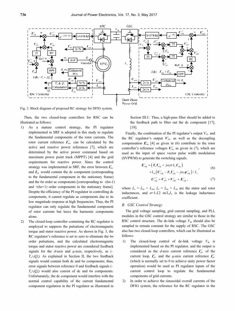
Based on the assumption that r=0.81, the amplitudes of dc-link voltage fluctuations are listed in Table I, with the DFIG parameters listed in Table III and the harmonic stator voltages listed in Table IV.
Table I shows that the amplitudes of the dc-link voltage fluctuations are relatively small compared with the dc-link voltage of 280 V. Thus, the proposed control strategy would not cause large dc-link voltage fluctuations. A larger dc-link
TABLE I AMPLITUDES OF DC-LINK VOLTAGE FLUCTUATIONS USING
DIFFERENT DC-LINK CAPACITORS
DC-link capacitor 6th 12th 18th
330 uF 0.098 V 0.018 V 0.010 V470 uF 0.069 V 0.013 V 0.007 V780 uF 0.041 V 0.008 V 0.004 V
TABLE II PERCENTAGE OF HARMONIC ROTOR VOLTAGES
Harmonic order -5 +7 -11 +13 -17 +19 Stator voltage (%) 1.90 1.87 0.74 0.66 0.62 0.57 Rotor voltage (%) 2.20 1.66 0.79 0.62 0.65 0.55
capacitor would be helpful to suppress the dc-link voltage fluctuations.
B. Impacts of Converter Capacity
The limited converter capacity necessitates the study of the controllable area of the proposed coordinated control strategy. According to [20], the rotor voltages can be calculated as
( )U U ψmrdq s r s
s sr
Lj
L N , (24)
where Nsr is the stator/rotor turn ratio. When (2b) is substituted into (24), the harmonic rotor voltages can be written as
(6 1)(6 1)(6 1)
(6 1)1
[1 ](6 1)
UU
nm sdq nn r
rdq ns sr
L
L N n
, (25a)
(6 1)(6 1)(6 1)
(6 1)1
[1 ](6 1)
UU
nm sdq nn r
rdq ns sr
L
L N n
. (25b)
From (25), the negative (6n-1) order harmonic rotor voltages
decrease as n increases and increase as r increases; the positive (6n+1) order harmonic rotor voltages increase as n
increases and decrease as r increases. Given that (6n+1)1
and (6n-1)1 are generally much larger than r, (25) can be simplified as
(6 1)(6 1)(6 1)
(6 1)
UU
nm sdq nn
rdq ns sr
L
L N
, (26a)
(6 1)(6 1)(6 1)
(6 1)
UU
nm sdq nn
rdq ns sr
L
L N
. (26b)
Based on the assumption that r=0.81, the percentages of harmonic rotor voltages to the fundamental rotor voltage are shown in Table II, with the DFIG parameters listed in Table III and the harmonic stator voltages listed in Table IV.
In general, the low-order harmonic stator voltages have higher amplitudes that would produce higher harmonic components in the rotor voltages. The rotor voltage may exceed the maximum voltage that the dc-link voltage can provide. Then, the control targets in the proposed control strategy cannot be fully achieved.
As discussed, the amplitudes of harmonic components in both GSC and stator currents are the same, whereas the

740 Journal of Power Electronics, Vol. 17, No. 3, May 2017
Fig. 5. Schematic of the experiment system
directions are opposite, which would also increase the amplitudes of grid currents. Thus, the current ratings of the generator and converter are also the limiting factors for the application of the proposed control strategy. In practice, the harmonic components in grid voltages are relatively small, and the proposed coordinated control strategy of the DFIG system can work effectively.
V. EXPERIMENTAL VALIDATION
A. Experiment Setup
Fig. 5 shows the schematic of the experimental 1 kW DFIG rig, where a squirrel cage induction motor is used to simulate the wind turbine driving the DFIG rotor. The Chroma 61704 functions as the power grid, which can generate the required generalized harmonic voltages. Only the 5th, 7th, 11th, 13th, 17th, and 19th order harmonic components are considered in the grid voltage for convenience in the experiment, which are initially set as 1.92%, 1.87%, 0.76%, 0.72%, 0.62%, and 0.59%, respectively. The DFIG stator output active power is 800 W, and the reactive power is 0 Var to realize the unit power factor operation. With the synchronous speed of 1000 rpm, the DFIG operates in a sub-synchronous state whose rotor speed is 800 rpm. The dc-link voltage controlled by GSC is set to 280 V. The RSC and GSC control strategies are implemented on two separate DSPs of TMS320F28335, with the sampling frequency and IGBT-switching frequency both at 10 kHz. A Yokogawa DL750 oscilloscope is used to acquire the experimental waveforms. Detailed parameters of the experimental DFIG system are listed in Table III.
B. Experiment Results
For comparison, Fig. 6 presents the experimental results of DFIG under harmonically distorted grid voltage conditions, with the conventional VC strategy containing the PI regulators only. The distorted grid voltage with harmonic components would result in harmonic components of the same frequencies
TABLE III
PARAMETERS OF EXPERIMENTAL DFIG SYSTEM
Rated power 1 kW Stator/rotor turns ratio 0.33
Grid voltage (RMS of phase to phase)
110 V DFIG stator leakage
inductance Lσs 3.0 mH
DFIG mutual inductance Lm
90.1 mH
DFIG rotor leakage inductance Lσr
3.0 mH
GSC line inductance Lg 14 mH DFIG pole pairs 3
Stator resistance Rs 1.01 Rotor resistance Rr 0.88
DC-link capacitor Cdc 780 uF DC-link voltage Vdc 280 V
Sample frequency 10k Hz Switching frequency 10 kHz
Fig. 6. Experimental result of DFIG under harmonically distorted grid voltage condition when RC control is disabled. [① Usabc stator line voltage (250 V/div), ② Itabc total current (7.5 A/div), ③ Isabc stator line current (10 A/div), ④ Igabc grid line current (4 A/div), ⑤ Ps stator active power (600 W/div), ⑥ Qs stator reactive power (600 var/div), ⑦ Te electromagnetic torque (7 Nm/div), ⑧ Vdc dc-link voltage (10 V/div)].
in both the stator and the grid currents. Thus, the total currents would consist of harmonic components of 8.22% 5th, 6.56% 7th, 2.70% 11th, 1.66% 13th, 1.42% 17th, and 1.34% 19th sequence, as listed in Table IV. Then, the pulsations of stator output reactive power and electromagnetic torque would inevitably be produced, that is, ±24.28 Var and ±0.225 Nm of 6th, ±2.46 Var and ±0.052 Nm of 12th, ±1.23 Var and ±0.012 Nm of 18th sequence. If no effective control method is adopted to eliminate these harmonic components, the safe operation of DFIG is threatened, and deterioration of electric power injected into the network would be expected. According to (19a), larger dc-link voltage and capacitor would help suppress the dc-link voltage fluctuation. This experiment sets the dc-link voltage Vdc to 280 V and chooses the dc-link capacitor as the film capacitor of 780 uF with small equivalent series inductance and resistance, which is adequately large to suppress the high-frequency fluctuation of the dc-link voltage as shown in Fig. 6.
Fig. 7 shows the experimental results of DFIG under generalized harmonic grid voltages when the RC regulator for

Coordinated Control of DFIG System based on Repetitive Control Strategy under … 741
Fig. 7. Experimental result of DFIG under harmonically distorted grid voltage condition when the RC control of RSC is enabled, and RC control of GSC is disabled. [①Usabc stator line voltage (250 V/div), ②Itabc total current (7.5 A/div), ③Isabc stator line current (10 A/div), ④Igabc grid line current (4 A/div), ⑤Ps stator active power (600 W/div), ⑥Qs stator reactive power (600 var/div), ⑦Te electromagnetic torque (7 Nm/div), ⑧Vdc dc-link voltage(10 V/div)].
RSC is enabled, whereas the RC regulator for GSC is disabled. From Fig. 7, the pulsations of both reactive power and the electromagnetic torque are suppressed effectively. Table V provides a quantitative description to validate the effectiveness of the proposed control strategy. The harmonic components of reactive power and electromagnetic torque are ±6.78 Var and ±0.100 Nm for 6th, ±1.73 Var and ±0.019 Nm for 12th, ±0.86 Var and ±0.003 Nm for 18th sequences, respectively. Moreover, the performance is effectively improved compared with the results when no RC is enabled for RSC.
When RC regulators (not only for the RSC but also the GSC) are enabled, the total currents (sum of stator and GSC currents) harmonic components would also be reduced, apart from the excellent reactive power and electromagnetic torque behavior, as shown in Fig. 8. The total current harmonic components would be restrained to 0.72% for 5th, 0.51% for 7th, 0.91% for 11th, 0.84% for 13th, 1.01% for 17th, and 0.99% for 19th sequence, which are listed in Table IV.
Thus, the proposed control method with both RC regulators for RSC and GSC can effectively improve the DFIG performance with less harmonic components in total currents and less pulsation of the reactive power and the electromagnetic torque.
Fig. 9 shows the experimental results of DFIG output active power stepping from 400 W to 800 W under harmonically distorted grid voltage condition when both RC regulators for RSC and GSC are enabled. When the active power increases from 400 W to 800 W, the currents including stator currents, grid currents, total currents, and electromagnetic torque also double while the reactive power remains zero. The PI closed-loop controlling the rotor currents work effectively
Fig. 8. Experimental result of DFIG under harmonically distorted grid voltage condition when RC control of both RSC and GSC is enabled. [①Usabc stator line voltage (250 V/div), ②Itabc total current (7.5 A/div), ③Isabc stator line current (10 A/div), ④Igabc grid line current (4 A/div), ⑤Ps stator active power (600 W/div), ⑥Qs stator reactive power (600 var/div), ⑦Te electromagnetic torque (7 Nm/div), ⑧Vdc dc-link voltage (10 V/div)].
TABLE IV EXPERIMENT RESULTS OF TOTAL CURRENT
Grid voltage
Total current when no RC is enabled
Total current when RC for GSC is enabled
5th 1.90% 8.22% 0.72% 7th 1.87% 6.56% 0.51%
11th 0.74% 2.70% 0.91%
13th 0.66% 1.66% 0.84%
17th 0.62% 1.42% 1.01%
19th 0.57% 1.34% 0.99%
TABLE V EXPERIMENT RESULT OF ELECTROMAGNETIC TORQUE
Reactive power/var Electromagnetic torque/Nm
RC for RSC
is disabled
RC for RSC
is enabled
RC for RSC is
disabled
RC for RSC is
enabled
6th ±24.28 ±6.78 ±0.225 ±0.100 12th ±2.46 ±1.73 ±0.052 ±0.019
18th ±1.23 ±0.86 ±0.012 ±0.003
during the transient process of the stator active power stepping period, which is less than 50 ms. The RC regulators are adopted to achieve sinusoidal total current, smooth reactive power, and electromagnetic torque.
Fig. 10 shows the experimental results of DFIG when DFIG rotor speed accelerating from 800 rpm (0.8 pu) to 1200 rpm (1.2 pu). The active and reactive powers are maintained at 800 W and 0 Var. Apparently, the total currents injected into the grid are sinusoidal, while the active and reactive power also remain constant during the acceleration period. When the rotor speed changes from 800 rpm to 1200 rpm, the direction of active power flowing in the GSC would reverse, and GSC would generate power into the grid. Consequently, the currents

742 Journal of Power Electronics, Vol. 17, No. 3, May 2017
Fig. 9. Experimental result of DFIG with stator output active power stepping from 400 W to 800 W under harmonically distorted grid voltage condition when RC control is enabled.
Usa
bc(2
50V
/div
)
I tab
c(7
.5A
/div
)
I sab
c(1
0A/d
iv)
Ps
(600
W/d
iv)
Qs
(600
var/
div)
Speed
I gab
c(4
A/d
iv)
(a) Full view.
(b) Enlarged view.
Fig. 10. Experimental result of DFIG when DFIG operates from a sub-synchronous state (0.8 pu) to a super-synchronous state (1.2 pu) with RC control enabled. (a) Full view (200 ms/div) and (b) Enlarged view (20 ms/div). in the GSC would initially decrease and increase when the speed exceeds the synchronous speed (1000 rpm). The sum of the stator and GSC currents also increases because the total active power injected into the grid grows during the entire acceleration period. Notably, the stator active power remains constant (800 W) regardless of the rotor speed, thereby
maintaining the unchanged stator currents while the speed varies. Inevitably, power losses (e.g., rotor copper loss) and converter loss occur in the experiment system. Although the rotor power is constant when the rotor speeds are at 800 rpm and 1200 rpm, the direction of the rotor current changes because the slip ratio changes from 0.2 to –0.2. Thus, the grid power at 1200 rpm becomes less than that at 800 rpm, which can be observed from the change in the grid current amplitude at different speeds. The experimental result verifies that the proposed control strategy is applicable in the practical wind power track.
VI. CONCLUSIONS
This paper proposes a coordinated control strategy of the DFIG system, including both RSC and GSC under generalized harmonic grid voltage condition. RC regulators are adopted in RSC to eliminate pulsations in electromagnetic torque and reactive power and in GSC to acquire the sinusoidal total currents injected into the grid. Not only low-order (5th and 7th) but also high-order (11th, 13th, 17th, 19th, and so on) components can be suppressed due to the high-magnitude response of the RC regulator at the point of harmonic frequencies. The DC-link voltage fluctuation under the proposed control target is theoretically analyzed, which implies that the larger dc-link capacitor and higher dc-link voltage would help suppress the dc-link voltage fluctuations. Finally, experimental results are given to validate the effectiveness of the proposed coordinated control strategy of the DFIG system.
REFERENCES
[1] R. Pena, J. C. Clare, and G. M. Asher, “Doubly fed induction generator using back-to-back PWM converters and its application to variable-speed wind-energy generation,” IEE Proc.-Elect. Power Appl., Vol. 143, No. 3, pp. 231-241, May 1996.
[2] National Grid Transco, Appendix 1, Extracts from the Grid Code— Connection Conditions, Feb. 2004. [Online]. Available: http://www. nationalgrid.com.
[3] IEEE Recommended Practices and Requirements for Harmonic Control in Electrical Power Systems, IEEE Standard 519–1992, 1993.
[4] J. Hu, H. Xu, and Y. He, “Coordinated control of DFIG’s RSC and GSC under generalized unbalanced and distorted grid voltage conditions,” IEEE Trans. Ind. Electron., Vol. 60, No. 7, pp. 2808-2819, Jul. 2013.
[5] J. Hu, H. Nian, H. Xu, and Y. He, “Dynamic modeling and improved control of DFIG under distorted grid voltage conditions,” IEEE Trans. Energy Convers., Vol. 26, No. 1, pp. 163-175, Mar. 2011.
[6] H. Nian and Y. Song, “Direct power control of doubly fed induction generator under distorted grid voltage,” IEEE Trans. Power Electron., Vol. 29, No. 2, pp. 894-905, Feb. 2014.
[7] C. Liu, F. Blaabjerg, W. Chen, and D. Xu, “Stator current harmonic control with resonant controller for doubly fed induction generator,” IEEE Trans. Power Electron., Vol. 27, No. 7, pp. 3207-3220, Jul. 2012.

Coordinated Control of DFIG System based on Repetitive Control Strategy under … 743
[8] J. B. Hu and Y. K. He, “Modeling and enhanced control of DFIG under unbalanced grid voltage conditions,” Electric Power Systems Research, Vol. 79, No. 2, pp.273-281, Feb. 2009.
[9] X. Wang, F. Blaabjerg, and Z. Chen, “Autonomous control of inverter‐interfaced distributed generation units for harmonic current filtering and resonance damping in an islanded microgrid,” IEEE Trans. Ind. Appl., Vol. 50, No. 1, pp. 452-461, Jan.-Feb. 2014.
[10] A. G. Yepes, F. D. Freijedo, J. Doval-Gandoy, O. López, J. Malvar, and P. Fernandez-Comesaña, “Effects of discretization methods on the performance of resonant controllers”, IEEE Trans. Power Electron., Vol. 25, No. 7, 1692-1712, Jul., 2010.
[11] F. Wei, X. Zhang, D. M. Vilathgamuwa, S. S. Choi, and S. Wang, “Mitigation of distorted and unbalanced stator voltage of stand-alone doubly fed induction generators using repetitive control technique,” IET Electr. Power Appl., Vol. 7, No. 8, pp. 654-663, 2013.
[12] D. Chen, J. Zhang, and Z. Qian, “Research on fast transient and 6n± 1 harmonics suppressing repetitive control scheme for three-phase grid-connected inverters,” IET Power Electron., Vol. 6, No. 3, pp. 601-610, 2013.
[13] E. Kurniawan, Z.W. Cao, and Z. H. Man, “Design of robust repetitive control with time-varying sampling periods,” IEEE Trans. Ind. Electron., Vol. 61, No. 6, pp. 2834-2841, Jun., 2014.
[14] W. Z. Lu, K. L. Zhou, D. W. Wang, and M. Cheng, “A generic digital nk±m order harmonic repetitive control scheme for PWM converters,” IEEE Trans. Ind. Electron., Vol. 61, No. 3, pp. 1516–1527, Mar. 2014.
[15] B. Zhang, K. L. Zhou, and D. W. Wang, “Multirate repetitive control for PWM DC/AC converters,” IEEE Trans. Ind. Electron., Vol. 61, No. 6, pp.2883-2890, Jun., 2014.
[16] Y. Yang, K. Zhou, M. Cheng, and B. Zhang, “Phase compensation multiresonant control of CVCF PWM converters,” IEEE Trans. Power Electron., Vol. 28, No. 8, pp. 3923-3930, Aug. 2013.
[17] Y. Song and H. Nian, “Sinusoidal output current implementation of DFIG using repetitive control under generalized harmonic power grid with frequency deviation,” IEEE Trans. Power Electron., Vol. 30, No. 12, pp. 6751-6762, Dec. 2015.
[18] Y. Song and H. Nian. “Enhanced grid-connected operation of DFIG using improved repetitive control under generalized harmonic power grid,” IEEE Trans. Energy Convers., Vol. 30, No. 3, pp. 1019-1029, Sep. 2015.
[19] S. Golestan, M. Monfared, F. D. Freijedo. “Design-oriented study of advanced synchronous reference frame phase-locked loops,” IEEE Trans. Power Electron., Vol. 28, No. 2, pp. 765-778, Feb. 2013.
[20] J. B. Hum and Y. He, “DFIG wind generation systems operating with limited converter rating considered under unbalanced network conditions – analysis and control design,” Renew. Energy, Vol 36, No. 2, pp. 829-847, 2011.
Heng Nian (M’09,SM’14) obtained his B.Eng. and M.Eng. degrees from HeFei University of Technology, China. He later gained his Ph.D. degree from Zhejiang University, China in 1999, 2002, and 2005, respectively, all in the field of electrical engineering. From 2005 to 2007, he served as a postdoctoral faculty member at the
College of Electrical Engineering, Zhejiang University, China. In 2007, he was promoted as an associate professor. Since 2016, he has been a full professor at the College of Electrical Engineering, Zhejiang University. His current research interests include the optimal design and operation control of windpower generation systems.
Chenwen Cheng was born in Xuzhou, China. He gained his B.Sc. degree from the College of Electrical Engineering, Zhejiang University, Hangzhou, China, in 2012. He is currently working toward obtaining a Ph.D degree at the same university. His research interests include motor control and windpower generation systems.
Yipeng Song (M’16) was born in Hangzhou, China. He obtained his B.Sc. and Ph.D. degrees from the College of Electrical Engineering, Zhejiang University, Hangzhou, China, in 2010 and 2015, respectively. He is currently working as a postdoctoral researcher at the Department of Energy Technology in Aalborg University, Denmark.
His current research interests are motor control with power electronic devices in renewable-energy conversion, particularly the control and operation of doubly fed induction generators for wind power generation.